EP3597114A1 - Verschlussvorrichtung und freisetzungssystem - Google Patents
Verschlussvorrichtung und freisetzungssystem Download PDFInfo
- Publication number
- EP3597114A1 EP3597114A1 EP19194806.6A EP19194806A EP3597114A1 EP 3597114 A1 EP3597114 A1 EP 3597114A1 EP 19194806 A EP19194806 A EP 19194806A EP 3597114 A1 EP3597114 A1 EP 3597114A1
- Authority
- EP
- European Patent Office
- Prior art keywords
- wire
- sealing device
- defect
- wires
- proximal
- Prior art date
- Legal status (The legal status is an assumption and is not a legal conclusion. Google has not performed a legal analysis and makes no representation as to the accuracy of the status listed.)
- Pending
Links
Images


Classifications
-
- A—HUMAN NECESSITIES
- A61—MEDICAL OR VETERINARY SCIENCE; HYGIENE
- A61B—DIAGNOSIS; SURGERY; IDENTIFICATION
- A61B17/00—Surgical instruments, devices or methods, e.g. tourniquets
- A61B17/0057—Implements for plugging an opening in the wall of a hollow or tubular organ, e.g. for sealing a vessel puncture or closing a cardiac septal defect
-
- A—HUMAN NECESSITIES
- A61—MEDICAL OR VETERINARY SCIENCE; HYGIENE
- A61B—DIAGNOSIS; SURGERY; IDENTIFICATION
- A61B17/00—Surgical instruments, devices or methods, e.g. tourniquets
- A61B17/00234—Surgical instruments, devices or methods, e.g. tourniquets for minimally invasive surgery
- A61B2017/00238—Type of minimally invasive operation
- A61B2017/00243—Type of minimally invasive operation cardiac
-
- A—HUMAN NECESSITIES
- A61—MEDICAL OR VETERINARY SCIENCE; HYGIENE
- A61B—DIAGNOSIS; SURGERY; IDENTIFICATION
- A61B17/00—Surgical instruments, devices or methods, e.g. tourniquets
- A61B2017/00526—Methods of manufacturing
-
- A—HUMAN NECESSITIES
- A61—MEDICAL OR VETERINARY SCIENCE; HYGIENE
- A61B—DIAGNOSIS; SURGERY; IDENTIFICATION
- A61B17/00—Surgical instruments, devices or methods, e.g. tourniquets
- A61B17/0057—Implements for plugging an opening in the wall of a hollow or tubular organ, e.g. for sealing a vessel puncture or closing a cardiac septal defect
- A61B2017/00575—Implements for plugging an opening in the wall of a hollow or tubular organ, e.g. for sealing a vessel puncture or closing a cardiac septal defect for closure at remote site, e.g. closing atrial septum defects
- A61B2017/00579—Barbed implements
-
- A—HUMAN NECESSITIES
- A61—MEDICAL OR VETERINARY SCIENCE; HYGIENE
- A61B—DIAGNOSIS; SURGERY; IDENTIFICATION
- A61B17/00—Surgical instruments, devices or methods, e.g. tourniquets
- A61B17/0057—Implements for plugging an opening in the wall of a hollow or tubular organ, e.g. for sealing a vessel puncture or closing a cardiac septal defect
- A61B2017/00575—Implements for plugging an opening in the wall of a hollow or tubular organ, e.g. for sealing a vessel puncture or closing a cardiac septal defect for closure at remote site, e.g. closing atrial septum defects
- A61B2017/00592—Elastic or resilient implements
-
- A—HUMAN NECESSITIES
- A61—MEDICAL OR VETERINARY SCIENCE; HYGIENE
- A61B—DIAGNOSIS; SURGERY; IDENTIFICATION
- A61B17/00—Surgical instruments, devices or methods, e.g. tourniquets
- A61B17/0057—Implements for plugging an opening in the wall of a hollow or tubular organ, e.g. for sealing a vessel puncture or closing a cardiac septal defect
- A61B2017/00575—Implements for plugging an opening in the wall of a hollow or tubular organ, e.g. for sealing a vessel puncture or closing a cardiac septal defect for closure at remote site, e.g. closing atrial septum defects
- A61B2017/00597—Implements comprising a membrane
-
- A—HUMAN NECESSITIES
- A61—MEDICAL OR VETERINARY SCIENCE; HYGIENE
- A61B—DIAGNOSIS; SURGERY; IDENTIFICATION
- A61B17/00—Surgical instruments, devices or methods, e.g. tourniquets
- A61B17/0057—Implements for plugging an opening in the wall of a hollow or tubular organ, e.g. for sealing a vessel puncture or closing a cardiac septal defect
- A61B2017/00575—Implements for plugging an opening in the wall of a hollow or tubular organ, e.g. for sealing a vessel puncture or closing a cardiac septal defect for closure at remote site, e.g. closing atrial septum defects
- A61B2017/00606—Implements H-shaped in cross-section, i.e. with occluders on both sides of the opening
-
- A—HUMAN NECESSITIES
- A61—MEDICAL OR VETERINARY SCIENCE; HYGIENE
- A61B—DIAGNOSIS; SURGERY; IDENTIFICATION
- A61B17/00—Surgical instruments, devices or methods, e.g. tourniquets
- A61B17/0057—Implements for plugging an opening in the wall of a hollow or tubular organ, e.g. for sealing a vessel puncture or closing a cardiac septal defect
- A61B2017/00575—Implements for plugging an opening in the wall of a hollow or tubular organ, e.g. for sealing a vessel puncture or closing a cardiac septal defect for closure at remote site, e.g. closing atrial septum defects
- A61B2017/00623—Introducing or retrieving devices therefor
Definitions
- This disclosure relates to sealing devices for repair of a cardiac or vascular defect or tissue opening, and to delivery systems for delivering and deploying the sealing devices.
- Occluding device implantation by open-heart surgery has historically been used to treat cardiac defects or tissue openings. More recently, to avoid the trauma and complications associated with open-heart surgery, a variety of trans-catheter closure techniques have been developed. In such techniques, an occluding device is delivered through a catheter to the site of the opening or defect, where it is deployed.
- trans-catheter-delivered devices are known, including devices that require assembly at the site of the tissue opening or require threading or "buttoning" of discrete device elements.
- Other devices include self-expanding devices.
- An example of a self-expanding device includes an occlusion bag, a tube, a guide catheter, a super elastic wire, a release mechanism, and a delivery sheath.
- the super elastic wire is attached to the release mechanism and the wire, and the release mechanism, occlusion bag, guide catheter and tube are inserted into the delivery sheath for transport to an aperture. After delivery, the occlusion bag is placed within the aperture and the wire is deployed within the bag.
- the bag and wire are repositioned, if necessary, and the release mechanism is activated to release the wire.
- a self-expanding device includes a shape-set tubular metal fabric device and, optionally, an occluding fiber included in the hollow portions of the device.
- the metal fabric defines a medical device shaped like a bell, which can be collapsed for passage through a catheter for deployment in a channel of a patient's body.
- trans-catheter delivery devices are deployed using one of two basic techniques: pulling back an outer catheter to release the device, or pushing the device free of the catheter with a push rod.
- Each of these systems utilizes a handle to actuate the mechanism used to deploy the device.
- An example of such a system includes a flexible urging member for urging the sealing device through the catheter and a remotely located control means for advancing the urging member.
- the control means includes a threaded, tubular shaft connected to the urging member and a manually rotatable threaded rotor mounted on the shaft. The threads on the rotor mate with the threads on the shaft so that the rotation of the rotor through a known angle will advance the shaft and the urging member a known distance.
- An example of a system that utilizes a pull back outer shaft or catheter includes a handle that may selectively hold the delivery system components at any configuration during deployment and positioning of the device.
- the outer catheter of such a system is pulled back to release the device by actuating a sliding lever and a rotating finger ring on the delivery system handle.
- a medical device for sealing a defect or structure in a heart includes a wire frame with a plurality of wires that each extend from a proximal end of the wire frame to a distal end of the wire frame, and a sealing member in contact with the wire frame.
- the wires form a first wire aggregation element near the proximal end of the wire frame and a second wire aggregation element near the distal end of the wire frame.
- the first wire aggregation element is formed from first end portions of each wire of the plurality of wires
- the second wire aggregation element is formed from second end portions of each wire of the plurality of wires.
- the wires also form a first occluding member that includes, for each wire of the plurality of wires, a first generally linear segment and a first generally curved segment that together define a petal of the first occluding member.
- the first occluding member is disposed adjacent the first wire aggregation element.
- the wires also form a second occluding member that includes, for each wire of the plurality of wires, a second generally linear segment and a second generally curved segment that together define a petal of the second occluding member.
- the second occluding member is disposed adjacent the second wire aggregation element.
- the wires also form a defect-occupying portion disposed between the first occluding member and the second occluding member.
- Each wire of the plurality of wires includes, in the defect-occupying portion, a third generally linear segment, a fourth generally linear segment, and a third curved segment disposed between the third generally linear segment and the fourth generally linear segment.
- the sealing member includes one or more openings providing fluid passageways. The sealing member is in contact with the wire frame such that the one or more openings are disposed on at least one of the first occluding member and the second occluding member.
- a medical device for sealing a defect or structure in a heart includes a wire frame that includes a plurality of wires that each extend from a proximal end of the wire frame to a distal end of the wire frame, and a sealing member configured to define one or more fluid passage openings through the sealing member.
- the wires form a first wire aggregation element near the proximal end of the wire frame and a second wire aggregation element near the distal end of the wire frame.
- the first wire aggregation element is formed from first end portions of each wire of the plurality of wires
- the second wire aggregation element is formed from second end portions of each wire of the plurality of wires.
- the wires also form a first occluding member disposed adjacent the first wire aggregation element.
- the wires also form a second occluding member disposed adjacent the second wire aggregation element.
- the wires also form a defect-occupying portion disposed between the first occluding member and the second occluding member.
- Each wire of the plurality of wires includes, in the defect-occupying portion, a first generally linear segment, a second generally linear segment, and a curved segment disposed between the first generally linear segment and the second generally linear segment.
- the sealing member is disposed on the frame such that the one or more fluid passage openings are located on one or both of the first occluding member and the second occluding member.
- an implantable medical device for sealing an aperture in tissue includes a frame, a sealing member in contact with the frame, and an attachment feature adapted to couple with one or more components of a delivery system.
- the frame includes: a) a first occluding member that is adapted to conform to a geometry of a first tissue surface and to provide an apposition force against the first tissue surface, b) a second occluding member that is adapted to conform to a geometry of a second tissue surface and to provide an apposition force against the second tissue surface, and c) a defect-occupying member disposed between the first occluding member and the second occluding member.
- the frame is defined by a plurality of elongate members, each of which includes: a first portion that defines a petal of the first occluding member; a second portion that defines a petal of the second occluding member; and a third portion, disposed between the first portion and the second portion.
- the third portion includes a first generally linear segment, a second generally linear segment, and a curved segment disposed between the first generally linear segment and the second generally linear segment.
- the sealing member is discontinuous in at least one location on the sealing member such that one or more fluid passages through one or more petals of the first occluding member or the second occluding member are defined.
- an implantable medical device for sealing a defect that extends between a first tissue surface and a second tissue surface includes a frame, a sealing member that substantially covers the frame, and an attachment member adapted to couple with one or more components of a delivery system.
- the frame includes a first occluding member, a second occluding member, and a defect-occupying member between the first occluding member and the second occluding member.
- the frame is defined by a plurality of elongate members, and each elongate member of the plurality of elongate members includes: a first portion that defines a petal of the first occluding member; a second portion that defines a petal of the second occluding member; and a third portion, disposed between the first portion and the second portion.
- the third portion defines an inflection region of the defect-occupying member.
- the sealing member is configured with one or more separations that define an open area in the sealing member on the first occluding member or the second occluding member.
- a sealing device in another implementation, includes an expandable frame comprising a plurality of wires and a sealing member that at least partially encapsulates the expandable wire frame.
- Each of the wires extend from a proximal end to a distal end of the frame.
- First and second portions of each of the plurality of wires form a wound proximal eyelet and a wound distal eyelet.
- the plurality of wires form a proximal disk and a distal disk when the sealing device assumes a deployed configuration.
- the proximal disk and the distal disk are each disposed between the proximal eyelet and the distal eyelet.
- Each wire of the plurality of wires forms a respective petal of the proximal disk and forms a respective petal of the distal disk.
- Adjacent petals of the proximal disk overlap one another and are not interwoven with one another.
- Adjacent petals of the distal disk overlap one another and are not interwoven with one another.
- Each of the petals is configured to conform to tissue.
- the sealing member is configured with one or more openings defining passages through the sealing member located on at least one petal of the proximal disk or the distal disk.
- a sealing device in another implementation, includes an expandable frame comprising a plurality of wires and a sealing member in contact with the frame.
- Each of the wires extend from a proximal end to a distal end of the frame.
- First and second portions of each of the plurality of wires form a wound proximal eyelet and a wound distal eyelet.
- the plurality of wires form a proximal disk and a distal disk when the sealing device assumes a deployed configuration.
- the proximal disk and the distal disk are each disposed between the proximal eyelet and the distal eyelet.
- Each wire of the plurality of wires forms a respective petal of the proximal disk and forms a respective petal of the distal disk.
- the sealing member is configured with one or more discontinuities where a fluid passage through the sealing member is defined.
- a sealing device in another implementation, includes an expandable frame and a sealing member in contact with the frame.
- the frame forms a proximal disk and a distal disk when the sealing device assumes a deployed configuration.
- the sealing member is configured with one or more discontinuities where a fluid passage through the sealing member is defined.
- Each of the aforementioned sealing devices and medical devices may optionally include one or more of the following features.
- One or more of the openings, separations, or discontinuities may be all located on the first occluding member. At least a first opening, separation, or discontinuity of the one or more openings, separations, or discontinuities may be disposed on the first occluding member; and at least a second opening, separation, or discontinuity of the one or more openings, separations, or discontinuities may be disposed on the second occluding member.
- At least a first opening, separation, or discontinuity and a second opening, separation, or discontinuity of the one or more openings, separations, or discontinuities may be disposed on the first occluding member; and at least a third opening, separation, or discontinuity and a fourth opening, separation, or discontinuity of the one or more openings, separations, or discontinuities may be disposed on the second occluding member.
- At least a first opening, separation, or discontinuity of the one or more openings, separations, or discontinuities may be disposed within an interior space defined by the petal of the first occluding member or the second occluding member; and a perimeter of the first opening, separation, or discontinuity may be spaced apart from a wire that forms the petal.
- At least a first opening, separation, or discontinuity of the one or more openings, separations, or discontinuities may be disposed between two petals; and a perimeter of the first opening, separation, or discontinuity may be spaced apart from wires that form the petals.
- At least a first opening, separation, or discontinuity of the one or more openings, separations, or discontinuities may be disposed at a location where, when the medical device assumes a deployed configuration, a single layer of sealing member is present. At least a first opening, separation, or discontinuity of the one or more openings, separations, or discontinuities may be disposed at a location where, when the medical device assumes a deployed configuration, two or more layers of sealing member are present. The first opening may be occluded by the sealing member unless the medical device is configured with a portion that is expanded as a result of a differential pressure between an interior and an exterior of the medical device.
- One or more of the one or more openings, separations, or discontinuities may each have an open area within a range of about 0.4 mm 2 to about 4.0 mm 2 .
- a first embodiment provides a sealing device having an expandable frame formed from a plurality of wires extending from a proximal end to a distal end of the frame with the wires forming a proximal and distal eyelet with a sealing member at least partially encapsulating the expandable wire frame.
- FIG. 1 shows one embodiment of sealing device 100.
- Sealing device 100 will be discussed in detail in a later section.
- Sealing device 100 may housed within third tube 104.
- Third tube 104 contains sealing device 100, first tube 102, second tube 108, retrieval cord 110 and locking loop 111.
- Third tube 104 may be manufactured of Pebax® or any other material with suitable biocompatible and mechanical properties. A material choice with radiopacity may also be an option.
- the third tube 104 may be manufactured with or without a reinforcing braid to provide appropriate kink resistance and strength for the chosen application.
- Third tube 104 may also be designed with or without a radiopaque marker band. The design and materials of third tube 104 may be chosen for other properties such as torqueability, steerability and vascular trauma reduction.
- the third tube 104 may be of any size but is preferably 10fr. with an inner diameter of about 0.048 mm and an outer diameter of about 0.33 mm. Third tube 104 may be used with or without a guidewire and may include a rapid exchange port 103. The tip of first tube 104 is preferably curved to aid in navigation and delivery of sealing device 100 from the access site to the defect with or without a guidewire.
- first tube 102 may be housed within third tube 104.
- the first tube 102 may be of any outer diameter size but is preferably sized to fit within the lumen of the third tube 104.
- First tube 102 may be manufactured of Pebax® or any other material with suitable biocompatible and mechanical properties.
- First tube 102 is preferably a triple lumen catheter.
- the lumens may be of any geometric shape but are preferably round or oval or a combination of both.
- First tube 102 may be used to position and aid in the deployment of sealing device 100.
- First tube 102 may be utilized in conjunction with second tube 108 to cause sealing device 100 to protrude from the distal tip of third tube 104 once sealing device 100 has reached the defect site.
- the first tube 102 may also have the function of retaining sealing device 100 onto the delivery system until final device deployment.
- First tube 102 has an opening 109 in the distal most end to allow the locking loop 111 to protrude during device deployment.
- the opening 109 and protruding locking loop 111 provide attachment to the device delivery system.
- Locking loop 111 is shown in its extended position prior to retaining its pre-set shape.
- the first tube 102 may be surface treated or coated to enhance the material's biocompatibility or alter or enhance the surface friction.
- First tube 102 may house the second tube 108.
- the second tube 108 is essentially tubular with an oval cross section and can have an outer diameter suitable to fit inside first tube 102. A preferred outer diameter range would be from about 1.27 x 0.68 mm and would be flared at the distal end.
- the second tube 108 may be fabricated from any suitable biocompatible material including polymers or metals. A preferable material would be PEEK (polyetheretherketone).
- Second tube 108 can be used to aid in the delivery and deployment of sealing device 100 to a defect site. In some embodiments, second tube 108 extends through the eyelets of sealing device 100 to hold sealing device 100 on the delivery system and to provide stability while deploying the sealing device 100. Sealing device eyelets will be discussed further.
- Retrieval cord 110 is looped through two of the smaller lumens of the first tube 102 and through the proximal eyelet of the sealing device 100 to provide attachment to the delivery system and a method of retrieval once the sealing device has been deployed.
- Retrieval cord 110 extends through the length of first tube 102 with the ends terminating at the handle used for deploying sealing device 100.
- Retrieval cord 110 may be manufactured of any biocompatible material of sufficient strength and size.
- a preferable material is ePTFE (expanded polytetrafluoroethylene).
- sealing device 100 is formed of a wire frame 200.
- wire frame 200 When situated for delivery, wire frame 200 is at an extended position on second tube 108 and within third tube 104.
- Wire frame 200 may be of any size appropriate for an application but is preferably sized with finished outer diameters of 15, 20, 25, or 30 mm.
- the wire frame 200 is formed of continuous wires. Any number of wires may be used to construct the wire frame 200. A preferable number of wires is five.
- the wire frame 200 can be constructed of wires that have elastic properties that allow for wire frame 200 to be collapsed for catheter based delivery or thoracoscopic delivery, and self-expand to a "memory" induced configuration once positioned in a defect.
- the elastic wire may be a spring wire, or a shape memory NiTi (nitinol) alloy wire or a super-elastic NiTi alloy wire.
- the elastic wire may also be of a drawn-filled type of NiTi containing a different metal at the core.
- wire frame 200 would be constructed of a drawn-filled type of NiTi wire containing a radiopaque metal at the center. Upon deployment, the wire structure resumes its deployed shape without permanent deformation.
- Wire frame 200 and other wire frames shown are formed from elastic wire materials that have outer diameters between 0.12 and 0.4 mm. In a preferable embodiment, wire outer diameter size would be about 0.3 mm.
- wire frame 200 comprises a distal bumper 208, distal eyelet 204, locking loop 206, an optional center eyelet 203, and proximal eyelet 202.
- Figure 2B shows the position of elastic wires during the formation of eyelets 202, 203 and 204 of wire frame 200.
- Figure 2C shows a disk formed when wire frame 200 is deployed.
- the elastic wires that form wire frame 200 form petals 212 during deployment.
- the pre-set elastic wire configuration of wire frame 200 allows the frame to twist during deployment. This twist forms petals 212.
- Deployed petals 212 form the outer diameter 214 of the wire frame 200.
- Deployed petals 212 when covered with sealing member 106, form proximal and distal disks, to be discussed further.
- Petals 212 are optimally formed to have overlapping zones 216 to improve sealing qualities.
- the radius of petals 212 may be maximized to minimize sharp bend angles in the elastic wire and to minimize unsupported sections of petals 212 that improve sealing qualities of the device, reduce bending fatigue in the wire and aid in reducing device loading forces.
- Deployed petals 212 form a disk on either side of the center eyelet 203. The deployed configuration will be discussed further.
- Construction of wire frame 200 may be accomplished by a variety of means including machine winding with automatic wire tensioning or by hand winding with weights suspended from each wire during construction.
- Shown in Figures 3A-C are keyed center pin 300 and button 304, which may be used to aid in the construction of wire frame 200.
- One commonly skilled in the art would recognize that there are many materials suitable for use as a manufacturing aid or tooling.
- a preferable material for use in forming a center pin 300 would be cobalt high strength steel.
- a preferable material for use in forming a button 304 and winding jig would be corrosion resistant tool steel. The winding jig will be discussed further.
- keyed center pin 300 may have groove 302, which can be used to secure an elastic wire during device construction. Keyed center pin 300 can be used to guide an elastic wire through opening 306 in button 304, the features of which are illustrated in Figures 3B-C .
- Button 304 is preferably formed with an indention 308 in the bottom to fit securely in a winding jig.
- An elastic wire held in groove 302 and inserted through opening 306 in button 304 can form a bumper 208 and locking loop 206.
- Keyed center pin 300 is also used in the formation of eyelets 202, 203 and 204.
- elastic wires can be wound around keyed center pin 300 to form a distal eyelet 202.
- Other eyelets, 203 and 204 can be formed in a similar manner.
- a winding jig may be used to secure and form the elastic wires during construction and processing of the sealing device 100.
- a typical winding jig may be constructed as commonly known in the arts. Materials used for construction of such a winding jig have been discussed previously.
- a preferable winding jig is shown in Figures 4A and 4B.
- Figure 4A illustrates a side view of the winding jig 400.
- Figure 4B shows a view of the top of a preferable winding jig 400.
- Winding jig 400 contains an aperture 402 that may be shaped and sized to hold keyed center pin 300 and button 304 during device construction. Grooves 404 in the jig surface are used to secure and form the elastic wires into petals 212.
- Grooves 404 may be of any diameter but are preferably sized to accommodate an outer diameter of elastic wire.
- the winding jig assembly may be used to form a center eyelet 203, a petal assembly and proximal eyelet 204.
- the shaped wire may be constrained in the winding jig assembly, heated and processed to shape set as commonly known in the arts.
- Figure 5A shows an embodiment of sealing device 100 which is a composite assembly of wire frame 200 and sealing member 106.
- Sealing member 106 may be attached to wire frame 200 by a bonding agent.
- Wire frame 200 may be coated with a bonding agent, for example fluorinated ethylene propylene (FEP) or other suitable adhesive.
- FEP fluorinated ethylene propylene
- the adhesive may be applied through contact coating, powder coating, dip coating, spray coating, or any other appropriate means.
- the FEP adhesive is applied by electrostatic powder coating.
- Sealing member 106 may be constructed of a variety of materials, such as DACRON®, polyester, polyethylene, polypropylene, fluoropolymers, polyurethane, foamed films, silicone, nylon, silk, thin sheets of super-elastic materials, woven materials, polyethylene terephthalate (PET), collagen, pericardium tissue or any other biocompatible material.
- sealing member 106 can be formed of a thin porous ePTFE (expanded polytetrafluoroethylene) substrate. Sealing member 106 is designed to enhance the defect closure characteristics of sealing device 100 by providing defect blockage and a medium for cellular ingrowth.
- proximal, distal and center eyelets (202, 203 and 204), respectively covered with sealing member 106 and wrapped with a film.
- the eyelets 202, 203 and 204 may be wrapped with a film to encourage adhesion of sealing member 106 to the device.
- the film used to wrap eyelets 202, 203, and 204 may be any biocompatible thin material but is a material preferably comprised of multiple layers of thin porous ePTFE that may be laminated with one or more layers of non-porous FEP.
- Figure 5B illustrates an embodiment of sealing device 100 that includes a sealing member 508 that partially covers wire frame 200.
- a partially covered device may have either the distal or proximal bulb covered in part or in entirely with a sealing member 508.
- self centering device 600 comprises a wire frame 602 similar to that of wire frame 200.
- Self centering device 600 is a composite assembly of wire frame 602 and sealing member 604.
- Wire frame 602 may be constructed with the same techniques and a material as wire frame 200 but has no center eyelet.
- Wire frame 602 comprises distal bumper 606, covered distal eyelet 608, covered proximal eyelet 610, and locking loop 612.
- the pre-set elastic wire configuration of wire frame 602 allows the frame to twist upon deployment and create a centering region 614 of the device 600 during deployment.
- region 614 may center itself in the defect forming a disk comprised of petals on either side of region 614 and the defect.
- Figure 7A shows a sealing device 100 fully deployed.
- the constraint of the third tube 104 is removed from device 100 and the device returns to its pre-set shape.
- lock loop 111 is released from the constraint of first tube 102 and returns to its pre-set shape, curling from the proximal eyelet 202. In this manner, the device is locked in a deployed state.
- Figure 7A also illustrates the position of the proximal and distal disks, elements 702 and 704, in relation to the proximal, center, and distal eyelets 202, 203, and 204, respectively.
- Figure 7B shows an example embodiment of the sealing device 100 that includes an opening 205 that is defined by the sealing member 106.
- the opening 205 is configured to provide a fluid communication passageway between the exterior and interior of the sealing device 100.
- the opening 205 in the sealing member 106 can serve to at least partially prevent or relieve a fluid pressure differential between the interior and exterior of the sealing device 100.
- the opening 205 can thereby help to maintain the sealing device 100 in a desired position and configuration in relation to the patient's anatomy.
- a first non-limiting illustrative example of the functionality of the opening 205 is as follows.
- the sealing device 100 is deployed in an atrial septal defect.
- the blood pressure in the left atria tends to be higher than the blood pressure in the right atria. Consequently, some blood from the left atria may enter the interior of the sealing device 100 through the distal eyelet 204 (refer to FIG. 7A ) as it naturally seeks to flow towards the right atria where the pressure is lower.
- Such blood within the interior of the sealing device 100 may tend to cause the proximal disk 702 to expand away from the septal wall in some circumstances, due to a pressure differential between an interior and an exterior of the sealing device 100.
- the frame 200 is shown deployed in a defect 12 of a septal wall 10.
- the proximal eyelet 202, the center eyelet 203, and the distal eyelet 204 are visible.
- the proximal eyelet 202 In a normal deployed configuration (refer to Figure 7D ), the proximal eyelet 202 is near to the septal wall 10.
- the proximal eyelet 202 In a configuration having a moderate amount of expansion of the proximal disk (refer to Figure 7E ), the proximal eyelet 202 is spaced further away from the septal wall 10 than in the normal deployed configuration.
- the proximal eyelet 202 is spaced still further away from the septal wall 10 than in the configuration having a moderate amount of expansion of the proximal disk.
- the opening 205 in the sealing member 106 e.g., in the sealing member of the proximal disk 702
- one or more of the eyelets 202, 203, and/or 204 may be substantially occluded to reduce or prevent such blood flow into the interior of the device 100.
- the sizes of the open areas of the eyelets 202, 203, and/or 204 may be selected and/or proportioned to provide desired fluid dynamic properties between the interior and exterior of the sealing device 100 to reduce the potential for expansion of the sealing device 100 due to a differential pressure between the interior and exterior of the sealing device 100.
- a second non-limiting illustrative example of the functionality of the opening 205 is as follows.
- the transition between the delivery configuration and the deployed configuration of sealing device 100 can be at least partially facilitated by the functionality of the opening 205.
- the interior volume of the sealing device 100 may fluctuate.
- the opening 205 can facilitate the transfer of fluid between the interior and exterior of the sealing device 100 as the interior volume of the sealing device 100 changes.
- the sealing device 100 may be initially deployed from a delivery sheath (e.g., third tube 104 of FIG.
- the interior volume of the sealing device 100 may fluctuate and blood may be driven to flow between the interior and exterior of the sealing device 100 in result. Having the opening 205 can allow for such blood flow more readily, resulting in an enhanced sealing device 100 deployment process.
- a single opening 205 in some embodiments two or more openings are defined in the sealing member 106. For example, in some embodiments, two, three, four, five, six, seven, eight, nine, ten, eleven, twelve, or more than twelve openings 205 are included in a single sealing device 100.
- a single disk 702 or 704 (refer to FIG. 7A ) includes one or more openings 205. In some embodiments, both disks 702 and 704 include one or more openings 205. In some embodiments, both disks 702 and 704 include an equal number of openings 205.
- the openings 205 can be located at various positions on the sealing device 100.
- one or more of the openings 205 are located on a portion of the sealing member 106 that is disposed within a petal of the disk 702 and/or 704 (refer to FIG. 7A ) so that a fluid passage through the petal is thereby created.
- one or more of the openings 205 are located on one or more other portions of the sealing member 106.
- just the proximal or just the distal faces of the disk(s) 702 and/or 704 include one or more openings 205.
- both the proximal and distal faces of the disks 702 and/or 704 include one or more openings 205.
- the perimeters of the one or more openings 205 in the sealing member 106 are spaced apart from the wires of the frame 200 (refer, e.g., to FIG. 2C ). In some embodiments, the perimeters of the one or more openings 205 are substantially adjacent to one or more of the wires of the frame 200. In some embodiments, the one or more openings 205 are positioned coincident with (e.g., overlapping) at least one of the wires of the frame 200.
- one or more of the openings 205 are located near the radially middle portion of a face of the disks 702 and/or 704 (e.g., about 4 mm to about 12 mm radially away from the eyelets 202, 203, and/or 204 depending on the size of the disks 702 and/or 704). In some embodiments, one or more of the openings 205 are located nearer to the eyelets 202, 203, and/or 204 (e.g., about 6 mm or less radially away from the eyelets 202, 203, and/or 204 depending on the size of the disks 702 and/or 704).
- one or more of the openings 205 are located nearer to the outer perimeter of the face of the disks 702 and/or 704. In some embodiments, two or more openings 205 that are disposed at a combination of such locations can be included in a single sealing device 100. In some embodiments, one or more of the openings 205 are located in the panel of sealing member 106 created by a petal 212 that is opposite of the position of the free end of the lock loop 111 (refer to FIG. 7A ). In some embodiments where openings 205 are present in both discs 702 and 704, the placement of the one or more openings 205 is substantially the same on both disks 702 and 704.
- openings 205 are present in both discs 702 and 704, the placement of the one or more openings 205 is substantially similar on both disks 702 and 704 except for an angulation (rotation) of the one or more openings 205 on one disk 702 or 704 as compared to the other disk 702 or 704.
- some areas on the face of the disks 702 and 702 may have an individual layer of the sealing member 106, while other areas on the face of the disks 702 may have two or more layers of the sealing member 106. That is the case because, in some embodiments the sealing member 106 may be folded and overlapping at some areas on the face of the disks 702 and 704 but not folded or overlapping at other areas on the face of the disks 702 and 704. For example, in some embodiments the sealing material 106 may tend to be folded or overlapping in some areas such as the areas 209a and 209b on each petal of the sealing device 100. However, the space between the areas 209a and 209b on each petal of the sealing device 100 may tend to have an individual layer of the sealing member 106.
- one or more of the openings 205 are located at areas that have an individual layer of the sealing member 106. In some embodiments, one or more of the openings 205 are located at areas that have two or more layers of the sealing member 106. In some embodiments, two or more openings 205 that are located at a combination of such individual-layer and two-or-more-layer locations can be included in a single sealing device 100.
- one or more of such openings 205 are located in the overlapping zones of the petals 212.
- an opening 211 is located such that when the sealing device frame 100 is in a deployed configuration, the opening 211 will be in the overlapping zones of the petals 212.
- the opening 211 may be configured so that the opening 211 is not effectively patent unless the sealing device 100 is at least partially expanded as a result of a pressure differential between the interior and exterior of the sealing device 100.
- the opening 211 may be in the portion of the sealing member 106 that is between adjacent petals 212, and when the adjacent petals 212 are overlapping (so as to create the overlapping zones 216), the opening 211 may then be blocked by the folded layers of the sealing material 106.
- the adjacent petals 212 may tend to separate and the folded layers of the sealing material 106 may at least partially unfold so that the opening 211 becomes at least partially patent.
- a differential pressure between the interior and exterior of the sealing device 100 can be at least partially relieved, and the expansion of the sealing device 100 can be reduced.
- the open area of the opening 205 can be of various sizes.
- the opening 205 is a circular hole that is about 1.0 mm in diameter, with an open area of about 0.8 mm 2 .
- the opening 205 is a circular hole that is about 2.0 mm in diameter, with an open area of about 3.1 mm 2 .
- the open area of the individual opening 205 can be within a range of about 0.1 mm 2 to about 0.7 mm 2 , 0.4 mm 2 to about 1.0 mm 2 , about 0.8 mm 2 to about 1.4 mm 2 , about 1.2 mm 2 to about 1.8 mm 2 , about 1.6 mm 2 to about 2.0 mm 2 , about 1.8 mm 2 to about 2.4 mm 2 , about 2.2 mm 2 to about 2.8 mm 2 , about 2.6 mm 2 to about 3.2 mm 2 , about 3.0 mm 2 to about 3.6 mm 2 , about 3.4 mm 2 to about 4.0 mm 2 , about 3.8 mm 2 to about 4.4 mm 2 , or greater than about 4.4 mm 2 .
- substantially no sealing member 106 is disposed on the proximal disk 702 (refer to FIG. 7A ).
- the open area of the opening 205 can be selected in proportion to the area of the face of the disk 702 or 704 (refer to FIG. 7A ).
- the open area of the opening 205 (or the sum of two or more openings 205) in proportion to the area of the face of the disk 702 or 704 can be selected to have a ratio within a range of about 1:1800 to about 1:1500, about 1:1600 to about 1:1300, about 1:1400 to about 1:1100, about 1:1200 to about 1:900, about 1:1000 to about 1:700, about 1:800 to about 1:500. about 1:600 to about 1:300, about 1:400 to about 1:100, or a ratio less than about 1:100.
- the opening 205 can be a variety of different types of openings including, but not limited to: a slit, a perforation, a passageway, a discontinuity, a separation, a vent, a valve, a one-way valve, a tube, an orifice, a channel, a local area of greater permeability of the sealing member 106, and the like.
- the opening 205 can have various cross-sectional shapes including, but not limited to: circular, semi-circular, ovular, triangular, square, rectangular, irregular, oblong, elongate, and the like.
- opening 205 types, shapes, sizes, quantities, locations, configurations, (and so on), can be combined in all possible combinations, sub-combinations, permutations, and arrangements in sealing device 100, and in any and all other sealing device embodiments provided herein.
- the opening 205 in the sealing member 106 can be created using various techniques. Such techniques can include, but are not limited to, puncturing (e.g., using a needle, awl, knife, mandrel, die, or the like), die cutting, laser cutting, perforating, hot-knife cutting, punching, knife blade cutting, chemical treatment, and the like. In some embodiments, a portion of the sealing member 106 is removed to create the opening 205. In some embodiments, no substantial amount of sealing member 106 is removed to create the opening 205. Rather, the opening 205 is created by separating, deforming, and/or otherwise making the sealing member 106 discontinuous to create the opening 205.
- puncturing e.g., using a needle, awl, knife, mandrel, die, or the like
- die cutting e.g., laser cutting, perforating, hot-knife cutting, punching, knife blade cutting, chemical treatment, and the like.
- a portion of the sealing member 106 is
- the opening 205 is created by puncturing sealing member 106 in a direction from the external of the sealing device 100 towards the internal of the sealing device 100. In some embodiments, the opening 205 is created by puncturing sealing member 106 in a direction from the internal of the sealing device 100 towards the external of the sealing device 100.
- the opening 205 is created during or is a result of manufacturing of the sealing device 100. In some embodiments, the opening 205 is created after the completion of manufacturing but prior to deployment of the sealing device 100. In some embodiments, the opening 205 is created in situ during the device deployment process or after the deployment of the sealing device 100 in a patient.
- Figure 7C shows another example embodiment of the sealing device 100.
- the sealing device 100 includes a first opening 207a and a second opening 207b that are defined by the sealing member 106.
- the openings 207a and 207b can each be individually configured to have any of the variations as described above in reference to opening 205.
- the openings 207a and 207b share one or more similar features (e.g., type, shape, size, similar location, etc.). In some embodiments, the openings 207a and 207b do not share any such similar features.
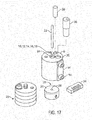
- Figure 19 shows a base jig and other manufacturing aids used to manufacture an embodiment shown in Figures 20A and 20B and described in Example 4.
- sealing device 40 is formed of wires 43.
- Wire frame 40 may be of any size appropriate for an application but is may be sized with outer peripheral edge diameters of 15, 20, 25, or 30 mm.
- the wire frame 40 is formed of continuous wires. Any number of wires may be used to construct the wire frame 40.
- Figures 20A and 20B show a device formed from 5 continuous wires.
- Figure 20A shows a device in a deployed configuration while 20B shows a device in an extended configuration.
- the wire frame 40 may be constructed of wires that have elastic properties that allow for wire frame 40 to be collapsed for catheter based delivery or thoracoscopic delivery, and self-expand to a "memory" induced configuration once positioned in a defect.
- the elastic wire may be a spring wire, or a shape memory NiTi (nitinol) alloy wire or a super-elastic NiTi alloy wire.
- the elastic wire may also be of a drawn-filled type of NiTi containing a different metal at the core.
- Wire frame 40 may be constructed of a drawn-filled type of NiTi wire containing a radiopaque metal at the center. Upon deployment, the wire structure resumes its deployed shape without permanent deformation.
- Wire frame 40 and other wire frames shown are formed from elastic wire materials that have outer diameters between 0.12 and 0.4 mm.
- wire frame 40 comprises a first eyelet 41, a second eyelet 42, a plurality of wires 43, a closed teardrop shape with an internal area 44 and inner peripheral edge 46 and an outer peripheral edge 45.
- the outer peripheral edge 45 is shown as the outermost edge of the wire frame 40.
- the inner peripheral edge 46 of wire frame 40 is illustrated by the inner most edge of the internal area 44 of the closed teardrop shape.
- a wire and closed teardrop shape will nest or interleaf itself between the wire form of the next wire of the device.
- the inner peripheral edge 46 will at least in part center itself within a cardiac defect or other tissue gap.
- the wire frame 40 may be covered with a sealing member as previously described.
- Figure 21 illustrates an embodiment of the wire frame described in example 5.
- the embodiment comprises a proximal 610 and distal eyelet 608 with at least five wires 602, and a self centering waist portion 614 similar to that describe previously in relation to Figure 6 .
- Such an embodiment may be manufactured of similar materials and methods as described previously.
- An alternate embodiment of a sealing device may be made by procuring two sealing device frames and seating one inside the other. Then covering the resulting frame as previously described. Such a device is described in example 6. An embodiment such as this may be manufactured with similar materials and methods as described previously and subsequently described. This technique may be used with any of the wire frames described herein.
- FIG. 22A illustrates a wire frame 51 of a sealing device.
- the embodiment of Fig. 22A comprises a proximal 608 and distal eyelet 610, a plurality of wires 602, wires forming a wire frame 51, a self centering waist portion 614, an reniform shape with an open internal area (not shown) with an inner peripheral edge 54 and an outer peripheral edge 55 .
- the self centering waist portion 614 of this embodiment forms a reniform with an open internal area when in the deployed configuration.
- the outer peripheral edge 55 is shown as the outermost edge of the wire frame 51.
- the inner peripheral edge 54 of wire frame 51 is illustrated by the inner most edge of the open internal area of the reniform shape. In a deployed configuration, the inner peripheral edge 54 will at least in part center itself within a cardiac defect or other tissue gap.
- the wire frame 51 as illustrated in Fig. 22A , has a relatively short extended length prior to deployment.
- a delivery configuration length to deployed radius ratio is about 2.5.
- Such a device may be formed of similar materials as described previously and may be covered with a sealing member also described previously.
- a lock loop 43 (illustrated in Fig. 18A ) may be manufactured separately from the wire frame of the sealing device.
- the lock loop 43 may be formed of any material suitable for forming a sealing device wire frame.
- the lock loop 43 may be made of a different material or have a different wire diameter than that of the sealing device wire frame.
- Lock loop component 43 is manufactured with an eyelet 49 similar to the eyelets of the sealing devices described herein.
- Lock loop 43 may be attached to any sealing device wire frame prior to or post sealing member attachment. Any suitable method of attaching the separate lock loop component to the sealing device may be used. A method of manufacture of a lock loop component is described further in example 9.
- Figures 23A and 23B illustrate an embodiment comprising a proximal 608 and distal eyelet 610, a plurality of wires 52, wires forming a wire frame 61, a self centering waist portion 614, an reniform shape with an open internal area (not shown) with an inner peripheral edge 54 and an outer peripheral edge 55 and a sealing member 604.
- the self centering waist portion 614 of this embodiment forms a reniform with an open internal area when in the deployed configuration.
- the outer peripheral edge 55 is shown as the outermost edge of the wire frame 61.
- the inner peripheral edge 54 of wire frame 61 is illustrated by the inner most edge of the open internal area of the reniform shape.
- the inner peripheral edge 54 will at least in part center itself within a cardiac defect or other tissue gap.
- This embodiment may be constructed with two frames previously described. This embodiment may be constructed of two frames wound in opposite directions or with two frames wound in the same direction. This and the other described wire frames may be constructed with the eyelets configured either as shown or with the eyelets turning toward the center area of the frame along the inner diameter of the device.
- Materials suitable for use as a sealing member 604 have been discussed previously. Sealing member 604 may be attached to the frame in this and other described embodiments as discussed previously. Sealing member 604 in this and other embodiments may be attached to the interior or inner surface of the wire frame and alternately to the exterior of the frame. The sealing member 604 may be attached at only portions of the wire frame leaving certain portions of the wire frame more degrees of freedom of movement. Sealing member 604 might also be attached to cover one side, portions or the entire wire frame 61.
- Figure 23C shows the sealing device embodiment of Figures 23A and 23B with the addition of an opening 605 that is defined by the sealing member 604.
- the opening 605 is configured to provide a fluid communication passageway between the exterior and interior of the sealing device.
- the opening 605 in the sealing member 604 can serve to at least partially prevent or relieve a fluid pressure differential between the interior and exterior of the sealing device.
- the opening 605 can thereby help to maintain the sealing device in a desired position and configuration in relation to the patient's anatomy.
- the opening 605 can include any of the features, traits, configurations, and variations described above in reference to opening 205. While the depicted embodiment includes a single opening 605, in some embodiments two or more openings are defined in the sealing member 604 (e.g., refer to Figure 23D which has two openings 607 and 609). In some embodiments, two, three, four, five, six, seven, eight, nine, ten, eleven, twelve, or more than twelve openings 605 are included in a single sealing device.
- the openings 605 can be disposed on the proximal occlusive disk, the distal occlusive disk, or on a combination thereof,
- the opening 605 can be any of the various sizes, types, shapes, and configurations as described above in reference to the opening 205. It should be understood that the aforementioned various types, shapes, sizes, quantities, locations, configurations, (and so on), of openings 205 and 605 can be combined in all possible permutations and arrangements in the sealing device of Figures 23A-23D , and in any other sealing device embodiment provided herein.
- Figure 23D shows another example embodiment of the sealing device of Figures 23A and 23B with the addition of a first opening 607 and a second opening 609 that are defined by the sealing member 604.
- the openings 607 and 609 can each be individually configured to have any of the features, configurations, and variations as described above in reference to openings 205 and 605.
- the openings 607 and 609 share one or more similar traits (e.g., type, shape, size, similar location, etc.). In some embodiments, the openings 607 and 609 do not share any such similar traits.
- FIG. 25B Another embodiment is shown in Figure 25B .
- This embodiment may be constructed with similar materials as those described previously.
- the embodiment comprises a wire frame 78, first and second eyelets (73 and 75, respectively), a sealing disc 77, a plug region 79 and optionally a sealing member 604 (not shown).
- the embodiment may be constructed of any of the previously described wire frames.
- the sealing disc portion 77 of the embodiment is adapted to cover a wide range of opening sizes while the plug region 79 is adapted to conform to the anatomy into which it is inserted over its entire length. Sealing disc portion 77 has minimal deformation under radial pressure changes or radial pressure exerted upon the plug region 79. Sealing disc 77 and plug region 79 have substantial directional independence due to the flexibility of waist portion 614: that is, the longitudinal axis of the first eyelet 73 may be at significant offset with respect to the longitudinal axis of the second eyelet 75.
- Figure 33 is an end view of an example frame 1700 of an example sealing device 1702.
- Figures 36A and 36B are end views of device 1702, where the device 1702 includes the frame 1700 and a sealing member 1704 attached to the frame 1700.
- Figure 36A depicts a distal occluding member 1714 of the device
- Figure 36B depicts a proximal occluding member 1712 of the device, where the distal and proximal occluding members have a generally disc shape (in a deployed configuration).
- Device 1702 may be used to seal a defect or tissue opening in a body of a patient, and in particular may be used to seal a defect or structure in a heart, such as a septal defect, or to seal other defects or tissue openings discussed herein. In general, the devices discussed herein may aid in substantially sealing such defects or structures. Device 1702 may be delivered to, and deployed at, a defect or tissue opening using the delivery apparatuses or systems described herein, for example. So that the wires 1706 of the frame 1702 may be more clearly shown, sealing member 1704 is not shown in Figure 33 .
- device 1702 includes a delivery configuration and a deployed configuration, where the frame 1700 may be elongated, extended, or collapsed for passage through a delivery apparatus in the delivery configuration.
- Figure 33 and the aforementioned Figures 36A and 36B , each depict the frame 1700 or device 1702 in the deployed configuration.
- Figure 34 is a side view of the example frame 1700 of Figure 33 , where the frame 1700 is shown in a partially elongated state disposed on a mandrel in Figure 34 .
- the embodiment of frame 1700 depicted in Figures 33 and 34 includes eight wires 1706, four of which are labeled in Figure 34 .
- Some embodiments of the frame 1700 include six wires, and embodiments that include any desired number of wires (e.g., four, five, seven, nine, ten, eleven, twelve, or more) are envisioned.
- the wires 1706 of the frame 1700 each extend generally helically from a proximal end of the frame to a distal end of the frame. In general, the wires 1706 may be constructed of any of the materials described herein as pertaining to other wire and frame example embodiments.
- the wires 1706 of the frame 1700 form various features of the frame 1700.
- the frame 1700 includes a first eyelet 1708 near the proximal end of the frame, and a second eyelet 1710 near the distal end of the frame.
- the first eyelet 1708 can be formed from first end portions of the wires 1706
- the second eyelet 1710 can be formed from second end portions of the wires 1706, in some embodiments.
- one or more of the second end portions of the wires may also form a lock loop, as by extending from the eyelet and forming the lock loop.
- Eyelets 1708 and 1710 are examples of wire aggregation elements.
- wire aggregation elements can include hub-like elements that receive and terminate ends of each of the wires 1706.
- frame 1700 includes two wire aggregation elements, generally disposed at or near the proximal and distal ends of the frame, respectively.
- the frame 1700 includes a first occluding member 1712 generally adjacent the first eyelet 1708, and a second occluding member 1714 generally adjacent the second eyelet 1710.
- the first and second occluding members 1712 and 1714 are discs in the deployed configuration, where the discs are generally formed by portions of the wires 1706.
- the first occluding member 1712 includes a first generally linear segment 1716, which may be referred to as a spoke (e.g., a spoke of the first occluding member 1712), and a first generally curved segment 1718, which may be referred to as a rim and a spoke-to-rim transition region, where the first generally linear segment 1716 and the first generally curved segment 1718 together define a petal of the first occluding member 1712.
- the second occluding member 1714 includes a second generally linear segment 1720, which may also be referred to as a spoke (e.g., a spoke of the second occluding member 1714), and a second generally curved segment 1722, which may be referred to as a rim and a spoke-to-rim transition region, where the second generally linear segment 1720 and the second generally curved segment 1722 together define a petal of the second occluding member 1714.
- a spoke e.g., a spoke of the second occluding member 1714
- a second generally curved segment 1722 which may be referred to as a rim and a spoke-to-rim transition region, where the second generally linear segment 1720 and the second generally curved segment 1722 together define a petal of the second occluding member 1714.
- the frame 1700 also includes a defect-occupying portion 1724 disposed between the first occluding member 1712 and the second occluding member 1714.
- the wire 1706 includes, in the defect-occupying portion 1724, a third generally linear segment 1726, a fourth generally linear segment 1728, and a third generally curved segment 1730 disposed between the third generally linear segment 1726 and the fourth generally linear segment 1728.
- the curved segment 1730 provides an inflection region for engaging the defect, as will be discussed in more detail below.
- the curved segment 1730 may be substantially in full contact with the defect or structure when deployed.
- the curved segment 1730 may be in contact with the defect or structure when deployed.
- the curved segment of the inflection region of the defect-occupying portion can have a radius of about 0.094" to about 0.305".
- the curved segment of the inflection region of the defect-occupying portion can have a radius of about 0.094" for a device designed to seal defects of size 8-15 mm; can have a radius of about 0.197" for a device designed to seal defects of size 13-20 mm; can have a radius of about 0.305" for a device designed to seal defects of size 18-25 mm; can have a radius of about 0.300" for a device designed to seal defects of size 23-30 mm; and can have a radius of about 0.302" for a device designed to seal defects of size 28-35 mm.
- Defect sizes can be determined in a number of ways, as is known to those skilled in the art.
- One way of determining defect size is to use a sizing balloon, where a balloon catheter is placed across a defect, the balloon is inflated, and an indentation into the balloon is measured to determine a diameter of the defect. See “ Sizing of Atrial Septal Defects in Adults,” by Hrodmar Helgason et al., Cardiology 2005; 104:1-5 , the entire contents of which is hereby incorporated by reference in its entirety for all purposes. Echocardiography can be used to measure septal length, and a septal defect can be measured using fluoroscopy or echocardiography.
- a contrast-filled, compliant balloon may be placed across the defect and inflated until shunting through the defect has stopped, and the defect size can then be measured using either echocardiography or calibrated fluoroscopy, as will be known to one of skill in the art.
- Figure 33 shows the various wire regions 1716, 1718, 1726, 1730, 1728, 1722, and 1720 labeled for a single wire 1706, while Figure 34 shows some of the wire portions labeled on one wire and others of the wire portions labeled on a different wire.
- Figure 34 also shows a lock loop 1713 and a bumper 1711.
- the lock loop 1713 includes a straight portion of the lock loop and a "pigtail" of the lock loop.
- the lock loop 1713 in not locked in Figure 34 .
- Figure 35 is a side view of the device 1702 in a partially elongated state on a mandrel, where the device 1702 includes the frame 1700 and sealing member 1704.
- Sealing member 1704 may be the same or similar to sealing members discussed elsewhere herein.
- sealing member 1704 may be an ePTFE layer of material, and may be bonded to the frame by an adhesive, such as FEP.
- the one or more portions of the sealing member 1704 may be coated with a hydrophilic material to facilitate imaging of the device and surrounding tissue during implantation.
- Implementations of frame 1700, and generally of device 1702 can be used to seal a wide variety of defect shapes and sizes.
- defects of relatively widely varying defect sizes may be effectively sealed using device 1702.
- some implementations of device 1702 may effectively seal defects having a size range, from largest size to smallest size, where the size range from largest size to smallest size is up to about 7 mm.
- a single device 1702 may be used to seal defects of size 8-15 mm; a single device 1702 may be used to seal defects of size 13-20 mm; a single device 1702 may be used to seal defects of size 18-25 mm; a single device 1702 may be used to seal defects of size 23-30 mm; or a single device 1702 may be used to seal defects of size 28-35 mm.
- the defect occupying portion 1724 is adapted to substantially fill a range of potential defect sizes from a largest defect size to a smallest defect size that is approximately 60% of the largest defect size, and wherein the defect-occupying portion deflects to an outer diameter that is less than about 60% of its nominal outer diameter when a radial pressure of about 0.04 N/mm 2 is applied to the defect occupying portion.
- the device may be configured such that the defect-occupying portion conforms to the shape of the defect, and the occluding members still maintain a generally flat profile (e.g., minimize substantial deviation from the contours of the tissue) on the tissue surface.
- the defect-occupying portion 1724 of the device may be very compliant. For example, when the device 1702 is placed in a defect, the defect-occupying portion 1724 of the device may not substantially deform the defect by pushing against the edge of the defect. Yet, the defect-occupying portion 1724 may still substantially fill the defect for a wide variety of defect sizes and defect shapes. For example, the defect-occupying portion 1724 may deflect based on a radial pressure applied to the defect-occupying portion 1724 by an edge of the defect.
- defect-occupying portion 1724 may not induce “mushrooming” or lifting effects on the occluding member discs of the device, so that the occluding member discs may continue to maintain a generally flat profile and conform to the tissue variances of the respective tissue surfaces that the discs appose.
- Radial stiffness testing wherein a radial pressure is applied to the defect-occupying portion 1724 of the device and a deflection of the defect-occupying portion is measured, has demonstrated the compliance of the defect-occupying portion.
- the defect-occupying portion 1724 of the device deflects to an outer diameter that is less than about 60% of its nominal outer diameter when a radial pressure of about 0.04 N/mm 2 is applied to the defect-occupying portion.
- Measurement of the defect-occupying portion deflection includes measuring a nominal outer diameter of the defect-occupying portion when the device is in a deployed configuration and when substantially zero radial pressure is applied to the defect-occupying portion, applying the radial pressure, and measuring the outer diameter again.
- the outer diameter of the defect-occupying portion can be measured at an inflection region of the defect-occupying portion, and such a diameter may be referred to as an inflection diameter of the device.
- an inflection diameter of the device For example, for a defect-occupying portion 1724 that includes, for each wire of the device, first and second linear sections and a curved section between the linear sections, the nominal outer diameter can be measured across the defect-occupying portion at the curved sections of opposing wires.
- the radial pressure may be applied by a flexible loop of a tensile testing machine, where an adjustable load balance of the testing machine can determine the amount of radial pressure applied by the flexible loop. With 0.04 N/mm 2 of radial pressure applied to the defect-occupying portion 1724, the inflection diameter of the device is reduced to less than about 60% of the nominal inflection diameter, for example, because the defect-occupying portion 1724 is conformable.
- a first device that has a maximal nominal outer diameter of its occluding members of 27 mm, and a maximum nominal diameter of its defect-occupying portion of 17 mm can be used to seal defects of size 8 - 15mm.
- a second device that has a maximal nominal outer diameter of its occluding members of 32 mm, and a maximum nominal diameter of its defect-occupying portion of 22 mm can be used to seal defects of size 13 - 20 mm.
- a third device that has a maximal nominal outer diameter of its occluding members of 37 mm, and a maximum nominal diameter of its defect-occupying portion of 27 mm can be used to seal defects of size 18 - 25mm.
- a fourth device that has a maximal nominal outer diameter of its occluding members of 44 mm, and a maximum nominal diameter of its defect-occupying portion of 32 mm can be used to seal defects of size 23 - 30 mm.
- a fifth device that has a maximal nominal outer diameter of its occluding members of 48 mm, and a maximum nominal diameter of its defect-occupying portion of 36 mm can be used to seal defects of size 28 - 35 mm.
- Figure 36C shows the sealing device 1702 with the addition of openings 1705a and 1705b that are defined by the sealing member 1704.
- the openings 1705a and 1705b are configured to provide a fluid communication passageway between the exterior and interior of the sealing device 1702.
- the openings 1705a and 1705b in the sealing member 1704 can serve to at least partially prevent or relieve a fluid pressure differential between the interior and exterior of the sealing device 1702.
- the openings 1705a and 1705b can thereby help to maintain the sealing device 1702 in a desired position and configuration in relation to the patient's anatomy.
- the openings 1705a and 1705b can individually include any of the features, traits, configurations, and variations described above in reference to openings 205 and 605. While the depicted embodiment includes two openings 1705a and 1705b, in some embodiments other quantities of openings are defined in the sealing member 1704 (e.g., refer to Figure 36D which has four openings 1715a-d). In some embodiments, one, three, four, five, six, seven, eight, nine, ten, eleven, twelve, or more than twelve openings 1705a-b are included in a single sealing device 1702. The openings 1705a and 1705b can be disposed on the first occluding member 1712, the second occluding member 1714, or on a combination thereof,
- the openings 1705a and 1705b can be any of the various sizes, types, shapes, and configurations as described above in reference to the openings 205 and 605. It should be understood that the aforementioned various types, shapes, sizes, quantities, locations, configurations, (and so on), of openings 205 and 605 can be combined in all possible permutations and arrangements in the sealing device 1702, and in any other sealing device embodiment provided herein.
- Figure 36D shows another example embodiment of the sealing device 1702, with the addition of a first opening 1715a, a second opening 1715b, a third opening 1715c, and a fourth opening 1715d that are each defined by the sealing member 1704.
- the openings 1715a, 1715b, 1715c, and 1715d can each be individually configured to have any of the features and variations as described above in reference to openings 205, 605, 1705a, and 1705b.
- two or more of the openings 1715a, 1715b, 1715c, and 1715d share one or more similar traits (e.g., type, shape, size, similar location, etc.).
- the openings 1715a, 1715b, 1715c, and 1715d do not share any such similar traits.
- Figures 37A and 37B show the device 1702 deployed in example defects 1740 and 1742, respectively.
- a first defect 1740 having a dark shade in Figure 37A in contrast to the surrounding lighter shade tissue surface, has a generally circular shape and a relatively smaller defect diameter.
- the diameter of defect 1742 is 28 mm.
- a second defect 1742 having a dark shade in Figure 37B in contrast to the surrounding lighter shade tissue surface, also has a generally circular shape, but has a relatively larger defect diameter.
- the diameter of defect 1740 is 35 mm.
- device 1702 includes one or more radiopaque markers 1744 in the defect-occupying portion 1724 of the device.
- the device 1702 includes four radiopaque markers 1744, one for every other (alternating) wire of the device 1702.
- the radiopaque markers 1744 may be gold bands, in some implementations.
- the radiopaque markers may be crimped on to the wires 1706 in the inflection region of the defect-occupying portion 1724 for ease of device placement verification.
- Three markers 1744 are visible in Figure 37B , and two markers 1744 are visible in Figure 37A (the non-visible markers are obscured by the example tissue in each figure).
- the markers 1744 are resting against the edges of the defects 1740 and 1742, both for the smaller diameter defect 1740 and for the larger diameter defect 1742.
- device 1702 can treat a range of defect sizes without the rims or peripheral edges of the occluding members being substantially raised from the septal tissue. That is, even the rims of the devices may be in contact with tissue surrounding the defect for defects sizes within a treatment range of the device.
- Figure 37B shows a lock loop 1713 that is locked or in a lock-loop-deployed configuration.
- Figure 38 shows the device 1702 deployed in an example defect 1746 having a generally elliptical shape, the defect 1746 having a dark shade in Figure 38 in contrast to the surrounding lighter shade tissue surface.
- Three markers 1744 are visible in FIG. 38 (the non-visible marker being obscured by the example tissue), and as can be seen the markers 1744 are generally resting against the edge of the defect 1746.
- the device 1702 may be used to seal a defect having a generally round shape, a generally elliptical shape, a generally pear shape, a generally triangular shape, a generally square or rectangular shape, a generally polygon shape, a generally semi-circular shape, or generally amorphous shapes.
- Figure 38 also shows that an occluding member need not be centered at the geometric center of a defect, as the eyelet 1710 is generally in the lower half of the defect 1746 along the long axis of the defect, as shown.
- the device may be non-self-centering.
- the occluding members 1712 and 1714 of device 1702 may effectively conform to tissue regions on either side of the defect (e.g., the septal wall on either side of the defect), whether the geometry of such tissue regions is generally flat, or includes a non-flat topography, such as including one or more convex regions, one or more concave regions, or combinations of the foregoing (e.g., ridges or valleys in the tissue surface).
- the occluding members or discs of the device may effectively conform to one or more curvatures of the septum in the area around the defect.
- the occluding member's or members' tendency to conform to the geometry of the surrounding surface, in concert with the defect-occupying portion's compliance and minimal outward radial force application, permits the device to adapt to the defect, including by enabling offset of one or both of the occluding members from a center of the defect (e.g., as shown in Figure 38 ).
- the defect-occupying portion 1724 of the device 1702 may substantially fully occupy the defect and may conform to the size and shape of the defect without imparting a force that is sufficient to cause buckling, lifting, or mushrooming of the occluding members 1712 and 1714 of the device, so that the occluding members 1712 and 1714 may remain in contact with, and provide apposition force against, the respective tissue surfaces (e.g., septal wall surfaces) on each side of the defect.
- the respective tissue surfaces e.g., septal wall surfaces
- FIG. 39 is a three-dimensional view of an example sealing device 1780 deployed in a model 1782 of a portion of a human heart that includes a septum with a tissue surface that includes a curved topography.
- the frame of device 1780 includes six wires.
- the device 1780 is deployed in an atrial septal defect, and the occluding member can be seen conforming to the septum on the right atrium side of the heart, when viewed through the inferior vena cava.
- the occluding member of the sealing device 1780 conforms to the concave curvature of the septal tissue surrounding the defect.
- the occluding members of the device provide an apposition force against the corresponding septal wall and generally assume the topography of the wall surface to substantially seal flat against the wall surface.
- the wires 1706 of frame 1700 are generally arranged such that they can move independently of one another between the eyelets 1708 and 1710. As one wire 1706 or a portion of the wire encounters a geometry of a tissue, for example, the wire or portion of the wire is able to conform to the geometry of the tissue without substantially deflecting or affecting other wires 1706 of the device, in some embodiments. Stated another way, a wire portion or a petal of the first occluding member is adapted to bear a load associated with a first tissue surface without imparting a substantial force to the other wires of the device.
- a wire portion or a petal of the second occluding member is adapted to bear a load associated with a second tissue surface without imparting a substantial force to the other wires of the device.
- a first petal e.g., of the first occluding member
- a second petal e.g., of the second occluding member
- a load associated with a second tissue surface may not impart a substantial force to other petals (e.g., other petals of the second occluding member).
- a given wire 1706 forms a petal of the first occluding member and also forms a petal of the second occluding member, and in general the petal of the first occluding member may move substantially independently from the petal of the second occluding member, and the petal of the second occluding member may move substantially independently from the petal of the first occluding member.
- the petals may move generally independently from one another, and even for petals formed from the same wire (e.g., where one petal forms a portion of the proximal disc and the other petal forms a portion of the distal disc), the petals may generally move or conform to the tissue substantially independently from one another.
- a movement of one wire may not directly translate to a movement of one or more other wires of the device. Stated another way, a given wire is able to bear a load generally without substantially affecting other wires of the device.
- the final position of the device may be primarily driven by the occluding member 1712 and 1714 interactions with the tissue surfaces around the defect, and only minimally or substantially not driven by the defect-occupying portion's 1724 interface with the interior wall of the defect.
- the defect-occupying portion 1724 or a portion thereof e.g., the curved segment or only a portion of the curved segment
- the device may be configured such that the defect-occupying portion conforms to the shape of the defect and the occluding members still maintain a generally flat profile (e.g., minimize substantial deviation from the contours of the tissue) on the tissue surface.
- the occluding members may occupy a smaller volume within the atrium as compared to other sealing devices where mushrooming of the discs can be a problem for some defects. Maintaining a flat profile also may facilitate better incorporation of the device into native tissue via a tissue ingrowth process, for example.
- the devices shown in Figures 33-39 and described above are able to substantially seal a defect or structure in a heart of a patient, and to substantially occupy the defect or structure, based on a combination and interrelation of device properties that cooperate in a synergistic manner.
- a structure and orientation of the elongate elements including, e.g, the structure and orientation of the various portions or regions of the elongate elements, work together to provide for a stable placement of the device, while maintaining a profile that approximates the respective tissue surfaces on either side of the defect or structure.
- Figure 40 is a lateral view of a single wire 1790 of a six-wire device, such as device 1780 of Figure 39 , in a deployed configuration.
- Figure 41A is an end view of a single wire 1706 of example frame 1700.
- the proximal and distal eyelets are aligned longitudinally, so that the distal eyelet is immediately below the labeled proximal eyelet 1708.
- Figure 41A shows that an angle defined by the wire's exit from the proximal eyelet 1708 and the wire's entry to the distal eyelet is about 150 degrees, or in some embodiments in a range from about 150 degrees to about 152 degrees.
- frame 1700 includes eight wires 1706.
- each of the device's wires when viewed individually, may define one of the aforementioned angles between the respective wire's exit and entry points. For each of the occluding members of the device, adjacent petals formed by the individual wires and corresponding to a particular occluding member will overlap one another.
- Figure 41B is an end view of a single wire 1790 of the frame of example device 1780.
- Figure 41B shows that an angle defined by the wire's exit from the proximal eyelet and the wire's entry to the distal eyelet is about 210 degrees, or in some embodiments in a range from about 210 degrees to about 214 degrees.
- the angle defined by the aforementioned wire exit and entry points to the eyelets is about 212 degrees; for a device sized to occlude a defect with a size of 13-20 mm, the angle defined by the aforementioned wire exit and entry points to the eyelets is about 214 degrees; and for a device sized to occlude a defect with a size of 18-25 mm, the angle defined by the aforementioned wire exit and entry points to the eyelets is about 210 degrees.
- the frame for device 1780 includes six wires 1790.
- each of the device's wires when viewed individually, may define one of the aforementioned angles between the respective wire's exit and entry points.
- adjacent petals formed by the individual wires and corresponding to a particular occluding member will overlap one another.
- Figure 42 shows the device 1702 in a deployed configuration, where the device 1702 includes a non-metal attachment member 1796.
- Non-metal attachment member 1796 may be an ePTFE loop attached to an eyelet of the device 1702, for example.
- a retrieval cord 1798, which may comprise an ePTFE tether, of the delivery apparatus 1799 is looped through the non-metal attachment member 1796.
- the device 1702 can be fully deployed while remaining coupled to the delivery apparatus 1799, so that an assessment of the deployment under a lower tension or tension-free (as compared to the device being more rigidly secured to the delivery apparatus) may be performed.
- the device 1702 can be recaptured by the delivery apparatus 1799 by drawing the device 1702 into the apparatus using the retrieval cord 1798.
- fraying of the retrieval cord 1798 may be minimized or avoided because of the non-metal-on-non-metal interface of retrieval cord 1798 and non-metal attachment member 1796.
- non-metal attachment member 1796 and retrieval cord 1798 can comprise any biocompatible material of sufficient strength and flexibility.
- a metal attachment member can be used.
- the retrieval cord 1798 is looped through an eyelet of the device 1702.
- Some embodiments include left and right discs interconnected by a defect occupying region.
- the discs may be soft and conformable, and the nominal diameters of the left and right discs may be substantially equivalent.
- the device may be preassembled to a delivery system.
- the devices may include fewer than ten Niti wires.
- the devices may include a small amount of metal mass.
- the devices may be versatile. For example, defect size ranges from 8 mm to 35 mm, such as for atrial septal defects, and more specifically for ostium secundum atrial septal defects, may be treated with five device sizes, in some implementations.
- the devices may be deployed by a handle deployment system with simple push/pull motions for loading and deployment. In some embodiments, the metal frame of the device may not be exposed to the bloodstream.
- a delivery catheter with both multi-purpose and Hausdorf-type curves may be used.
- a 10 Fr. (outer diameter) catheter may be used.
- An 11 Fr. (outer diameter) catheter may be
- the sealing devices described herein may be implanted using a percutaneous, transcatheter procedure.
- the sealing device may be loaded or attached to a delivery apparatus, for example as described above herein.
- the sealing device may be loaded or attached to a delivery catheter that is controlled by a control handle, for example.
- the delivery apparatus may be advanced to a location of defect or structure in a heart of a patient, and the sealing device may be deployed at the location of the defect or structure to seal the defect or structure.
- the defect or structure may be an atrial septal defect.
- the defect or structure may be an ostium secundum defect.
- the defect or structure may be a patent foramen ovale defect.
- the sealing device may be attached or loaded to a delivery catheter, which may be advanced over a guidewire across the atrial septum until the tip of the delivery catheter is positioned within the left atrium.
- the guidewire may be removed.
- a first action at a handle of a delivery system that is coupled to the delivery catheter may deploy the left occluding member (e.g., left disc) of the sealing device from the catheter.
- the first action may include moving a slider control on the handle in a first direction until the slider control encounters a stop. This action may be performed simultaneously with retracting the delivery catheter a distance.
- the first action may also include moving the slider control in a second direction that is different from the first direction (e.g., perpendicular to the first direction) and then again in the first direction until a tactile cue at the handle is encountered, which may indicate to an operator that the left occluding member has been deployed.
- the operator may give the handle a gentle tug to bring the left occluding member into contact with the left atrial septum.
- a second action at the handle may deploy the right occluding member (e.g., right disc).
- the second action may include moving the slider control in the first direction until the slider control encounters a stop, and then moving the slider control in a third direction that is different from the first and second directions (e.g., opposite of the second direction).
- a third action at the handle may cause the sealing device to be locked into place at the delivery location, as by locking the lock loop of the device.
- any of the sealing devices discussed herein may also be formed from a tube, such as laser-cut from a Nitinol tube.
- a laser may be used to cut a pattern into a hollow tube to create a sealing device that resembles the wire-wound sealing devices discussed herein, where portions of the tube remaining after the pattern has been cut may correspond to the elongate elements or wires of the devices discussed herein.
- a Nitinol tube having an outer diameter sized to correspond to the eyelet or elongate element aggregation elements discussed herein may be laser-cut in this manner, for example.
- eyelets or wire aggregation elements at or near the proximal or distal ends of the device
- one or both eyelets or wire aggregation elements may be oriented toward the center of the device rather than toward the proximal or distal ends of the device.
- devices that include eyelets oriented toward the center of the device, or for other styles of wire aggregation elements which may be used to replaced, e.g., eyelets or wire aggregation elements discussed herein
- FIG. 1 One of the example sealing devices discussed herein have generally been described as including eyelets or wire aggregation elements at or near the proximal or distal ends of the device
- one or both eyelets or wire aggregation elements may be oriented toward the center of the device rather than toward the proximal or distal ends of the device.
- wire aggregation elements which may be used to replaced, e.g., eyelets or wire aggregation elements discussed herein
- wire aggregation elements or hub elements which may be used to replaced, e.g., eyelets or wire aggregation elements discussed herein
- provisional patent application titled "Joint Assembly for Medical Devices” having inventors Coby C. Larsen, Steven J. Masters, and Thomas R. McDaniel, filed on 16 November 2012, assigned U.S. Ser. No. 61/727,328
- non-provisional patent application titled "Joint Assembly for Medical Devices” having inventors Coby C. Larsen, Steven J. Masters, and Thomas R. McDaniel, filed on 15 March 2013, the disclosures of which are considered part of and are specifically incorporated by reference in their entirety (including the figures) for all purposes in the present disclosure.
- Anchor components or fixation devices may be attached to any of the embodiments. Examples of anchor complements (80 and 96) are shown in Figures 26A and 30 .
- Figure 26A illustrates an anchor component 80 with fixation elements configured to pierce, puncture or protrude into tissue adjacent to the device during or after deployment.
- Anchor component 96 in Figure 30 illustrates fixation elements configured with blunt ends designed to grasp or engage the adjacent tissue without substantially protruding into the tissue.
- Other anchor components may be envisioned, including anchor components configured to possess both piercing and grasping capabilities.
- Anchor component may be similar to that shown in Figure 30 , but instead of having looped wire arm, have a single wire arm with a looped end, the end of which may be crimped or positioned to either be in the same plane as the single wire arm or to protrude from the plane thereby being available to pierce or puncture tissue.
- Anchor components may be attached at any eyelet of the device. Anchor components may be configured to bend in any direction.
- Single or multiple anchor components may be affixed to any device or wire frame in any combination. Said anchors can be designed to release the tissue for repositioning and/or retrieval. Further, when the sealing device is in a delivery configuration, the barbs may be collapsed to avoid catching on the catheter components during retrieval of the device.
- Figure 8 shows a perspective view of sealing device 100 attached to a delivery system including first tube102, third tube 104, and a handle for deploying a sealing device 100.
- Figure 8 further illustrates a fist linear actuator 802, a flushing port 804, the second linear actuator 806, lock release actuator 808, a housing 810 and a slot with a length in the housing 812.
- First linear actuator 802 may have a variety of configurations, which will be discussed further.
- Figures 9A-D are flow charts which describe the movements of the various components of the delivery system and attached sealing device 100 during use. Loading sealing device 100 into the delivery system prior to use is described in Figure 9A . Components of the delivery system handle are shown in Figures 8 , 10 and 11 . A clinician may flush the delivery system by attaching a syringe or other suitable implement onto flushing port 804 and filling the system with saline or any other appropriate flushing material. The first linear actuator 802 may then be moved in slot 812 in housing 810 against a spring 1100.
- Spring 1100 may be configured as shown or may be formed as a leaf spring, stepped spring or any form commonly known in the arts.
- Sizing insert 1103 may be of any material with suitable mechanical properties.
- Typical handles, handle components, tools or catheters used to deliver medical devices can comprise commonly known materials such as Amorphous Commodity Thermoplastics that include Polymethyl Methacrylate (PMMA or Acrylic), Polystyrene (PS), Acrylonitrile Butadiene Styrene (ABS), Polyvinyl Chloride (PVC), Modified Polyethylene Terephthalate Glycol (PETG), Cellulose Acetate Butyrate (CAB); Semi-Crystalline Commodity Plastics that include Polyethylene (PE), High Density Polyethylene (HDPE), Low Density Polyethylene (LDPE or LLDPE), Polypropylene (PP), Polymethylpentene (PMP); Amorphous Engineering Thermoplastics that include Polycarbonate (PC), Polyphenylene Oxide (PPO), Modified Polyphenylene Oxide (Mod PPO), Polyphenelyne Ether (PPE), Modified Polyphenelyne Ether (Mod PPE),Thermoplastic Polyurethane (TPU); Semi-
- a distal notch 1104 and proximal notch 1106 in sizing insert 1103 may be used to aid in the positioning of the first linear actuator 802 in housing slot 812.
- the distance between the two notches, 1104 and 1106 respectively, may be the length of sealing device 100 when it is elongated over second tube 108 prior to loading onto the delivery system.
- Sizing insert 1103 may be sized to accommodate a variety of device lengths and is preferably from about 22.28 cm long with a distance between the proximal end of distal notch 1104 and proximal end of proximal notch 1106 from about 6.25-13.32 cm.
- Notches 1104 and 1106 may be of any shape but are preferably rectangular.
- First linear actuator 802 is then moved to a mid point in slot 812 toward the proximal end of the housing 810. This action causes the first tube 102 to move proximally and the sealing device 100 proximal end to move proximally, thus elongating sealing device 100.
- First linear actuator 802 may be any shape (e.g., lever, ball) but is preferably shaped to accommodate a clinician's thumb.
- First linear actuator 802 may be constructed of any material with suitable mechanical properties but is preferably a material similar to that of sizing insert 1103.
- a feature of the first linear actuator 802 are recessed teeth formed in the top portion of the first linear actuator 802 for securing retrieval cord 110. This feature is preferred but optional.
- the teeth could be made into any tortuous path or have any shape desired to create resistance for retrieval cord 110 during loading, deployment, or retrieval of sealing device 100.
- Corresponding protruding teeth may be formed in the bottom surface of retrieval cord lock 803. These teeth may fit together and hold the retrieval cord firmly.
- Other methods commonly known in the art for securing a small diameter cord may also be used and will be discussed in detail in a following section.
- the first linear actuator 802 is then moved further proximally until the device is loaded in third tube 104. During this action, spring 1100 pushes the first linear actuator 802 and the mandrel control lever 1000 to the left of slot 812 and into the proximal notch 1106 in sizing insert 1103.
- the second tube 108 is free to move proximally with sealing device 100 and first tube 102.
- the first linear actuator 802 is moved proximally, the second tube 108, sealing device 100 and first tube 102 slide or translate into the third tube 104.
- the system may again be flushed with saline in the manner described above.
- first linear actuator 802 is shown in Figures 12A-D .
- Figure 12A shows a perspective view of the alternate linear actuator 1108 in the locked retrieval cord position.
- Linear actuator 1108 is similar in construction to linear actuator 802 but features a retrieval cord locking ring 1110 and retrieval cord groove 1112.
- Figure 12B depicts alternate embodiment 1114, which is configured with a thumb wheel 1116 that extends beyond the sides of the linear actuator to facilitate easy manipulation. Thumb wheel 1116 is screwed onto a threaded post 1118 around which the retrieval cord is wound.
- Embodiment 1114 also contains a retrieval cord groove 1120 through which the retrieval cord is guided prior to securing it around threaded post 1118.
- Figure 12C illustrates yet another embodiment 1122 that utilizes a side fitted threaded thumb wheel 1124 around which the retrieval cord is wound and secured to the actuator 1122 by the act of inserting the threaded post 1124 into a threaded aperture (not shown) in the side of the actuator 1122.
- the retrieval cord Prior to winding the retrieval cord around the threaded post 1124, the retrieval cord is inserted through the retrieval cord groove 1126.
- Yet another embodiment 1128 is shown in Figure 12D .
- Embodiment 1128 shows a linear actuator with molded thumb wheel 1130.
- the thumb wheel 1130 extends slightly beyond the edges of the linear actuator facilitating manipulation of the linear actuator.
- the retrieval cord is inserted through cord groove 1132 and wound around a threaded post (not shown).
- the molded thumb wheel 1130 is then secured on the threaded post securing the retrieval cord.
- FIG. 9B Deploying sealing device 100 into a defect is described in Figure 9B .
- the first linear actuator 802 is moved distally until a stop is reached. This movement causes the first tube 102 and second tube 108 to move distally within the third tube 104.
- the linear actuator 802 must then be moved to the right in slot 812, against spring 1100.
- mandrel control lever 1000 rotates on slider rod 1102. This action causes the linear actuator 802 to be free of the proximal notch 1106 in sizing insert 1103. After this action, the linear actuator 802 is further translated distally. This causes the first tube 102 and proximal eyelet 202 of sealing device 100 to move distally.
- sealing device 100 Also affected by this action is the distal end of sealing device 100, which is prevented from moving.
- the first tube 102 guides the device out of the third tube 104 to deploy the device in a defect.
- Moving linear actuator 802 distally to the end of slot 812 results in the entire sealing device being deployed.
- the retrieval cord lock 803 would be unsnapped from the first linear actuator 802.
- a clinician would grasp the second linear actuator 806 by gripping attached lock release actuator 808 and press it toward the middle of housing 810.
- the second linear actuator 806 may be of any size or shape but is preferably sized to fit within a slot 1002 in the longitudinal surface of housing 810.
- Linear actuator 806 is fitted with lock release actuator 808 by means of a snap fitting. Any means of attachment would suffice to fasten lock release actuator 808 to linear actuator 806, such as glue or construction as a molded part.
- Lock release actuator 808 is designed to enable a user to grip the device securely. Gripping may be aided by protrusions on the lateral sides of the lock release actuator 808. These protrusions may be made of a similar material as that of the lock release actuator 808, or may be made of a material with a high coefficient of friction or of a material more compliant than that of lock release actuator 808. These protrusions may also be made with grating, a roughening, a raised design, or striations in the surface in conjunction with the material listed above to further aid in the gripping of the device.
- Slot 1002 may be configured to have a stop to hold the second linear actuator 806 in a distal most position until lock release of the sealing device.
- a preferred stop is shown in Figures 10 and 11 in the form of a corrugated area, but may also be any manner of mechanical stop.
- Slot 1002 may be of any length, but preferably has a length sufficient to translate motion proximally about the width of the second linear actuator 806 plus about 3.18 cm. Slot 1002 may be any shape that would accommodate the second linear actuator 806.
- FIG. 13A and 13B An alternate embodiment of second linear actuator 806 is shown in Figures 13A and 13B .
- a rotatable lock release actuator 1300 is gripped and rotated to affect lock release.
- the rotatable lock release actuator 1300 may contain a window 1302, which would prevent forward movement of the first linear actuator 802. When rotated, lock release actuator 1300 allows the same actions as lock release actuator 806 shown in Figure 10 .
- Second linear actuator 808 moves proximally. This action results in proximal movement of third tube 104, mandrel control lever 1000, sizing insert 1103 and second tube 108. Second tube 108 moves proximally from between eyelets of the device.
- An alternate method of achieving this action would be to provide a twist mechanism to the distal end of the handle instead of a second linear actuator 806. This twist mechanism would be provided with a slot that allows for the same movement of the third tube 104, mandrel control lever 1000, sizing insert 1103 and second tube 108 as the second linear actuator 806.
- Retrieval cord 110 is attached to the retrieval cord lock 803 at one end.
- Retrieval cord 110 may be constructed of any material with suitable mechanical properties such as Kevlar®, flexible metal wire, polymers and the like.
- a preferred material for retrieval cord 110 is an ePTFE fiber.
- Retrieval cord lock 803 may be configured in a variety of shapes and sizes. Possible retrieval cord locks may be designed to provide a slot in the linear actuator 802 through which the retrieval passes.
- the retrieval cord is secured by passing the cord through a slot or hole in the axis of the thumb wheel disposed in the linear actuator 802 and tightened by twisting the thumb wheel.
- An alternate configuration would provide a slide lock that binds the retrieval cord between the lock and the linear actuator 802 using friction.
- a preferred design would be to secure the retrieval cord between teeth formed in the retrieval cord lock as shown in Figure 11 .
- retrieval cord lock 803 Materials suitable for constructing retrieval cord lock 803 are similar to that used to construct housing 810 and other handle components. As mentioned previously, retrieval cord lock 803 preferably has teeth or protrusions that correspond to indentations in linear actuator 802 for the purpose of gripping retrieval cord 110. Retrieval cord lock 803 may be configured in a variety of shapes to enable retrieval cord 110 to be secured. A preferred configuration would include apertures through the retrieval cord lock 803 to allow retrieval cord 110 to be passed therethrough and knotted. After twisting the retrieval cord lock 803, it is pulled until the retrieval cord 110 is removed from the delivery system.
- the sealing device 100 may be retrieved as described in the flowchart illustrated in Figure 9D .
- the retrieval cord lock 803 may be snapped into the first linear actuator 802. This serves to lock the retrieval cord 110 in place.
- the clinician then moves the first linear actuator 802 to the right edge of slot 812.
- the first linear actuator 802 moves in slot 812 to the right, pressing on spring 1100 while the mandrel control lever 1000 rotates on the slider rod 1102 to the right of the handle.
- Slider rod 1102 is preferably of a round cross-section but one skilled in the art would recognize that a variety of cross-sectional shapes (e.g., square or triangular) would be acceptable.
- Slider rod 1102 could also be configured in the shape of a crown spring 1400, as shown in Figures 14A and B .
- the spring could be inserted in a slot 1402 through the linear actuator to allow fore and aft translation of the linear actuator.
- An alternate embodiment of spring 1100 may be a spring molded as an integral part 1500 of first linear actuator 802, as illustrated by Figure 15 .
- Another embodiment of spring 1100 is shown in Figure 16 . In this configuration, a spring 1600 is attached to housing 810 and pushes on the first linear actuator 802 in key positions. As stated above, one skilled in the art would recognize the appropriate materials for use as a spring or molded part.
- the first linear actuator 802 is free of distal notch 1104 and the second tube 108 is prevented from moving.
- the first linear actuator is moved proximally by the clinician, causing first tube 102 to move proximally. This motion translates the proximal end of sealing device 100 proximally elongating the device 100 and allowing it to be pulled into the third tube 104.
- a sealing device similar to Figure 1 was manufactured using the following components and assembly process.
- Methanol bubble point was measured using a custom built machine with a 1 inch diameter foot, a ramp rate of 0.2 psi/second and a liquid media of methanol.
- Length and width of the material were measured using a metal ruler.
- Mass/area was measured using a balance (Model GF-400 Top Loader Balance, ANG, San Jose CA.) with a 36 x 5 inch sample.
- Longitudinal maximum load was measured using a materials test machine (Model 5564, Instron, Grove City, PA) equipped with a 10 kg load cell. The gauge length was 1 inch and the cross head speed was 25mm/minute. Sample width was 1 inch.
- Material was weighed using a precision analytical balance (Model GF-400 Top Loader Balance, ANG, San Jose CA.) with a sample area of 36 x 1 inch sample. Length and width of the material were measured using a metal ruler. Material thickness was measured using a digital thickness gauge (Mitutoyo Digital Indicator 547-400) with a foot diameter of 1 ⁇ 4 inch. Maximum transverse load was measured using a materials test machine (Model 5564, Instron, Grove City, PA) equipped with a 10kg load cell. The sample width was 1 inch, the gauge length was 1 inch and the cross head speed was 25mm/minute.
- a distal eyelet was formed by first obtaining a length of 10% platinum drawn filled nitinol wire (Fort Wayne Metals, Fort Wayne, IN.) with a diameter of about 0.23 mm. This wire was labeled "first wire”. A free end of the first wire was doubled on itself to create an open-ended loop and the open-ended loop was inserted into the button. The button was then inserted onto the keyed center pin. The button was shaped to have an opening through the center to accommodate the keyed center pin and to have features that allow it to rest securely in the winding jig.
- the keyed center pin (major axis of about 0.51 mm and minor axis of about 0.25 mm and length of about 10.16 mm) was then inserted in the center of a winding jig.
- the keyed center pin was fabricated from high strength steel (Super Cobalt HSS Tool Bit, MSC#56424278, Seco Fagersta). The steel was tempered per manufacture's instructions at 1475° F for one hour.
- the winding jig and button were fabricated in house from corrosion resistant tool steel.
- a second length of the same type of drawn filled nitinol wire was obtained and labeled "fifth wire".
- the first, fifth and an additional three wires were tensioned by attaching weights to the wire ends.
- the first wire and the fifth wire were then wound around the free end of the first wire one full revolution.
- the three additional wires were introduced to the winding jig and all five wires were wound around the free end of the first wire to a height of about 1.98 mm.
- a distal disk was then formed by separating the five wires and securing them in radial grooves around the circumferential edge of the winding jig.
- a radius was formed with the dimensions of 15 mm.
- Each wire formed one petal of the distal disk.
- the radius on the curvature of the petals was maximized in order to minimize sharp bend angles in the wire.
- a center eyelet was formed by grouping the wires together and winding them around the free end of the first wire and the keyed center pin to a height of about 1.98 mm. The wires were then separated and secured in radial grooves around the circumferential edge of the winding jig, creating a proximal disk with a radius of 15 mm.
- a proximal eyelet was formed by again grouping the five wires and winding them around the free end of the first wire and the keyed center pin to a height of about 1.98 mm.
- the five wires were then separated and secured by placing a stainless steel plate on top of the wires and locking down the plate with screws.
- the free end of the first wire was then wound one revolution around a stainless steel pin with a diameter of about 3.18 mm and secured similarly to the other five wires.
- the jig with sealing device was then removed from the stabilizing fixture and placed in an oven (BlueM SPX Electric Forced Air Convection Oven), and the wires were thermally shape set as commonly known in the arts.
- the device and jig were then water quenched.
- the secured wires were released from the securing plate, and the device was chilled and removed from the jig and keyed center pin.
- the device was then placed on a piece of flattened PEEK (polyetherether ketone), and trimmed by hand to the outer diameter of the distal eyelet.
- the lock loop was trimmed by hand to a point just beyond one complete revolution and pulled through the proximal and center eyelets.
- the device was pushed from the PEEK mandrel onto a keyed stainless steel process mandrel with an oval cross section.
- the mandrel was produced from flattened stainless steel wire (Ft. Wayne Metals, Fort Wayne, IN) with an oval cross-section to have a 45° clockwise twist between the proximal eyelet and the center eyelet and a second 45° clockwise twist between the center eyelet and the distal eyelet.
- the process mandrel and device were then placed in a stabilizing fixture, which was placed in a FEP powder coating machine (C-30, Electrostatic Technology, Inc., Bradford, CN) and processed until coated completely. Excess FEP powder was removed from the device. The FEP was vacuumed from the lock loop, process mandrel and bumper. The process mandrel and device were removed from the stabilizing fixture, placed into an oven and baked to set the FEP coating, as commonly known in the arts.
- a FEP powder coating machine C-30, Electrostatic Technology, Inc., Bradford, CN
- a hollow core film mandrel (35.99 mm O.D. 76.2 cm long stainless steel) was obtained. Expanded polytetrafluoroethylene material with a slit width of 22.22 mm was obtained and loaded onto a spiral wrapping machine. The machine was manufactured in house to wrap PTFE (polytetrafluoroethylene) material at any desired angle, tension and rate. The mandrel was loaded onto the wrapping machine and the material was wrapped three times around the circumference of the hollow core mandrel. The material was then wrapped around the mandrel at an angle of about 8°for the length of the mandrel. The direction of wrapping was reversed and the material over wrapped at the same angle. The third and fourth layers were wrapped in the same manner with the seams offset. The mandrel was removed from the wrapping machine, inserted in an oven and baked at 370° C for 45 minutes. The wrapped mandrel was removed from the oven and allowed to cool to room temperature. The resulting PTFE tube was removed from the mandrel.
- the PTFE tube was then cut to about 140 mm and hand stretched to a desired length of 155 mm. The PTFE tube was then pulled over the frame. The PTFE tube was then crimped onto the center eyelet and then crimped onto the distal and proximal eyelets.
- FEP fluorinated ethylene propylene
- a sealing device similar to Figure 6 was manufactured using the following components and assembly process.
- Expanded polytetrafluoroethylene and expanded polytetrafluoroethylene with a thin layer of FEP (fluorinated ethylene propylene) materials similar to that described in Example 1 were obtained.
- a distal eyelet was formed by first obtaining a length of 10% platinum drawn filled nitinol wire (Fort Wayne Metals, Fort Wayne, IN.) with a diameter of about 0.23 mm. This wire was labeled "first wire”. A free end of the first wire was doubled on itself to create an open-ended loop, and the open-ended loop was inserted into the button. The button was then inserted onto the keyed center pin. The button was shaped to have an opening through the center to accommodate the keyed center pin and to have features that allow it to rest securely in the winding jig.
- the keyed center pin (major axis of about 5.79 mm and minor axis of about 0.25 mm and length of about 10.16 mm) was inserted in the center of a winding jig.
- the keyed center pin was fabricated from high strength steel (Super Cobalt HSS Tool Bit, MSC#56424278, Seco Fagersta).
- the winding jig and button were fabricated in house from corrosion resistant tool steel.
- a second length of the same type of drawn filled nitinol wire was obtained and labeled "fifth wire".
- the first, fifth and an additional three wires were tensioned by attaching weights to the wire ends.
- the first wire and the fifth wire were then wound around the free end of the first wire one full revolution.
- the three additional wires were introduced to the winding jig, and all five wires were wound around the free end of the first wire to a height of about 1.98 mm.
- a device was then formed by separating the five wires and securing them in radial grooves around the circumferential edge of the winding jig.
- a radius was formed with the dimensions of 15 mm.
- Each wire made an entire revolution around the winding jig.
- a proximal eyelet was formed by grouping the five wires and winding them around the free end of the first wire and the keyed center pin to a height of about 1.981 mm.
- the five wires were then separated and secured by placing a stainless steel plate on top of the wires and locking down the plate with screws.
- the free end of the first wire was then wound one revolution around a stainless steel pin with a diameter of about 3.18 mm and secured similarly to the other five wires.
- the jig with sealing device was removed from the stabilizing fixture and placed in an oven (Blue M SPX Electric Forced Air Convection Oven), where the wires were partially thermally shape set as commonly known in the arts.
- the device and jig were then water quenched.
- the secured wires were released from the securing plate, and then the device was chilled and removed from the jig and keyed center pin.
- the lock loop was trimmed by hand to a point just beyond one complete revolution and pulled through the proximal and center eyelets.
- the device was pushed from the PEEK mandrel onto a keyed stainless steel transfer mandrel with an oval cross section.
- the mandrel was produced from flattened stainless steel wire (Ft. Wayne Metals, Fort Wayne, IN) with an oval cross-section.
- the device was then partially removed from one end of the transfer mandrel. The removed device end was twisted approximately 180° clockwise and repositioned on the transfer mandrel.
- the device and transfer mandrel were placed in an oven (Blue M SPX Electric Forced Air Convection Oven), where the wires were thermally shape set as commonly known in the arts.
- the transfer mandrel and device were then placed in a stabilizing fixture, which was placed in a FEP powder coating machine (C-30, Electrostatic Technology, Inc., Bradford, CN) and processed until coated completely. Excess FEP powder was removed. FEP powder was vacuumed from the lock loop, process mandrel and bumper. The transfer mandrel and device were then removed from the stabilizing fixture, placed into an oven and baked to set the FEP coating, as commonly known in the arts.
- a FEP powder coating machine C-30, Electrostatic Technology, Inc., Bradford, CN
- a hollow core film mandrel (35.99 mm O.D. 76.2 cm long stainless steel) was obtained.
- An ePTFE material with a slit width of 22.24 mm was obtained and loaded onto a spiral wrapping machine.
- the machine was manufactured in house to wrap ePTFE film at any desired angle, tension and rate.
- the mandrel was loaded onto the wrapping machine and the film was wrapped three times around the circumference of the hollow core mandrel.
- the ePTFE material was then wrapped around the mandrel at an angle of about 8° for the length of the mandrel.
- the direction of wrapping was reversed and the material over wrapped at the same angle.
- the third and fourth layers were wrapped in the same manner with the seams offset.
- the mandrel was removed from the wrapping machine, inserted in an oven and baked at 370° C for 45 minutes.
- the wrapped mandrel was removed from the oven and allowed to cool to room temperature.
- the resulting ePTFE tube was removed from the mandrel.
- the ePTFE tube was then cut to about 140 mm and hand stretched to a desired length of 155 mm. The ePTFE tube was then pulled over the frame. The ePTFE tube was then crimped onto the distal and proximal eyelets. An ePTFE with a thin layer of FEP (fluorinated ethylene propylene) material was then wrapped four times around the eyelets. The wrapped eyelets were tacked into place using a soldering iron. The ePTFE tube was then heat set for 3 minutes at 320° C and trimmed to the outer most points of the proximal and distal eyelets. The device was then removed from the mandrel.
- FEP fluorinated ethylene propylene
- Components for the handle assembly were fabricated using an injection molding process.
- the parts were fabricated by Contour Plastics (Baldwin, WI) using Lustran® 348. This material was suitable for use in medical devices and has an advertised tensile strength of 48.2 MPa and a tensile modulus of 2.62 GPa.
- the parts included the second linear actuator, flushing gasket retainer, a first linear actuator, retrieval cord lock, mandrel control lever, left body housing, sizing insert, right body housing, and a lock release actuator.
- a catheter tube formed with a layup process commonly known in the arts was ordered (Teleflex Medical, Jaffrey, NH) with an I.D. of 0.048 mm and an O.D. of 0.33 mm and a platinum iridium marker band placed near the end of the distal tip.
- the main body of the catheter tube was Pebax® 7233 tube with PTFE liner and stainless steel braid (65 PPI) and the distal most 20.32 mm of the catheter tube was comprised of 6333 Pebax®(0.027 mm I.D. and an 0.033 mm O.D.) and a curve in the distal end (39.98 mm radius).
- a guidewire port formed by a laser was placed in the catheter tube proximal of the marker band.
- a flushing gasket or u-cup type gasket made of silicone (22.99 mm depth, I.D. tapered from 2.89 mm to 1.85 mm I.D. tapered from 6.71 mm to 7.75 mm) was procured from Apple Rubber of Lancaster, NY.
- a flushing port (Merit Medical, South Jordan, UT) having an about six inch flexible pvc (polyvinyl chloride) tube with a 3.18 mm O.D. female luer connector was obtained.
- a quick set cyanoacrylate adhesive was supplied from in-house stock. Stainless steel hypotubes were ordered from Small Parts, Inc.
- Slider rods (PTFE coated stainless steel hypotubes, 3.18 mm O.D., 1.65 mm I.D., length of 33.02 cm) were procured from Applied Plastics.
- Control springs (PTFE-coated stainless steel leaf springs, thickness 0.10 mm, minor flange length 5.33 mm, major flange length 10.11 mm, overall length 15.88 mm) were ordered from Incodema of Ithaca, NY.
- triple lumen tubes were manufactured of Pebax® 7233 with 20% barium sulfate. Both triple lumen tubes had an O.D. (outer diameter) of 0.25 mm. One triple lumen tube had round lumens with two I.D.s (inner diameters) of 0.035 mm and one I.D. of 0.15 mm. One triple lumen tube had one lumen with an oval cross-section with two I.D.s of 0.036 mm and one I.D of 0.127 x 0.07 mm. Stainless steel PTFE coated (polytetrafluoroethylene) process mandrels were manufactured in house.
- One process mandrel had a cross-sectional shape that transitioned from round (O.D. of 0.16 mm) to oval (O.D. of 0.14 x 0.07 mm).
- PTFE covered stainless steel wire was procured from in house stock (O.D. 0.03 mm).
- Standard luer fittings were obtained from in house stock.
- a PEEK (polyetheretherketone) second tube extrusion was obtained from in house stock with an oval cross-section of 1.27 x 0.69 mm O.D.
- a first tube was made in the following manner.
- One triple lumen extruded tube with round lumens was obtained.
- Another triple lumen extruded tube was obtained with one lumen having an oval cross-section.
- a stainless steel processing mandrel was also obtained having a cross-sectional shape, which transitions from round (O.D. of 1.52 mm), to oval (O.D. of 1.39 x 0.81 mm).
- Both extruded tubes were loaded onto the mandrel, with the mandrel being inserted through the larger lumen on both tubes.
- Two small PTFE covered stainless steel wires were inserted through the smaller lumens of both extruded tubes.
- the mandrel and tubes were inserted into a RF (radio frequency) die (2.51 mm I.D., 4.45 mm length, fabricated from D2 tool steel).
- the junction of the two catheters was positioned in the center of the RF die.
- the RF die and mandrel was placed in the middle of an RF coil on an RF welding machine (Hot Shot I, Ameritherm Inc., Scottsville, NY) and welded as commonly known in the art.
- RF welding machine Hot Shot I, Ameritherm Inc., Scottsville, NY
- pressure was applied to each end of the extruded tubes to meld the junction of the tubes.
- the die was then sprayed with compressed air to cool the die and to set the Pebax®.
- the extruded tube and die were removed from the RF machine, and the extruded tube was removed from the die.
- the process mandrel and wires were removed from the lumens of the extruded tube.
- a lubricious coating may be applied to the second tube.
- a silicone mold release spray (Nix Stix X-9032A, Dwight Products, Inc., Lyndhurst NJ) may be sprayed onto about the distal 30 cm of the second tube and allowed to dry at ambient temperature under a fume hood.
- a third tube sub-assembly was made in the following manner.
- a catheter tube was bisected with a straight razor at approximately 6.35 cm from the proximal end of the catheter tube.
- a male and female in-line luer connector (Qosina, Edgewood, NY) was obtained and drilled to an I.D. of 3.45 mm.
- U.V. (ultra-violet) cured adhesive (Loctite 3041) was applied to the bisected ends of the catheter tube and the drilled luer fittings were attached. The adhesive was cured per manufacture's instructions and the luer fittings were screwed together.
- the second linear actuator sub-assembly was made in the following manner.
- the second linear actuator, flushing port, flushing gasket retainer and silicone flushing gasket were obtained.
- the flushing gasket was inserted into the back of the second linear actuator with the u portion of the flushing gasket facing distally.
- the flushing gasket retainer was fitted over the top inside the second linear actuator. Cyanoacrylate glue was applied around the gasket retainer to hold the gasket retainer in place.
- the flushing port was placed into an aperture in the second linear actuator and an U.V. cure adhesive was applied and cured according to manufactures instructions.
- a first tube was obtained and cyanoacrylate was applied to the outside surface of the round I.D. section of the catheter in a 2.54 cm band from the end.
- the catheter was then inserted into the distal end of the control shuttle until the catheter became flush with the back of the control shuttle.
- the catheter was oriented so that the two small lumens were horizontal and on the top portion of the round lumen.
- the retrieval cord lock was snapped onto the control shuttle.
- the second tube sub-assembly was manufactured in the following manner. A four inch piece of 0.033 mm diameter nitinol wire was inserted into the second tube extrusion. The second tube extrusion with wire insert was inserted into a hypotube. The distal end of the hypotube was crimped by hand three times.
- the distal end of the first tube was passed through the top of the mandrel control lever and through the top aperture on the distal end of the mandrel control lever.
- the distal end of the second tube was extended into the proximal end of the control catheter.
- the second tube was pushed into the first tube until about 4 in. of hypotube were protruding from the end of the control catheter.
- a cyanoacrylate adhesive was applied to the proximal end of the hypotube over about a 12.7 mm section. This section was inserted into the top aperture in the proximal end of the mandrel control lever until flush with the back of the mandrel control lever.
- the distal end of the first tube was then extended into the proximal end of the second linear actuator.
- the second linear actuator was moved to the back most position on the control catheter.
- a sizing insert was then fitted into a left body shell.
- the sizing insert was oriented so that the groove in the sizing insert fit over the ridge in the left shell.
- the catheter sub assembly was placed into the left body shell so that the mandrel control lever fit into the sizing insert and the second linear actuator fit into the slot in the distal end of the left body shell.
- a slider rod was inserted through the openings in the sizing insert, mandrel control lever, control shuttle and the second linear actuator.
- the slider rod was made to rest on two supports in the left body shell.
- the control spring was inserted into the right body shell so that it fit into the opposing teeth.
- the right body shell was then placed onto the left body shell and the two were snapped together.
- Two screws (#4-24 x 1 ⁇ 2 in. thread-forming Pan Head) were inserted into the available apertures on the left body shell and tightened.
- the lock release actuator was snapped into place on the right tab of the second linear actuator with a drop of
- the second linear actuator, control shuttle, and the mandrel control lever were moved to their forward most positions.
- the second linear actuator was pulled back and then returned to its forward position.
- the distal end of the first tube was trimmed by hand with a razor blade to 1.27 mm measured from the tip of the third tube.
- the sizing insert was pushed forward.
- the second tube was trimmed by hand using a razor blade to a length of about 0.76 mm measured from the distal most end of the control catheter.
- An about 4 inch long piece of nitinol wire (0.30 mm diameter) was obtained.
- a cyanoacrylate adhesive was applied into the tip of the second tube with an elongated applicator tip.
- the nitinol wire was inserted into the tip of the locking and another piece of wire was used to insert the nitinol wire about 2 mm into the second tube.
- the cyanoacrylate adhesive was allowed to cure.
- the second linear actuator was pulled back and a slot was punched out of the control catheter.
- the slot had a width that was about the same width as the small axis of the oval lumen of the catheter.
- a razor was used to skive the slot to a final length of about 19.05 mm.
- the second linear actuator and the sizing insert were then moved to a forward position.
- a retrieval cord approximately 3.05 m long (PTFE fiber with a 0.25 mm O.D.) and a 1.52 m (0.15 mm O.D.) nitinol wire were obtained.
- the nitinol wire was inserted into one of the 0.04 mm lumens in the first tube and pushed through until it came out into the handle. Tweezers were used to grasp the wire and pull it out of the slot in the handle.
- About 76.2 mm of wire were made to protrude from the distal end of the control catheter.
- a loop was formed in the wire by inserting the loose end into the same lumen at the distal end of the control catheter.
- About 76.2 mm of retrieval cord was then passed through the resulting loop. The nitinol wire was pulled through the catheter until the retrieval cord protruded into the handle.
- a sealing device was obtained.
- a needle of a type commonly used for sewing was threaded with the retrieval cord and the needle was inserted through the PTFE bag opposite the lock loop and through the lumen of the proximal eyelet of the sealing device.
- the nitinol wire was then passed through the remaining unoccupied 0.04 mm lumen in the first tube with the loop end of the wire pointing distally.
- the needle was removed from the retrieval cord and the cord was threaded through the loop on the nitinol wire.
- the retrieval cord was then pulled through the catheter in the manner described previously.
- the control shuttle was retracted approximately 12.7 mm.
- the second tube was then extended through the eyelets of the device. Tweezers were used to grasp the retrieval cord and pull in to the outside of the handle.
- a loop was formed in a portion of small diameter nitinol wire. The loop was inserted through an aperture in the distal portion of the top of the control shuttle. The retrieval cord was threaded through this loop and pulled through the aperture in the distal portion of the control shuttle.
- the retrieval cord lock was removed from the control shuttle and one free end of the retrieval cord was inserted through the aperture in the retrieval cord lock from the bottom. Four over hand knots were tied in the cord. Excess cord was trimmed by hand and the retrieval cord lock was returned to the control shuttle.
- the remaining free retrieval cord was pulled until all slack was gone.
- the remaining free end of the retrieval cord was inserted into an aperture in the front of the top of the control shuttle.
- the retrieval cord was pulled until taught and the retrieval cord lock was snapped closed.
- the cord was trimmed by hand to about 20.32 cm.
- the second tube was flared by obtaining a soldering iron with a sharp tip and heating it to about 500° F.
- the tip of the iron was inserted into the second tube until a flare was created that was approximately 1.39 mm in diameter.
- the locking loop on the device was chilled.
- a length of 0.23mm diameter nitinol wire (Fort Wayne Metals, Fort Wayne, IN.) was obtained.
- the specific length of the wire was not measured, it is only necessary that the wire be long enough to double through the feed holes described in the following paragraph.
- the wire was obtained having been electro polished.
- a base jig 8 as described in Fig. 17 was obtained.
- the base jig was secured in a chuck of a lathe and center pin 22 was inserted into center pin hole 24 far enough to securely seat it.
- a knot was tied into one end of one length of a length of nitinol wire and the unknotted end was fed through a wire feed hole 10.
- Two additional lengths of nitinol wire were folded in half and the free ends were fed through the remaining four feed holes 12, 14, 16, 18.
- Weights 20 were attached to the free ends of the five wires to hold the wires taut and in place.
- center pin 22 was located inside the center hole 28 of tail stock support 26, which was chucked into the tail stock, wherein the closed face 30 of the tail stock support 26 faced the base jig 8.
- the base jig 8 and tail stock support 26 were positioned about 5 cm apart.
- a wire guide 34 was used to prevent the wires from crossing.
- the base jig 8 was positioned so that the wire feed holes 10, 12, 14, 16, 18 were oriented vertically above the center pin 22 and the wires were positioned on the trailing side of the center pin 22. The wires were wrapped twice around the center pin 22 and left to hang parallel to the wire feed holes.
- the petal jig hole 36 was rotated 720°.
- the petal jig 38 was inserted into the petal jig hole 36. Without crossing the wires, the wires were wrapped counter clockwise around the petal jig 38 past the tear drop pin 39 and around the circumference of the tear drop pin 39.
- the wires were wrapped around the outer circumference of the petal jig 38 to bring the wire between the petal jig 38 and the center pin 22. They were then wrapped around the center pin 22 twice.
- the wires were placed under anchor plate 11.
- the anchor plate 11 was secured with Allen head screws 14.
- the wires were cut on the weight 20 side of the anchor plate 11.
- the assembly was placed in a convection oven set to 475° C for 14 minutes. The assembly was removed from the oven and quenched in water. The jigs were disassembled and the article was removed.
- the wire ends were trimmed to the eyelets and the petals were fanned in the same direction as the helical winding, such that each petal was oriented 72° relative to the adjacent petal.
- the article was powder coated with FEP powder (obtained from in house stock) in the following manner.
- a 2 mm outer diameter steel hollow mandrel was obtained of sufficient length to hold the article and have remaining length to extend into the commercial blender.
- the mandrel was inserted into the center hole of the article. One end the mandrel was grounded.
- a commercial blender (Variable Speed Lab Blender, Waring, Torrington, CT) was obtained and a quantity of FEP powder was added, leaving the tip of the blender blades exposed.
- the article and mandrel were suspended in the center of the blender, the lid was replaced, and the blender was turned on to the highest setting for about 5 seconds.
- the article and mandrel were removed, the mandrel was tapped to achieve a more uniform powder coating, the powder coating was vacuumed from the mandrel and the article and mandrel were then hung inside a convection oven set to 320° C for 3 minutes.
- the article and mandrel were removed from the oven, allowed to cool, and excess FEP was removed from the article, the mandrel was removed.
- a lock loop 43 (illustrated in Fig. 18A ) was manufactured.
- the lock loop 43 was inserted through a hypotube 45 (smaller than the ID of the eyelets) with the looped end 47 of the lock loop 43 straightened.
- the hypotube 45 was inserted through the eyelets from the distal end until lock loop eyelet 49 is situated over the distal eyelet 608 of the device. The hypotube was removed.
- a crimped mandrel 41 (shown in Fig. 18B and 18C ) was inserted into the article through the eyelets with the lock loop 43 along the outer length of the mandrel 41.
- the article was extended in length on the mandrel by grasping the proximal and center eyelets with tweezers. The eyelets were fixed in place by positioning them beyond the crimps in the mandrel.
- Methanol bubble point is measured using a custom built machine with a 1 inch diameter foot, a ramp rate of 0.2 psi/second and a liquid media of methanol. Length and width of the material are measured using a metal ruler. Mass/area is measured using a balance (Model GF-400 Top Loader Balance, ANG, San Jose CA.) with a 36 x 5 inch sample. Longitudinal maximum load is measured using a materials test machine (Model 5564, Instron, Grove City, PA) equipped with a 10 kg load cell. The gauge length is 2.54 cm and the cross head speed is 25mm/minute. Sample width is 2.54 cm. Longitudinal tensile test measurements are taken in the length direction of the material.
- Thickness is measured using a thickness gauge (Mitutoyo Digital Indicator 547-400) with a foot diameter of 1 ⁇ 4 inch.
- a 30 mm film tube is constructed from the ePTFE material in the following manner. For a 25 mm diameter device, a film with a slit width of about 1.905 cm is wound on a 30 mm OD mandrel. The amount of film overlap is not critical but no overlap of the edges is unacceptable. The film tube is then removed from the mandrel and stretched to make the ID of the tube to be about 25 mm. The film tube was slipped over the tensioned article and using ePTFE film, the ends of the tube were cinched around the center of the device then the eyelets.
- porous ePTFE film having a layer of FEP, was obtained having the following properties:
- FEP thickness in the film is about 62.5%.
- FEP thickness (%) is calculated as ratio of the FEP thickness and the film thickness. The reported value represents the average measurements for five samples.
- FEP thickness and film thickness is measured from scanning electron microscope images of cross sections of the ePTFE/FEP laminate material in the following manner. The magnification is chosen to enable the viewing of the entire film thickness. Five lines perpendicular to the horizontal edge of the image are randomly drawn across the full thickness of the film. Thickness is determined by measuring the thickness of the FEP and the thickness of the film.
- the article and mandrel were placed inside a convection oven set to 320° C for 3 minutes and then removed and allowed to cool. The excess ePTFE material was trimmed and the article removed from the mandrel.
- An additional article 32 shown in Fig. 21 was constructed using two intermediate (i.e., not powder coated) articles (one inner and one outer) of example 5, wherein the intermediate articles were wrapped in opposite directions. Additionally the inner intermediate article was manufactured such that the eyelets of the inner intermediate article would fit within the eyelets of the outer intermediate article. Prior to FEP coat, the inner and outer intermediate articles were nested using the following method:
- Inner intermediate article was positioned at the end of a straight, circular mandrel.
- One eyelet of the outer intermediate article was positioned over an eyelet of the inner intermediate article and both intermediate articles were repositioned to the other end of the mandrel.
- the remaining eyelet of the outer intermediate article was positioned over the remaining eyelet of the inner intermediate article. They were arranged such that the overlapping wires were equally spaced (about 72° apart) thereby creating a frame.
- the frame was subsequently FEP coated and covered with an ePTFE bag in order to create the final article.
- FIG. 22B A similar jig 50 illustrated in Fig. 22B as previously described in example 1 was obtained.
- the petal jigs 52 and waist jig 54 were positioned as shown in Figure 22B .
- the wire wrapping process is shown in the wire path 56 depicted in Figure 22B , wherein the wire starts at anchor points 57 and ends at eyelet pin 58 (not shown) that is inserted into eyelet pin hole 59.
- the wire is wrapped 720° around the eyelet pin at the start of the device wrapping and at the finish of the device wrapping.
- the fully extended final article 51 of this example is shown in Figure 22A .
- FIGS 23A and 23B An additional article ( Figures 23A and 23B ) was constructed using two intermediate (i.e., not powder coated) articles (one inner and one outer) of example 7 wherein, the intermediate articles were wrapped in opposite directions. Additionally the inner intermediate article was manufactured such that the eyelets of the inner intermediate article would fit within the eyelets of the outer intermediate article.
- the inner and outer intermediate articles Prior to FEP coat, the inner and outer intermediate articles were nested using the following method: In order to achieve nesting of the two intermediate articles, the distal eyelets and the proximal eyelets must be nested. Inner intermediate article was positioned at the end of a straight, circular mandrel. One eyelet of the outer intermediate article was positioned over an eyelet of the inner intermediate article and both intermediate articles were repositioned to the other end of the mandrel. The remaining eyelet of the outer intermediate article was positioned over the remaining eyelet of the inner intermediate article. They were arranged such that the overlapping wires were equally spaced (about 72° apart) thereby creating a frame. The frame was subsequently FEP coated and covered with an ePTFE bag in order to create the final article.
- Wire was obtained as described in the previous examples.
- a lock loop base jig 60 ( Fig. 24A ) with center pin 22 was placed in custom stand as a manufacturing aid.
- a button component 62 configured such that the inner lumen is not round but is keyed to keep from rotating on center pin was obtained.
- the wire was formed into a loop and the loop was inserted through the lumen of the button 62.
- the button with wire loop was engaged onto center pin 22 with loop toward the opposite side of center pin as the keyed portion of the inner lumen of the button component.
- the keyed portion of the button component 62 was situated to the right of the lock loop base jig 60.
- a wire was chosen and bent toward the builder then wrapped 360° around the button component 62, then wrapped around the center pin 22 for a minimum of four revolutions and tied off after the fourth revolution.
- the wire wraps should be spaced apart approximately 1 mm.
- Loop forming tool 64 ( Fig. 24B ) was inserted in lock loop base jig 200 against the center pin 22.
- the free wire was wound about 370° around shaft 66 of loop forming tool 64 and then wrapped around the pin 68 on the loop forming tool 64 and anchored onto the lock loop base jig 60.
- the base jig 60 and loop forming tool 64 were removed from the stand and placed in an oven. The entire assembly was heated in an oven such as described previously for 14 min. at 475° C.
- the lock loop was removed from the jig 60 and loop forming tool 64 and the excess wire was trimmed.
- Example 7 The frame of Example 7 was placed over about a 2 mm mandrel.
- the mandrel 72 was crimped on both sides if the article in order to secure it from moving.
- the frame was then placed on the tubular cylinder 70 described in Figure 25A , such that the frame outer perimeter rested on the upper edge of cylinder 70.
- Cap 74 was then placed over the frame and cylinder 70 as shown in Figure 25B and secured in place via set screw 76.
- the entire assembly was then placed in a forced air oven set to 475° C for 14 minutes. The assembly was removed from the oven and quenched in room temperature water.
- the frame 78 was subsequently FEP powder coated as described in Example 2.
- a device as previously described in Example 10 with anchors as described in example 11(d) is manufactured by attaching the anchors at multiple locations along the wires of frame 78.
Applications Claiming Priority (4)
| Application Number | Priority Date | Filing Date | Title |
|---|---|---|---|
| US201462009026P | 2014-06-06 | 2014-06-06 | |
| US14/731,205 US9808230B2 (en) | 2014-06-06 | 2015-06-04 | Sealing device and delivery system |
| PCT/US2015/034452 WO2015188087A1 (en) | 2014-06-06 | 2015-06-05 | Sealing Device and Delivery System |
| EP15731436.0A EP3151753B1 (de) | 2014-06-06 | 2015-06-05 | Verschlussvorrichtung |
Related Parent Applications (1)
| Application Number | Title | Priority Date | Filing Date |
|---|---|---|---|
| EP15731436.0A Division EP3151753B1 (de) | 2014-06-06 | 2015-06-05 | Verschlussvorrichtung |
Publications (1)
| Publication Number | Publication Date |
|---|---|
| EP3597114A1 true EP3597114A1 (de) | 2020-01-22 |
Family
ID=53487423
Family Applications (2)
| Application Number | Title | Priority Date | Filing Date |
|---|---|---|---|
| EP19194806.6A Pending EP3597114A1 (de) | 2014-06-06 | 2015-06-05 | Verschlussvorrichtung und freisetzungssystem |
| EP15731436.0A Active EP3151753B1 (de) | 2014-06-06 | 2015-06-05 | Verschlussvorrichtung |
Family Applications After (1)
| Application Number | Title | Priority Date | Filing Date |
|---|---|---|---|
| EP15731436.0A Active EP3151753B1 (de) | 2014-06-06 | 2015-06-05 | Verschlussvorrichtung |
Country Status (9)
| Country | Link |
|---|---|
| US (4) | US9808230B2 (de) |
| EP (2) | EP3597114A1 (de) |
| JP (1) | JP6470316B2 (de) |
| CN (2) | CN106659489B (de) |
| AU (1) | AU2015269261B2 (de) |
| BR (1) | BR112016028643A2 (de) |
| CA (3) | CA3142812A1 (de) |
| ES (1) | ES2757624T3 (de) |
| WO (1) | WO2015188087A1 (de) |
Families Citing this family (14)
| Publication number | Priority date | Publication date | Assignee | Title |
|---|---|---|---|---|
| US9861346B2 (en) | 2003-07-14 | 2018-01-09 | W. L. Gore & Associates, Inc. | Patent foramen ovale (PFO) closure device with linearly elongating petals |
| US8956389B2 (en) | 2009-06-22 | 2015-02-17 | W. L. Gore & Associates, Inc. | Sealing device and delivery system |
| US20120029556A1 (en) | 2009-06-22 | 2012-02-02 | Masters Steven J | Sealing device and delivery system |
| EP4119095A1 (de) * | 2011-03-21 | 2023-01-18 | Cephea Valve Technologies, Inc. | Scheibenförmige ventilvorrichtung |
| US10828019B2 (en) | 2013-01-18 | 2020-11-10 | W.L. Gore & Associates, Inc. | Sealing device and delivery system |
| US9808230B2 (en) * | 2014-06-06 | 2017-11-07 | W. L. Gore & Associates, Inc. | Sealing device and delivery system |
| EP3413830B1 (de) * | 2016-02-12 | 2022-06-15 | Intuitive Surgical Operations, Inc. | Computerprogramm zur verwendung registrierter fluoroskopischer bilder in der bildgeführten chirurgie |
| CN110944587A (zh) * | 2017-03-24 | 2020-03-31 | 后续医疗股份有限公司 | 用于身体结构的栓塞的系统和方法 |
| CN108685599B (zh) * | 2017-04-06 | 2020-07-17 | 先健科技(深圳)有限公司 | 封堵器及封堵装置 |
| US20210346848A1 (en) * | 2018-10-04 | 2021-11-11 | W.L. Gore & Associates, Inc. | Unsintered Expanded Polytetrafluoroethylene Composite Membranes Having Dimensional Stability |
| CN109673628A (zh) * | 2018-12-28 | 2019-04-26 | 王龙健 | 生物标本保存装置 |
| EP4090255A4 (de) * | 2020-01-14 | 2024-01-10 | Squadra Lifesciences Inc | Medizinische implantierbare vorrichtung zum verschluss von interatriumseptumdefekten |
| WO2021151026A1 (en) * | 2020-01-24 | 2021-07-29 | PatchClamp Medtech, Inc. | Tissue repair and sealing devices having a detachable graft and clasp assembly and methods for the use thereof |
| CN116269547B (zh) * | 2023-05-23 | 2023-08-15 | 杭州德诺电生理医疗科技有限公司 | 封堵装置与封堵系统 |
Citations (4)
| Publication number | Priority date | Publication date | Assignee | Title |
|---|---|---|---|---|
| US20080077180A1 (en) * | 2006-09-26 | 2008-03-27 | Nmt Medical, Inc. | Scaffold for tubular septal occluder device and techniques for attachment |
| US20120143242A1 (en) * | 2009-06-22 | 2012-06-07 | Masters Steven J | Sealing Device and Delivery System |
| EP2524653A1 (de) * | 2011-05-17 | 2012-11-21 | Carag AG | Verschlusselement |
| US20140142610A1 (en) * | 2012-11-16 | 2014-05-22 | W.L. Gore & Associates, Inc. | Space Filling Devices |
Family Cites Families (573)
| Publication number | Priority date | Publication date | Assignee | Title |
|---|---|---|---|---|
| US283653A (en) | 1883-08-21 | Edwabd j | ||
| DE1445746A1 (de) | 1964-01-04 | 1969-03-20 | Bayer Ag | Verfahren zur Herstellung von unsymmetrischen Thiol- bzw. Thionothiolphosphorsaeureestern |
| US3447533A (en) | 1964-09-14 | 1969-06-03 | Richard J Spicer | Closure means for artificial body openings |
| US3324518A (en) | 1965-10-20 | 1967-06-13 | John F Keese | Circular clothespin |
| US3739770A (en) | 1970-10-09 | 1973-06-19 | Olympus Optical Co | Bendable tube of an endoscope |
| US3939849A (en) | 1970-11-18 | 1976-02-24 | Monsanto Chemicals Limited | Filter elements |
| US3784388A (en) | 1971-08-02 | 1974-01-08 | Norton Co | Wear resistant aluminous ceramic articles |
| FR2201911B1 (de) | 1972-07-20 | 1974-12-27 | Rhone Poulenc Sa | |
| US3874388A (en) | 1973-02-12 | 1975-04-01 | Ochsner Med Found Alton | Shunt defect closure system |
| US3875648A (en) | 1973-04-04 | 1975-04-08 | Dennison Mfg Co | Fastener attachment apparatus and method |
| US3824631A (en) | 1973-05-11 | 1974-07-23 | Sampson Corp | Bone joint fusion prosthesis |
| US3924631A (en) | 1973-12-06 | 1975-12-09 | Altair Inc | Magnetic clamp |
| US4006747A (en) | 1975-04-23 | 1977-02-08 | Ethicon, Inc. | Surgical method |
| US4007743A (en) | 1975-10-20 | 1977-02-15 | American Hospital Supply Corporation | Opening mechanism for umbrella-like intravascular shunt defect closure device |
| US4038365A (en) | 1975-12-03 | 1977-07-26 | Basf Wyandotte Corporation | Removal of low level hardness impurities from brine feed to chlorine cells |
| CH598398A5 (de) | 1976-07-21 | 1978-04-28 | Jura Elektroapparate Fab | |
| GB1538810A (en) | 1976-08-10 | 1979-01-24 | Sumitomo Electric Industries | Hydrophilic porous fluorocarbon structures and process for their production |
| GB1537448A (en) | 1976-08-20 | 1978-12-29 | Sumitomo Electric Industries | Vascular prostheses and process for production thereof |
| US4766898A (en) | 1980-10-20 | 1988-08-30 | American Cyanamid Company | Anastomotic device |
| US4425908A (en) | 1981-10-22 | 1984-01-17 | Beth Israel Hospital | Blood clot filter |
| US5669936A (en) | 1983-12-09 | 1997-09-23 | Endovascular Technologies, Inc. | Endovascular grafting system and method for use therewith |
| US4525374A (en) | 1984-02-27 | 1985-06-25 | Manresa, Inc. | Treating hydrophobic filters to render them hydrophilic |
| DK151404C (da) | 1984-05-23 | 1988-07-18 | Cook Europ Aps William | Sammenklappeligt filter til implantation i en patients blodkar |
| US5124109A (en) | 1984-07-18 | 1992-06-23 | Contech Construction Products Inc. | Method for producing a double wall pipe |
| JPS6171065A (ja) | 1984-09-13 | 1986-04-11 | テルモ株式会社 | カテ−テルイントロデユ−サ |
| US4696300A (en) | 1985-04-11 | 1987-09-29 | Dennison Manufacturing Company | Fastener for joining materials |
| SU1377052A1 (ru) | 1985-04-17 | 1988-02-28 | Всесоюзный онкологический научный центр | Устройство дл соединени полых органов |
| US4738666A (en) | 1985-06-11 | 1988-04-19 | Genus Catheter Technologies, Inc. | Variable diameter catheter |
| US4710181A (en) | 1985-06-11 | 1987-12-01 | Genus Catheter Technologies, Inc. | Variable diameter catheter |
| US4626245A (en) | 1985-08-30 | 1986-12-02 | Cordis Corporation | Hemostatis valve comprising an elastomeric partition having opposed intersecting slits |
| US4710192A (en) | 1985-12-30 | 1987-12-01 | Liotta Domingo S | Diaphragm and method for occlusion of the descending thoracic aorta |
| US4665918A (en) | 1986-01-06 | 1987-05-19 | Garza Gilbert A | Prosthesis system and method |
| US4693249A (en) | 1986-01-10 | 1987-09-15 | Schenck Robert R | Anastomosis device and method |
| EP0253365B1 (de) | 1986-07-16 | 1991-11-27 | Sumitomo Chemical Company, Limited | Kautschukmischung |
| US4796612A (en) | 1986-08-06 | 1989-01-10 | Reese Hewitt W | Bone clamp and method |
| US4917793A (en) | 1986-12-04 | 1990-04-17 | Pitt Aldo M | Transparent porous membrane having hydrophilic surface and process |
| US5478353A (en) | 1987-05-14 | 1995-12-26 | Yoon; Inbae | Suture tie device system and method for suturing anatomical tissue proximate an opening |
| US5245023A (en) | 1987-06-29 | 1993-09-14 | Massachusetts Institute Of Technology | Method for producing novel polyester biopolymers |
| US5250430A (en) | 1987-06-29 | 1993-10-05 | Massachusetts Institute Of Technology | Polyhydroxyalkanoate polymerase |
| US4836204A (en) | 1987-07-06 | 1989-06-06 | Landymore Roderick W | Method for effecting closure of a perforation in the septum of the heart |
| US4921479A (en) | 1987-10-02 | 1990-05-01 | Joseph Grayzel | Catheter sheath with longitudinal seam |
| US4840623A (en) | 1988-02-01 | 1989-06-20 | Fbk International Corporation | Medical catheter with splined internal wall |
| IT1216042B (it) | 1988-03-09 | 1990-02-22 | Carlo Rebuffat | Strumento automatico per suture a borsa di tabacco ad uso chirurgico. |
| US4832055A (en) | 1988-07-08 | 1989-05-23 | Palestrant Aubrey M | Mechanically locking blood clot filter |
| US4956178A (en) | 1988-07-11 | 1990-09-11 | Purdue Research Foundation | Tissue graft composition |
| US4902508A (en) | 1988-07-11 | 1990-02-20 | Purdue Research Foundation | Tissue graft composition |
| US4917089A (en) | 1988-08-29 | 1990-04-17 | Sideris Eleftherios B | Buttoned device for the transvenous occlusion of intracardiac defects |
| FR2641692A1 (fr) | 1989-01-17 | 1990-07-20 | Nippon Zeon Co | Bouchon de fermeture d'une breche pour application medicale et dispositif pour bouchon de fermeture l'utilisant |
| US5245080A (en) | 1989-02-20 | 1993-09-14 | Jouveinal Sa | (+)-1-[(3,4,5-trimethoxy)-benzyloxymethyl]-1-phenyl-N,N-dimethyl-N-propylamine, process for preparing it and its therapeutical use |
| US5620461A (en) | 1989-05-29 | 1997-04-15 | Muijs Van De Moer; Wouter M. | Sealing device |
| US5049131A (en) | 1989-05-31 | 1991-09-17 | Ashridge Ag | Balloon catheter |
| GB8915974D0 (en) | 1989-07-12 | 1989-08-31 | Gore W L & Ass Uk | Hydrophilic semi-permeable ptfe membranes and their manufacture |
| US5571169A (en) | 1993-06-07 | 1996-11-05 | Endovascular Instruments, Inc. | Anti-stenotic method and product for occluded and partially occluded arteries |
| US5662701A (en) | 1989-08-18 | 1997-09-02 | Endovascular Instruments, Inc. | Anti-stenotic method and product for occluded and partially occluded arteries |
| US5149327A (en) | 1989-09-05 | 1992-09-22 | Terumo Kabushiki Kaisha | Medical valve, catheter with valve, and catheter assembly |
| US5163131A (en) | 1989-09-08 | 1992-11-10 | Auspex Systems, Inc. | Parallel i/o network file server architecture |
| US5226879A (en) | 1990-03-01 | 1993-07-13 | William D. Ensminger | Implantable access device |
| US5453099A (en) | 1990-03-26 | 1995-09-26 | Becton, Dickinson And Company | Catheter tubing of controlled in vivo softening |
| US5171259A (en) | 1990-04-02 | 1992-12-15 | Kanji Inoue | Device for nonoperatively occluding a defect |
| US5090422A (en) | 1990-04-19 | 1992-02-25 | Cardiac Pacemakers, Inc. | Implantable electrode pouch |
| US5078736A (en) | 1990-05-04 | 1992-01-07 | Interventional Thermodynamics, Inc. | Method and apparatus for maintaining patency in the body passages |
| US5021059A (en) | 1990-05-07 | 1991-06-04 | Kensey Nash Corporation | Plug device with pulley for sealing punctures in tissue and methods of use |
| DE10128917C1 (de) | 2001-06-15 | 2002-10-24 | Aesculap Ag & Co Kg | Implantat zur Fixierung von Knochenplatten |
| US5037433A (en) | 1990-05-17 | 1991-08-06 | Wilk Peter J | Endoscopic suturing device and related method and suture |
| JPH0613686Y2 (ja) | 1990-06-08 | 1994-04-13 | 加藤発条株式会社 | 血路閉塞具 |
| US5049275A (en) | 1990-06-15 | 1991-09-17 | Hoechst Celanese Corp. | Modified microporous structures |
| FR2663217B1 (fr) | 1990-06-15 | 1992-10-16 | Antheor | Dispositif filtrant destine a la prevention des embolies. |
| US20020032459A1 (en) | 1990-06-20 | 2002-03-14 | Danforth Biomedical, Inc. | Radially-expandable tubular elements for use in the construction of medical devices |
| US5269809A (en) | 1990-07-02 | 1993-12-14 | American Cyanamid Company | Locking mechanism for use with a slotted suture anchor |
| US5041129A (en) | 1990-07-02 | 1991-08-20 | Acufex Microsurgical, Inc. | Slotted suture anchor and method of anchoring a suture |
| US5098440A (en) | 1990-08-14 | 1992-03-24 | Cordis Corporation | Object retrieval method and apparatus |
| US5152144A (en) | 1990-09-19 | 1992-10-06 | Cummins Engine Company, Inc. | Air to air heat exchanger internal bypass |
| ATE197906T1 (de) | 1990-10-09 | 2000-12-15 | Medtronic Inc | Vorrichtung zum manipulieren von materie |
| US5443727A (en) | 1990-10-30 | 1995-08-22 | Minnesota Mining And Manufacturing Company | Articles having a polymeric shell and method for preparing same |
| JPH04170966A (ja) | 1990-11-01 | 1992-06-18 | Nippon Sherwood Kk | カテーテルイントロジューサ止血弁の弁膜体 |
| US5108420A (en) | 1991-02-01 | 1992-04-28 | Temple University | Aperture occlusion device |
| US5176659A (en) | 1991-02-28 | 1993-01-05 | Mario Mancini | Expandable intravenous catheter and method of using |
| US5257637A (en) | 1991-03-22 | 1993-11-02 | El Gazayerli Mohamed M | Method for suture knot placement and tying |
| AU649116B2 (en) | 1991-03-27 | 1994-05-12 | Sankyo Company Limited | New compounds, named the "Leustroducins", their preparation and their therapeutic uses |
| CA2078530A1 (en) | 1991-09-23 | 1993-03-24 | Jay Erlebacher | Percutaneous arterial puncture seal device and insertion tool therefore |
| CA2082090C (en) | 1991-11-05 | 2004-04-27 | Jack Fagan | Improved occluder for repair of cardiac and vascular defects |
| EP0545091B1 (de) | 1991-11-05 | 1999-07-07 | The Children's Medical Center Corporation | Okklusionsvorrichtung zur Reparatur von Herz- und Gefäss-Defekten |
| US5222974A (en) | 1991-11-08 | 1993-06-29 | Kensey Nash Corporation | Hemostatic puncture closure system and method of use |
| US5282827A (en) | 1991-11-08 | 1994-02-01 | Kensey Nash Corporation | Hemostatic puncture closure system and method of use |
| DK168419B1 (da) | 1991-11-25 | 1994-03-28 | Cook Inc A Cook Group Company | Støtteindretning for bugvæg og apparat til indføring heraf |
| US5935122A (en) | 1991-12-13 | 1999-08-10 | Endovascular Technologies, Inc. | Dual valve, flexible expandable sheath and method |
| CA2128338C (en) | 1992-01-21 | 2004-10-12 | Gladwin S. Das | Septal defect closure device |
| US5626599A (en) | 1992-01-22 | 1997-05-06 | C. R. Bard | Method for the percutaneous transluminal front-end loading delivery of a prosthetic occluder |
| US5316262A (en) | 1992-01-31 | 1994-05-31 | Suprex Corporation | Fluid restrictor apparatus and method for making the same |
| US5167363A (en) | 1992-02-10 | 1992-12-01 | Adkinson Steven S | Collapsible storage pen |
| US5282823A (en) | 1992-03-19 | 1994-02-01 | Medtronic, Inc. | Intravascular radially expandable stent |
| US6277084B1 (en) | 1992-03-31 | 2001-08-21 | Boston Scientific Corporation | Ultrasonic medical device |
| EP0633798B1 (de) | 1992-03-31 | 2003-05-07 | Boston Scientific Corporation | Blutgefässfilter |
| US5411481A (en) | 1992-04-08 | 1995-05-02 | American Cyanamid Co. | Surgical purse string suturing instrument and method |
| US5236440A (en) | 1992-04-14 | 1993-08-17 | American Cyanamid Company | Surgical fastener |
| US5354308A (en) | 1992-05-01 | 1994-10-11 | Beth Israel Hospital Association | Metal wire stent |
| US5540712A (en) | 1992-05-01 | 1996-07-30 | Nitinol Medical Technologies, Inc. | Stent and method and apparatus for forming and delivering the same |
| DE4215449C1 (de) | 1992-05-11 | 1993-09-02 | Ethicon Gmbh & Co Kg, 2000 Norderstedt, De | |
| US5312341A (en) | 1992-08-14 | 1994-05-17 | Wayne State University | Retaining apparatus and procedure for transseptal catheterization |
| US5342393A (en) | 1992-08-27 | 1994-08-30 | Duke University | Method and device for vascular repair |
| US5437288A (en) | 1992-09-04 | 1995-08-01 | Mayo Foundation For Medical Education And Research | Flexible catheter guidewire |
| US6090072A (en) | 1992-10-15 | 2000-07-18 | Scimed Life Systems, Inc. | Expandable introducer sheath |
| US5304184A (en) | 1992-10-19 | 1994-04-19 | Indiana University Foundation | Apparatus and method for positive closure of an internal tissue membrane opening |
| US6653291B1 (en) | 1992-11-13 | 2003-11-25 | Purdue Research Foundation | Composition and method for production of transformed cells |
| US5275826A (en) | 1992-11-13 | 1994-01-04 | Purdue Research Foundation | Fluidized intestinal submucosa and its use as an injectable tissue graft |
| US5417699A (en) | 1992-12-10 | 1995-05-23 | Perclose Incorporated | Device and method for the percutaneous suturing of a vascular puncture site |
| US5284488A (en) | 1992-12-23 | 1994-02-08 | Sideris Eleftherios B | Adjustable devices for the occlusion of cardiac defects |
| JP3253203B2 (ja) | 1993-01-19 | 2002-02-04 | キヤノン株式会社 | フレキシブル配線基板、及びこれを使用したインクジェット記録ヘッドおよびインクジェット記録ヘッドの製造方法 |
| US5320611A (en) | 1993-02-04 | 1994-06-14 | Peter M. Bonutti | Expandable cannula having longitudinal wire and method of use |
| US5797960A (en) | 1993-02-22 | 1998-08-25 | Stevens; John H. | Method and apparatus for thoracoscopic intracardiac procedures |
| US6346074B1 (en) | 1993-02-22 | 2002-02-12 | Heartport, Inc. | Devices for less invasive intracardiac interventions |
| US5358771A (en) | 1993-03-05 | 1994-10-25 | W. R. Grace & Co.-Conn. | Perforated film with prepunched tube holes |
| US5312435A (en) | 1993-05-17 | 1994-05-17 | Kensey Nash Corporation | Fail predictable, reinforced anchor for hemostatic puncture closure |
| US5350363A (en) | 1993-06-14 | 1994-09-27 | Cordis Corporation | Enhanced sheath valve |
| DE4324218A1 (de) | 1993-07-19 | 1995-01-26 | Bavaria Med Tech | Manschettenkatheter |
| EP0720650B1 (de) | 1993-09-20 | 2004-12-01 | Novartis AG | Menschliche metabotropische glutamatrezeptor untertype hmglur7 und verwandte dns-verbindungen |
| US5591206A (en) | 1993-09-30 | 1997-01-07 | Moufarr+E,Gra E+Ee Ge; Richard | Method and device for closing wounds |
| US5480424A (en) | 1993-11-01 | 1996-01-02 | Cox; James L. | Heart valve replacement using flexible tubes |
| JP3185906B2 (ja) | 1993-11-26 | 2001-07-11 | ニプロ株式会社 | 心房中隔欠損の補綴材 |
| US5538510A (en) | 1994-01-31 | 1996-07-23 | Cordis Corporation | Catheter having coextruded tubing |
| US6334872B1 (en) | 1994-02-18 | 2002-01-01 | Organogenesis Inc. | Method for treating diseased or damaged organs |
| US5683411A (en) | 1994-04-06 | 1997-11-04 | William Cook Europe A/S | Medical article for implantation into the vascular system of a patient |
| US5853420A (en) | 1994-04-21 | 1998-12-29 | B. Braun Celsa | Assembly comprising a blood filter for temporary or definitive use and device for implanting it, corresponding filter and method of implanting such a filter |
| DE69527141T2 (de) | 1994-04-29 | 2002-11-07 | Scimed Life Systems Inc | Stent mit kollagen |
| US6475232B1 (en) | 1996-12-10 | 2002-11-05 | Purdue Research Foundation | Stent with reduced thrombogenicity |
| US5601571A (en) | 1994-05-17 | 1997-02-11 | Moss; Gerald | Surgical fastener implantation device |
| US5453095A (en) | 1994-06-07 | 1995-09-26 | Cordis Corporation | One piece self-aligning, self-lubricating catheter valve |
| ES2340142T3 (es) | 1994-07-08 | 2010-05-31 | Ev3 Inc. | Sistema para llevar a cabo un procedimiento intravascular. |
| US6123715A (en) | 1994-07-08 | 2000-09-26 | Amplatz; Curtis | Method of forming medical devices; intravascular occlusion devices |
| US5725552A (en) | 1994-07-08 | 1998-03-10 | Aga Medical Corporation | Percutaneous catheter directed intravascular occlusion devices |
| US5575816A (en) | 1994-08-12 | 1996-11-19 | Meadox Medicals, Inc. | High strength and high density intraluminal wire stent |
| US5433727A (en) | 1994-08-16 | 1995-07-18 | Sideris; Eleftherios B. | Centering buttoned device for the occlusion of large defects for occluding |
| DE9413645U1 (de) | 1994-08-24 | 1994-10-27 | Schneidt Bernhard Ing Grad | Vorrichtung zum Verschließen eines Ductus, insbesondere des Ductus arteriosus |
| DE9413649U1 (de) | 1994-08-24 | 1994-10-20 | Siemens Ag | Anordnung zur Anzeige von Zeiteinheiten mittels eines entlang einer Skala beweglichen Zeigerelementes |
| US5577299A (en) | 1994-08-26 | 1996-11-26 | Thompson; Carl W. | Quick-release mechanical knot apparatus |
| US5618311A (en) | 1994-09-28 | 1997-04-08 | Gryskiewicz; Joseph M. | Surgical subcuticular fastener system |
| US6171329B1 (en) | 1994-12-19 | 2001-01-09 | Gore Enterprise Holdings, Inc. | Self-expanding defect closure device and method of making and using |
| US5879366A (en) | 1996-12-20 | 1999-03-09 | W.L. Gore & Associates, Inc. | Self-expanding defect closure device and method of making and using |
| US5702421A (en) | 1995-01-11 | 1997-12-30 | Schneidt; Bernhard | Closure device for closing a vascular opening, such as patent ductus arteriosus |
| JP3625837B2 (ja) | 1995-01-27 | 2005-03-02 | シメッド ライフ システムズ,インコーポレイテッド | 塞栓装置 |
| US5480353A (en) | 1995-02-02 | 1996-01-02 | Garza, Jr.; Ponciano | Shaker crank for a harvester |
| US5634936A (en) | 1995-02-06 | 1997-06-03 | Scimed Life Systems, Inc. | Device for closing a septal defect |
| US5649959A (en) | 1995-02-10 | 1997-07-22 | Sherwood Medical Company | Assembly for sealing a puncture in a vessel |
| US6124523A (en) | 1995-03-10 | 2000-09-26 | Impra, Inc. | Encapsulated stent |
| US5733337A (en) | 1995-04-07 | 1998-03-31 | Organogenesis, Inc. | Tissue repair fabric |
| US5711969A (en) | 1995-04-07 | 1998-01-27 | Purdue Research Foundation | Large area submucosal tissue graft constructs |
| US5713864A (en) | 1995-04-11 | 1998-02-03 | Sims Level 1, Inc. | Integral conductive polymer resistance heated tubing |
| US5603703A (en) | 1995-04-28 | 1997-02-18 | Medtronic, Inc. | Selectively aspirating stylet |
| US6322548B1 (en) | 1995-05-10 | 2001-11-27 | Eclipse Surgical Technologies | Delivery catheter system for heart chamber |
| WO1996040305A1 (en) | 1995-06-07 | 1996-12-19 | W.L. Gore & Associates, Inc. | Fluid treated transparent polytetrafluoroethylene product |
| US6132438A (en) | 1995-06-07 | 2000-10-17 | Ep Technologies, Inc. | Devices for installing stasis reducing means in body tissue |
| US5713948A (en) | 1995-07-19 | 1998-02-03 | Uflacker; Renan | Adjustable and retrievable graft and graft delivery system for stent-graft system |
| US5769882A (en) | 1995-09-08 | 1998-06-23 | Medtronic, Inc. | Methods and apparatus for conformably sealing prostheses within body lumens |
| WO1997010807A1 (en) | 1995-09-22 | 1997-03-27 | Gore Hybrid Technologies, Inc. | Improved cell encapsulation device |
| IL124038A (en) | 1995-10-13 | 2004-02-19 | Transvascular Inc | A device for bypassing arterial blockages and / or performing transcendental processes |
| DE69612507T2 (de) | 1995-10-30 | 2001-08-09 | Childrens Medical Center | Selbstzentrierende, schirmartige vorrichtung zum verschliessen eines septal-defektes |
| US5772641A (en) | 1995-12-12 | 1998-06-30 | Medi-Dyne Inc. | Overlapping welds for catheter constructions |
| US5717259A (en) | 1996-01-11 | 1998-02-10 | Schexnayder; J. Rodney | Electromagnetic machine |
| US6168622B1 (en) | 1996-01-24 | 2001-01-02 | Microvena Corporation | Method and apparatus for occluding aneurysms |
| DE19603887C2 (de) | 1996-02-03 | 1998-07-02 | Lerch Karl Dieter | Anordnung zum Fixieren eines aus der Schädelkapsel zum Zwecke des operativen Eingriffs herausgetrennten Knochenstücks am verbliebenen Schädelbein |
| US6016846A (en) | 1996-02-07 | 2000-01-25 | Morgan Adhesives Company | Pipe insulation sleeve |
| DE19604817C2 (de) | 1996-02-09 | 2003-06-12 | Pfm Prod Fuer Die Med Ag | Vorrichtung zum Verschließen von Defektöffnungen im menschlichen oder tierischen Körper |
| DE29724567U1 (de) | 1996-02-14 | 2003-01-16 | Walter Lorenz Surgical Inc | Knochenbefestigungsvorrichtung und Instrument zum Einsetzen der Knochenbefestigungsvorrichtung |
| CA2197375C (en) | 1996-02-15 | 2003-05-06 | Yasuhiro Okuda | Artificial blood vessel |
| US5957953A (en) | 1996-02-16 | 1999-09-28 | Smith & Nephew, Inc. | Expandable suture anchor |
| CA2197614C (en) | 1996-02-20 | 2002-07-02 | Charles S. Taylor | Surgical instruments and procedures for stabilizing the beating heart during coronary artery bypass graft surgery |
| US5733294A (en) | 1996-02-28 | 1998-03-31 | B. Braun Medical, Inc. | Self expanding cardiovascular occlusion device, method of using and method of making the same |
| US5766220A (en) | 1996-02-29 | 1998-06-16 | Moenning; Stephen P. | Apparatus and method for protecting a port site opening in the wall of a body cavity |
| US5644538A (en) | 1996-03-01 | 1997-07-01 | Micron Technology, Inc. | Circuit and method for controllng the duration of pulses in a control signal from an electronic system |
| US5853422A (en) | 1996-03-22 | 1998-12-29 | Scimed Life Systems, Inc. | Apparatus and method for closing a septal defect |
| US5755791A (en) | 1996-04-05 | 1998-05-26 | Purdue Research Foundation | Perforated submucosal tissue graft constructs |
| AR001590A1 (es) | 1996-04-10 | 1997-11-26 | Jorge Alberto Baccaro | Dispositivo oclusor de comunicaciones vasculares anormales y cartucho aplicador de dicho dispositivo |
| US6491714B1 (en) | 1996-05-03 | 2002-12-10 | William F. Bennett | Surgical tissue repair and attachment apparatus and method |
| US6949116B2 (en) | 1996-05-08 | 2005-09-27 | Carag Ag | Device for plugging an opening such as in a wall of a hollow or tubular organ including biodegradable elements |
| WO1997041778A1 (en) | 1996-05-08 | 1997-11-13 | Salviac Limited | An occluder device |
| US6488706B1 (en) | 1996-05-08 | 2002-12-03 | Carag Ag | Device for plugging an opening such as in a wall of a hollow or tubular organ |
| US5914182A (en) | 1996-06-03 | 1999-06-22 | Gore Hybrid Technologies, Inc. | Materials and methods for the immobilization of bioactive species onto polymeric substrates |
| US6143037A (en) | 1996-06-12 | 2000-11-07 | The Regents Of The University Of Michigan | Compositions and methods for coating medical devices |
| US5893856A (en) | 1996-06-12 | 1999-04-13 | Mitek Surgical Products, Inc. | Apparatus and method for binding a first layer of material to a second layer of material |
| US5755762A (en) | 1996-06-14 | 1998-05-26 | Pacesetter, Inc. | Medical lead and method of making and using |
| US5690674A (en) | 1996-07-02 | 1997-11-25 | Cordis Corporation | Wound closure with plug |
| GB9614950D0 (en) | 1996-07-16 | 1996-09-04 | Anson Medical Ltd | A ductus stent and delivery catheter |
| US5800516A (en) | 1996-08-08 | 1998-09-01 | Cordis Corporation | Deployable and retrievable shape memory stent/tube and method |
| US5957490A (en) | 1996-08-22 | 1999-09-28 | Volkswagen Ag | Arrangement for protection of a vehicle occupant |
| WO1998007375A1 (en) | 1996-08-22 | 1998-02-26 | The Trustees Of Columbia University | Endovascular flexible stapling device |
| US5776183A (en) | 1996-08-23 | 1998-07-07 | Kanesaka; Nozomu | Expandable stent |
| US5741297A (en) | 1996-08-28 | 1998-04-21 | Simon; Morris | Daisy occluder and method for septal defect repair |
| US5810884A (en) | 1996-09-09 | 1998-09-22 | Beth Israel Deaconess Medical Center | Apparatus and method for closing a vascular perforation after percutaneous puncture of a blood vessel in a living subject |
| US5755778A (en) | 1996-10-16 | 1998-05-26 | Nitinol Medical Technologies, Inc. | Anastomosis device |
| US5861003A (en) | 1996-10-23 | 1999-01-19 | The Cleveland Clinic Foundation | Apparatus and method for occluding a defect or aperture within body surface |
| GB2318795B (en) | 1996-10-28 | 1999-08-25 | Bardon | Remediation of domestic waste incinerator residue |
| US5944691A (en) | 1996-11-04 | 1999-08-31 | Cordis Corporation | Catheter having an expandable shaft |
| CA2267449C (en) | 1996-11-05 | 2008-10-14 | Purdue Research Foundation | Myocardial graft constructs |
| US6315791B1 (en) | 1996-12-03 | 2001-11-13 | Atrium Medical Corporation | Self-expanding prothesis |
| WO1998025546A1 (en) | 1996-12-10 | 1998-06-18 | Cook Biotech, Inc. | Tubular grafts from purified submucosa |
| JP2001505807A (ja) | 1996-12-10 | 2001-05-08 | パーデュー・リサーチ・ファウンデーション | 人工血管弁 |
| AU5621198A (en) | 1996-12-30 | 1998-07-31 | Imagyn Medical Technologies, Inc. | Expandable access device and method of constructing and using same |
| US5776162A (en) | 1997-01-03 | 1998-07-07 | Nitinol Medical Technologies, Inc. | Vessel implantable shape memory appliance with superelastic hinged joint |
| US5967490A (en) | 1997-01-08 | 1999-10-19 | Vadus, Inc. | Catheter hubs having a valve |
| US6074401A (en) | 1997-01-09 | 2000-06-13 | Coalescent Surgical, Inc. | Pinned retainer surgical fasteners, instruments and methods for minimally invasive vascular and endoscopic surgery |
| JP3134287B2 (ja) | 1997-01-30 | 2001-02-13 | 株式会社ニッショー | 心腔内縫合手術用カテーテル組立体 |
| JP3134288B2 (ja) | 1997-01-30 | 2001-02-13 | 株式会社ニッショー | 心腔内縫合手術用具 |
| US5782860A (en) | 1997-02-11 | 1998-07-21 | Biointerventional Corporation | Closure device for percutaneous occlusion of puncture sites and tracts in the human body and method |
| JPH10244611A (ja) | 1997-03-04 | 1998-09-14 | Japan Gore Tex Inc | 透明化された延伸多孔質ポリテトラフルオロエチレンフィルムを含む積層体及び癒着防止用シート材料 |
| US5993844A (en) | 1997-05-08 | 1999-11-30 | Organogenesis, Inc. | Chemical treatment, without detergents or enzymes, of tissue to form an acellular, collagenous matrix |
| US6610764B1 (en) | 1997-05-12 | 2003-08-26 | Metabolix, Inc. | Polyhydroxyalkanoate compositions having controlled degradation rates |
| US6245537B1 (en) | 1997-05-12 | 2001-06-12 | Metabolix, Inc. | Removing endotoxin with an oxdizing agent from polyhydroxyalkanoates produced by fermentation |
| US6867248B1 (en) | 1997-05-12 | 2005-03-15 | Metabolix, Inc. | Polyhydroxyalkanoate compositions having controlled degradation rates |
| US6071292A (en) | 1997-06-28 | 2000-06-06 | Transvascular, Inc. | Transluminal methods and devices for closing, forming attachments to, and/or forming anastomotic junctions in, luminal anatomical structures |
| US6030007A (en) | 1997-07-07 | 2000-02-29 | Hughes Electronics Corporation | Continually adjustable nonreturn knot |
| US5928260A (en) | 1997-07-10 | 1999-07-27 | Scimed Life Systems, Inc. | Removable occlusion system for aneurysm neck |
| ES2325821T3 (es) | 1997-07-22 | 2009-09-18 | Metabolix, Inc. | Composiciones para el moldeo a partir de polihidroxialcanoato. |
| US6828357B1 (en) | 1997-07-31 | 2004-12-07 | Metabolix, Inc. | Polyhydroxyalkanoate compositions having controlled degradation rates |
| US6174330B1 (en) | 1997-08-01 | 2001-01-16 | Schneider (Usa) Inc | Bioabsorbable marker having radiopaque constituents |
| ES2272007T3 (es) | 1997-08-04 | 2007-04-16 | Boston Scientific Limited | Sistema de oclusion para preparacion de un aneurisma. |
| US6077880A (en) | 1997-08-08 | 2000-06-20 | Cordis Corporation | Highly radiopaque polyolefins and method for making the same |
| US6174322B1 (en) | 1997-08-08 | 2001-01-16 | Cardia, Inc. | Occlusion device for the closure of a physical anomaly such as a vascular aperture or an aperture in a septum |
| US5902287A (en) | 1997-08-20 | 1999-05-11 | Medtronic, Inc. | Guiding catheter and method of making same |
| WO1999014313A2 (en) | 1997-09-19 | 1999-03-25 | Metabolix, Inc. | Biological systems for manufacture of polyhydroxylalkanoate polymers containing 4-hydroxyacids |
| US5902319A (en) | 1997-09-25 | 1999-05-11 | Daley; Robert J. | Bioabsorbable staples |
| US6042606A (en) | 1997-09-29 | 2000-03-28 | Cook Incorporated | Radially expandable non-axially contracting surgical stent |
| WO1999018864A1 (en) | 1997-10-10 | 1999-04-22 | Hearten Medical, Inc. | A balloon catheter for abrading a patent foramen ovale and method of using the balloon catheter |
| WO1999018862A1 (en) | 1997-10-10 | 1999-04-22 | Hearten Medical, Inc. | A catheter device for abrading a patent foramen ovale and method of using the device |
| WO1999018870A1 (en) | 1997-10-10 | 1999-04-22 | Hearten Medical, Inc. | A balloon catheter for causing thermal trauma to a patent foramen ovale and method of using the balloon catheter |
| AU1077799A (en) | 1997-10-10 | 1999-05-03 | Hearten Medical, Inc. | A catheter for causing thermal trauma to a patent foramen ovale and method of using the catheter |
| US6106913A (en) | 1997-10-10 | 2000-08-22 | Quantum Group, Inc | Fibrous structures containing nanofibrils and other textile fibers |
| US5989268A (en) | 1997-10-28 | 1999-11-23 | Boston Scientific Corporation | Endoscopic hemostatic clipping device |
| WO1999025280A1 (en) | 1997-11-14 | 1999-05-27 | Boston Scientific Limited | Multi-sheath delivery catheter |
| US6443972B1 (en) | 1997-11-19 | 2002-09-03 | Cordis Europa N.V. | Vascular filter |
| GB9725390D0 (en) | 1997-12-02 | 1998-01-28 | Smiths Industries Plc | Catheter assemblies and inner cannulae |
| US6027519A (en) | 1997-12-15 | 2000-02-22 | Stanford; Ulf Harry | Catheter with expandable multiband segment |
| US5976174A (en) | 1997-12-15 | 1999-11-02 | Ruiz; Carlos E. | Medical hole closure device and methods of use |
| US6036720A (en) | 1997-12-15 | 2000-03-14 | Target Therapeutics, Inc. | Sheet metal aneurysm neck bridge |
| US6416063B1 (en) | 1998-01-28 | 2002-07-09 | Scott H. Stillinger | High performance skate |
| US5944738A (en) | 1998-02-06 | 1999-08-31 | Aga Medical Corporation | Percutaneous catheter directed constricting occlusion device |
| US6051007A (en) | 1998-03-02 | 2000-04-18 | Corvascular, Inc. | Sternal closure device and instruments therefor |
| US5925060A (en) | 1998-03-13 | 1999-07-20 | B. Braun Celsa | Covered self-expanding vascular occlusion device |
| JP3799810B2 (ja) | 1998-03-30 | 2006-07-19 | ニプロ株式会社 | 経カテーテル手術用閉鎖栓およびカテーテル組立体 |
| US6190357B1 (en) | 1998-04-21 | 2001-02-20 | Cardiothoracic Systems, Inc. | Expandable cannula for performing cardiopulmonary bypass and method for using same |
| US5993475A (en) | 1998-04-22 | 1999-11-30 | Bristol-Myers Squibb Co. | Tissue repair device |
| US6113609A (en) | 1998-05-26 | 2000-09-05 | Scimed Life Systems, Inc. | Implantable tissue fastener and system for treating gastroesophageal reflux disease |
| US7452371B2 (en) | 1999-06-02 | 2008-11-18 | Cook Incorporated | Implantable vascular device |
| US6265333B1 (en) | 1998-06-02 | 2001-07-24 | Board Of Regents, University Of Nebraska-Lincoln | Delamination resistant composites prepared by small diameter fiber reinforcement at ply interfaces |
| EP1005294A1 (de) | 1998-06-10 | 2000-06-07 | Advanced Bypass Technologies, Inc. | Nahtlose anastomosesysteme |
| US5935148A (en) | 1998-06-24 | 1999-08-10 | Target Therapeutics, Inc. | Detachable, varying flexibility, aneurysm neck bridge |
| US6328822B1 (en) | 1998-06-26 | 2001-12-11 | Kiyohito Ishida | Functionally graded alloy, use thereof and method for producing same |
| US6165183A (en) | 1998-07-15 | 2000-12-26 | St. Jude Medical, Inc. | Mitral and tricuspid valve repair |
| US6290689B1 (en) * | 1999-10-22 | 2001-09-18 | Corazón Technologies, Inc. | Catheter devices and methods for their use in the treatment of calcified vascular occlusions |
| US6669707B1 (en) | 1998-07-21 | 2003-12-30 | Lee L. Swanstrom | Method and apparatus for attaching or locking an implant to an anatomic vessel or hollow organ wall |
| US6478773B1 (en) | 1998-12-21 | 2002-11-12 | Micrus Corporation | Apparatus for deployment of micro-coil using a catheter |
| AU6250099A (en) | 1998-09-22 | 2000-04-10 | Tietex International, Ltd. | Headliner fabric and process for making same |
| US5919200A (en) | 1998-10-09 | 1999-07-06 | Hearten Medical, Inc. | Balloon catheter for abrading a patent foramen ovale and method of using the balloon catheter |
| US6593504B1 (en) | 1998-10-19 | 2003-07-15 | Uop Llc | Selective aromatics transalkylation |
| US6183496B1 (en) | 1998-11-02 | 2001-02-06 | Datascope Investment Corp. | Collapsible hemostatic plug |
| US7713282B2 (en) | 1998-11-06 | 2010-05-11 | Atritech, Inc. | Detachable atrial appendage occlusion balloon |
| US7128073B1 (en) | 1998-11-06 | 2006-10-31 | Ev3 Endovascular, Inc. | Method and device for left atrial appendage occlusion |
| US6152144A (en) | 1998-11-06 | 2000-11-28 | Appriva Medical, Inc. | Method and device for left atrial appendage occlusion |
| US7044134B2 (en) | 1999-11-08 | 2006-05-16 | Ev3 Sunnyvale, Inc | Method of implanting a device in the left atrial appendage |
| US6080183A (en) | 1998-11-24 | 2000-06-27 | Embol-X, Inc. | Sutureless vessel plug and methods of use |
| JP3906475B2 (ja) | 1998-12-22 | 2007-04-18 | ニプロ株式会社 | 経カテーテル手術用閉鎖栓およびカテーテル組立体 |
| US6312443B1 (en) | 1998-12-23 | 2001-11-06 | Nuvasive, Inc. | Expandable cannula |
| US6356782B1 (en) | 1998-12-24 | 2002-03-12 | Vivant Medical, Inc. | Subcutaneous cavity marking device and method |
| US6371904B1 (en) | 1998-12-24 | 2002-04-16 | Vivant Medical, Inc. | Subcutaneous cavity marking device and method |
| US6228097B1 (en) | 1999-01-22 | 2001-05-08 | Scion International, Inc. | Surgical instrument for clipping and cutting blood vessels and organic structures |
| US6217590B1 (en) | 1999-01-22 | 2001-04-17 | Scion International, Inc. | Surgical instrument for applying multiple staples and cutting blood vessels and organic structures and method therefor |
| DE60042316D1 (de) | 1999-01-28 | 2009-07-16 | Salviac Ltd | Katheter mit einem expandierbaren endabschnitt |
| AU3722800A (en) | 1999-03-04 | 2000-09-21 | Tepha, Inc. | Bioabsorbable, biocompatible polymers for tissue engineering |
| US6368338B1 (en) | 1999-03-05 | 2002-04-09 | Board Of Regents, The University Of Texas | Occlusion method and apparatus |
| US6632236B2 (en) | 1999-03-12 | 2003-10-14 | Arteria Medical Science, Inc. | Catheter having radially expandable main body |
| US6364903B2 (en) | 1999-03-19 | 2002-04-02 | Meadox Medicals, Inc. | Polymer coated stent |
| DE60036863T2 (de) | 1999-03-25 | 2008-07-31 | Metabolix, Inc., Cambridge | Medizinische vorrichtungen und verwendungen von polyhydroxyalkanoatpolymeren |
| DE69927474T2 (de) | 1999-03-29 | 2006-07-06 | William Cook Europe A/S | Ein Führungsdraht |
| US6277139B1 (en) | 1999-04-01 | 2001-08-21 | Scion Cardio-Vascular, Inc. | Vascular protection and embolic material retriever |
| US6277138B1 (en) | 1999-08-17 | 2001-08-21 | Scion Cardio-Vascular, Inc. | Filter for embolic material mounted on expandable frame |
| US6379342B1 (en) | 1999-04-02 | 2002-04-30 | Scion International, Inc. | Ampoule for dispensing medication and method of use |
| US6752813B2 (en) | 1999-04-09 | 2004-06-22 | Evalve, Inc. | Methods and devices for capturing and fixing leaflets in valve repair |
| JP2000300571A (ja) | 1999-04-19 | 2000-10-31 | Nissho Corp | 経カテーテル手術用閉鎖栓 |
| US6206907B1 (en) | 1999-05-07 | 2001-03-27 | Cardia, Inc. | Occlusion device with stranded wire support arms |
| US6656206B2 (en) | 1999-05-13 | 2003-12-02 | Cardia, Inc. | Occlusion device with non-thrombogenic properties |
| US6712836B1 (en) | 1999-05-13 | 2004-03-30 | St. Jude Medical Atg, Inc. | Apparatus and methods for closing septal defects and occluding blood flow |
| US6379368B1 (en) | 1999-05-13 | 2002-04-30 | Cardia, Inc. | Occlusion device with non-thrombogenic properties |
| US6488689B1 (en) | 1999-05-20 | 2002-12-03 | Aaron V. Kaplan | Methods and apparatus for transpericardial left atrial appendage closure |
| US6426145B1 (en) | 1999-05-20 | 2002-07-30 | Scimed Life Systems, Inc. | Radiopaque compositions for visualization of medical devices |
| US6375668B1 (en) | 1999-06-02 | 2002-04-23 | Hanson S. Gifford | Devices and methods for treating vascular malformations |
| US6165204A (en) | 1999-06-11 | 2000-12-26 | Scion International, Inc. | Shaped suture clip, appliance and method therefor |
| EP1196092A1 (de) | 1999-06-18 | 2002-04-17 | Radi Medical Systems Ab | Werkzeug, vorrichtung zum versiegeln, system und verfahren zum schliessen einer wunde |
| US6494888B1 (en) | 1999-06-22 | 2002-12-17 | Ndo Surgical, Inc. | Tissue reconfiguration |
| US6306424B1 (en) | 1999-06-30 | 2001-10-23 | Ethicon, Inc. | Foam composite for the repair or regeneration of tissue |
| US6245080B1 (en) | 1999-07-13 | 2001-06-12 | Scion Cardio-Vascular, Inc. | Suture with toggle and delivery system |
| US6398796B2 (en) | 1999-07-13 | 2002-06-04 | Scion Cardio-Vascular, Inc. | Suture with toggle and delivery system |
| US6206895B1 (en) | 1999-07-13 | 2001-03-27 | Scion Cardio-Vascular, Inc. | Suture with toggle and delivery system |
| US20030150821A1 (en) | 1999-07-16 | 2003-08-14 | Bates Mark C. | Emboli filtration system and methods of use |
| US6485507B1 (en) | 1999-07-28 | 2002-11-26 | Scimed Life Systems | Multi-property nitinol by heat treatment |
| US7892246B2 (en) | 1999-07-28 | 2011-02-22 | Bioconnect Systems, Inc. | Devices and methods for interconnecting conduits and closing openings in tissue |
| US6328689B1 (en) | 2000-03-23 | 2001-12-11 | Spiration, Inc., | Lung constriction apparatus and method |
| US6358238B1 (en) | 1999-09-02 | 2002-03-19 | Scimed Life Systems, Inc. | Expandable micro-catheter |
| WO2001017435A1 (en) | 1999-09-07 | 2001-03-15 | Microvena Corporation | Retrievable septal defect closure device |
| US8083766B2 (en) | 1999-09-13 | 2011-12-27 | Rex Medical, Lp | Septal defect closure device |
| CA2381818C (en) | 1999-09-13 | 2009-08-04 | Rex Medical, L.P. | Vascular closure |
| WO2001021247A1 (en) | 1999-09-20 | 2001-03-29 | Appriva Medical, Inc. | Method and apparatus for closing a body lumen |
| US6231561B1 (en) | 1999-09-20 | 2001-05-15 | Appriva Medical, Inc. | Method and apparatus for closing a body lumen |
| US6379363B1 (en) | 1999-09-24 | 2002-04-30 | Walter Lorenz Surgical, Inc. | Method and apparatus for reattachment of a cranial flap using a cranial clamp |
| US6374141B1 (en) | 1999-10-08 | 2002-04-16 | Microhelix, Inc. | Multi-lead bioelectrical stimulus cable |
| US6626930B1 (en) | 1999-10-21 | 2003-09-30 | Edwards Lifesciences Corporation | Minimally invasive mitral valve repair method and apparatus |
| US6689150B1 (en) | 1999-10-27 | 2004-02-10 | Atritech, Inc. | Filter apparatus for ostium of left atrial appendage |
| US6551303B1 (en) | 1999-10-27 | 2003-04-22 | Atritech, Inc. | Barrier device for ostium of left atrial appendage |
| DE19952359C1 (de) | 1999-10-30 | 2001-03-22 | Aesculap Ag & Co Kg | Chirurgisches Verbindungselement zur Fixierung benachbart angeordneter Knochenplatten |
| US6994092B2 (en) | 1999-11-08 | 2006-02-07 | Ev3 Sunnyvale, Inc. | Device for containing embolic material in the LAA having a plurality of tissue retention structures |
| US6387104B1 (en) | 1999-11-12 | 2002-05-14 | Scimed Life Systems, Inc. | Method and apparatus for endoscopic repair of the lower esophageal sphincter |
| US6371971B1 (en) | 1999-11-15 | 2002-04-16 | Scimed Life Systems, Inc. | Guidewire filter and methods of use |
| US7335426B2 (en) | 1999-11-19 | 2008-02-26 | Advanced Bio Prosthetic Surfaces, Ltd. | High strength vacuum deposited nitinol alloy films and method of making same |
| US20010041914A1 (en) | 1999-11-22 | 2001-11-15 | Frazier Andrew G.C. | Tissue patch deployment catheter |
| US20050187564A1 (en) | 1999-12-23 | 2005-08-25 | Swaminathan Jayaraman | Occlusive coil manufacturing and delivery |
| US6790218B2 (en) | 1999-12-23 | 2004-09-14 | Swaminathan Jayaraman | Occlusive coil manufacture and delivery |
| DE10000137A1 (de) | 2000-01-04 | 2001-07-12 | Pfm Prod Fuer Die Med Ag | Implantat zum Verschließen von Defektöffnungen im menschlichen oder tierischen Körper |
| US6780197B2 (en) | 2000-01-05 | 2004-08-24 | Integrated Vascular Systems, Inc. | Apparatus and methods for delivering a vascular closure device to a body lumen |
| US20010034567A1 (en) | 2000-01-20 | 2001-10-25 | Allen Marc L. | Remote management of retail petroleum equipment |
| FR2804567B1 (fr) | 2000-01-31 | 2002-04-12 | St Microelectronics Sa | Preamplificateur video |
| US6227139B1 (en) | 2000-03-16 | 2001-05-08 | The United States Of America As Represented By The Secretary Of The Navy | Control tab assisted lift reducing system for underwater hydrofoil surface |
| US6468303B1 (en) | 2000-03-27 | 2002-10-22 | Aga Medical Corporation | Retrievable self expanding shunt |
| US7056294B2 (en) | 2000-04-13 | 2006-06-06 | Ev3 Sunnyvale, Inc | Method and apparatus for accessing the left atrial appendage |
| US6650923B1 (en) | 2000-04-13 | 2003-11-18 | Ev3 Sunnyvale, Inc. | Method for accessing the left atrium of the heart by locating the fossa ovalis |
| JP3844661B2 (ja) | 2000-04-19 | 2006-11-15 | ラディ・メディカル・システムズ・アクチェボラーグ | 動脈内塞栓子 |
| US6786915B2 (en) | 2000-04-19 | 2004-09-07 | Radi Medical Systems Ab | Reinforced absorbable medical sealing device |
| US6214029B1 (en) | 2000-04-26 | 2001-04-10 | Microvena Corporation | Septal defect occluder |
| US6551344B2 (en) | 2000-04-26 | 2003-04-22 | Ev3 Inc. | Septal defect occluder |
| US6352552B1 (en) | 2000-05-02 | 2002-03-05 | Scion Cardio-Vascular, Inc. | Stent |
| US6837886B2 (en) | 2000-05-03 | 2005-01-04 | C.R. Bard, Inc. | Apparatus and methods for mapping and ablation in electrophysiology procedures |
| US6599448B1 (en) | 2000-05-10 | 2003-07-29 | Hydromer, Inc. | Radio-opaque polymeric compositions |
| US6334864B1 (en) | 2000-05-17 | 2002-01-01 | Aga Medical Corp. | Alignment member for delivering a non-symmetric device with a predefined orientation |
| US6652576B1 (en) | 2000-06-07 | 2003-11-25 | Advanced Cardiovascular Systems, Inc. | Variable stiffness stent |
| US6494846B1 (en) | 2000-06-20 | 2002-12-17 | Wayne Margolis Family Partnership, Ltd. | Dual-mode catheter |
| US6695817B1 (en) | 2000-07-11 | 2004-02-24 | Icu Medical, Inc. | Medical valve with positive flow characteristics |
| ATE329048T1 (de) | 2000-07-21 | 2006-06-15 | Metabolix Inc | Herstellung von polyhydroxyalkanoaten aus polyolen |
| ES2245692T5 (es) | 2000-07-27 | 2012-01-04 | Synthes Ag Chur | Dispositivo de apriete de colgajo craneal. |
| US6440152B1 (en) | 2000-07-28 | 2002-08-27 | Microvena Corporation | Defect occluder release assembly and method |
| US6867249B2 (en) | 2000-08-18 | 2005-03-15 | Kin Man Amazon Lee | Lightweight and porous construction materials containing rubber |
| CN1447669A (zh) | 2000-08-18 | 2003-10-08 | 阿特里泰克公司 | 用于过滤从心房附件流出的血液的可膨胀植入装置 |
| EP1313406B1 (de) | 2000-08-29 | 2010-06-16 | KAPLAN, Aaron, V. | Verfahren und gerät zum transperikardialen verschluss des linken herzohres |
| EP1320329A4 (de) | 2000-09-01 | 2004-09-22 | Advanced Vasular Technologies | Endovaskulares befestigungsmittel und vorrichtung und verfahren zur endovaskularen transplantation |
| US6533762B2 (en) | 2000-09-01 | 2003-03-18 | Angiolink Corporation | Advanced wound site management systems and methods |
| US6364853B1 (en) | 2000-09-11 | 2002-04-02 | Scion International, Inc. | Irrigation and suction valve and method therefor |
| US6554849B1 (en) | 2000-09-11 | 2003-04-29 | Cordis Corporation | Intravascular embolization device |
| EP1317216A4 (de) | 2000-09-15 | 2006-06-07 | Macropore Inc | Kraniales klappenfixierungsgerät |
| JP3722682B2 (ja) | 2000-09-21 | 2005-11-30 | 富士通株式会社 | 特定帯域内における伝送データ種類を自動変更する伝送装置 |
| US7169164B2 (en) | 2000-09-21 | 2007-01-30 | Atritech, Inc. | Apparatus for implanting devices in atrial appendages |
| US20020072792A1 (en) | 2000-09-22 | 2002-06-13 | Robert Burgermeister | Stent with optimal strength and radiopacity characteristics |
| CA2423061A1 (en) | 2000-09-25 | 2002-03-28 | Cohesion Technologies, Inc. | Resorbable anastomosis stents and plugs |
| US6666861B1 (en) | 2000-10-05 | 2003-12-23 | James R. Grabek | Atrial appendage remodeling device and method |
| US6375625B1 (en) | 2000-10-18 | 2002-04-23 | Scion Valley, Inc. | In-line specimen trap and method therefor |
| US6629901B2 (en) | 2000-11-09 | 2003-10-07 | Ben Huang | Composite grip for golf clubs |
| US6508828B1 (en) | 2000-11-03 | 2003-01-21 | Radi Medical Systems Ab | Sealing device and wound closure device |
| DE60140829D1 (de) | 2000-11-07 | 2010-01-28 | Carag Ag | Vorrichtung zum Verschließen einer Öffnung, beispielsweise in einer Wand eines hohlen oder röhrenförmigen Organs |
| FR2816218B1 (fr) | 2000-11-08 | 2003-05-09 | Ela Medical Sa | Dispositif medical actif implantable, notamment stimulateur cardiaque, defibrillateur, cardioverteur ou dispositif multisite, comprenant des moyens de detection d'un risque de situation de fusion |
| US6746404B2 (en) | 2000-12-18 | 2004-06-08 | Biosense, Inc. | Method for anchoring a medical device between tissue |
| US6585719B2 (en) | 2001-01-04 | 2003-07-01 | Scimed Life Systems, Inc. | Low profile metal/polymer tubes |
| US20020128680A1 (en) | 2001-01-25 | 2002-09-12 | Pavlovic Jennifer L. | Distal protection device with electrospun polymer fiber matrix |
| US6550480B2 (en) | 2001-01-31 | 2003-04-22 | Numed/Tech Llc | Lumen occluders made from thermodynamic materials |
| US6450987B1 (en) | 2001-02-01 | 2002-09-17 | Innercool Therapies, Inc. | Collapsible guidewire lumen |
| JP4097924B2 (ja) | 2001-02-05 | 2008-06-11 | オリンパス株式会社 | 生体組織のクリップ装置 |
| US20020107531A1 (en) | 2001-02-06 | 2002-08-08 | Schreck Stefan G. | Method and system for tissue repair using dual catheters |
| US6623518B2 (en) | 2001-02-26 | 2003-09-23 | Ev3 Peripheral, Inc. | Implant delivery system with interlock |
| JP2005508201A (ja) | 2001-03-08 | 2005-03-31 | アトリテック, インコーポレイテッド | 心房フィルターインプラント |
| CN1318105C (zh) | 2001-04-02 | 2007-05-30 | 霍克研究基金会 | 顺应性的无气囊导管 |
| US20050148925A1 (en) | 2001-04-20 | 2005-07-07 | Dan Rottenberg | Device and method for controlling in-vivo pressure |
| US6726696B1 (en) | 2001-04-24 | 2004-04-27 | Advanced Catheter Engineering, Inc. | Patches and collars for medical applications and methods of use |
| US20030004533A1 (en) | 2001-05-04 | 2003-01-02 | Concentric Medical | Bioactive polymer vaso-occlusive device |
| CN100334603C (zh) | 2001-05-04 | 2007-08-29 | 微金属技术公司 | 一种制造金属喷镀电介质材料的方法 |
| US6921410B2 (en) | 2001-05-29 | 2005-07-26 | Scimed Life Systems, Inc. | Injection molded vaso-occlusive elements |
| US6537300B2 (en) | 2001-05-30 | 2003-03-25 | Scimed Life Systems, Inc. | Implantable obstruction device for septal defects |
| US7338514B2 (en) | 2001-06-01 | 2008-03-04 | St. Jude Medical, Cardiology Division, Inc. | Closure devices, related delivery methods and tools, and related methods of use |
| JP2005508208A (ja) | 2001-06-04 | 2005-03-31 | アルバート・アインシュタイン・ヘルスケア・ネットワーク | 血栓フィルターおよび心房ペースメーカーを備えた心臓刺激装置 |
| US6623506B2 (en) | 2001-06-18 | 2003-09-23 | Rex Medical, L.P | Vein filter |
| CA2455349C (en) | 2001-06-18 | 2011-02-15 | Rex Medical, L.P. | Vein filter |
| US6585755B2 (en) | 2001-06-29 | 2003-07-01 | Advanced Cardiovascular | Polymeric stent suitable for imaging by MRI and fluoroscopy |
| US20030191861A1 (en) | 2001-07-02 | 2003-10-09 | Globespanvirata Incorporated | Communications system using rings architecture |
| WO2003007825A1 (en) | 2001-07-19 | 2003-01-30 | Atritech, Inc. | Individually customized device for covering the ostium of left atrial appendage |
| US7288105B2 (en) | 2001-08-01 | 2007-10-30 | Ev3 Endovascular, Inc. | Tissue opening occluder |
| US20080015633A1 (en) | 2001-09-06 | 2008-01-17 | Ryan Abbott | Systems and Methods for Treating Septal Defects |
| US20070112358A1 (en) | 2001-09-06 | 2007-05-17 | Ryan Abbott | Systems and Methods for Treating Septal Defects |
| US6702835B2 (en) | 2001-09-07 | 2004-03-09 | Core Medical, Inc. | Needle apparatus for closing septal defects and methods for using such apparatus |
| US20070129755A1 (en) | 2005-12-05 | 2007-06-07 | Ovalis, Inc. | Clip-based systems and methods for treating septal defects |
| US20060052821A1 (en) | 2001-09-06 | 2006-03-09 | Ovalis, Inc. | Systems and methods for treating septal defects |
| US6776784B2 (en) | 2001-09-06 | 2004-08-17 | Core Medical, Inc. | Clip apparatus for closing septal defects and methods of use |
| US20090054912A1 (en) | 2001-09-06 | 2009-02-26 | Heanue Taylor A | Systems and Methods for Treating Septal Defects |
| US6596013B2 (en) | 2001-09-20 | 2003-07-22 | Scimed Life Systems, Inc. | Method and apparatus for treating septal defects |
| US6685707B2 (en) | 2001-09-25 | 2004-02-03 | Walter Lorenz Surgical, Inc. | Cranial clamp and method for fixating a bone plate |
| US7094245B2 (en) | 2001-10-05 | 2006-08-22 | Scimed Life Systems, Inc. | Device and method for through the scope endoscopic hemostatic clipping |
| RU2208400C2 (ru) | 2001-10-08 | 2003-07-20 | Робак Анатолий Николаевич | Аппарат для наложения компрессионных циркулярных анастомозов |
| US6866669B2 (en) | 2001-10-12 | 2005-03-15 | Cordis Corporation | Locking handle deployment mechanism for medical device and method |
| US6939352B2 (en) | 2001-10-12 | 2005-09-06 | Cordis Corporation | Handle deployment mechanism for medical device and method |
| US7270668B2 (en) | 2001-12-03 | 2007-09-18 | Xtent, Inc. | Apparatus and methods for delivering coiled prostheses |
| WO2003053493A2 (en) | 2001-12-19 | 2003-07-03 | Nmt Medical, Inc. | Septal occluder and associated methods |
| US7318833B2 (en) | 2001-12-19 | 2008-01-15 | Nmt Medical, Inc. | PFO closure device with flexible thrombogenic joint and improved dislodgement resistance |
| CN2524710Y (zh) | 2001-12-27 | 2002-12-11 | 龚善石 | 新型心脏房间隔缺损封堵器 |
| WO2003059152A2 (en) | 2002-01-14 | 2003-07-24 | Nmt Medical, Inc. | Patent foramen ovale (pfo) closure method and device |
| US20030139819A1 (en) | 2002-01-18 | 2003-07-24 | Beer Nicholas De | Method and apparatus for closing septal defects |
| CN1638703A (zh) | 2002-01-25 | 2005-07-13 | 阿特里泰克公司 | 心房附件血液过滤系统 |
| US20030153901A1 (en) | 2002-02-08 | 2003-08-14 | Atrium Medical Corporation | Drug delivery panel |
| DE60207893T2 (de) | 2002-03-14 | 2006-08-17 | Yeung, Teresa T., San Jose | Nahtanker und adaptationsvorrichtung |
| EP1487353A4 (de) | 2002-03-25 | 2008-04-16 | Nmt Medical Inc | Klemmen zum verschluss eines patenten foramen ovale (pfo) |
| US6960189B2 (en) | 2002-03-29 | 2005-11-01 | Gore Enterprise Holdings | Proximal catheter assembly allowing for natural and suction-assisted aspiration |
| SE523913C2 (sv) | 2002-04-04 | 2004-06-01 | Sandvik Ab | Slående borrkrona och ett stift därför |
| US20030225439A1 (en) | 2002-05-31 | 2003-12-04 | Cook Alonzo D. | Implantable product with improved aqueous interface characteristics and method for making and using same |
| WO2003101312A1 (en) | 2002-06-03 | 2003-12-11 | Nmt Medical, Inc. | Device with biological tissue scaffold for intracardiac defect closure |
| EP1538994A4 (de) | 2002-06-05 | 2008-05-07 | Nmt Medical Inc | Vorrichtung zum verschliessen eines patenten foramen ovale (pfo) mit radialer und umfangsunterstützung |
| US7048738B1 (en) | 2002-07-23 | 2006-05-23 | Bioplate, Inc. | Cranial bone flap fixation |
| WO2004012603A2 (en) | 2002-07-31 | 2004-02-12 | Abbott Laboratories Vascular Enterprises, Limited | Apparatus for sealing surgical punctures |
| US20040044364A1 (en) | 2002-08-29 | 2004-03-04 | Devries Robert | Tissue fasteners and related deployment systems and methods |
| CA2498880A1 (en) | 2002-09-23 | 2004-04-01 | Nmt Medical, Inc. | Loader for prosthetic occluders and methods thereof |
| WO2004026113A2 (en) | 2002-09-23 | 2004-04-01 | Eva Corporation | Apparatus and method for reducing fluid loss during a surgical procedure |
| WO2004028348A2 (en) | 2002-09-26 | 2004-04-08 | Savacor, Inc. | Cardiovascular anchoring device and method of deploying same |
| US20040127855A1 (en) | 2002-10-10 | 2004-07-01 | Nmt Medical, Inc. | Hemostasis valve |
| WO2004037333A1 (en) | 2002-10-25 | 2004-05-06 | Nmt Medical, Inc. | Expandable sheath tubing |
| AU2003287554A1 (en) | 2002-11-06 | 2004-06-03 | Nmt Medical, Inc. | Medical devices utilizing modified shape memory alloy |
| EP1560525B1 (de) | 2002-11-07 | 2009-01-14 | NMT Medical, Inc. | Verschluss eines persistenten septumschadens mit magnetischer kraft |
| WO2004052213A1 (en) | 2002-12-09 | 2004-06-24 | Nmt Medical, Inc. | Septal closure devices |
| US20040122349A1 (en) | 2002-12-20 | 2004-06-24 | Lafontaine Daniel M. | Closure device with textured surface |
| DE10362223B4 (de) | 2003-01-21 | 2010-02-04 | pfm Produkte für die Medizin AG | Grundwickelform |
| US20040143294A1 (en) | 2003-01-22 | 2004-07-22 | Cardia, Inc. | Septal stabilization device |
| US20040254594A1 (en) | 2003-01-24 | 2004-12-16 | Arthur Alfaro | Cardiac defect occlusion device |
| US8202293B2 (en) | 2003-01-30 | 2012-06-19 | Integrated Vascular Systems, Inc. | Clip applier and methods of use |
| EP1596723A2 (de) | 2003-02-04 | 2005-11-23 | ev3 Sunnyvale, Inc. | Verschlusssystem für ein offenes foramen ovale |
| US20040167566A1 (en) | 2003-02-24 | 2004-08-26 | Scimed Life Systems, Inc. | Apparatus for anchoring an intravascular device along a guidewire |
| ATE416717T1 (de) | 2003-03-17 | 2008-12-15 | Ev3 Endovascular Inc | Stent mit laminierter dünnfilmverbund |
| US20040186510A1 (en) | 2003-03-18 | 2004-09-23 | Scimed Life Systems, Inc. | Embolic protection ivc filter |
| US7165552B2 (en) | 2003-03-27 | 2007-01-23 | Cierra, Inc. | Methods and apparatus for treatment of patent foramen ovale |
| US20040267306A1 (en) | 2003-04-11 | 2004-12-30 | Velocimed, L.L.C. | Closure devices, related delivery methods, and related methods of use |
| US7597704B2 (en) | 2003-04-28 | 2009-10-06 | Atritech, Inc. | Left atrial appendage occlusion device with active expansion |
| US6913614B2 (en) | 2003-05-08 | 2005-07-05 | Cardia, Inc. | Delivery system with safety tether |
| US20040234567A1 (en) | 2003-05-22 | 2004-11-25 | Dawson Richard A. | Collapsible shield for smoking animal lure |
| US7625364B2 (en) | 2003-05-27 | 2009-12-01 | Cardia, Inc. | Flexible center connection for occlusion device |
| EP1651273B1 (de) | 2003-07-08 | 2012-08-29 | Tepha, Inc. | Poly-4-hydroxybutyrat-matrizes zur kontinuierlichen arzneistoffzuführung |
| EP1651116B1 (de) | 2003-07-14 | 2013-06-26 | W.L. Gore & Associates, Inc. | Röhrenförmige verschlussvorrichtung für patentes foramen ovale (pfo) mit riegelsystem |
| US9861346B2 (en) | 2003-07-14 | 2018-01-09 | W. L. Gore & Associates, Inc. | Patent foramen ovale (PFO) closure device with linearly elongating petals |
| US8480706B2 (en) | 2003-07-14 | 2013-07-09 | W.L. Gore & Associates, Inc. | Tubular patent foramen ovale (PFO) closure device with catch system |
| US9498366B2 (en) | 2003-07-28 | 2016-11-22 | Baronova, Inc. | Devices and methods for pyloric anchoring |
| US7735493B2 (en) | 2003-08-15 | 2010-06-15 | Atritech, Inc. | System and method for delivering a left atrial appendage containment device |
| CA2536368A1 (en) | 2003-08-19 | 2005-03-03 | Nmt Medical, Inc. | Expandable sheath tubing |
| US7481832B1 (en) | 2003-09-09 | 2009-01-27 | Biomet Sports Medicine, Llc | Method and apparatus for use of a self-tapping resorbable screw |
| US7192435B2 (en) | 2003-09-18 | 2007-03-20 | Cardia, Inc. | Self centering closure device for septal occlusion |
| US7658748B2 (en) | 2003-09-23 | 2010-02-09 | Cardia, Inc. | Right retrieval mechanism |
| US7452363B2 (en) | 2003-09-30 | 2008-11-18 | Ethicon Endo-Surgery, Inc. | Applier for fastener for single lumen access anastomosis |
| US20050067523A1 (en) | 2003-09-30 | 2005-03-31 | 3M Innovative Properties Company | Apparatus for deflecting or inverting moving webs |
| US20050070935A1 (en) | 2003-09-30 | 2005-03-31 | Ortiz Mark S. | Single lumen access deployable ring for intralumenal anastomosis |
| US7967829B2 (en) | 2003-10-09 | 2011-06-28 | Boston Scientific Scimed, Inc. | Medical device delivery system |
| US20050192627A1 (en) | 2003-10-10 | 2005-09-01 | Whisenant Brian K. | Patent foramen ovale closure devices, delivery apparatus and related methods and systems |
| WO2005055834A1 (en) | 2003-11-20 | 2005-06-23 | Nmt Medical, Inc. | Device, with electrospun fabric, for a percutaneous transluminal procedure, and methods thereof |
| US20050273119A1 (en) | 2003-12-09 | 2005-12-08 | Nmt Medical, Inc. | Double spiral patent foramen ovale closure clamp |
| US20070156225A1 (en) | 2003-12-23 | 2007-07-05 | Xtent, Inc. | Automated control mechanisms and methods for custom length stent apparatus |
| EP1547526A1 (de) | 2003-12-23 | 2005-06-29 | UMC Utrecht Holding B.V. | Operationselement, Operationset und Verfahren zu deren Anwendung |
| US7824442B2 (en) | 2003-12-23 | 2010-11-02 | Sadra Medical, Inc. | Methods and apparatus for endovascularly replacing a heart valve |
| US9526609B2 (en) | 2003-12-23 | 2016-12-27 | Boston Scientific Scimed, Inc. | Methods and apparatus for endovascularly replacing a patient's heart valve |
| US20060106447A1 (en) | 2004-01-26 | 2006-05-18 | Nmt Medical, Inc. | Adjustable stiffness medical system |
| US20050192626A1 (en) | 2004-01-30 | 2005-09-01 | Nmt Medical, Inc. | Devices, systems, and methods for closure of cardiac openings |
| ATE366547T1 (de) | 2004-02-04 | 2007-08-15 | Carag Ag | Implantat zur okklusion eines körperkanals |
| US20050187568A1 (en) | 2004-02-20 | 2005-08-25 | Klenk Alan R. | Devices and methods for closing a patent foramen ovale with a coil-shaped closure device |
| EP1737349A1 (de) | 2004-03-03 | 2007-01-03 | NMT Medical, Inc. | Abgabe/rückholsystem für einen septumokkludierer |
| JP4589643B2 (ja) | 2004-03-17 | 2010-12-01 | テルモ株式会社 | 生体内組織閉鎖装置 |
| US9039724B2 (en) | 2004-03-19 | 2015-05-26 | Aga Medical Corporation | Device for occluding vascular defects |
| US8313505B2 (en) * | 2004-03-19 | 2012-11-20 | Aga Medical Corporation | Device for occluding vascular defects |
| US8398670B2 (en) | 2004-03-19 | 2013-03-19 | Aga Medical Corporation | Multi-layer braided structures for occluding vascular defects and for occluding fluid flow through portions of the vasculature of the body |
| US8777974B2 (en) | 2004-03-19 | 2014-07-15 | Aga Medical Corporation | Multi-layer braided structures for occluding vascular defects |
| US8361110B2 (en) | 2004-04-26 | 2013-01-29 | W.L. Gore & Associates, Inc. | Heart-shaped PFO closure device |
| WO2005107650A2 (en) | 2004-05-05 | 2005-11-17 | Direct Flow Medical, Inc. | Unstented heart valve with formed in place support structure |
| US8308760B2 (en) | 2004-05-06 | 2012-11-13 | W.L. Gore & Associates, Inc. | Delivery systems and methods for PFO closure device with two anchors |
| US7842053B2 (en) | 2004-05-06 | 2010-11-30 | Nmt Medical, Inc. | Double coil occluder |
| US8257389B2 (en) | 2004-05-07 | 2012-09-04 | W.L. Gore & Associates, Inc. | Catching mechanisms for tubular septal occluder |
| US7704268B2 (en) | 2004-05-07 | 2010-04-27 | Nmt Medical, Inc. | Closure device with hinges |
| US7842069B2 (en) | 2004-05-07 | 2010-11-30 | Nmt Medical, Inc. | Inflatable occluder |
| US20090069885A1 (en) | 2004-05-14 | 2009-03-12 | Rahdert David A | Devices, systems, and methods for reshaping a heart valve annulus |
| JP2007537794A (ja) | 2004-05-14 | 2007-12-27 | セント ジュード メディカル インコーポレイテッド | 輪状形成術リングを保持するためのシステムおよび方法 |
| US7918872B2 (en) | 2004-07-30 | 2011-04-05 | Codman & Shurtleff, Inc. | Embolic device delivery system with retractable partially coiled-fiber release |
| CA2581677C (en) | 2004-09-24 | 2014-07-29 | Nmt Medical, Inc. | Occluder device double securement system for delivery/recovery of such occluder device |
| US7310041B2 (en) | 2004-11-23 | 2007-12-18 | Mp Hollywood Llc | Circuit breaker |
| US7905901B2 (en) | 2004-11-29 | 2011-03-15 | Cardia, Inc. | Self-centering occlusion device |
| US7582104B2 (en) | 2004-12-08 | 2009-09-01 | Cardia, Inc. | Daisy design for occlusion device |
| JP4366306B2 (ja) | 2004-12-17 | 2009-11-18 | テルモ株式会社 | 生体内組織閉鎖具および生体内組織閉鎖装置 |
| US20080147111A1 (en) | 2005-01-03 | 2008-06-19 | Eric Johnson | Endoluminal Filter With Fixation |
| US20060167494A1 (en) | 2005-01-21 | 2006-07-27 | Loubert Suddaby | Aneurysm repair method and apparatus |
| JP4616665B2 (ja) | 2005-02-25 | 2011-01-19 | テルモ株式会社 | 卵円孔開存治療用具および卵円孔開存治療用器具 |
| US8277480B2 (en) | 2005-03-18 | 2012-10-02 | W.L. Gore & Associates, Inc. | Catch member for PFO occluder |
| AU2006235506B2 (en) | 2005-04-11 | 2011-06-30 | Terumo Kabushiki Kaisha | Methods and apparatus to achieve a closure of a layered tissue defect |
| US20070021758A1 (en) | 2005-07-22 | 2007-01-25 | Ethicon Endo-Surgery, Inc. | Anastomotic ring applier for use in colorectal applications |
| CA2621197A1 (en) | 2005-09-01 | 2007-03-08 | Cordis Corporation | Patent foramen ovale closure method |
| US20070088388A1 (en) | 2005-09-19 | 2007-04-19 | Opolski Steven W | Delivery device for implant with dual attachment sites |
| US9265605B2 (en) | 2005-10-14 | 2016-02-23 | Boston Scientific Scimed, Inc. | Bronchoscopic lung volume reduction valve |
| AU2006304660B2 (en) | 2005-10-19 | 2013-10-24 | Pulsar Vascular, Inc. | Methods and systems for endovascularly clipping and repairing lumen and tissue defects |
| CA2627285A1 (en) | 2005-10-24 | 2007-10-25 | Nmt Medical, Inc. | Radiopaque bioabsorbable occluder |
| DE502005009987D1 (de) | 2005-11-11 | 2010-09-02 | Occlutech Gmbh | Occlusionsinstrument zum verschliessen eines herzohres |
| US7955354B2 (en) | 2005-11-14 | 2011-06-07 | Occlutech Gmbh | Occlusion device and surgical instrument and method for its implantation/explantation |
| US7665466B2 (en) | 2005-11-14 | 2010-02-23 | Occlutech Gmbh | Self-expanding medical occlusion device |
| US20070167981A1 (en) | 2005-12-22 | 2007-07-19 | Nmt Medical, Inc. | Catch members for occluder devices |
| US7842026B2 (en) | 2005-12-29 | 2010-11-30 | Nmt Medical, Inc. | Syringe activated-valve for flushing a catheter and methods thereof |
| US7625392B2 (en) | 2006-02-03 | 2009-12-01 | James Coleman | Wound closure devices and methods |
| US20070208350A1 (en) | 2006-03-06 | 2007-09-06 | Gunderson Richard C | Implantable medical endoprosthesis delivery systems |
| DE102006013770A1 (de) | 2006-03-24 | 2007-09-27 | Occlutech Gmbh | Occlusionsinstrument und Verfahren zu dessen Herstellung |
| US8870913B2 (en) | 2006-03-31 | 2014-10-28 | W.L. Gore & Associates, Inc. | Catch system with locking cap for patent foramen ovale (PFO) occluder |
| EP2004066A1 (de) | 2006-03-31 | 2008-12-24 | NMT Medical, Inc. | Längenverstellbarer verschluss mit für offenes foramen ovale und sperrsystem |
| US8814947B2 (en) | 2006-03-31 | 2014-08-26 | W.L. Gore & Associates, Inc. | Deformable flap catch mechanism for occluder device |
| US8551135B2 (en) | 2006-03-31 | 2013-10-08 | W.L. Gore & Associates, Inc. | Screw catch mechanism for PFO occluder and method of use |
| CN101049269B (zh) | 2006-04-03 | 2010-12-29 | 孟坚 | 医疗用闭塞器械 |
| DE102006036649A1 (de) | 2006-04-27 | 2007-10-31 | Biophan Europe Gmbh | Okkluder |
| WO2007140797A1 (de) | 2006-06-02 | 2007-12-13 | Occlutech Gmbh | Occlusionsinstrument zum verschliessen eines herzohres |
| US8439961B2 (en) | 2006-07-31 | 2013-05-14 | Boston Scientific Scimed, Inc. | Stent retaining mechanisms |
| US8062325B2 (en) | 2006-07-31 | 2011-11-22 | Codman & Shurtleff, Inc. | Implantable medical device detachment system and methods of using the same |
| CN200963203Y (zh) | 2006-08-08 | 2007-10-24 | 深圳市先健科技股份有限公司 | 心脏间隔缺损封堵器 |
| US20080039743A1 (en) | 2006-08-09 | 2008-02-14 | Coherex Medical, Inc. | Methods for determining characteristics of an internal tissue opening |
| DE102006040415B3 (de) | 2006-08-29 | 2008-01-24 | Peter Osypka Stiftung Stiftung des bürgerlichen Rechts | Verschlusselement für ungewollte Öffnungen im Herzen, insbesondere Verschlusselement für Vorhofseptum-Defekt (ASD) oder Occlusionsinstrument |
| US8894682B2 (en) | 2006-09-11 | 2014-11-25 | Boston Scientific Scimed, Inc. | PFO clip |
| DE102006045545A1 (de) | 2006-09-25 | 2008-04-03 | Peter Osypka Stiftung Stiftung des bürgerlichen Rechts | Medizinische Vorrichtung |
| WO2008039521A2 (en) | 2006-09-26 | 2008-04-03 | Nmt Medical, Inc. | Method for modifying a medical implant surface for promoting tissue growth |
| US8992545B2 (en) | 2006-09-28 | 2015-03-31 | W.L. Gore & Associates, Inc. | Implant-catheter attachment mechanism using snare and method of use |
| DE102006050385A1 (de) | 2006-10-05 | 2008-04-10 | pfm Produkte für die Medizin AG | Implantierbare Einrichtung |
| EP1982655B2 (de) | 2007-04-16 | 2022-12-07 | Occlutech Holding AG | Occluder zum Verschliessen eines Herzohres und Herstellungsverfahren dafür |
| CN200980690Y (zh) | 2006-11-13 | 2007-11-28 | 王震 | 一种多功能心脏间隔缺损封堵器 |
| DE602007009915D1 (de) | 2006-11-20 | 2010-12-02 | Septrx Inc | Vorrichtung zur Verhinderung des nicht erwünschten Durchflusses der Embolis von den Venen in die Arterien |
| US20080208214A1 (en) | 2007-02-26 | 2008-08-28 | Olympus Medical Systems Corp. | Applicator and tissue fastening method through natural orifice |
| WO2008124603A1 (en) | 2007-04-05 | 2008-10-16 | Nmt Medical, Inc. | Septal closure device with centering mechanism |
| AU2008262426B2 (en) | 2007-06-08 | 2014-10-23 | St. Jude Medical, Inc. | Devices for transcatheter prosthetic heart valve implantation and access closure |
| US8034061B2 (en) | 2007-07-12 | 2011-10-11 | Aga Medical Corporation | Percutaneous catheter directed intravascular occlusion devices |
| WO2009016265A2 (en) | 2007-08-02 | 2009-02-05 | Occlutech Gmbh | Method of producing a medical implantable device and medical implantable device |
| US8734483B2 (en) | 2007-08-27 | 2014-05-27 | Cook Medical Technologies Llc | Spider PFO closure device |
| US8858576B2 (en) | 2007-09-10 | 2014-10-14 | Olympus Medical Systems Corp. | Tissue fastening tool, stent, applicator for placing the same, and tissue fastening method through natural orifice |
| US20090292310A1 (en) | 2007-09-13 | 2009-11-26 | Dara Chin | Medical device for occluding a heart defect and a method of manufacturing the same |
| US20120150218A1 (en) | 2007-09-13 | 2012-06-14 | Robert Tyler Sandgren | Medical device for occluding a heart defect and a method of manufacturing the same |
| US8366741B2 (en) | 2007-09-13 | 2013-02-05 | Cardia, Inc. | Occlusion device with centering arm |
| US20090082803A1 (en) * | 2007-09-26 | 2009-03-26 | Aga Medical Corporation | Braided vascular devices having no end clamps |
| US8715319B2 (en) | 2007-09-28 | 2014-05-06 | W.L. Gore & Associates, Inc. | Catch member for septal occluder with adjustable-length center joint |
| CN201082203Y (zh) * | 2007-10-26 | 2008-07-09 | 先健科技(深圳)有限公司 | 心脏缺损封堵器 |
| US20090118745A1 (en) | 2007-11-06 | 2009-05-07 | Cook Incorporated | Patent foramen ovale closure apparatus and method |
| US20090171386A1 (en) | 2007-12-28 | 2009-07-02 | Aga Medical Corporation | Percutaneous catheter directed intravascular occlusion devices |
| WO2009094490A1 (en) | 2008-01-24 | 2009-07-30 | Boston Scientific Scimed, Inc. | Apparatus and method for loading and delivering a stent having improved handles to control relative catheter component movement |
| US9138213B2 (en) | 2008-03-07 | 2015-09-22 | W.L. Gore & Associates, Inc. | Heart occlusion devices |
| US20130165967A1 (en) | 2008-03-07 | 2013-06-27 | W.L. Gore & Associates, Inc. | Heart occlusion devices |
| US9119607B2 (en) | 2008-03-07 | 2015-09-01 | Gore Enterprise Holdings, Inc. | Heart occlusion devices |
| US20110040324A1 (en) | 2008-03-17 | 2011-02-17 | Mccarthy Patrick M | Devices and methods for percutaneous access, hemostasis, and closure |
| DE102008015781B4 (de) | 2008-03-26 | 2011-09-29 | Malte Neuss | Vorrichtung zum Verschluss von Defekten im Gefäßsystem |
| WO2009137755A2 (en) | 2008-05-09 | 2009-11-12 | University Of Pittsburgh- Commonwealth System Of Higher Education | Biologic matrix for cardiac repair |
| RU84711U1 (ru) | 2008-10-30 | 2009-07-20 | Государственное образовательное учреждение высшего профессионального образования "Белгородский государственный университет" | Назобилиарный катетер-дренаж |
| US8940015B2 (en) | 2008-11-11 | 2015-01-27 | Aga Medical Corporation | Asymmetrical medical devices for treating a target site and associated method |
| EP2384149B1 (de) | 2008-12-05 | 2015-12-02 | Cook Medical Technologies LLC | Gewebeanker zum verschluss von perforationen mit einer tabaksbeutelnaht |
| US20100160944A1 (en) | 2008-12-24 | 2010-06-24 | Boston Scientific Scimed, Inc. | Thermally detachable embolic assemblies |
| CN101773418B (zh) | 2009-01-12 | 2011-12-07 | 赵菁 | 心脏室间隔缺损封堵器 |
| US10702275B2 (en) | 2009-02-18 | 2020-07-07 | St. Jude Medical Cardiology Division, Inc. | Medical device with stiffener wire for occluding vascular defects |
| US8029534B2 (en) | 2009-03-16 | 2011-10-04 | Cook Medical Technologies Llc | Closure device with string retractable umbrella |
| CH701269A1 (de) | 2009-06-10 | 2010-12-15 | Carag Ag | Okkluder. |
| EP2442728B1 (de) | 2009-06-17 | 2018-07-25 | Coherex Medical, Inc. | Medizinische vorrichtung zur modifizierung des linken herzohrs |
| US20120029556A1 (en) | 2009-06-22 | 2012-02-02 | Masters Steven J | Sealing device and delivery system |
| US8956389B2 (en) | 2009-06-22 | 2015-02-17 | W. L. Gore & Associates, Inc. | Sealing device and delivery system |
| US8357179B2 (en) | 2009-07-08 | 2013-01-22 | Concentric Medical, Inc. | Vascular and bodily duct treatment devices and methods |
| US9757107B2 (en) | 2009-09-04 | 2017-09-12 | Corvia Medical, Inc. | Methods and devices for intra-atrial shunts having adjustable sizes |
| US10052220B2 (en) | 2009-10-09 | 2018-08-21 | Boston Scientific Scimed, Inc. | Stomach bypass for the treatment of obesity |
| DE102009060770A1 (de) | 2009-12-30 | 2011-07-07 | Bentley Surgical GmbH, 72379 | Medizinisches Implantat zum Verschließen von Gefäßöffnungen |
| US20110301630A1 (en) | 2010-06-02 | 2011-12-08 | Cook Incorporated | Occlusion device |
| EP2575677A1 (de) | 2010-06-04 | 2013-04-10 | Endoshield, Inc. | Vorrichtung zum temporären schutz des magen-darm-bereichs |
| US8828051B2 (en) | 2010-07-02 | 2014-09-09 | Pfm Medical Ag | Left atrial appendage occlusion device |
| EP2613709B1 (de) | 2010-09-06 | 2019-05-08 | Occlutech Holding AG | Vorrichtung zum verschliessen von öffnungen oder hohlräumen in blutgefässen |
| CN201905941U (zh) * | 2010-12-24 | 2011-07-27 | 王广义 | 一种房间隔缺损封堵伞 |
| DE202011001366U1 (de) | 2011-01-12 | 2011-03-24 | Osypka, Peter, Dr.-Ing. | Verschluss von ungewollten Öffnungen im Herzen |
| US8821529B2 (en) | 2011-03-25 | 2014-09-02 | Aga Medical Corporation | Device and method for occluding a septal defect |
| CA2835427A1 (en) | 2011-05-11 | 2012-11-15 | Microvention, Inc. | Device for occluding a lumen |
| US10813630B2 (en) | 2011-08-09 | 2020-10-27 | Corquest Medical, Inc. | Closure system for atrial wall |
| US9770232B2 (en) | 2011-08-12 | 2017-09-26 | W. L. Gore & Associates, Inc. | Heart occlusion devices |
| JP6240604B2 (ja) | 2011-08-19 | 2017-11-29 | インセプタス メディカル リミテッド ライアビリティ カンパニー | 拡張可能な閉塞デバイス及び方法 |
| US9554806B2 (en) | 2011-09-16 | 2017-01-31 | W. L. Gore & Associates, Inc. | Occlusive devices |
| EP2572644A1 (de) | 2011-09-22 | 2013-03-27 | Occlutech Holding AG | Medizinische, implantierbare Okklusionsvorrichtung |
| WO2013152891A2 (en) | 2012-02-29 | 2013-10-17 | Occlutech Holding Ag | A device for occluding an opening in a body and associated methods |
| US10828019B2 (en) | 2013-01-18 | 2020-11-10 | W.L. Gore & Associates, Inc. | Sealing device and delivery system |
| US20140309684A1 (en) | 2013-04-10 | 2014-10-16 | Mustafa H. Al-Qbandi | Atrial septal occluder device and method |
| US10123805B2 (en) | 2013-06-26 | 2018-11-13 | W. L. Gore & Associates, Inc. | Space filling devices |
| US10178487B2 (en) | 2014-04-15 | 2019-01-08 | Soundfi Systems, Llc | Binaural audio systems and methods |
| US9808230B2 (en) * | 2014-06-06 | 2017-11-07 | W. L. Gore & Associates, Inc. | Sealing device and delivery system |
-
2015
- 2015-06-04 US US14/731,205 patent/US9808230B2/en active Active
- 2015-06-05 BR BR112016028643A patent/BR112016028643A2/pt not_active Application Discontinuation
- 2015-06-05 CN CN201580041903.7A patent/CN106659489B/zh active Active
- 2015-06-05 AU AU2015269261A patent/AU2015269261B2/en active Active
- 2015-06-05 ES ES15731436T patent/ES2757624T3/es active Active
- 2015-06-05 JP JP2016571209A patent/JP6470316B2/ja active Active
- 2015-06-05 CN CN201910530517.4A patent/CN110090049B/zh active Active
- 2015-06-05 CA CA3142812A patent/CA3142812A1/en active Pending
- 2015-06-05 CA CA3053118A patent/CA3053118C/en active Active
- 2015-06-05 WO PCT/US2015/034452 patent/WO2015188087A1/en active Application Filing
- 2015-06-05 EP EP19194806.6A patent/EP3597114A1/de active Pending
- 2015-06-05 CA CA2949111A patent/CA2949111C/en active Active
- 2015-06-05 EP EP15731436.0A patent/EP3151753B1/de active Active
-
2017
- 2017-10-24 US US15/791,678 patent/US10368853B2/en active Active
-
2019
- 2019-07-25 US US16/522,234 patent/US11298116B2/en active Active
-
2022
- 2022-02-02 US US17/590,972 patent/US20220151599A1/en active Pending
Patent Citations (4)
| Publication number | Priority date | Publication date | Assignee | Title |
|---|---|---|---|---|
| US20080077180A1 (en) * | 2006-09-26 | 2008-03-27 | Nmt Medical, Inc. | Scaffold for tubular septal occluder device and techniques for attachment |
| US20120143242A1 (en) * | 2009-06-22 | 2012-06-07 | Masters Steven J | Sealing Device and Delivery System |
| EP2524653A1 (de) * | 2011-05-17 | 2012-11-21 | Carag AG | Verschlusselement |
| US20140142610A1 (en) * | 2012-11-16 | 2014-05-22 | W.L. Gore & Associates, Inc. | Space Filling Devices |
Non-Patent Citations (1)
| Title |
|---|
| HRODMAR HELGASON ET AL.: "Sizing of Atrial Septal Defects in Adults", CARDIOLOGY, vol. 104, 2005, pages 1 - 5 |
Also Published As
| Publication number | Publication date |
|---|---|
| US10368853B2 (en) | 2019-08-06 |
| CA3142812A1 (en) | 2015-12-10 |
| ES2757624T3 (es) | 2020-04-29 |
| CA3053118A1 (en) | 2015-12-10 |
| CN110090049B (zh) | 2023-01-13 |
| CN106659489A (zh) | 2017-05-10 |
| CA3053118C (en) | 2022-02-15 |
| EP3151753B1 (de) | 2019-09-11 |
| CN106659489B (zh) | 2019-07-16 |
| JP6470316B2 (ja) | 2019-02-13 |
| AU2015269261B2 (en) | 2018-04-19 |
| US9808230B2 (en) | 2017-11-07 |
| CA2949111C (en) | 2019-10-22 |
| US11298116B2 (en) | 2022-04-12 |
| US20220151599A1 (en) | 2022-05-19 |
| WO2015188087A1 (en) | 2015-12-10 |
| US20180042592A1 (en) | 2018-02-15 |
| CA2949111A1 (en) | 2015-12-10 |
| US20200121307A1 (en) | 2020-04-23 |
| AU2015269261A1 (en) | 2016-12-15 |
| EP3151753A1 (de) | 2017-04-12 |
| CN110090049A (zh) | 2019-08-06 |
| US20150351731A1 (en) | 2015-12-10 |
| JP2017516595A (ja) | 2017-06-22 |
| BR112016028643A2 (pt) | 2017-08-22 |
Similar Documents
| Publication | Publication Date | Title |
|---|---|---|
| US20230380821A1 (en) | Sealing device and delivery system | |
| US11298116B2 (en) | Sealing device and delivery system | |
| US20210007725A1 (en) | Sealing device and delivery system | |
| EP2775930B1 (de) | Verschlussvorrichtung und freisetzungssystem |
Legal Events
| Date | Code | Title | Description |
|---|---|---|---|
| PUAI | Public reference made under article 153(3) epc to a published international application that has entered the european phase |
Free format text: ORIGINAL CODE: 0009012 |
|
| STAA | Information on the status of an ep patent application or granted ep patent |
Free format text: STATUS: REQUEST FOR EXAMINATION WAS MADE |
|
| 17P | Request for examination filed |
Effective date: 20190830 |
|
| AC | Divisional application: reference to earlier application |
Ref document number: 3151753 Country of ref document: EP Kind code of ref document: P |
|
| AK | Designated contracting states |
Kind code of ref document: A1 Designated state(s): AL AT BE BG CH CY CZ DE DK EE ES FI FR GB GR HR HU IE IS IT LI LT LU LV MC MK MT NL NO PL PT RO RS SE SI SK SM TR |
|
| STAA | Information on the status of an ep patent application or granted ep patent |
Free format text: STATUS: EXAMINATION IS IN PROGRESS |
|
| 17Q | First examination report despatched |
Effective date: 20210624 |
|
| RAP3 | Party data changed (applicant data changed or rights of an application transferred) |
Owner name: W.L. GORE & ASSOCIATES, INC. |