EP3595891B1 - Verbundwerkstoff und verfahren zur herstellung davon - Google Patents
Verbundwerkstoff und verfahren zur herstellung davon Download PDFInfo
- Publication number
- EP3595891B1 EP3595891B1 EP18714630.3A EP18714630A EP3595891B1 EP 3595891 B1 EP3595891 B1 EP 3595891B1 EP 18714630 A EP18714630 A EP 18714630A EP 3595891 B1 EP3595891 B1 EP 3595891B1
- Authority
- EP
- European Patent Office
- Prior art keywords
- cover sheet
- core layer
- adhesive
- edge region
- adhesive layer
- Prior art date
- Legal status (The legal status is an assumption and is not a legal conclusion. Google has not performed a legal analysis and makes no representation as to the accuracy of the status listed.)
- Active
Links
Images


Classifications
-
- B—PERFORMING OPERATIONS; TRANSPORTING
- B32—LAYERED PRODUCTS
- B32B—LAYERED PRODUCTS, i.e. PRODUCTS BUILT-UP OF STRATA OF FLAT OR NON-FLAT, e.g. CELLULAR OR HONEYCOMB, FORM
- B32B5/00—Layered products characterised by the non- homogeneity or physical structure, i.e. comprising a fibrous, filamentary, particulate or foam layer; Layered products characterised by having a layer differing constitutionally or physically in different parts
- B32B5/02—Layered products characterised by the non- homogeneity or physical structure, i.e. comprising a fibrous, filamentary, particulate or foam layer; Layered products characterised by having a layer differing constitutionally or physically in different parts characterised by structural features of a fibrous or filamentary layer
-
- B—PERFORMING OPERATIONS; TRANSPORTING
- B32—LAYERED PRODUCTS
- B32B—LAYERED PRODUCTS, i.e. PRODUCTS BUILT-UP OF STRATA OF FLAT OR NON-FLAT, e.g. CELLULAR OR HONEYCOMB, FORM
- B32B15/00—Layered products comprising a layer of metal
- B32B15/14—Layered products comprising a layer of metal next to a fibrous or filamentary layer
-
- B—PERFORMING OPERATIONS; TRANSPORTING
- B05—SPRAYING OR ATOMISING IN GENERAL; APPLYING FLUENT MATERIALS TO SURFACES, IN GENERAL
- B05D—PROCESSES FOR APPLYING FLUENT MATERIALS TO SURFACES, IN GENERAL
- B05D1/00—Processes for applying liquids or other fluent materials
- B05D1/02—Processes for applying liquids or other fluent materials performed by spraying
- B05D1/12—Applying particulate materials
- B05D1/14—Flocking
-
- B—PERFORMING OPERATIONS; TRANSPORTING
- B05—SPRAYING OR ATOMISING IN GENERAL; APPLYING FLUENT MATERIALS TO SURFACES, IN GENERAL
- B05D—PROCESSES FOR APPLYING FLUENT MATERIALS TO SURFACES, IN GENERAL
- B05D1/00—Processes for applying liquids or other fluent materials
- B05D1/16—Flocking otherwise than by spraying
-
- B—PERFORMING OPERATIONS; TRANSPORTING
- B32—LAYERED PRODUCTS
- B32B—LAYERED PRODUCTS, i.e. PRODUCTS BUILT-UP OF STRATA OF FLAT OR NON-FLAT, e.g. CELLULAR OR HONEYCOMB, FORM
- B32B1/00—Layered products having a non-planar shape
-
- B—PERFORMING OPERATIONS; TRANSPORTING
- B32—LAYERED PRODUCTS
- B32B—LAYERED PRODUCTS, i.e. PRODUCTS BUILT-UP OF STRATA OF FLAT OR NON-FLAT, e.g. CELLULAR OR HONEYCOMB, FORM
- B32B15/00—Layered products comprising a layer of metal
-
- B—PERFORMING OPERATIONS; TRANSPORTING
- B32—LAYERED PRODUCTS
- B32B—LAYERED PRODUCTS, i.e. PRODUCTS BUILT-UP OF STRATA OF FLAT OR NON-FLAT, e.g. CELLULAR OR HONEYCOMB, FORM
- B32B15/00—Layered products comprising a layer of metal
- B32B15/04—Layered products comprising a layer of metal comprising metal as the main or only constituent of a layer, which is next to another layer of the same or of a different material
- B32B15/043—Layered products comprising a layer of metal comprising metal as the main or only constituent of a layer, which is next to another layer of the same or of a different material of metal
-
- B—PERFORMING OPERATIONS; TRANSPORTING
- B32—LAYERED PRODUCTS
- B32B—LAYERED PRODUCTS, i.e. PRODUCTS BUILT-UP OF STRATA OF FLAT OR NON-FLAT, e.g. CELLULAR OR HONEYCOMB, FORM
- B32B3/00—Layered products comprising a layer with external or internal discontinuities or unevennesses, or a layer of non-planar shape; Layered products comprising a layer having particular features of form
- B32B3/02—Layered products comprising a layer with external or internal discontinuities or unevennesses, or a layer of non-planar shape; Layered products comprising a layer having particular features of form characterised by features of form at particular places, e.g. in edge regions
-
- B—PERFORMING OPERATIONS; TRANSPORTING
- B32—LAYERED PRODUCTS
- B32B—LAYERED PRODUCTS, i.e. PRODUCTS BUILT-UP OF STRATA OF FLAT OR NON-FLAT, e.g. CELLULAR OR HONEYCOMB, FORM
- B32B37/00—Methods or apparatus for laminating, e.g. by curing or by ultrasonic bonding
- B32B37/12—Methods or apparatus for laminating, e.g. by curing or by ultrasonic bonding characterised by using adhesives
- B32B37/1284—Application of adhesive
-
- B—PERFORMING OPERATIONS; TRANSPORTING
- B32—LAYERED PRODUCTS
- B32B—LAYERED PRODUCTS, i.e. PRODUCTS BUILT-UP OF STRATA OF FLAT OR NON-FLAT, e.g. CELLULAR OR HONEYCOMB, FORM
- B32B37/00—Methods or apparatus for laminating, e.g. by curing or by ultrasonic bonding
- B32B37/14—Methods or apparatus for laminating, e.g. by curing or by ultrasonic bonding characterised by the properties of the layers
- B32B37/24—Methods or apparatus for laminating, e.g. by curing or by ultrasonic bonding characterised by the properties of the layers with at least one layer not being coherent before laminating, e.g. made up from granular material sprinkled onto a substrate
-
- B—PERFORMING OPERATIONS; TRANSPORTING
- B32—LAYERED PRODUCTS
- B32B—LAYERED PRODUCTS, i.e. PRODUCTS BUILT-UP OF STRATA OF FLAT OR NON-FLAT, e.g. CELLULAR OR HONEYCOMB, FORM
- B32B5/00—Layered products characterised by the non- homogeneity or physical structure, i.e. comprising a fibrous, filamentary, particulate or foam layer; Layered products characterised by having a layer differing constitutionally or physically in different parts
- B32B5/02—Layered products characterised by the non- homogeneity or physical structure, i.e. comprising a fibrous, filamentary, particulate or foam layer; Layered products characterised by having a layer differing constitutionally or physically in different parts characterised by structural features of a fibrous or filamentary layer
- B32B5/06—Layered products characterised by the non- homogeneity or physical structure, i.e. comprising a fibrous, filamentary, particulate or foam layer; Layered products characterised by having a layer differing constitutionally or physically in different parts characterised by structural features of a fibrous or filamentary layer characterised by a fibrous or filamentary layer mechanically connected, e.g. by needling to another layer, e.g. of fibres, of paper
-
- B—PERFORMING OPERATIONS; TRANSPORTING
- B32—LAYERED PRODUCTS
- B32B—LAYERED PRODUCTS, i.e. PRODUCTS BUILT-UP OF STRATA OF FLAT OR NON-FLAT, e.g. CELLULAR OR HONEYCOMB, FORM
- B32B7/00—Layered products characterised by the relation between layers; Layered products characterised by the relative orientation of features between layers, or by the relative values of a measurable parameter between layers, i.e. products comprising layers having different physical, chemical or physicochemical properties; Layered products characterised by the interconnection of layers
- B32B7/04—Interconnection of layers
- B32B7/05—Interconnection of layers the layers not being connected over the whole surface, e.g. discontinuous connection or patterned connection
-
- B—PERFORMING OPERATIONS; TRANSPORTING
- B32—LAYERED PRODUCTS
- B32B—LAYERED PRODUCTS, i.e. PRODUCTS BUILT-UP OF STRATA OF FLAT OR NON-FLAT, e.g. CELLULAR OR HONEYCOMB, FORM
- B32B7/00—Layered products characterised by the relation between layers; Layered products characterised by the relative orientation of features between layers, or by the relative values of a measurable parameter between layers, i.e. products comprising layers having different physical, chemical or physicochemical properties; Layered products characterised by the interconnection of layers
- B32B7/04—Interconnection of layers
- B32B7/12—Interconnection of layers using interposed adhesives or interposed materials with bonding properties
-
- B—PERFORMING OPERATIONS; TRANSPORTING
- B65—CONVEYING; PACKING; STORING; HANDLING THIN OR FILAMENTARY MATERIAL
- B65D—CONTAINERS FOR STORAGE OR TRANSPORT OF ARTICLES OR MATERIALS, e.g. BAGS, BARRELS, BOTTLES, BOXES, CANS, CARTONS, CRATES, DRUMS, JARS, TANKS, HOPPERS, FORWARDING CONTAINERS; ACCESSORIES, CLOSURES, OR FITTINGS THEREFOR; PACKAGING ELEMENTS; PACKAGES
- B65D65/00—Wrappers or flexible covers; Packaging materials of special type or form
- B65D65/38—Packaging materials of special type or form
- B65D65/40—Applications of laminates for particular packaging purposes
-
- B—PERFORMING OPERATIONS; TRANSPORTING
- B32—LAYERED PRODUCTS
- B32B—LAYERED PRODUCTS, i.e. PRODUCTS BUILT-UP OF STRATA OF FLAT OR NON-FLAT, e.g. CELLULAR OR HONEYCOMB, FORM
- B32B37/00—Methods or apparatus for laminating, e.g. by curing or by ultrasonic bonding
- B32B37/14—Methods or apparatus for laminating, e.g. by curing or by ultrasonic bonding characterised by the properties of the layers
- B32B37/24—Methods or apparatus for laminating, e.g. by curing or by ultrasonic bonding characterised by the properties of the layers with at least one layer not being coherent before laminating, e.g. made up from granular material sprinkled onto a substrate
- B32B2037/243—Coating
-
- B—PERFORMING OPERATIONS; TRANSPORTING
- B32—LAYERED PRODUCTS
- B32B—LAYERED PRODUCTS, i.e. PRODUCTS BUILT-UP OF STRATA OF FLAT OR NON-FLAT, e.g. CELLULAR OR HONEYCOMB, FORM
- B32B2250/00—Layers arrangement
- B32B2250/02—2 layers
-
- B—PERFORMING OPERATIONS; TRANSPORTING
- B32—LAYERED PRODUCTS
- B32B—LAYERED PRODUCTS, i.e. PRODUCTS BUILT-UP OF STRATA OF FLAT OR NON-FLAT, e.g. CELLULAR OR HONEYCOMB, FORM
- B32B2250/00—Layers arrangement
- B32B2250/40—Symmetrical or sandwich layers, e.g. ABA, ABCBA, ABCCBA
-
- B—PERFORMING OPERATIONS; TRANSPORTING
- B32—LAYERED PRODUCTS
- B32B—LAYERED PRODUCTS, i.e. PRODUCTS BUILT-UP OF STRATA OF FLAT OR NON-FLAT, e.g. CELLULAR OR HONEYCOMB, FORM
- B32B2250/00—Layers arrangement
- B32B2250/42—Alternating layers, e.g. ABAB(C), AABBAABB(C)
-
- B—PERFORMING OPERATIONS; TRANSPORTING
- B32—LAYERED PRODUCTS
- B32B—LAYERED PRODUCTS, i.e. PRODUCTS BUILT-UP OF STRATA OF FLAT OR NON-FLAT, e.g. CELLULAR OR HONEYCOMB, FORM
- B32B2255/00—Coating on the layer surface
-
- B—PERFORMING OPERATIONS; TRANSPORTING
- B32—LAYERED PRODUCTS
- B32B—LAYERED PRODUCTS, i.e. PRODUCTS BUILT-UP OF STRATA OF FLAT OR NON-FLAT, e.g. CELLULAR OR HONEYCOMB, FORM
- B32B2255/00—Coating on the layer surface
- B32B2255/06—Coating on the layer surface on metal layer
-
- B—PERFORMING OPERATIONS; TRANSPORTING
- B32—LAYERED PRODUCTS
- B32B—LAYERED PRODUCTS, i.e. PRODUCTS BUILT-UP OF STRATA OF FLAT OR NON-FLAT, e.g. CELLULAR OR HONEYCOMB, FORM
- B32B2260/00—Layered product comprising an impregnated, embedded, or bonded layer wherein the layer comprises an impregnation, embedding, or binder material
- B32B2260/02—Composition of the impregnated, bonded or embedded layer
- B32B2260/021—Fibrous or filamentary layer
-
- B—PERFORMING OPERATIONS; TRANSPORTING
- B32—LAYERED PRODUCTS
- B32B—LAYERED PRODUCTS, i.e. PRODUCTS BUILT-UP OF STRATA OF FLAT OR NON-FLAT, e.g. CELLULAR OR HONEYCOMB, FORM
- B32B2262/00—Composition or structural features of fibres which form a fibrous or filamentary layer or are present as additives
-
- B—PERFORMING OPERATIONS; TRANSPORTING
- B32—LAYERED PRODUCTS
- B32B—LAYERED PRODUCTS, i.e. PRODUCTS BUILT-UP OF STRATA OF FLAT OR NON-FLAT, e.g. CELLULAR OR HONEYCOMB, FORM
- B32B2307/00—Properties of the layers or laminate
- B32B2307/50—Properties of the layers or laminate having particular mechanical properties
- B32B2307/546—Flexural strength; Flexion stiffness
-
- B—PERFORMING OPERATIONS; TRANSPORTING
- B32—LAYERED PRODUCTS
- B32B—LAYERED PRODUCTS, i.e. PRODUCTS BUILT-UP OF STRATA OF FLAT OR NON-FLAT, e.g. CELLULAR OR HONEYCOMB, FORM
- B32B2307/00—Properties of the layers or laminate
- B32B2307/70—Other properties
- B32B2307/732—Dimensional properties
-
- B—PERFORMING OPERATIONS; TRANSPORTING
- B32—LAYERED PRODUCTS
- B32B—LAYERED PRODUCTS, i.e. PRODUCTS BUILT-UP OF STRATA OF FLAT OR NON-FLAT, e.g. CELLULAR OR HONEYCOMB, FORM
- B32B2309/00—Parameters for the laminating or treatment process; Apparatus details
- B32B2309/08—Dimensions, e.g. volume
- B32B2309/10—Dimensions, e.g. volume linear, e.g. length, distance, width
- B32B2309/105—Thickness
-
- B—PERFORMING OPERATIONS; TRANSPORTING
- B32—LAYERED PRODUCTS
- B32B—LAYERED PRODUCTS, i.e. PRODUCTS BUILT-UP OF STRATA OF FLAT OR NON-FLAT, e.g. CELLULAR OR HONEYCOMB, FORM
- B32B2439/00—Containers; Receptacles
-
- B—PERFORMING OPERATIONS; TRANSPORTING
- B32—LAYERED PRODUCTS
- B32B—LAYERED PRODUCTS, i.e. PRODUCTS BUILT-UP OF STRATA OF FLAT OR NON-FLAT, e.g. CELLULAR OR HONEYCOMB, FORM
- B32B2479/00—Furniture
-
- B—PERFORMING OPERATIONS; TRANSPORTING
- B32—LAYERED PRODUCTS
- B32B—LAYERED PRODUCTS, i.e. PRODUCTS BUILT-UP OF STRATA OF FLAT OR NON-FLAT, e.g. CELLULAR OR HONEYCOMB, FORM
- B32B2607/00—Walls, panels
Definitions
- the present invention relates to a composite material, and a method for production of the composite material. More specifically the present invention relates to a composite material comprising a first cover sheet, a second cover sheet and a core layer arranged between the first cover sheet and the second cover sheet.
- the core layer comprises a first adhesive layer in contact with the first cover sheet, a second adhesive layer in contact with the second cover sheet and a flocking material in the form of individual fibres which extend from the first adhesive layer to the second adhesive layer.
- Composite materials comprising a first cover sheet, a second cover sheet and a core layer arranged between the first cover sheet and the second cover sheet.
- WO2013156166 describes a method for producing large lightweight sheet metal which is composed of layers from at least two metallic cover layers and at least one non-metallic core layer.
- the core layer may comprise a first adhesive layer in contact with the first cover sheet, a second adhesive layer in contact with the second cover sheet and a flocking material in the form of individual fibres which extend from the first adhesive layer to the second adhesive layer.
- a composite material can attain numerous advantages over solid materials with the same dimensions. By way of example, a high bending stiffness, a good formability, a good flexibility and/or a high mechanical or acoustic energy absorption can be obtained, while keeping the weight of the composite material low.
- the desired properties to be optimized can be chosen by the type, shape, density, thickness, length and alignment of the fibres in the core layer.
- the core layer in such composite materials comprises a first adhesive layer in contact with the first cover sheet, a second adhesive layer in contact with the second cover sheet and fibres which extend from the first adhesive layer to the second adhesive layer.
- EP0333685 describes a sandwich construction and a method for the production thereof.
- the sandwich construction comprises two plates or sheets having a material in between which has been applied through electrostatic deposition, so called flocking.
- the material that is applied by flocking is electrically non-conducting material such as nylon fibres.
- WO9801295 describes a sandwich structure which is resistant to higher temperatures than the material in EP0333685 due to the use of metallic fibres in place of the nylon fibres of EP0333685 .
- WO 2004/098886 describes work pieces from composite layer structures and methods for their manufacture.
- WO 01/76864 discloses a multi-dimensional tailored laminate, wherein a fibrous core material is disposed between a portion of two opposed metal skins and bonded thereto to form a structural laminate having comparable strength to steel sheets of greater weight and having a profile which varies compositionally in different regions of the laminate.
- An object of the present invention is to provide a composite material of the type having a core layer comprising a flocking material in the form of individual fibres and a method of production of such a material, which composite material is an alternative to the composite materials of the prior art.
- a further object of the present invention is to provide a composite material of the type having a core layer comprising a flocking material in the form of individual fibres and a method for production of such a material, which composite material is more easily formed by pressing compared to the composite materials of the prior art.
- a composite material comprises a first cover sheet, a second cover sheet, and a core layer arranged between the first cover sheet and the second cover sheet, said core layer comprising a first adhesive layer in contact with the first cover sheet, a second adhesive layer in contact with the second cover sheet, and a flocking material in the form of individual fibres which extend from the first adhesive layer to the second adhesive layer.
- the composite material is characterized in that the first cover sheet has a larger extension than the core layer and comprises at least a first edge region which is free from the core layer, wherein the first edge region extends from an outer edge of the first cover sheet to the core layer.
- the extension of the first edge region beyond an outer edge of the core layer is at least 20 mm and the second cover sheet extends no more than 5 mm beyond the outer edge of the core layer.
- extension from the outer edge of the core layer is meant extension perpendicular to the edge of the core layer. Also, said extension is the maximum extension of the first edge region. The edge region may have a smaller extension in some areas.
- the first edge region may be formed in the same way as a cover sheet without any core layer.
- the second cover sheet has a small extension the cover sheets do not have to be attached to each other.
- the extension of the first edge region as specified above is advantageous to be able to form the edge region into desired shapes of a finished product such as, e.g., side walls of a container.
- the composite material has only two cover sheets, i.e., the composite material comprises no cover sheets in addition to the first cover sheet and the second cover sheet.
- Composite materials as those described in WO9801295 and EP0333685 are lightweight materials with a high flexural rigidity compared to traditional materials of the same weight.
- the composite materials described in WO9801295 and EP0333685 also have plastic formability.
- the technique for forming such composite materials is somewhat different from the techniques used for forming sheet metal.
- a composite material according to the first aspect has a high flexural rigidity within the area of the core layer.
- the areas of the first cover sheet not covered by the core layer may be formed using traditional techniques for forming such cover sheets.
- the cover sheets are metal sheets, but it is possible to use other materials for the cover sheets.
- metal sheets common techniques used for forming metal sheets may be employed for the forming of the edge region. This, makes it easier for a user of the composite material to form the material according to desires of the user.
- the composite material according to the first aspect is thus especially useful when the area of the composite material covered by the core layer is to be flat in the final product.
- An example of such a product is a drawer.
- the side walls of a drawer are primarily subject to tensile stress while the bottom of the drawer is subject to flexural stress. Thus, the side walls do not need to have the same flexural strength as the bottom.
- a product that may be fabricated with a composite material according to the invention is a wall panel for the façade of a building.
- the area of composite material covered by the core layer preferably forms the main area of the panel while the first edge region may be used for attachment of the panel to the building.
- the thickness of the cover sheets may be in the range 0.05-2 mm. This range is preferable in that it provides a low weight of the composite material and gains a lot of flexural strength from the core layer.
- the thickness of the core layer is preferably in the range of 0.2-6 mm. Such a thickness provides a high flexural strength to the composite material.
- the extension of the first edge region from the core layer may be at least 50 mm. Such an extension of the first edge region is advantageous to be able to form the first edge region into, e.g., side walls.
- the first edge region may extend around the entire outer edge of the first cover sheet, so that the first edge region encircles the core layer. This is advantageous if the composite is to be formed into a receptacle, wherein the side walls of the receptacle are to be formed from the edge region. It is of course also possible to have the edge region extending only around a part of the outer wall. Such a composite material may be useful for the production of, e.g., a shelf or other products wherein the edge regions are to be formed by using hemming or bending to connect to a shelf chassis or other structures.
- the second cover sheet has essentially the same extension as the core layer.
- the object of the second cover sheet is to provide flexural rigidity to the composite material.
- any extension of the second cover sheet outside the core layer would give no contribution to the flexural rigidity of the composite material.
- the second cover sheet may have a larger extension than the core layer.
- the second edge region extends from the outer edge of the second cover sheet to the core layer.
- One reason for having a second edge region is that it is difficult to manufacture a composite material as described above if the core layer is to extend all the way to the outer edge of second cover sheet. If the core layer is to extend all the way to the edge of the second cover sheet adhesive material has to be applied all the way to the outer edge of the second cover sheet. At the same time, it is desirable to avoid adhesive outside the second cover sheet as adhesive on the machine used for applying adhesive may be problematic.
- the composite material may be arranged so that the second cover sheet has a second edge region which extends no more than 5 mm beyond the outer edge of the core layer and preferably no more than 1 mm beyond the outer edge of the core layer. If the adhesive may be applied with very high accuracy no edge region has to be present on the second cover sheet. However, for reasons of manufacturing it may be difficult to avoid a narrow edge region as has been explained above.
- the second edge region may extend around the entire edge of the first cover sheet, so that the second edge region encircles the core layer.
- a receptacle which is formed from a composite material according to the first aspect in combination with any of the features described above.
- the second cover sheet may form the inner bottom of the receptacle and at least part of the edge regions may form the walls of the receptacle.
- a method for production of a composite material comprising the steps of providing a first cover sheet and a second cover sheet, applying a first adhesive layer on the first cover sheet, and a second adhesive layer on the second cover sheet, applying a flocking material in the form of individual fibres on one of or both adhesive layers, arranging the first cover sheet adjacent to the second cover sheet with the first adhesive layer facing the second adhesive layer and with the fibres in contact with the first adhesive layer as well as the second adhesive layer, and providing for the adhesive layers to cure to form a core layer constituted by the first adhesive layer the second adhesive layer and the fibers.
- the method is characterized in that the first cover sheet has a larger extension than the core layer and comprises at least a first edge region which is free from the core layer, wherein the first edge region extends from an outer edge of the first cover sheet to the core layer.
- the extension of the first edge region is at least 20 mm.
- the second cover sheet has essentially the same extension as the core layer and extends no more than 5 mm beyond the outer edge of the core layer.
- the adhesive may be applied on the first cover sheet and the second cover sheet using a coating head with a which operates at a distance from the first cover sheet and the second cover sheet.
- a coating head with a which operates at a distance from the first cover sheet and the second cover sheet.
- the distance between the coating head and the cover sheet may preferably be no more than 0.2 mm more than the thickness of the adhesive.
- the distance between the coating head and the cover sheet is preferable controlled with very high accuracy and preferably with a variation of no more than 0.1 mm and most preferred no more than 0.05 mm.
- the coating head may comprise a slot through which the adhesive leaves the coating head and through which the adhesive is forced by applying a pressure on the adhesive inside the coating head.
- the thickness of the adhesive layer may preferably be in the range of 0.1-0.5 mm, and most preferred in the range of 0.15-0.3 mm. This has proved to provide a good result with regard to controlled stop of application of adhesive.
- the application of the adhesive may be ended by the steps of moving the coating head away from the cover sheet and lowering the pressure on the adhesive inside the coating head. By lowering the pressure, the flow of adhesive from the coating head is decreased and stops completely if the pressure is lowered sufficiently.
- the coating head may be moved at least 5 mm at a speed of at least 200 mm per minute. By moving the coating head away from the cover sheet, the stream of adhesive is cut of effectively.
- the pressure on the adhesive in the coating head may preferably be decreased simultaneously with the movement of the coating head away from the cover sheet.
- the pressure is decreased at least below the ambient pressure of the coating head.
- Fig. 1 shows in a side view a composite material 100.
- Fig. 2 shows in a top view the composite material of Fig. 1 .
- the composite material comprises a first cover sheet 1, a second cover sheet 2, and a core layer 3 arranged between the first cover sheet 1 and the second cover sheet 2.
- the core layer 3 comprises a first adhesive layer 4 in contact with the first cover sheet 1, a second adhesive layer 5 in contact with the second cover sheet 2, and fibres 6 which extend from the first adhesive layer 1 to the second adhesive layer 2.
- the first cover sheet 1 has a larger extension than the core layer 3 and comprises a first edge region 7 free from the core layer 3, wherein the first edge region 7 extends from the outer edge 9 of the first cover sheet 1 to the core layer 3.
- the extension i.e.
- the maximum extension, of the first edge region 7 beyond the edge 18 of the core layer 3 is denoted X in Fig. 2 .
- the maximum extension X of the first edge region 7 beyond the edge 18 of the core layer 3 is at least 20 mm.
- the second cover sheet 2 comprises a second edge region 10 which is opposite to the first edge region 7 of the first cover sheet 1.
- the second edge region 10 is free from the core layer.
- the second edge region 10 extends from the outer edge 9 of the second cover sheet 2 to the core layer 3.
- the extension, i.e. the maximum extension, of the second edge region 10 beyond the edge 18 of the core layer 3 is denoted Y in Fig. 2 .
- Y the maximum extension
- the second edge region 10 extends mainly along one side of the core layer 3 and is considerably narrower than the first edge region 7.
- the second cover sheet extends no more than 5 mm beyond the outer edge 18 of the core layer 3.
- the core layer 3 extends almost to the edge of the first cover sheet 1 and the second cover sheet 2 along the upper and lower side in Fig. 2 .
- the first cover sheet also comprises a third edge region 15 which extends from the outer edge 9 of the first cover sheet 1 to the core layer 3 on the opposite side of the core layer 3.
- the extension of the first edge region 7 perpendicular to the core layer is at least 20 mm, and preferably at least 50 mm. This allows the edge region to be formed into a side wall of a receptacle or container.
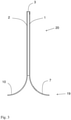
- Fig. 3 shows a barrier 20 which has been formed from a composite material similar to that shown in Fig. 1 and Fig. 2 .
- the lower end 19 of the barrier 20 comprises the first edge region 7 and the second edge region 10.
- the second edge region 10 has the same extension as the first edge region 7.
- the first edge region 7 and the second edge region 10 have been bent outwards from the core layer 3 so that the ends of the first edge region 7 and the second edge region 10 provide a stable support for the barrier 20 when placed on a surface.
- a barrier 20 as shown in Fig. 3 may be used in many different ways. One suitable area of application is to use the barrier 20 in sports using a ball such as indoor soccer.
- the barrier 20 shown in Fig. 3 is very lightweight while at the same time providing sufficient strength for the barrier 20. The low weight ensures easy handling of the barriers 20.
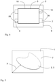
- Fig. 4 shows in a top view a different embodiment of a composite material comprising a first cover sheet 1 and a second cover sheet 2 and a core layer 3 arranged between the first cover sheet 1 and the second cover sheet 2.
- Fig. 5 shows in a top view a different embodiment of a composite material comprising a first cover sheet 1 and a second cover sheet 2 and a core layer 3 arranged between the first cover sheet 1 and the second cover sheet 2.
- the second cover sheet 2 and the core layer 3 have a rectangular shape in Fig. 4 .
- Fig. 6 shows the composite material of Figs. 4 and 5 in a side view.
- the first cover sheet 1 has a larger extension than the core layer 3 and comprises a first edge region 7 free from the core layer 3.
- the first edge region 7 extends from the outer edge 9 of the first cover sheet 1 to the core layer 3 and extends around the entire outer edge 9 of the first cover sheet 1, so that the first edge region 7 encircles the core layer 3.
- the second cover sheet 2 has essentially the same extension as the core layer 3.
- the second cover sheet 2 comprises a narrow second edge region 10 which is free from the core layer 3.
- the second cover sheet extends no more than 5 mm beyond the outer edge of the core layer and preferably no more than 1 mm beyond the outer edge of the core layer, i.e., the third edge region has an extension of no more than 5 mm and preferably no more than 1 mm.
- the second edge region 10 extends around the entire edge of the first cover sheet, so that the second edge region 10 encircles the core layer.
- the extension of the core layer 3 is shown with the dotted line 18 in Fig. 4 .
- the second cover sheet 2 has an irregular shape.
- the shape of the first adhesive layer 4 and thus the shape of the core layer 3 may be achieved by providing the first cover sheet 1 with a mask (not shown) having the shape of the first edge region 7. After having applied the first adhesive layer 4 the mask is removed leaving the first edge region 7 uncovered by adhesive.
- the second cover sheet 2 is shown to have the same extension as the adhesive layer in Fig. 4 .
- the largest extension of the first edge region 7 beyond the edge of the core layer 3 is denoted X in Fig. 5 .
- the extension of the core layer is shown as a rectangle in Fig. 4 . It is, however, possible to provide the core layer shaped as a parallelogram.
- composite material comprises edge regions 28 extending outside the core layer 3 in small areas as is indicated by the dotted regions 28 in Fig. 4 .
- the dotted regions 28 may be sufficient for attachment to a façade of a building (not shown) when the area defined by the core layer 3 defines the area of a façade element to be attached to a facade.
- the extension of the dotted regions 28 beyond the edge of the core layer 3 is denoted X in Fig. 4 .
- Fig. 7 shows a receptacle 21 according to an embodiment of the invention.
- the receptacle 21 has been formed from a composite material 1 as shown in Fig. 4 and Fig. 6 .
- the first edge region 7 has been reformed into a side wall 22 according to anyone of claims 2 to 5, wherein the second cover 2 sheet forms the inner bottom 23 of the receptacle 21 and the first edge region 7 forms the side wall 22 of the receptacle 21.
- the second cover sheet 2 is essentially flat. With the term flat is meant that the variation perpendicular to the surface of the second cover sheet 2 varies no more than 10 % of the largest extension of the second cover sheet 2.
- the form of the wall 22 as shown in Fig. 7 will ensure that sufficient strength is provided through the shape of the wall 22.
- the strength of the inner bottom 23 of the receptacle 21 is provided by the sandwich arrangement of the first cover sheet 1, the second cover sheet 2, and the core layer 3.
- Fig. 8 illustrates schematically a method for applying an adhesive layer 4, 5, on a cover sheet 1, 2.
- the method includes the use of a coating head 24 which operates at a distance Da from the first cover sheet 1 and the second cover sheet 2.
- the coating head 24 comprises a slot 25 through which the adhesive leaves the coating head and through which the adhesive is forced by applying a pressure on the adhesive inside the coating head 24.
- the adhesive can be said to be extruded from the coating head 24 through the slot 25 while moving the cover sheet 1, 2, along the direction 30.
- the adhesive forms a continuous stream from the slot to the cover sheet 1, 2.
- the following steps are wherein the application of the adhesive is ended by the steps of moving the coating head away from the cover sheet a distance D during a time period T, and lowering the pressure P on the adhesive inside the coating head 24.
- the distance D is at least the thickness of the adhesive layer 4, 5 plus at least 5 mm, preferably at least 7 mm, and the time period T is less than 5 seconds, preferably less than 0.5 seconds.
- the pressure P is decreased below ambient pressure. This provides for an abrupt stop in the stream of adhesive.
- the distance Da between the coating head and the cover sheet 1, 2 is typically less than 0.2 mm plus the thickness of the adhesive layer 4, 5.
- the thickness of the adhesive layer 4, 5, is typically 0.15-0,3.
- the adhesive is stored in the reservoir 26.
- the pressure on the adhesive is provided by the pressure means 27.
- the dotted line shows the coating head 24', the reservoir 26', and the pressure means 27' in the position it has when application of adhesive has been terminated.
- Fig. 9 is a flowchart of a method 300 for production of a composite material 100 according to the embodiments of Figs. 1, 2 , 4, 5 and 6 .
- the method comprises the steps of providing 301 a first cover sheet 1 and a second cover sheet 2, applying 302 a first adhesive layer 4 on the first cover sheet 1, applying a second adhesive layer 5 in contact with the second cover sheet 2, applying 303 a flocking material in the form of individual fibres on one of or both adhesive layers, arranging the first cover sheet adjacent to the second cover sheet with the first adhesive layer facing the second adhesive layer and with the fibres in contact with the first adhesive layer as well as the second adhesive layer, and providing 305 for the adhesive layers to cure.
- the first adhesive layer 4 and the second adhesive layer may be applied in many ways.
- the fibres 6 can be of many different materials, such as, e.g., metal or plastic. It is well known in the art how to apply a flocking material in the form of fibres 6 on a surface. The fibres 6 will adhere to the adhesive layer orientated essentially perpendicular to the surface. When the second cover sheet 2 is arranged adjacent to the first cover sheet 1 with the fibres 6 in contact with the first adhesive layer as well as the second adhesive layer 2, only curing of the adhesive layers is required to form the composite material 100. The fibres 6 will only adhere to the adhesive layers 4, 5. Thus, the extension of the core layer will be defined by the adhesive layers. For the illustrated embodiment, both adhesive layers have the same extension. Primarily, it is important to avoid that the first adhesive layer is larger than the second adhesive layer as this would lead to the fibres only be adhered to the first cover sheet in some areas.
- the composite material may of course have other shapes than those that have been shown in the embodiments above.
Landscapes
- Engineering & Computer Science (AREA)
- Mechanical Engineering (AREA)
- Laminated Bodies (AREA)
Claims (12)
- Verbundwerkstoff (100), Folgendes umfassendein erstes Deckblech (1),ein zweites Deckblech (2) undeine Kernschicht (3), die zwischen dem ersten Deckblech (1) und dem zweiten Deckblech (1) angeordnet ist, die Kernschicht (3) Folgendes umfassend:eine erste Klebeschicht (4) im Kontakt mit dem ersten Deckblech (1),eine zweite Klebeschicht (5) im Kontakt mit dem zweiten Deckblech (2) undein Beflockungsmaterial in der Gestalt einzelner Fasern (6), die sich von der ersten Klebeschicht (4) zu der zweiten Klebeschicht (5) ausdehnen,dadurch gekennzeichnet, dass das erste Deckblech (1) eine größere Ausdehnung als die Kernschicht (3) aufweist und mindestens eine erste Randregion (7) umfasst, die von der Kernschicht (3) frei ist,wobei sich die erste Randregion (7) von einem Außenrand (9) des ersten Deckblechs (1) zu der Kernschicht (3) ausdehnt,wobei die Ausdehnung der ersten Randregion (7) mindestens 20 mm über einen Außenrand (18) der Kernschicht (3) hinausgeht undwobei sich das zweite Deckblech (2) nicht mehr als 5 mm über den Außenrand (18) der Kernschicht (3) hinaus ausdehnt.
- Verbundwerkstoff (100) nach Anspruch 1, wobei die Ausdehnung der ersten Randregion (7) über den Außenrand (18) der Kernschicht (3) hinaus mindestens 50 mm ist.
- Verbundwerkstoff (100) nach Anspruch 1 oder 2, wobei sich die erste Randregion (7) um den gesamten Außenrand (9) des ersten Deckblechs (1) herum ausdehnt, so dass die erste Randregion (7) die Kernschicht (3) umschließt.
- Verbundwerkstoff (100) nach Anspruch 1, 2 oder 3, wobei sich das zweite Deckblech (2) nicht mehr als 1 mm über den Außenrand (18) der Kernschicht (3) hinaus ausdehnt.
- Aufnahme (21), die aus einem Verbundwerkstoff (100) nach einem der Ansprüche 1 bis 4 ausgebildet ist, wobei das zweite Deckblech (2) einen Innenboden (23) der Aufnahme (21) ausbildet und mindestens ein Teil der ersten Randregion Seitenwände (24) der Aufnahme (21) ausbildet.
- Verfahren (300) zur Herstellung eines Verbundwerkstoffs (100) nach einem der Ansprüche 1 bis 4, die folgenden Schritte umfassendBereitstellen (301) eines ersten Deckblechs (1) und eines zweiten Deckblechs (2),Aufbringen (302) einer ersten Klebeschicht (4) auf dem ersten Deckblech (1) und einer zweiten Klebeschicht (5) auf dem zweiten Deckblech (2),Aufbringen (303) eines Beflockungsmaterials in der Gestalt einzelner Fasern (6) auf einer der Klebeschichten (4, 5),Anordnen (304) des ersten Deckblechs (1) benachbart zu dem zweiten Deckblech (2), wobei die erste Klebeschicht (4) der zweiten Klebeschicht (5) gegenüber steht und wobei die Fasern (6) mit der ersten Klebeschicht (4) sowie mit der zweiten Klebeschicht (5) im Kontakt sind,Vorsehen (305), dass die Klebeschichten (4, 5) härten, um eine Kernschicht (3) auszubilden, die durch die erste Klebeschicht (4), die zweite Klebeschicht (5) und die Fasern (6) gebildet wird, dadurch gekennzeichnet, dass das erste Deckblech (1) eine größere Ausdehnung als die Kernschicht (3) aufweist und mindestens eine erste Randregion (7) umfasst, die von der Kernschicht (3) frei ist,wobei sich die erste Randregion (7) von einem Außenrand (9) des ersten Deckblechs (1) zu der Kernschicht (3) ausdehnt,wobei die Ausdehnung der ersten Randregion (7) über einen Außenrand (18) der Kernschicht (3) hinaus mindestens 20 mm ist undwobei das zweite Deckblech (2) im Wesentlichen die gleiche Ausdehnung wie die Kernschicht (3) aufweist und sich nicht mehr als 5 mm über den Außenrand (18) der Kernschicht (3) hinaus ausdehnt.
- Verfahren nach Anspruch 6, wobei die Ausdehnung der ersten Randregion (7) über den Außenrand (18) der Kernschicht (3) hinaus mindestens 50 mm ist.
- Verfahren nach Anspruch 6 oder 7, wobei die erste Klebeschicht (4) auf dem ersten Deckblech (1) aufgebracht wird und die zweite Klebeschicht (5) auf dem zweiten Deckblech (2) aufgebracht wird, indem ein Beschichtungskopf (25) verwendet wird, der in einem Abstand von dem ersten Deckblech (1) und dem zweiten Deckblech (2) arbeitet.
- Verfahren nach Anspruch 6, 7 oder 8, wobei der Beschichtungskopf (25) einen Schlitz (26) umfasst, durch den der Klebstoff den Beschichtungskopf (25) verlässt und durch den der Klebstoff durch Anwenden eines Drucks auf den Klebstoff in dem Beschichtungskopf (25) gedrückt wird.
- Verfahren nach Anspruch 9, wobei das Aufbringen des Klebstoffs auf den jeweiligen Deckblechen (1, 2) durch die folgenden Schritte beendet wirdWegbewegen des Beschichtungskopfs (25) von dem jeweiligen Deckblech (1, 2) undAbsenken des Drucks auf den Klebstoff in dem Beschichtungskopf (25).
- Verfahren nach Anspruch 10, wobei der Beschichtungskopf (25) um mindestens 5 mm von dem jeweiligen Deckblech (1, 2) mit einer Geschwindigkeit von mindestens 200 mm pro Minute wegbewegt wird.
- Verfahren nach Anspruch 10 oder 11, wobei der Druck auf den Klebstoff in dem Beschichtungskopf (25) unter den Umgebungsdruck vermindert wird.
Priority Applications (1)
| Application Number | Priority Date | Filing Date | Title |
|---|---|---|---|
| PL18714630T PL3595891T3 (pl) | 2017-03-17 | 2018-03-16 | Materiał kompozytowy oraz sposób jego wytwarzania |
Applications Claiming Priority (2)
| Application Number | Priority Date | Filing Date | Title |
|---|---|---|---|
| SE1750323A SE541379C2 (en) | 2017-03-17 | 2017-03-17 | Composite material and method for production of the same |
| PCT/SE2018/050263 WO2018169482A1 (en) | 2017-03-17 | 2018-03-16 | Composite material and method for production of the same |
Publications (2)
| Publication Number | Publication Date |
|---|---|
| EP3595891A1 EP3595891A1 (de) | 2020-01-22 |
| EP3595891B1 true EP3595891B1 (de) | 2022-02-16 |
Family
ID=61832565
Family Applications (1)
| Application Number | Title | Priority Date | Filing Date |
|---|---|---|---|
| EP18714630.3A Active EP3595891B1 (de) | 2017-03-17 | 2018-03-16 | Verbundwerkstoff und verfahren zur herstellung davon |
Country Status (8)
| Country | Link |
|---|---|
| US (1) | US11312101B2 (de) |
| EP (1) | EP3595891B1 (de) |
| CN (1) | CN110709236A (de) |
| DK (1) | DK3595891T3 (de) |
| ES (1) | ES2913748T3 (de) |
| PL (1) | PL3595891T3 (de) |
| SE (1) | SE541379C2 (de) |
| WO (1) | WO2018169482A1 (de) |
Families Citing this family (1)
| Publication number | Priority date | Publication date | Assignee | Title |
|---|---|---|---|---|
| JP7484828B2 (ja) * | 2021-06-25 | 2024-05-16 | トヨタ自動車株式会社 | 見切り線の形成方法 |
Family Cites Families (13)
| Publication number | Priority date | Publication date | Assignee | Title |
|---|---|---|---|---|
| US2276374A (en) * | 1939-07-14 | 1942-03-17 | Derman Harry | Collapsible drawer |
| SE465260B (sv) | 1988-03-16 | 1991-08-19 | Scanalma Ab | Sandwichkonstruktion och foerfarande foer framstaellning av denna |
| SE506929C2 (sv) * | 1996-07-04 | 1998-03-02 | Volvo Ab | Konstruktionsmaterial i fordon bestående av formbart, metalliskt sandwichelement |
| WO2001076864A2 (en) | 2000-04-07 | 2001-10-18 | Dofasco Inc. | Multi-dimensional tailored laminate |
| DE10214010A1 (de) * | 2002-03-29 | 2003-10-16 | Hssa Sweden Ab Trollhaettan | Vorrichtung und Verfahren zur Herstellung von Verbundwerkstoffen |
| SE0301319L (sv) * | 2003-05-07 | 2004-11-08 | Hssa Sweden Ab | Metod för tillverkning av kompositstrukturer |
| SE0301337D0 (sv) * | 2003-05-07 | 2003-05-07 | Hssa Sweden Ab | Deformable elements from composite structures |
| CN201196336Y (zh) * | 2008-03-25 | 2009-02-18 | 王贞禄 | 车体用板材结构 |
| DE102012103332A1 (de) | 2012-04-17 | 2013-10-17 | Thyssenkrupp Steel Europe Ag | Verfahren zum Herstellen großer Leichtbleche |
| CN202850286U (zh) * | 2012-10-25 | 2013-04-03 | 成都市第六建筑工程公司 | 一种自保温搪瓷钢板 |
| DE102014116112A1 (de) * | 2014-11-05 | 2016-05-12 | Dr. Ing. H.C. F. Porsche Aktiengesellschaft | Verkleidungsteil |
| US10647082B2 (en) | 2015-03-19 | 2020-05-12 | Lg Hausys, Ltd. | Sandwich panel and method for manufacturing same |
| SG10201505238XA (en) * | 2015-07-01 | 2017-02-27 | Xpac Technologies Pte Ltd | A container assembly |
-
2017
- 2017-03-17 SE SE1750323A patent/SE541379C2/en unknown
-
2018
- 2018-03-16 US US16/494,444 patent/US11312101B2/en active Active
- 2018-03-16 EP EP18714630.3A patent/EP3595891B1/de active Active
- 2018-03-16 CN CN201880018911.3A patent/CN110709236A/zh active Pending
- 2018-03-16 ES ES18714630T patent/ES2913748T3/es active Active
- 2018-03-16 DK DK18714630.3T patent/DK3595891T3/da active
- 2018-03-16 PL PL18714630T patent/PL3595891T3/pl unknown
- 2018-03-16 WO PCT/SE2018/050263 patent/WO2018169482A1/en not_active Ceased
Non-Patent Citations (1)
| Title |
|---|
| None * |
Also Published As
| Publication number | Publication date |
|---|---|
| PL3595891T3 (pl) | 2022-07-11 |
| ES2913748T3 (es) | 2022-06-06 |
| DK3595891T3 (da) | 2022-05-23 |
| US11312101B2 (en) | 2022-04-26 |
| SE1750323A1 (sv) | 2018-09-18 |
| SE541379C2 (en) | 2019-09-10 |
| US20200086607A1 (en) | 2020-03-19 |
| CN110709236A (zh) | 2020-01-17 |
| EP3595891A1 (de) | 2020-01-22 |
| WO2018169482A1 (en) | 2018-09-20 |
Similar Documents
| Publication | Publication Date | Title |
|---|---|---|
| JP2017519663A (ja) | ハニカムコア構造 | |
| US4136630A (en) | Sail batten | |
| AU2013212684A1 (en) | Composite corner bead | |
| JP4504005B2 (ja) | 突合せ溶接された金属層のラミネート | |
| EP3595891B1 (de) | Verbundwerkstoff und verfahren zur herstellung davon | |
| US8857565B2 (en) | Method for making acoustical panels with a three-dimensional surface | |
| KR100847763B1 (ko) | 조립식 물탱크용 패널 및 그 제조방법 | |
| KR102236303B1 (ko) | 외장패널용 금속복합패널 성형장치와 이를 이용한 성형방법 | |
| US7771813B2 (en) | Sandwich panel core | |
| JP4121911B2 (ja) | 格子部材およびそれを用いた耐震壁用ブロック | |
| WO2007053505A3 (en) | Extruded laminated floor mat and method of manufacturing same | |
| DE102011011079A1 (de) | Fußbodenleiste sowie Verfahren zur Herstellung einer Fußbodenleiste | |
| US20070273967A1 (en) | Visual Communication Panel And Method For Manufacturing It | |
| EP1704041B1 (de) | Vorrichtung und verfahren zur herstellung eines formteils | |
| JPH01214432A (ja) | ドア板要素 | |
| KR100666845B1 (ko) | 디프 드로잉 가공 심재 및 그것을 이용한 샌드위치 패널 | |
| US20050224164A1 (en) | Method for making a composite board and the composite board made thereby | |
| JP6543093B2 (ja) | パネルの製造方法 | |
| KR100493690B1 (ko) | 중질섬유판을 구비하는 도어 | |
| EP2855142A1 (de) | Bauplatte | |
| AU2004319030A1 (en) | Process for manufacturing insulating panels with polimeric foam and mineral wool | |
| WO2021122174A1 (en) | Metal reinforced board | |
| DE8910066U1 (de) | Flächiger Formkörper | |
| JP2012115993A (ja) | 加飾成形品 | |
| JPH03180662A (ja) | コーナ用複合パネル |
Legal Events
| Date | Code | Title | Description |
|---|---|---|---|
| STAA | Information on the status of an ep patent application or granted ep patent |
Free format text: STATUS: UNKNOWN |
|
| STAA | Information on the status of an ep patent application or granted ep patent |
Free format text: STATUS: THE INTERNATIONAL PUBLICATION HAS BEEN MADE |
|
| PUAI | Public reference made under article 153(3) epc to a published international application that has entered the european phase |
Free format text: ORIGINAL CODE: 0009012 |
|
| STAA | Information on the status of an ep patent application or granted ep patent |
Free format text: STATUS: REQUEST FOR EXAMINATION WAS MADE |
|
| 17P | Request for examination filed |
Effective date: 20190911 |
|
| AK | Designated contracting states |
Kind code of ref document: A1 Designated state(s): AL AT BE BG CH CY CZ DE DK EE ES FI FR GB GR HR HU IE IS IT LI LT LU LV MC MK MT NL NO PL PT RO RS SE SI SK SM TR |
|
| AX | Request for extension of the european patent |
Extension state: BA ME |
|
| DAV | Request for validation of the european patent (deleted) | ||
| DAX | Request for extension of the european patent (deleted) | ||
| GRAP | Despatch of communication of intention to grant a patent |
Free format text: ORIGINAL CODE: EPIDOSNIGR1 |
|
| STAA | Information on the status of an ep patent application or granted ep patent |
Free format text: STATUS: GRANT OF PATENT IS INTENDED |
|
| INTG | Intention to grant announced |
Effective date: 20210323 |
|
| GRAJ | Information related to disapproval of communication of intention to grant by the applicant or resumption of examination proceedings by the epo deleted |
Free format text: ORIGINAL CODE: EPIDOSDIGR1 |
|
| STAA | Information on the status of an ep patent application or granted ep patent |
Free format text: STATUS: REQUEST FOR EXAMINATION WAS MADE |
|
| INTC | Intention to grant announced (deleted) | ||
| GRAP | Despatch of communication of intention to grant a patent |
Free format text: ORIGINAL CODE: EPIDOSNIGR1 |
|
| STAA | Information on the status of an ep patent application or granted ep patent |
Free format text: STATUS: GRANT OF PATENT IS INTENDED |
|
| INTG | Intention to grant announced |
Effective date: 20210928 |
|
| GRAS | Grant fee paid |
Free format text: ORIGINAL CODE: EPIDOSNIGR3 |
|
| GRAA | (expected) grant |
Free format text: ORIGINAL CODE: 0009210 |
|
| STAA | Information on the status of an ep patent application or granted ep patent |
Free format text: STATUS: THE PATENT HAS BEEN GRANTED |
|
| AK | Designated contracting states |
Kind code of ref document: B1 Designated state(s): AL AT BE BG CH CY CZ DE DK EE ES FI FR GB GR HR HU IE IS IT LI LT LU LV MC MK MT NL NO PL PT RO RS SE SI SK SM TR |
|
| REG | Reference to a national code |
Ref country code: GB Ref legal event code: FG4D |
|
| REG | Reference to a national code |
Ref country code: CH Ref legal event code: EP |
|
| REG | Reference to a national code |
Ref country code: DE Ref legal event code: R096 Ref document number: 602018030885 Country of ref document: DE |
|
| REG | Reference to a national code |
Ref country code: AT Ref legal event code: REF Ref document number: 1468647 Country of ref document: AT Kind code of ref document: T Effective date: 20220315 |
|
| REG | Reference to a national code |
Ref country code: IE Ref legal event code: FG4D |
|
| REG | Reference to a national code |
Ref country code: FI Ref legal event code: FGE |
|
| REG | Reference to a national code |
Ref country code: DK Ref legal event code: T3 Effective date: 20220518 |
|
| REG | Reference to a national code |
Ref country code: SE Ref legal event code: TRGR |
|
| REG | Reference to a national code |
Ref country code: ES Ref legal event code: FG2A Ref document number: 2913748 Country of ref document: ES Kind code of ref document: T3 Effective date: 20220606 |
|
| REG | Reference to a national code |
Ref country code: NO Ref legal event code: T2 Effective date: 20220216 |
|
| REG | Reference to a national code |
Ref country code: LT Ref legal event code: MG9D |
|
| REG | Reference to a national code |
Ref country code: NL Ref legal event code: MP Effective date: 20220216 |
|
| REG | Reference to a national code |
Ref country code: AT Ref legal event code: MK05 Ref document number: 1468647 Country of ref document: AT Kind code of ref document: T Effective date: 20220216 |
|
| PG25 | Lapsed in a contracting state [announced via postgrant information from national office to epo] |
Ref country code: RS Free format text: LAPSE BECAUSE OF FAILURE TO SUBMIT A TRANSLATION OF THE DESCRIPTION OR TO PAY THE FEE WITHIN THE PRESCRIBED TIME-LIMIT Effective date: 20220216 Ref country code: PT Free format text: LAPSE BECAUSE OF FAILURE TO SUBMIT A TRANSLATION OF THE DESCRIPTION OR TO PAY THE FEE WITHIN THE PRESCRIBED TIME-LIMIT Effective date: 20220616 Ref country code: NL Free format text: LAPSE BECAUSE OF FAILURE TO SUBMIT A TRANSLATION OF THE DESCRIPTION OR TO PAY THE FEE WITHIN THE PRESCRIBED TIME-LIMIT Effective date: 20220216 Ref country code: LT Free format text: LAPSE BECAUSE OF FAILURE TO SUBMIT A TRANSLATION OF THE DESCRIPTION OR TO PAY THE FEE WITHIN THE PRESCRIBED TIME-LIMIT Effective date: 20220216 Ref country code: HR Free format text: LAPSE BECAUSE OF FAILURE TO SUBMIT A TRANSLATION OF THE DESCRIPTION OR TO PAY THE FEE WITHIN THE PRESCRIBED TIME-LIMIT Effective date: 20220216 Ref country code: BG Free format text: LAPSE BECAUSE OF FAILURE TO SUBMIT A TRANSLATION OF THE DESCRIPTION OR TO PAY THE FEE WITHIN THE PRESCRIBED TIME-LIMIT Effective date: 20220516 |
|
| PG25 | Lapsed in a contracting state [announced via postgrant information from national office to epo] |
Ref country code: LV Free format text: LAPSE BECAUSE OF FAILURE TO SUBMIT A TRANSLATION OF THE DESCRIPTION OR TO PAY THE FEE WITHIN THE PRESCRIBED TIME-LIMIT Effective date: 20220216 Ref country code: GR Free format text: LAPSE BECAUSE OF FAILURE TO SUBMIT A TRANSLATION OF THE DESCRIPTION OR TO PAY THE FEE WITHIN THE PRESCRIBED TIME-LIMIT Effective date: 20220517 Ref country code: AT Free format text: LAPSE BECAUSE OF FAILURE TO SUBMIT A TRANSLATION OF THE DESCRIPTION OR TO PAY THE FEE WITHIN THE PRESCRIBED TIME-LIMIT Effective date: 20220216 |
|
| PG25 | Lapsed in a contracting state [announced via postgrant information from national office to epo] |
Ref country code: IS Free format text: LAPSE BECAUSE OF FAILURE TO SUBMIT A TRANSLATION OF THE DESCRIPTION OR TO PAY THE FEE WITHIN THE PRESCRIBED TIME-LIMIT Effective date: 20220617 |
|
| PG25 | Lapsed in a contracting state [announced via postgrant information from national office to epo] |
Ref country code: SM Free format text: LAPSE BECAUSE OF FAILURE TO SUBMIT A TRANSLATION OF THE DESCRIPTION OR TO PAY THE FEE WITHIN THE PRESCRIBED TIME-LIMIT Effective date: 20220216 Ref country code: SK Free format text: LAPSE BECAUSE OF FAILURE TO SUBMIT A TRANSLATION OF THE DESCRIPTION OR TO PAY THE FEE WITHIN THE PRESCRIBED TIME-LIMIT Effective date: 20220216 Ref country code: RO Free format text: LAPSE BECAUSE OF FAILURE TO SUBMIT A TRANSLATION OF THE DESCRIPTION OR TO PAY THE FEE WITHIN THE PRESCRIBED TIME-LIMIT Effective date: 20220216 Ref country code: EE Free format text: LAPSE BECAUSE OF FAILURE TO SUBMIT A TRANSLATION OF THE DESCRIPTION OR TO PAY THE FEE WITHIN THE PRESCRIBED TIME-LIMIT Effective date: 20220216 Ref country code: CZ Free format text: LAPSE BECAUSE OF FAILURE TO SUBMIT A TRANSLATION OF THE DESCRIPTION OR TO PAY THE FEE WITHIN THE PRESCRIBED TIME-LIMIT Effective date: 20220216 |
|
| REG | Reference to a national code |
Ref country code: CH Ref legal event code: PL |
|
| REG | Reference to a national code |
Ref country code: DE Ref legal event code: R097 Ref document number: 602018030885 Country of ref document: DE |
|
| PG25 | Lapsed in a contracting state [announced via postgrant information from national office to epo] |
Ref country code: MC Free format text: LAPSE BECAUSE OF FAILURE TO SUBMIT A TRANSLATION OF THE DESCRIPTION OR TO PAY THE FEE WITHIN THE PRESCRIBED TIME-LIMIT Effective date: 20220216 Ref country code: AL Free format text: LAPSE BECAUSE OF FAILURE TO SUBMIT A TRANSLATION OF THE DESCRIPTION OR TO PAY THE FEE WITHIN THE PRESCRIBED TIME-LIMIT Effective date: 20220216 |
|
| REG | Reference to a national code |
Ref country code: BE Ref legal event code: MM Effective date: 20220331 |
|
| PLBE | No opposition filed within time limit |
Free format text: ORIGINAL CODE: 0009261 |
|
| STAA | Information on the status of an ep patent application or granted ep patent |
Free format text: STATUS: NO OPPOSITION FILED WITHIN TIME LIMIT |
|
| 26N | No opposition filed |
Effective date: 20221117 |
|
| PG25 | Lapsed in a contracting state [announced via postgrant information from national office to epo] |
Ref country code: LU Free format text: LAPSE BECAUSE OF NON-PAYMENT OF DUE FEES Effective date: 20220316 Ref country code: LI Free format text: LAPSE BECAUSE OF NON-PAYMENT OF DUE FEES Effective date: 20220331 Ref country code: IE Free format text: LAPSE BECAUSE OF NON-PAYMENT OF DUE FEES Effective date: 20220316 Ref country code: CH Free format text: LAPSE BECAUSE OF NON-PAYMENT OF DUE FEES Effective date: 20220331 |
|
| PG25 | Lapsed in a contracting state [announced via postgrant information from national office to epo] |
Ref country code: SI Free format text: LAPSE BECAUSE OF FAILURE TO SUBMIT A TRANSLATION OF THE DESCRIPTION OR TO PAY THE FEE WITHIN THE PRESCRIBED TIME-LIMIT Effective date: 20220216 Ref country code: BE Free format text: LAPSE BECAUSE OF NON-PAYMENT OF DUE FEES Effective date: 20220331 |
|
| PG25 | Lapsed in a contracting state [announced via postgrant information from national office to epo] |
Ref country code: IT Free format text: LAPSE BECAUSE OF FAILURE TO SUBMIT A TRANSLATION OF THE DESCRIPTION OR TO PAY THE FEE WITHIN THE PRESCRIBED TIME-LIMIT Effective date: 20220216 |
|
| PG25 | Lapsed in a contracting state [announced via postgrant information from national office to epo] |
Ref country code: MK Free format text: LAPSE BECAUSE OF FAILURE TO SUBMIT A TRANSLATION OF THE DESCRIPTION OR TO PAY THE FEE WITHIN THE PRESCRIBED TIME-LIMIT Effective date: 20220216 Ref country code: CY Free format text: LAPSE BECAUSE OF FAILURE TO SUBMIT A TRANSLATION OF THE DESCRIPTION OR TO PAY THE FEE WITHIN THE PRESCRIBED TIME-LIMIT Effective date: 20220216 |
|
| PGFP | Annual fee paid to national office [announced via postgrant information from national office to epo] |
Ref country code: FI Payment date: 20240319 Year of fee payment: 7 Ref country code: DE Payment date: 20240319 Year of fee payment: 7 Ref country code: GB Payment date: 20240318 Year of fee payment: 7 |
|
| PG25 | Lapsed in a contracting state [announced via postgrant information from national office to epo] |
Ref country code: HU Free format text: LAPSE BECAUSE OF FAILURE TO SUBMIT A TRANSLATION OF THE DESCRIPTION OR TO PAY THE FEE WITHIN THE PRESCRIBED TIME-LIMIT; INVALID AB INITIO Effective date: 20180316 |
|
| PGFP | Annual fee paid to national office [announced via postgrant information from national office to epo] |
Ref country code: SE Payment date: 20240319 Year of fee payment: 7 Ref country code: FR Payment date: 20240315 Year of fee payment: 7 Ref country code: DK Payment date: 20240320 Year of fee payment: 7 Ref country code: PL Payment date: 20240227 Year of fee payment: 7 |
|
| PGFP | Annual fee paid to national office [announced via postgrant information from national office to epo] |
Ref country code: ES Payment date: 20240412 Year of fee payment: 7 |
|
| PGFP | Annual fee paid to national office [announced via postgrant information from national office to epo] |
Ref country code: NO Payment date: 20240322 Year of fee payment: 7 |
|
| PG25 | Lapsed in a contracting state [announced via postgrant information from national office to epo] |
Ref country code: MT Free format text: LAPSE BECAUSE OF FAILURE TO SUBMIT A TRANSLATION OF THE DESCRIPTION OR TO PAY THE FEE WITHIN THE PRESCRIBED TIME-LIMIT Effective date: 20220216 |
|
| REG | Reference to a national code |
Ref country code: DE Ref legal event code: R119 Ref document number: 602018030885 Country of ref document: DE |
|
| PG25 | Lapsed in a contracting state [announced via postgrant information from national office to epo] |
Ref country code: FI Free format text: LAPSE BECAUSE OF NON-PAYMENT OF DUE FEES Effective date: 20250316 |
|
| REG | Reference to a national code |
Ref country code: DK Ref legal event code: EBP Effective date: 20250331 |
|
| REG | Reference to a national code |
Ref country code: SE Ref legal event code: EUG |
|
| GBPC | Gb: european patent ceased through non-payment of renewal fee |
Effective date: 20250316 |
|
| PG25 | Lapsed in a contracting state [announced via postgrant information from national office to epo] |
Ref country code: TR Free format text: LAPSE BECAUSE OF FAILURE TO SUBMIT A TRANSLATION OF THE DESCRIPTION OR TO PAY THE FEE WITHIN THE PRESCRIBED TIME-LIMIT Effective date: 20220216 |
|
| PG25 | Lapsed in a contracting state [announced via postgrant information from national office to epo] |
Ref country code: DE Free format text: LAPSE BECAUSE OF NON-PAYMENT OF DUE FEES Effective date: 20251001 |
|
| PG25 | Lapsed in a contracting state [announced via postgrant information from national office to epo] |
Ref country code: GB Free format text: LAPSE BECAUSE OF NON-PAYMENT OF DUE FEES Effective date: 20250316 |
|
| PG25 | Lapsed in a contracting state [announced via postgrant information from national office to epo] |
Ref country code: NO Free format text: LAPSE BECAUSE OF NON-PAYMENT OF DUE FEES Effective date: 20250331 |
|
| PG25 | Lapsed in a contracting state [announced via postgrant information from national office to epo] |
Ref country code: FR Free format text: LAPSE BECAUSE OF NON-PAYMENT OF DUE FEES Effective date: 20250331 |
|
| PG25 | Lapsed in a contracting state [announced via postgrant information from national office to epo] |
Ref country code: SE Free format text: LAPSE BECAUSE OF NON-PAYMENT OF DUE FEES Effective date: 20250317 |