EP3595891B1 - Composite material and method for production of the same - Google Patents
Composite material and method for production of the same Download PDFInfo
- Publication number
- EP3595891B1 EP3595891B1 EP18714630.3A EP18714630A EP3595891B1 EP 3595891 B1 EP3595891 B1 EP 3595891B1 EP 18714630 A EP18714630 A EP 18714630A EP 3595891 B1 EP3595891 B1 EP 3595891B1
- Authority
- EP
- European Patent Office
- Prior art keywords
- cover sheet
- core layer
- adhesive
- edge region
- adhesive layer
- Prior art date
- Legal status (The legal status is an assumption and is not a legal conclusion. Google has not performed a legal analysis and makes no representation as to the accuracy of the status listed.)
- Active
Links
- 239000002131 composite material Substances 0.000 title claims description 67
- 238000004519 manufacturing process Methods 0.000 title claims description 14
- 239000012792 core layer Substances 0.000 claims description 103
- 239000012790 adhesive layer Substances 0.000 claims description 76
- 239000000853 adhesive Substances 0.000 claims description 40
- 230000001070 adhesive effect Effects 0.000 claims description 40
- 239000011248 coating agent Substances 0.000 claims description 34
- 238000000576 coating method Methods 0.000 claims description 34
- 238000000034 method Methods 0.000 claims description 24
- 239000000463 material Substances 0.000 claims description 20
- 230000003247 decreasing effect Effects 0.000 claims description 5
- 239000000835 fiber Substances 0.000 claims description 2
- 230000004888 barrier function Effects 0.000 description 11
- 239000002184 metal Substances 0.000 description 7
- 239000000047 product Substances 0.000 description 4
- 239000010410 layer Substances 0.000 description 3
- 239000004677 Nylon Substances 0.000 description 2
- 238000005452 bending Methods 0.000 description 2
- 238000010276 construction Methods 0.000 description 2
- 229920001778 nylon Polymers 0.000 description 2
- 239000004033 plastic Substances 0.000 description 2
- 229920000914 Metallic fiber Polymers 0.000 description 1
- 229910000831 Steel Inorganic materials 0.000 description 1
- 238000010521 absorption reaction Methods 0.000 description 1
- 239000004020 conductor Substances 0.000 description 1
- 239000011162 core material Substances 0.000 description 1
- 230000001419 dependent effect Effects 0.000 description 1
- -1 e.g. Substances 0.000 description 1
- 238000004924 electrostatic deposition Methods 0.000 description 1
- 239000012467 final product Substances 0.000 description 1
- 238000009957 hemming Methods 0.000 description 1
- 230000001788 irregular Effects 0.000 description 1
- 239000003562 lightweight material Substances 0.000 description 1
- 238000003825 pressing Methods 0.000 description 1
- 239000011343 solid material Substances 0.000 description 1
- 239000010959 steel Substances 0.000 description 1
Images


Classifications
-
- B—PERFORMING OPERATIONS; TRANSPORTING
- B32—LAYERED PRODUCTS
- B32B—LAYERED PRODUCTS, i.e. PRODUCTS BUILT-UP OF STRATA OF FLAT OR NON-FLAT, e.g. CELLULAR OR HONEYCOMB, FORM
- B32B5/00—Layered products characterised by the non- homogeneity or physical structure, i.e. comprising a fibrous, filamentary, particulate or foam layer; Layered products characterised by having a layer differing constitutionally or physically in different parts
- B32B5/02—Layered products characterised by the non- homogeneity or physical structure, i.e. comprising a fibrous, filamentary, particulate or foam layer; Layered products characterised by having a layer differing constitutionally or physically in different parts characterised by structural features of a fibrous or filamentary layer
-
- B—PERFORMING OPERATIONS; TRANSPORTING
- B32—LAYERED PRODUCTS
- B32B—LAYERED PRODUCTS, i.e. PRODUCTS BUILT-UP OF STRATA OF FLAT OR NON-FLAT, e.g. CELLULAR OR HONEYCOMB, FORM
- B32B15/00—Layered products comprising a layer of metal
- B32B15/14—Layered products comprising a layer of metal next to a fibrous or filamentary layer
-
- B—PERFORMING OPERATIONS; TRANSPORTING
- B05—SPRAYING OR ATOMISING IN GENERAL; APPLYING FLUENT MATERIALS TO SURFACES, IN GENERAL
- B05D—PROCESSES FOR APPLYING FLUENT MATERIALS TO SURFACES, IN GENERAL
- B05D1/00—Processes for applying liquids or other fluent materials
- B05D1/02—Processes for applying liquids or other fluent materials performed by spraying
- B05D1/12—Applying particulate materials
- B05D1/14—Flocking
-
- B—PERFORMING OPERATIONS; TRANSPORTING
- B05—SPRAYING OR ATOMISING IN GENERAL; APPLYING FLUENT MATERIALS TO SURFACES, IN GENERAL
- B05D—PROCESSES FOR APPLYING FLUENT MATERIALS TO SURFACES, IN GENERAL
- B05D1/00—Processes for applying liquids or other fluent materials
- B05D1/16—Flocking otherwise than by spraying
-
- B—PERFORMING OPERATIONS; TRANSPORTING
- B32—LAYERED PRODUCTS
- B32B—LAYERED PRODUCTS, i.e. PRODUCTS BUILT-UP OF STRATA OF FLAT OR NON-FLAT, e.g. CELLULAR OR HONEYCOMB, FORM
- B32B1/00—Layered products having a general shape other than plane
-
- B—PERFORMING OPERATIONS; TRANSPORTING
- B32—LAYERED PRODUCTS
- B32B—LAYERED PRODUCTS, i.e. PRODUCTS BUILT-UP OF STRATA OF FLAT OR NON-FLAT, e.g. CELLULAR OR HONEYCOMB, FORM
- B32B15/00—Layered products comprising a layer of metal
-
- B—PERFORMING OPERATIONS; TRANSPORTING
- B32—LAYERED PRODUCTS
- B32B—LAYERED PRODUCTS, i.e. PRODUCTS BUILT-UP OF STRATA OF FLAT OR NON-FLAT, e.g. CELLULAR OR HONEYCOMB, FORM
- B32B15/00—Layered products comprising a layer of metal
- B32B15/04—Layered products comprising a layer of metal comprising metal as the main or only constituent of a layer, which is next to another layer of the same or of a different material
- B32B15/043—Layered products comprising a layer of metal comprising metal as the main or only constituent of a layer, which is next to another layer of the same or of a different material of metal
-
- B—PERFORMING OPERATIONS; TRANSPORTING
- B32—LAYERED PRODUCTS
- B32B—LAYERED PRODUCTS, i.e. PRODUCTS BUILT-UP OF STRATA OF FLAT OR NON-FLAT, e.g. CELLULAR OR HONEYCOMB, FORM
- B32B3/00—Layered products comprising a layer with external or internal discontinuities or unevennesses, or a layer of non-planar form; Layered products having particular features of form
- B32B3/02—Layered products comprising a layer with external or internal discontinuities or unevennesses, or a layer of non-planar form; Layered products having particular features of form characterised by features of form at particular places, e.g. in edge regions
-
- B—PERFORMING OPERATIONS; TRANSPORTING
- B32—LAYERED PRODUCTS
- B32B—LAYERED PRODUCTS, i.e. PRODUCTS BUILT-UP OF STRATA OF FLAT OR NON-FLAT, e.g. CELLULAR OR HONEYCOMB, FORM
- B32B37/00—Methods or apparatus for laminating, e.g. by curing or by ultrasonic bonding
- B32B37/12—Methods or apparatus for laminating, e.g. by curing or by ultrasonic bonding characterised by using adhesives
- B32B37/1284—Application of adhesive
-
- B—PERFORMING OPERATIONS; TRANSPORTING
- B32—LAYERED PRODUCTS
- B32B—LAYERED PRODUCTS, i.e. PRODUCTS BUILT-UP OF STRATA OF FLAT OR NON-FLAT, e.g. CELLULAR OR HONEYCOMB, FORM
- B32B37/00—Methods or apparatus for laminating, e.g. by curing or by ultrasonic bonding
- B32B37/14—Methods or apparatus for laminating, e.g. by curing or by ultrasonic bonding characterised by the properties of the layers
- B32B37/24—Methods or apparatus for laminating, e.g. by curing or by ultrasonic bonding characterised by the properties of the layers with at least one layer not being coherent before laminating, e.g. made up from granular material sprinkled onto a substrate
-
- B—PERFORMING OPERATIONS; TRANSPORTING
- B32—LAYERED PRODUCTS
- B32B—LAYERED PRODUCTS, i.e. PRODUCTS BUILT-UP OF STRATA OF FLAT OR NON-FLAT, e.g. CELLULAR OR HONEYCOMB, FORM
- B32B5/00—Layered products characterised by the non- homogeneity or physical structure, i.e. comprising a fibrous, filamentary, particulate or foam layer; Layered products characterised by having a layer differing constitutionally or physically in different parts
- B32B5/02—Layered products characterised by the non- homogeneity or physical structure, i.e. comprising a fibrous, filamentary, particulate or foam layer; Layered products characterised by having a layer differing constitutionally or physically in different parts characterised by structural features of a fibrous or filamentary layer
- B32B5/06—Layered products characterised by the non- homogeneity or physical structure, i.e. comprising a fibrous, filamentary, particulate or foam layer; Layered products characterised by having a layer differing constitutionally or physically in different parts characterised by structural features of a fibrous or filamentary layer characterised by a fibrous or filamentary layer mechanically connected, e.g. by needling to another layer, e.g. of fibres, of paper
-
- B—PERFORMING OPERATIONS; TRANSPORTING
- B32—LAYERED PRODUCTS
- B32B—LAYERED PRODUCTS, i.e. PRODUCTS BUILT-UP OF STRATA OF FLAT OR NON-FLAT, e.g. CELLULAR OR HONEYCOMB, FORM
- B32B7/00—Layered products characterised by the relation between layers; Layered products characterised by the relative orientation of features between layers, or by the relative values of a measurable parameter between layers, i.e. products comprising layers having different physical, chemical or physicochemical properties; Layered products characterised by the interconnection of layers
- B32B7/04—Interconnection of layers
- B32B7/05—Interconnection of layers the layers not being connected over the whole surface, e.g. discontinuous connection or patterned connection
-
- B—PERFORMING OPERATIONS; TRANSPORTING
- B32—LAYERED PRODUCTS
- B32B—LAYERED PRODUCTS, i.e. PRODUCTS BUILT-UP OF STRATA OF FLAT OR NON-FLAT, e.g. CELLULAR OR HONEYCOMB, FORM
- B32B7/00—Layered products characterised by the relation between layers; Layered products characterised by the relative orientation of features between layers, or by the relative values of a measurable parameter between layers, i.e. products comprising layers having different physical, chemical or physicochemical properties; Layered products characterised by the interconnection of layers
- B32B7/04—Interconnection of layers
- B32B7/12—Interconnection of layers using interposed adhesives or interposed materials with bonding properties
-
- B—PERFORMING OPERATIONS; TRANSPORTING
- B65—CONVEYING; PACKING; STORING; HANDLING THIN OR FILAMENTARY MATERIAL
- B65D—CONTAINERS FOR STORAGE OR TRANSPORT OF ARTICLES OR MATERIALS, e.g. BAGS, BARRELS, BOTTLES, BOXES, CANS, CARTONS, CRATES, DRUMS, JARS, TANKS, HOPPERS, FORWARDING CONTAINERS; ACCESSORIES, CLOSURES, OR FITTINGS THEREFOR; PACKAGING ELEMENTS; PACKAGES
- B65D65/00—Wrappers or flexible covers; Packaging materials of special type or form
- B65D65/38—Packaging materials of special type or form
- B65D65/40—Applications of laminates for particular packaging purposes
-
- B—PERFORMING OPERATIONS; TRANSPORTING
- B32—LAYERED PRODUCTS
- B32B—LAYERED PRODUCTS, i.e. PRODUCTS BUILT-UP OF STRATA OF FLAT OR NON-FLAT, e.g. CELLULAR OR HONEYCOMB, FORM
- B32B37/00—Methods or apparatus for laminating, e.g. by curing or by ultrasonic bonding
- B32B37/14—Methods or apparatus for laminating, e.g. by curing or by ultrasonic bonding characterised by the properties of the layers
- B32B37/24—Methods or apparatus for laminating, e.g. by curing or by ultrasonic bonding characterised by the properties of the layers with at least one layer not being coherent before laminating, e.g. made up from granular material sprinkled onto a substrate
- B32B2037/243—Coating
-
- B—PERFORMING OPERATIONS; TRANSPORTING
- B32—LAYERED PRODUCTS
- B32B—LAYERED PRODUCTS, i.e. PRODUCTS BUILT-UP OF STRATA OF FLAT OR NON-FLAT, e.g. CELLULAR OR HONEYCOMB, FORM
- B32B2250/00—Layers arrangement
- B32B2250/02—2 layers
-
- B—PERFORMING OPERATIONS; TRANSPORTING
- B32—LAYERED PRODUCTS
- B32B—LAYERED PRODUCTS, i.e. PRODUCTS BUILT-UP OF STRATA OF FLAT OR NON-FLAT, e.g. CELLULAR OR HONEYCOMB, FORM
- B32B2250/00—Layers arrangement
- B32B2250/40—Symmetrical or sandwich layers, e.g. ABA, ABCBA, ABCCBA
-
- B—PERFORMING OPERATIONS; TRANSPORTING
- B32—LAYERED PRODUCTS
- B32B—LAYERED PRODUCTS, i.e. PRODUCTS BUILT-UP OF STRATA OF FLAT OR NON-FLAT, e.g. CELLULAR OR HONEYCOMB, FORM
- B32B2250/00—Layers arrangement
- B32B2250/42—Alternating layers, e.g. ABAB(C), AABBAABB(C)
-
- B—PERFORMING OPERATIONS; TRANSPORTING
- B32—LAYERED PRODUCTS
- B32B—LAYERED PRODUCTS, i.e. PRODUCTS BUILT-UP OF STRATA OF FLAT OR NON-FLAT, e.g. CELLULAR OR HONEYCOMB, FORM
- B32B2255/00—Coating on the layer surface
-
- B—PERFORMING OPERATIONS; TRANSPORTING
- B32—LAYERED PRODUCTS
- B32B—LAYERED PRODUCTS, i.e. PRODUCTS BUILT-UP OF STRATA OF FLAT OR NON-FLAT, e.g. CELLULAR OR HONEYCOMB, FORM
- B32B2255/00—Coating on the layer surface
- B32B2255/06—Coating on the layer surface on metal layer
-
- B—PERFORMING OPERATIONS; TRANSPORTING
- B32—LAYERED PRODUCTS
- B32B—LAYERED PRODUCTS, i.e. PRODUCTS BUILT-UP OF STRATA OF FLAT OR NON-FLAT, e.g. CELLULAR OR HONEYCOMB, FORM
- B32B2260/00—Layered product comprising an impregnated, embedded, or bonded layer wherein the layer comprises an impregnation, embedding, or binder material
- B32B2260/02—Composition of the impregnated, bonded or embedded layer
- B32B2260/021—Fibrous or filamentary layer
-
- B—PERFORMING OPERATIONS; TRANSPORTING
- B32—LAYERED PRODUCTS
- B32B—LAYERED PRODUCTS, i.e. PRODUCTS BUILT-UP OF STRATA OF FLAT OR NON-FLAT, e.g. CELLULAR OR HONEYCOMB, FORM
- B32B2262/00—Composition or structural features of fibres which form a fibrous or filamentary layer or are present as additives
-
- B—PERFORMING OPERATIONS; TRANSPORTING
- B32—LAYERED PRODUCTS
- B32B—LAYERED PRODUCTS, i.e. PRODUCTS BUILT-UP OF STRATA OF FLAT OR NON-FLAT, e.g. CELLULAR OR HONEYCOMB, FORM
- B32B2307/00—Properties of the layers or laminate
- B32B2307/50—Properties of the layers or laminate having particular mechanical properties
- B32B2307/546—Flexural strength; Flexion stiffness
-
- B—PERFORMING OPERATIONS; TRANSPORTING
- B32—LAYERED PRODUCTS
- B32B—LAYERED PRODUCTS, i.e. PRODUCTS BUILT-UP OF STRATA OF FLAT OR NON-FLAT, e.g. CELLULAR OR HONEYCOMB, FORM
- B32B2307/00—Properties of the layers or laminate
- B32B2307/70—Other properties
- B32B2307/732—Dimensional properties
-
- B—PERFORMING OPERATIONS; TRANSPORTING
- B32—LAYERED PRODUCTS
- B32B—LAYERED PRODUCTS, i.e. PRODUCTS BUILT-UP OF STRATA OF FLAT OR NON-FLAT, e.g. CELLULAR OR HONEYCOMB, FORM
- B32B2309/00—Parameters for the laminating or treatment process; Apparatus details
- B32B2309/08—Dimensions, e.g. volume
- B32B2309/10—Dimensions, e.g. volume linear, e.g. length, distance, width
- B32B2309/105—Thickness
-
- B—PERFORMING OPERATIONS; TRANSPORTING
- B32—LAYERED PRODUCTS
- B32B—LAYERED PRODUCTS, i.e. PRODUCTS BUILT-UP OF STRATA OF FLAT OR NON-FLAT, e.g. CELLULAR OR HONEYCOMB, FORM
- B32B2439/00—Containers; Receptacles
-
- B—PERFORMING OPERATIONS; TRANSPORTING
- B32—LAYERED PRODUCTS
- B32B—LAYERED PRODUCTS, i.e. PRODUCTS BUILT-UP OF STRATA OF FLAT OR NON-FLAT, e.g. CELLULAR OR HONEYCOMB, FORM
- B32B2479/00—Furniture
-
- B—PERFORMING OPERATIONS; TRANSPORTING
- B32—LAYERED PRODUCTS
- B32B—LAYERED PRODUCTS, i.e. PRODUCTS BUILT-UP OF STRATA OF FLAT OR NON-FLAT, e.g. CELLULAR OR HONEYCOMB, FORM
- B32B2607/00—Walls, panels
Landscapes
- Engineering & Computer Science (AREA)
- Mechanical Engineering (AREA)
- Laminated Bodies (AREA)
Description
- The present invention relates to a composite material, and a method for production of the composite material. More specifically the present invention relates to a composite material comprising a first cover sheet, a second cover sheet and a core layer arranged between the first cover sheet and the second cover sheet. The core layer comprises a first adhesive layer in contact with the first cover sheet, a second adhesive layer in contact with the second cover sheet and a flocking material in the form of individual fibres which extend from the first adhesive layer to the second adhesive layer.
- Composite materials comprising a first cover sheet, a second cover sheet and a core layer arranged between the first cover sheet and the second cover sheet.
-
WO2013156166 describes a method for producing large lightweight sheet metal which is composed of layers from at least two metallic cover layers and at least one non-metallic core layer. - The core layer may comprise a first adhesive layer in contact with the first cover sheet, a second adhesive layer in contact with the second cover sheet and a flocking material in the form of individual fibres which extend from the first adhesive layer to the second adhesive layer. Such a composite material can attain numerous advantages over solid materials with the same dimensions. By way of example, a high bending stiffness, a good formability, a good flexibility and/or a high mechanical or acoustic energy absorption can be obtained, while keeping the weight of the composite material low. The desired properties to be optimized can be chosen by the type, shape, density, thickness, length and alignment of the fibres in the core layer. The core layer in such composite materials comprises a first adhesive layer in contact with the first cover sheet, a second adhesive layer in contact with the second cover sheet and fibres which extend from the first adhesive layer to the second adhesive layer.
-
EP0333685 describes a sandwich construction and a method for the production thereof. The sandwich construction comprises two plates or sheets having a material in between which has been applied through electrostatic deposition, so called flocking. The material that is applied by flocking is electrically non-conducting material such as nylon fibres. -
-
WO 2004/098886 describes work pieces from composite layer structures and methods for their manufacture. -
WO 01/76864 - An object of the present invention is to provide a composite material of the type having a core layer comprising a flocking material in the form of individual fibres and a method of production of such a material, which composite material is an alternative to the composite materials of the prior art.
- A further object of the present invention is to provide a composite material of the type having a core layer comprising a flocking material in the form of individual fibres and a method for production of such a material, which composite material is more easily formed by pressing compared to the composite materials of the prior art.
- These objects are achieved with a composite material and a method according to the independent claims.
- Additional advantages of the invention are provided with the features in the dependent claims.
- According to a first aspect of the present invention a composite material is provided. The composite material comprises a first cover sheet, a second cover sheet, and a core layer arranged between the first cover sheet and the second cover sheet, said core layer comprising a first adhesive layer in contact with the first cover sheet, a second adhesive layer in contact with the second cover sheet, and a flocking material in the form of individual fibres which extend from the first adhesive layer to the second adhesive layer. The composite material is characterized in that the first cover sheet has a larger extension than the core layer and comprises at least a first edge region which is free from the core layer, wherein the first edge region extends from an outer edge of the first cover sheet to the core layer. The extension of the first edge region beyond an outer edge of the core layer is at least 20 mm and the second cover sheet extends no more than 5 mm beyond the outer edge of the core layer.
- By extension from the outer edge of the core layer is meant extension perpendicular to the edge of the core layer. Also, said extension is the maximum extension of the first edge region. The edge region may have a smaller extension in some areas.
- The first edge region may be formed in the same way as a cover sheet without any core layer. As the second cover sheet has a small extension the cover sheets do not have to be attached to each other. The extension of the first edge region as specified above is advantageous to be able to form the edge region into desired shapes of a finished product such as, e.g., side walls of a container.
- Preferably, the composite material has only two cover sheets, i.e., the composite material comprises no cover sheets in addition to the first cover sheet and the second cover sheet.
- Composite materials as those described in
WO9801295 EP0333685 are lightweight materials with a high flexural rigidity compared to traditional materials of the same weight. The composite materials described inWO9801295 EP0333685 also have plastic formability. However, the technique for forming such composite materials is somewhat different from the techniques used for forming sheet metal. - A composite material according to the first aspect has a high flexural rigidity within the area of the core layer. The areas of the first cover sheet not covered by the core layer may be formed using traditional techniques for forming such cover sheets.
- Preferably, the cover sheets are metal sheets, but it is possible to use other materials for the cover sheets. When using metal sheets as cover sheets common techniques used for forming metal sheets may be employed for the forming of the edge region. This, makes it easier for a user of the composite material to form the material according to desires of the user. The composite material according to the first aspect is thus especially useful when the area of the composite material covered by the core layer is to be flat in the final product. An example of such a product is a drawer. The side walls of a drawer are primarily subject to tensile stress while the bottom of the drawer is subject to flexural stress. Thus, the side walls do not need to have the same flexural strength as the bottom.
- Another example of a product that may be fabricated with a composite material according to the invention is a wall panel for the façade of a building. In such a case the area of composite material covered by the core layer preferably forms the main area of the panel while the first edge region may be used for attachment of the panel to the building.
- In a composite material, according to the first aspect, the thickness of the cover sheets may be in the range 0.05-2 mm. This range is preferable in that it provides a low weight of the composite material and gains a lot of flexural strength from the core layer.
- The thickness of the core layer is preferably in the range of 0.2-6 mm. Such a thickness provides a high flexural strength to the composite material.
- The extension of the first edge region from the core layer may be at least 50 mm. Such an extension of the first edge region is advantageous to be able to form the first edge region into, e.g., side walls.
- The first edge region may extend around the entire outer edge of the first cover sheet, so that the first edge region encircles the core layer. This is advantageous if the composite is to be formed into a receptacle, wherein the side walls of the receptacle are to be formed from the edge region. It is of course also possible to have the edge region extending only around a part of the outer wall. Such a composite material may be useful for the production of, e.g., a shelf or other products wherein the edge regions are to be formed by using hemming or bending to connect to a shelf chassis or other structures.
- The second cover sheet has essentially the same extension as the core layer. The object of the second cover sheet is to provide flexural rigidity to the composite material. Thus, any extension of the second cover sheet outside the core layer would give no contribution to the flexural rigidity of the composite material.
- However, there might be other reasons for having an extension of the second cover sheet outside the core layer and to have edge regions of the second cover sheet free from the core layer. Thus, alternatively, the second cover sheet may have a larger extension than the core layer. The second edge region extends from the outer edge of the second cover sheet to the core layer. One reason for having a second edge region is that it is difficult to manufacture a composite material as described above if the core layer is to extend all the way to the outer edge of second cover sheet. If the core layer is to extend all the way to the edge of the second cover sheet adhesive material has to be applied all the way to the outer edge of the second cover sheet. At the same time, it is desirable to avoid adhesive outside the second cover sheet as adhesive on the machine used for applying adhesive may be problematic.
- To provide a safety margin when applying adhesive, the composite material may be arranged so that the second cover sheet has a second edge region which extends no more than 5 mm beyond the outer edge of the core layer and preferably no more than 1 mm beyond the outer edge of the core layer. If the adhesive may be applied with very high accuracy no edge region has to be present on the second cover sheet. However, for reasons of manufacturing it may be difficult to avoid a narrow edge region as has been explained above.
- The second edge region may extend around the entire edge of the first cover sheet, so that the second edge region encircles the core layer.
- The features relating to the first aspect may be combined in the same embodiment to the extent that they are not alternatives to each other.
- According to a second aspect a receptacle is provided, which is formed from a composite material according to the first aspect in combination with any of the features described above. The second cover sheet may form the inner bottom of the receptacle and at least part of the edge regions may form the walls of the receptacle.
- According to a third aspect, a method is provided for production of a composite material according to the first aspect of the invention, the method comprising the steps of providing a first cover sheet and a second cover sheet, applying a first adhesive layer on the first cover sheet, and a second adhesive layer on the second cover sheet, applying a flocking material in the form of individual fibres on one of or both adhesive layers, arranging the first cover sheet adjacent to the second cover sheet with the first adhesive layer facing the second adhesive layer and with the fibres in contact with the first adhesive layer as well as the second adhesive layer, and providing for the adhesive layers to cure to form a core layer constituted by the first adhesive layer the second adhesive layer and the fibers. The method is characterized in that the first cover sheet has a larger extension than the core layer and comprises at least a first edge region which is free from the core layer, wherein the first edge region extends from an outer edge of the first cover sheet to the core layer. The extension of the first edge region is at least 20 mm. The second cover sheet has essentially the same extension as the core layer and extends no more than 5 mm beyond the outer edge of the core layer.
- With the method according to the third aspect a composite material according to the first aspect is provided having the advantages as described above.
- The adhesive may be applied on the first cover sheet and the second cover sheet using a coating head with a which operates at a distance from the first cover sheet and the second cover sheet. By avoiding having the coating means in contact with the first cover sheet and the second cover sheet, as is normal according to the prior art, it is considerably easier to control where the adhesive is applied. The coating head is stationary while the cover sheets are moved past the coating head. The width of the cover sheets ranges from 0.2 metres to a few metres. It might be difficult to move cover sheets of such dimensions to be able to apply adhesive to the outer edge of the cover sheets without applying adhesive outside the outer edge. Thus, it is advantageous that the second cover sheet has a larger extension than the core layer.
- The distance between the coating head and the cover sheet may preferably be no more than 0.2 mm more than the thickness of the adhesive.
- The distance between the coating head and the cover sheet is preferable controlled with very high accuracy and preferably with a variation of no more than 0.1 mm and most preferred no more than 0.05 mm.
- The coating head may comprise a slot through which the adhesive leaves the coating head and through which the adhesive is forced by applying a pressure on the adhesive inside the coating head. By applying a pressure in this way, it is possible to control the application of the adhesive precisely.
- The thickness of the adhesive layer may preferably be in the range of 0.1-0.5 mm, and most preferred in the range of 0.15-0.3 mm. This has proved to provide a good result with regard to controlled stop of application of adhesive.
- The application of the adhesive may be ended by the steps of moving the coating head away from the cover sheet and lowering the pressure on the adhesive inside the coating head. By lowering the pressure, the flow of adhesive from the coating head is decreased and stops completely if the pressure is lowered sufficiently.
- The coating head may be moved at least 5 mm at a speed of at least 200 mm per minute. By moving the coating head away from the cover sheet, the stream of adhesive is cut of effectively.
- The pressure on the adhesive in the coating head may preferably be decreased simultaneously with the movement of the coating head away from the cover sheet. The pressure is decreased at least below the ambient pressure of the coating head.
- The features relating to the third aspect may be combined in the same embodiment to the extent that they are not alternatives to each other. In the following preferred embodiments of the invention will be described with reference to the appended drawings.
-
-
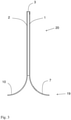
Fig. 1 shows in a side view a composite material according to a first embodiment. -
Fig. 2 shows in a top view of the composite material inFig. 1 . -
Fig. 3 shows a barrier which has been formed from a composite material. -
Fig. 4 shows in a top view a composite material according to an embodiment of the invention. -
Fig. 5 shows in a top view a composite material according to a different embodiment of the invention. -
Fig. 6 shows the composite material ofFig. 4 and 5 in a side view. -
Fig. 7 shows a receptacle according to an embodiment of the invention. -
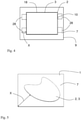
Fig. 8 illustrates schematically a method for applying an adhesive layer on a cover sheet. -
Fig. 9 is a flowchart of a method for production of a composite material. - In the following description of preferred embodiments, the same feature in the different drawings will be denoted with the same reference numeral. It should be noted that the drawings are not to scale.
-
Fig. 1 shows in a side view acomposite material 100.Fig. 2 shows in a top view the composite material ofFig. 1 . The composite material comprises afirst cover sheet 1, asecond cover sheet 2, and acore layer 3 arranged between thefirst cover sheet 1 and thesecond cover sheet 2. Thecore layer 3 comprises a firstadhesive layer 4 in contact with thefirst cover sheet 1, a second adhesive layer 5 in contact with thesecond cover sheet 2, andfibres 6 which extend from the firstadhesive layer 1 to the secondadhesive layer 2. Thefirst cover sheet 1 has a larger extension than thecore layer 3 and comprises afirst edge region 7 free from thecore layer 3, wherein thefirst edge region 7 extends from theouter edge 9 of thefirst cover sheet 1 to thecore layer 3. The extension, i.e. the maximum extension, of thefirst edge region 7 beyond theedge 18 of thecore layer 3 is denoted X inFig. 2 . The maximum extension X of thefirst edge region 7 beyond theedge 18 of thecore layer 3 is at least 20 mm. Thesecond cover sheet 2 comprises asecond edge region 10 which is opposite to thefirst edge region 7 of thefirst cover sheet 1. Thesecond edge region 10 is free from the core layer. Thesecond edge region 10 extends from theouter edge 9 of thesecond cover sheet 2 to thecore layer 3. The extension, i.e. the maximum extension, of thesecond edge region 10 beyond theedge 18 of thecore layer 3 is denoted Y inFig. 2 . As can be seen inFig. 2 thesecond edge region 10 extends mainly along one side of thecore layer 3 and is considerably narrower than thefirst edge region 7. The second cover sheet extends no more than 5 mm beyond theouter edge 18 of thecore layer 3. As can be seen inFig. 2 thecore layer 3 extends almost to the edge of thefirst cover sheet 1 and thesecond cover sheet 2 along the upper and lower side inFig. 2 . The first cover sheet also comprises athird edge region 15 which extends from theouter edge 9 of thefirst cover sheet 1 to thecore layer 3 on the opposite side of thecore layer 3. The extension of thefirst edge region 7 perpendicular to the core layer is at least 20 mm, and preferably at least 50 mm. This allows the edge region to be formed into a side wall of a receptacle or container. -
Fig. 3 shows abarrier 20 which has been formed from a composite material similar to that shown inFig. 1 and Fig. 2 . Thelower end 19 of thebarrier 20 comprises thefirst edge region 7 and thesecond edge region 10. As can be seen inFig. 3 thesecond edge region 10 has the same extension as thefirst edge region 7. As can be seen inFig. 3 thefirst edge region 7 and thesecond edge region 10 have been bent outwards from thecore layer 3 so that the ends of thefirst edge region 7 and thesecond edge region 10 provide a stable support for thebarrier 20 when placed on a surface. Abarrier 20 as shown inFig. 3 may be used in many different ways. One suitable area of application is to use thebarrier 20 in sports using a ball such as indoor soccer. In indoor soccer, it is desirable to keep the ball within thefield using barriers 20. However, it is also desirable to play on fields which are not dedicated to soccer only. Thus, it is desirable to be able to store thebarriers 20 between the different occasions when soccer is played. Thebarrier 20 shown inFig. 3 is very lightweight while at the same time providing sufficient strength for thebarrier 20. The low weight ensures easy handling of thebarriers 20. -
Fig. 4 shows in a top view a different embodiment of a composite material comprising afirst cover sheet 1 and asecond cover sheet 2 and acore layer 3 arranged between thefirst cover sheet 1 and thesecond cover sheet 2.Fig. 5 shows in a top view a different embodiment of a composite material comprising afirst cover sheet 1 and asecond cover sheet 2 and acore layer 3 arranged between thefirst cover sheet 1 and thesecond cover sheet 2. Thesecond cover sheet 2 and thecore layer 3 have a rectangular shape inFig. 4 .Fig. 6 shows the composite material ofFigs. 4 and 5 in a side view. Thefirst cover sheet 1 has a larger extension than thecore layer 3 and comprises afirst edge region 7 free from thecore layer 3. Thefirst edge region 7 extends from theouter edge 9 of thefirst cover sheet 1 to thecore layer 3 and extends around the entireouter edge 9 of thefirst cover sheet 1, so that thefirst edge region 7 encircles thecore layer 3. As can be seen most clearly inFig. 5 , thesecond cover sheet 2 has essentially the same extension as thecore layer 3. Thesecond cover sheet 2 comprises a narrowsecond edge region 10 which is free from thecore layer 3. The second cover sheet extends no more than 5 mm beyond the outer edge of the core layer and preferably no more than 1 mm beyond the outer edge of the core layer, i.e., the third edge region has an extension of no more than 5 mm and preferably no more than 1 mm. Thus, thesecond edge region 10 extends around the entire edge of the first cover sheet, so that thesecond edge region 10 encircles the core layer. The extension of thecore layer 3 is shown with the dottedline 18 inFig. 4 . InFig. 5 thesecond cover sheet 2 has an irregular shape. The shape of the firstadhesive layer 4 and thus the shape of thecore layer 3 may be achieved by providing thefirst cover sheet 1 with a mask (not shown) having the shape of thefirst edge region 7. After having applied the firstadhesive layer 4 the mask is removed leaving thefirst edge region 7 uncovered by adhesive. Thesecond cover sheet 2 is shown to have the same extension as the adhesive layer inFig. 4 . The largest extension of thefirst edge region 7 beyond the edge of thecore layer 3 is denoted X inFig. 5 . - The extension of the core layer is shown as a rectangle in
Fig. 4 . It is, however, possible to provide the core layer shaped as a parallelogram. - In an alternative embodiment composite material comprises
edge regions 28 extending outside thecore layer 3 in small areas as is indicated by the dottedregions 28 inFig. 4 . The dottedregions 28 may be sufficient for attachment to a façade of a building (not shown) when the area defined by thecore layer 3 defines the area of a façade element to be attached to a facade. The extension of the dottedregions 28 beyond the edge of thecore layer 3 is denoted X inFig. 4 . -
Fig. 7 shows areceptacle 21 according to an embodiment of the invention. Thereceptacle 21 has been formed from acomposite material 1 as shown inFig. 4 andFig. 6 . Thefirst edge region 7 has been reformed into aside wall 22 according to anyone ofclaims 2 to 5, wherein thesecond cover 2 sheet forms theinner bottom 23 of thereceptacle 21 and thefirst edge region 7 forms theside wall 22 of thereceptacle 21. In the embodiment shown inFig. 7 thesecond cover sheet 2 is essentially flat. With the term flat is meant that the variation perpendicular to the surface of thesecond cover sheet 2 varies no more than 10 % of the largest extension of thesecond cover sheet 2. The form of thewall 22 as shown inFig. 7 will ensure that sufficient strength is provided through the shape of thewall 22. The strength of theinner bottom 23 of thereceptacle 21 is provided by the sandwich arrangement of thefirst cover sheet 1, thesecond cover sheet 2, and thecore layer 3. -
Fig. 8 illustrates schematically a method for applying anadhesive layer 4, 5, on acover sheet coating head 24 which operates at a distance Da from thefirst cover sheet 1 and thesecond cover sheet 2. Thecoating head 24 comprises aslot 25 through which the adhesive leaves the coating head and through which the adhesive is forced by applying a pressure on the adhesive inside thecoating head 24. The adhesive can be said to be extruded from thecoating head 24 through theslot 25 while moving thecover sheet direction 30. During application of the adhesive layer the adhesive forms a continuous stream from the slot to thecover sheet coating head 24. The distance D is at least the thickness of theadhesive layer 4, 5 plus at least 5 mm, preferably at least 7 mm, and the time period T is less than 5 seconds, preferably less than 0.5 seconds. The pressure P is decreased below ambient pressure. This provides for an abrupt stop in the stream of adhesive. During the application of the adhesive on the cover sheet the distance Da between the coating head and thecover sheet adhesive layer 4, 5. The thickness of theadhesive layer 4, 5, is typically 0.15-0,3. The adhesive is stored in thereservoir 26. The pressure on the adhesive is provided by the pressure means 27. The dotted line shows the coating head 24', the reservoir 26', and the pressure means 27' in the position it has when application of adhesive has been terminated. -
Fig. 9 is a flowchart of amethod 300 for production of acomposite material 100 according to the embodiments ofFigs. 1, 2 ,4, 5 and6 . The method comprises the steps of providing 301 afirst cover sheet 1 and asecond cover sheet 2, applying 302 a firstadhesive layer 4 on thefirst cover sheet 1, applying a second adhesive layer 5 in contact with thesecond cover sheet 2, applying 303 a flocking material in the form of individual fibres on one of or both adhesive layers, arranging the first cover sheet adjacent to the second cover sheet with the first adhesive layer facing the second adhesive layer and with the fibres in contact with the first adhesive layer as well as the second adhesive layer, and providing 305 for the adhesive layers to cure. The firstadhesive layer 4 and the second adhesive layer may be applied in many ways. It is, however, important to provide a well-defined core layer. Thefibres 6 can be of many different materials, such as, e.g., metal or plastic. It is well known in the art how to apply a flocking material in the form offibres 6 on a surface. Thefibres 6 will adhere to the adhesive layer orientated essentially perpendicular to the surface. When thesecond cover sheet 2 is arranged adjacent to thefirst cover sheet 1 with thefibres 6 in contact with the first adhesive layer as well as the secondadhesive layer 2, only curing of the adhesive layers is required to form thecomposite material 100. Thefibres 6 will only adhere to theadhesive layers 4, 5. Thus, the extension of the core layer will be defined by the adhesive layers. For the illustrated embodiment, both adhesive layers have the same extension. Primarily, it is important to avoid that the first adhesive layer is larger than the second adhesive layer as this would lead to the fibres only be adhered to the first cover sheet in some areas. - The composite material may of course have other shapes than those that have been shown in the embodiments above.
Claims (12)
- Composite material (100) comprisinga first cover sheet (1),a second cover sheet (2), anda core layer (3) arranged between the first cover sheet (1) and the second cover sheet (1), said core layer (3) comprising:a first adhesive layer (4) in contact with the first cover sheet (1),a second adhesive layer (5) in contact with the second cover sheet (2), anda flocking material in the form of individual fibres (6) which extend from the first adhesive layer (4) to the second adhesive layer (5),characterized in that the first cover sheet (1) has a larger extension than the core layer (3) and comprises at least a first edge region (7) which is free from the core layer (3),wherein the first edge region (7) extends from an outer edge (9) of the first cover sheet (1) to the core layer (3),wherein the extension of the first edge region (7) is at least 20 mm beyond an outer edge (18) of the core layer (3), andwherein the second cover sheet (2) extends no more than 5 mm beyond the outer edge (18) of the core layer (3).
- Composite material (100) according to claim 1, wherein the extension of the first edge region (7) beyond the outer edge (18) of the core layer (3) is at least 50 mm.
- Composite material (100) according to claim 1 or 2, wherein the first edge region (7) extends around the entire outer edge (9) of the first cover sheet (1), so that the first edge region (7) encircles the core layer (3).
- Composite material (100) according to claim 1, 2 or 3, wherein the second cover sheet (2) extends no more than 1 mm beyond the outer edge (18) of the core layer (3).
- Receptacle (21) formed from a composite material (100) according to anyone of claims 1 to 4, wherein the second cover sheet (2) forms an inner bottom (23) of the receptacle (21) and at least part of the first edge region form side walls (24) of the receptacle (21).
- Method (300) for production of a composite material (100) according to anyone of claims 1-4, comprising the stepsproviding (301) a first cover sheet (1) and a second cover sheet (2),applying (302) a first adhesive layer (4) on the first cover sheet (1) and a second adhesive layer (5) on the second cover sheet (2),applying (303) a flocking material in the form of individual fibres (6) on one of the adhesive layers (4, 5),arranging (304) the first cover sheet (1) adjacent to the second cover sheet (2) with the first adhesive layer (4) facing the second adhesive layer (5) and with the fibres (6) in contact with the first adhesive layer (4) as well as the second adhesive layer (5), providing (305) for the adhesive layers (4, 5) to cure to form a core layer (3) constituted by the first adhesive layer (4) the second adhesive layer (5) and the fibers (6), characterized in that the first cover sheet (1) has a larger extension than the core layer (3) and comprises at least a first edge region (7) which is free from the core layer (3),wherein the first edge region (7) extends from an outer edge (9) of the first cover sheet (1) to the core layer (3),wherein the extension of the first edge region (7) beyond an outer edge (18) of the core layer (3) is at least 20 mm, andwherein the second cover sheet (2) has essentially the same extension as the core layer (3) and extends no more than 5 mm beyond the outer edge (18) of the core layer (3).
- Method according to claim 6, wherein the extension of the first edge region (7) beyond the outer edge (18) of the core layer (3) is at least 50 mm.
- Method according to claim 6 or 7, wherein the first adhesive layer (4) is applied on the first cover sheet (1) and the second adhesive layer (5) is applied on the second cover sheet (2) using a coating head (25) which operates at a distance from the first cover sheet (1) and the second cover sheet (2).
- Method according to claim 6, 7 or 8, wherein the coating head (25) comprises a slot (26) through which the adhesive leaves the coating head (25) and through which the adhesive is forced by applying a pressure on the adhesive inside the coating head (25).
- Method according to claim 9, wherein the application of the adhesive on the respective cover sheets (1, 2) is ended by the steps ofmoving the coating head (25) away from the respective cover sheet (1, 2), andlowering the pressure on the adhesive inside the coating head (25).
- Method according to claim 10, wherein the coating head (25) is moved away from the respective cover sheet (1, 2) at least 5 mm at a speed of at least 200 mm per minute.
- Method according to claim 10 or 11, wherein the pressure on the adhesive inside the coating head (25) is decreased below ambient pressure.
Priority Applications (1)
| Application Number | Priority Date | Filing Date | Title |
|---|---|---|---|
| PL18714630T PL3595891T3 (en) | 2017-03-17 | 2018-03-16 | Composite material and method for production of the same |
Applications Claiming Priority (2)
| Application Number | Priority Date | Filing Date | Title |
|---|---|---|---|
| SE1750323A SE541379C2 (en) | 2017-03-17 | 2017-03-17 | Composite material and method for production of the same |
| PCT/SE2018/050263 WO2018169482A1 (en) | 2017-03-17 | 2018-03-16 | Composite material and method for production of the same |
Publications (2)
| Publication Number | Publication Date |
|---|---|
| EP3595891A1 EP3595891A1 (en) | 2020-01-22 |
| EP3595891B1 true EP3595891B1 (en) | 2022-02-16 |
Family
ID=61832565
Family Applications (1)
| Application Number | Title | Priority Date | Filing Date |
|---|---|---|---|
| EP18714630.3A Active EP3595891B1 (en) | 2017-03-17 | 2018-03-16 | Composite material and method for production of the same |
Country Status (8)
| Country | Link |
|---|---|
| US (1) | US11312101B2 (en) |
| EP (1) | EP3595891B1 (en) |
| CN (1) | CN110709236A (en) |
| DK (1) | DK3595891T3 (en) |
| ES (1) | ES2913748T3 (en) |
| PL (1) | PL3595891T3 (en) |
| SE (1) | SE541379C2 (en) |
| WO (1) | WO2018169482A1 (en) |
Families Citing this family (1)
| Publication number | Priority date | Publication date | Assignee | Title |
|---|---|---|---|---|
| US20220410207A1 (en) * | 2021-06-25 | 2022-12-29 | Toyota Jidosha Kabushiki Kaisha | Method for forming parting line |
Family Cites Families (13)
| Publication number | Priority date | Publication date | Assignee | Title |
|---|---|---|---|---|
| US2276374A (en) * | 1939-07-14 | 1942-03-17 | Derman Harry | Collapsible drawer |
| SE465260B (en) | 1988-03-16 | 1991-08-19 | Scanalma Ab | SANDWICH CONSTRUCTION AND PROCEDURES FOR PREPARING THIS |
| SE506929C2 (en) | 1996-07-04 | 1998-03-02 | Volvo Ab | Construction material in vehicles consisting of moldable, metallic sandwich element |
| EP1274568A2 (en) * | 2000-04-07 | 2003-01-15 | Dofasco Inc. | Multi-dimensional tailored laminate |
| DE10214010A1 (en) * | 2002-03-29 | 2003-10-16 | Hssa Sweden Ab Trollhaettan | Device and method for producing composite materials |
| SE0301319L (en) * | 2003-05-07 | 2004-11-08 | Hssa Sweden Ab | Method for manufacturing composite structures |
| SE0301337D0 (en) * | 2003-05-07 | 2003-05-07 | Hssa Sweden Ab | Deformable elements from composite structures |
| CN201196336Y (en) * | 2008-03-25 | 2009-02-18 | 王贞禄 | Sheet material structure for car body |
| DE102012103332A1 (en) | 2012-04-17 | 2013-10-17 | Thyssenkrupp Steel Europe Ag | Method for producing large lightweight sheets |
| CN202850286U (en) * | 2012-10-25 | 2013-04-03 | 成都市第六建筑工程公司 | Self-thermal insulation enamelled pressed steel plate |
| DE102014116112A1 (en) * | 2014-11-05 | 2016-05-12 | Dr. Ing. H.C. F. Porsche Aktiengesellschaft | cowling |
| CN107428116B (en) | 2015-03-19 | 2020-09-01 | 乐金华奥斯有限公司 | Sandwich board and manufacturing method thereof |
| SG10201505238XA (en) * | 2015-07-01 | 2017-02-27 | Xpac Technologies Pte Ltd | A container assembly |
-
2017
- 2017-03-17 SE SE1750323A patent/SE541379C2/en unknown
-
2018
- 2018-03-16 CN CN201880018911.3A patent/CN110709236A/en active Pending
- 2018-03-16 WO PCT/SE2018/050263 patent/WO2018169482A1/en active Application Filing
- 2018-03-16 PL PL18714630T patent/PL3595891T3/en unknown
- 2018-03-16 ES ES18714630T patent/ES2913748T3/en active Active
- 2018-03-16 DK DK18714630.3T patent/DK3595891T3/en active
- 2018-03-16 EP EP18714630.3A patent/EP3595891B1/en active Active
- 2018-03-16 US US16/494,444 patent/US11312101B2/en active Active
Non-Patent Citations (1)
| Title |
|---|
| None * |
Also Published As
| Publication number | Publication date |
|---|---|
| DK3595891T3 (en) | 2022-05-23 |
| US11312101B2 (en) | 2022-04-26 |
| CN110709236A (en) | 2020-01-17 |
| WO2018169482A1 (en) | 2018-09-20 |
| US20200086607A1 (en) | 2020-03-19 |
| EP3595891A1 (en) | 2020-01-22 |
| ES2913748T3 (en) | 2022-06-06 |
| SE1750323A1 (en) | 2018-09-18 |
| SE541379C2 (en) | 2019-09-10 |
| PL3595891T3 (en) | 2022-07-11 |
Similar Documents
| Publication | Publication Date | Title |
|---|---|---|
| JP2017519663A (en) | Honeycomb core structure | |
| US20070020441A1 (en) | Core for a sandwich panel manufactured by deep drawing and a sandwich panel thereby | |
| EP3595891B1 (en) | Composite material and method for production of the same | |
| EP1458942A1 (en) | Structural component | |
| US4136630A (en) | Sail batten | |
| US8857565B2 (en) | Method for making acoustical panels with a three-dimensional surface | |
| US20130186024A1 (en) | Fiber composite corner bead | |
| US20070273967A1 (en) | Visual Communication Panel And Method For Manufacturing It | |
| KR102236303B1 (en) | Metal Composite Panel Forming Apparatus for Exterior Panel, Bending Method | |
| DE10318072A1 (en) | Compound plate, for a kitchen working surface, has an upper stone plate bonded to a lower carrier plate by an intermediate hard foam layer to reduce the plate weight | |
| DE102011011079A1 (en) | Baseboard for arrangement in transition area of floor covering to wall, has base body and elastic distance unit that is connected with base body | |
| JP4121911B2 (en) | Lattice member and block for earthquake-resistant wall using the same | |
| KR101004011B1 (en) | A stone panel | |
| KR100666845B1 (en) | Core for a sandwich panel manufactured by deep drawing and a sandwich panel thereof | |
| EP1704041B1 (en) | Device and method for producing a shaped part | |
| JPH01214432A (en) | Door board element and manufacture thereof | |
| US20230015309A1 (en) | Metal reinforced board | |
| CN207620358U (en) | A kind of composite high-strength plastic formwork | |
| US20050224164A1 (en) | Method for making a composite board and the composite board made thereby | |
| JP6543093B2 (en) | Panel manufacturing method | |
| WO2013178206A1 (en) | Construction panel | |
| US9095208B1 (en) | Tabletop system | |
| KR100493690B1 (en) | Door of midium density fiberboard | |
| AU2004319030A1 (en) | Process for manufacturing insulating panels with polimeric foam and mineral wool | |
| DE29908136U1 (en) | Disc-shaped cut as an insert in a baking pan |
Legal Events
| Date | Code | Title | Description |
|---|---|---|---|
| STAA | Information on the status of an ep patent application or granted ep patent |
Free format text: STATUS: UNKNOWN |
|
| STAA | Information on the status of an ep patent application or granted ep patent |
Free format text: STATUS: THE INTERNATIONAL PUBLICATION HAS BEEN MADE |
|
| PUAI | Public reference made under article 153(3) epc to a published international application that has entered the european phase |
Free format text: ORIGINAL CODE: 0009012 |
|
| STAA | Information on the status of an ep patent application or granted ep patent |
Free format text: STATUS: REQUEST FOR EXAMINATION WAS MADE |
|
| 17P | Request for examination filed |
Effective date: 20190911 |
|
| AK | Designated contracting states |
Kind code of ref document: A1 Designated state(s): AL AT BE BG CH CY CZ DE DK EE ES FI FR GB GR HR HU IE IS IT LI LT LU LV MC MK MT NL NO PL PT RO RS SE SI SK SM TR |
|
| AX | Request for extension of the european patent |
Extension state: BA ME |
|
| DAV | Request for validation of the european patent (deleted) | ||
| DAX | Request for extension of the european patent (deleted) | ||
| GRAP | Despatch of communication of intention to grant a patent |
Free format text: ORIGINAL CODE: EPIDOSNIGR1 |
|
| STAA | Information on the status of an ep patent application or granted ep patent |
Free format text: STATUS: GRANT OF PATENT IS INTENDED |
|
| INTG | Intention to grant announced |
Effective date: 20210323 |
|
| GRAJ | Information related to disapproval of communication of intention to grant by the applicant or resumption of examination proceedings by the epo deleted |
Free format text: ORIGINAL CODE: EPIDOSDIGR1 |
|
| STAA | Information on the status of an ep patent application or granted ep patent |
Free format text: STATUS: REQUEST FOR EXAMINATION WAS MADE |
|
| INTC | Intention to grant announced (deleted) | ||
| GRAP | Despatch of communication of intention to grant a patent |
Free format text: ORIGINAL CODE: EPIDOSNIGR1 |
|
| STAA | Information on the status of an ep patent application or granted ep patent |
Free format text: STATUS: GRANT OF PATENT IS INTENDED |
|
| INTG | Intention to grant announced |
Effective date: 20210928 |
|
| GRAS | Grant fee paid |
Free format text: ORIGINAL CODE: EPIDOSNIGR3 |
|
| GRAA | (expected) grant |
Free format text: ORIGINAL CODE: 0009210 |
|
| STAA | Information on the status of an ep patent application or granted ep patent |
Free format text: STATUS: THE PATENT HAS BEEN GRANTED |
|
| AK | Designated contracting states |
Kind code of ref document: B1 Designated state(s): AL AT BE BG CH CY CZ DE DK EE ES FI FR GB GR HR HU IE IS IT LI LT LU LV MC MK MT NL NO PL PT RO RS SE SI SK SM TR |
|
| REG | Reference to a national code |
Ref country code: GB Ref legal event code: FG4D |
|
| REG | Reference to a national code |
Ref country code: CH Ref legal event code: EP |
|
| REG | Reference to a national code |
Ref country code: DE Ref legal event code: R096 Ref document number: 602018030885 Country of ref document: DE |
|
| REG | Reference to a national code |
Ref country code: AT Ref legal event code: REF Ref document number: 1468647 Country of ref document: AT Kind code of ref document: T Effective date: 20220315 |
|
| REG | Reference to a national code |
Ref country code: IE Ref legal event code: FG4D |
|
| REG | Reference to a national code |
Ref country code: FI Ref legal event code: FGE |
|
| REG | Reference to a national code |
Ref country code: DK Ref legal event code: T3 Effective date: 20220518 |
|
| REG | Reference to a national code |
Ref country code: SE Ref legal event code: TRGR |
|
| REG | Reference to a national code |
Ref country code: ES Ref legal event code: FG2A Ref document number: 2913748 Country of ref document: ES Kind code of ref document: T3 Effective date: 20220606 |
|
| REG | Reference to a national code |
Ref country code: NO Ref legal event code: T2 Effective date: 20220216 |
|
| REG | Reference to a national code |
Ref country code: LT Ref legal event code: MG9D |
|
| REG | Reference to a national code |
Ref country code: NL Ref legal event code: MP Effective date: 20220216 |
|
| REG | Reference to a national code |
Ref country code: AT Ref legal event code: MK05 Ref document number: 1468647 Country of ref document: AT Kind code of ref document: T Effective date: 20220216 |
|
| PG25 | Lapsed in a contracting state [announced via postgrant information from national office to epo] |
Ref country code: RS Free format text: LAPSE BECAUSE OF FAILURE TO SUBMIT A TRANSLATION OF THE DESCRIPTION OR TO PAY THE FEE WITHIN THE PRESCRIBED TIME-LIMIT Effective date: 20220216 Ref country code: PT Free format text: LAPSE BECAUSE OF FAILURE TO SUBMIT A TRANSLATION OF THE DESCRIPTION OR TO PAY THE FEE WITHIN THE PRESCRIBED TIME-LIMIT Effective date: 20220616 Ref country code: NL Free format text: LAPSE BECAUSE OF FAILURE TO SUBMIT A TRANSLATION OF THE DESCRIPTION OR TO PAY THE FEE WITHIN THE PRESCRIBED TIME-LIMIT Effective date: 20220216 Ref country code: LT Free format text: LAPSE BECAUSE OF FAILURE TO SUBMIT A TRANSLATION OF THE DESCRIPTION OR TO PAY THE FEE WITHIN THE PRESCRIBED TIME-LIMIT Effective date: 20220216 Ref country code: HR Free format text: LAPSE BECAUSE OF FAILURE TO SUBMIT A TRANSLATION OF THE DESCRIPTION OR TO PAY THE FEE WITHIN THE PRESCRIBED TIME-LIMIT Effective date: 20220216 Ref country code: BG Free format text: LAPSE BECAUSE OF FAILURE TO SUBMIT A TRANSLATION OF THE DESCRIPTION OR TO PAY THE FEE WITHIN THE PRESCRIBED TIME-LIMIT Effective date: 20220516 |
|
| PG25 | Lapsed in a contracting state [announced via postgrant information from national office to epo] |
Ref country code: LV Free format text: LAPSE BECAUSE OF FAILURE TO SUBMIT A TRANSLATION OF THE DESCRIPTION OR TO PAY THE FEE WITHIN THE PRESCRIBED TIME-LIMIT Effective date: 20220216 Ref country code: GR Free format text: LAPSE BECAUSE OF FAILURE TO SUBMIT A TRANSLATION OF THE DESCRIPTION OR TO PAY THE FEE WITHIN THE PRESCRIBED TIME-LIMIT Effective date: 20220517 Ref country code: AT Free format text: LAPSE BECAUSE OF FAILURE TO SUBMIT A TRANSLATION OF THE DESCRIPTION OR TO PAY THE FEE WITHIN THE PRESCRIBED TIME-LIMIT Effective date: 20220216 |
|
| PG25 | Lapsed in a contracting state [announced via postgrant information from national office to epo] |
Ref country code: IS Free format text: LAPSE BECAUSE OF FAILURE TO SUBMIT A TRANSLATION OF THE DESCRIPTION OR TO PAY THE FEE WITHIN THE PRESCRIBED TIME-LIMIT Effective date: 20220617 |
|
| PG25 | Lapsed in a contracting state [announced via postgrant information from national office to epo] |
Ref country code: SM Free format text: LAPSE BECAUSE OF FAILURE TO SUBMIT A TRANSLATION OF THE DESCRIPTION OR TO PAY THE FEE WITHIN THE PRESCRIBED TIME-LIMIT Effective date: 20220216 Ref country code: SK Free format text: LAPSE BECAUSE OF FAILURE TO SUBMIT A TRANSLATION OF THE DESCRIPTION OR TO PAY THE FEE WITHIN THE PRESCRIBED TIME-LIMIT Effective date: 20220216 Ref country code: RO Free format text: LAPSE BECAUSE OF FAILURE TO SUBMIT A TRANSLATION OF THE DESCRIPTION OR TO PAY THE FEE WITHIN THE PRESCRIBED TIME-LIMIT Effective date: 20220216 Ref country code: EE Free format text: LAPSE BECAUSE OF FAILURE TO SUBMIT A TRANSLATION OF THE DESCRIPTION OR TO PAY THE FEE WITHIN THE PRESCRIBED TIME-LIMIT Effective date: 20220216 Ref country code: CZ Free format text: LAPSE BECAUSE OF FAILURE TO SUBMIT A TRANSLATION OF THE DESCRIPTION OR TO PAY THE FEE WITHIN THE PRESCRIBED TIME-LIMIT Effective date: 20220216 |
|
| REG | Reference to a national code |
Ref country code: CH Ref legal event code: PL |
|
| REG | Reference to a national code |
Ref country code: DE Ref legal event code: R097 Ref document number: 602018030885 Country of ref document: DE |
|
| PG25 | Lapsed in a contracting state [announced via postgrant information from national office to epo] |
Ref country code: MC Free format text: LAPSE BECAUSE OF FAILURE TO SUBMIT A TRANSLATION OF THE DESCRIPTION OR TO PAY THE FEE WITHIN THE PRESCRIBED TIME-LIMIT Effective date: 20220216 Ref country code: AL Free format text: LAPSE BECAUSE OF FAILURE TO SUBMIT A TRANSLATION OF THE DESCRIPTION OR TO PAY THE FEE WITHIN THE PRESCRIBED TIME-LIMIT Effective date: 20220216 |
|
| REG | Reference to a national code |
Ref country code: BE Ref legal event code: MM Effective date: 20220331 |
|
| PLBE | No opposition filed within time limit |
Free format text: ORIGINAL CODE: 0009261 |
|
| STAA | Information on the status of an ep patent application or granted ep patent |
Free format text: STATUS: NO OPPOSITION FILED WITHIN TIME LIMIT |
|
| 26N | No opposition filed |
Effective date: 20221117 |
|
| PG25 | Lapsed in a contracting state [announced via postgrant information from national office to epo] |
Ref country code: LU Free format text: LAPSE BECAUSE OF NON-PAYMENT OF DUE FEES Effective date: 20220316 Ref country code: LI Free format text: LAPSE BECAUSE OF NON-PAYMENT OF DUE FEES Effective date: 20220331 Ref country code: IE Free format text: LAPSE BECAUSE OF NON-PAYMENT OF DUE FEES Effective date: 20220316 Ref country code: CH Free format text: LAPSE BECAUSE OF NON-PAYMENT OF DUE FEES Effective date: 20220331 |
|
| PG25 | Lapsed in a contracting state [announced via postgrant information from national office to epo] |
Ref country code: SI Free format text: LAPSE BECAUSE OF FAILURE TO SUBMIT A TRANSLATION OF THE DESCRIPTION OR TO PAY THE FEE WITHIN THE PRESCRIBED TIME-LIMIT Effective date: 20220216 Ref country code: BE Free format text: LAPSE BECAUSE OF NON-PAYMENT OF DUE FEES Effective date: 20220331 |
|
| PGFP | Annual fee paid to national office [announced via postgrant information from national office to epo] |
Ref country code: NO Payment date: 20230317 Year of fee payment: 6 Ref country code: FR Payment date: 20230314 Year of fee payment: 6 Ref country code: FI Payment date: 20230315 Year of fee payment: 6 Ref country code: DK Payment date: 20230316 Year of fee payment: 6 |
|
| PGFP | Annual fee paid to national office [announced via postgrant information from national office to epo] |
Ref country code: SE Payment date: 20230314 Year of fee payment: 6 Ref country code: PL Payment date: 20230217 Year of fee payment: 6 Ref country code: GB Payment date: 20230317 Year of fee payment: 6 Ref country code: DE Payment date: 20230323 Year of fee payment: 6 |
|
| PG25 | Lapsed in a contracting state [announced via postgrant information from national office to epo] |
Ref country code: IT Free format text: LAPSE BECAUSE OF FAILURE TO SUBMIT A TRANSLATION OF THE DESCRIPTION OR TO PAY THE FEE WITHIN THE PRESCRIBED TIME-LIMIT Effective date: 20220216 |
|
| PGFP | Annual fee paid to national office [announced via postgrant information from national office to epo] |
Ref country code: ES Payment date: 20230412 Year of fee payment: 6 |
|
| PG25 | Lapsed in a contracting state [announced via postgrant information from national office to epo] |
Ref country code: MK Free format text: LAPSE BECAUSE OF FAILURE TO SUBMIT A TRANSLATION OF THE DESCRIPTION OR TO PAY THE FEE WITHIN THE PRESCRIBED TIME-LIMIT Effective date: 20220216 Ref country code: CY Free format text: LAPSE BECAUSE OF FAILURE TO SUBMIT A TRANSLATION OF THE DESCRIPTION OR TO PAY THE FEE WITHIN THE PRESCRIBED TIME-LIMIT Effective date: 20220216 |
|
| PGFP | Annual fee paid to national office [announced via postgrant information from national office to epo] |
Ref country code: FI Payment date: 20240319 Year of fee payment: 7 Ref country code: DE Payment date: 20240319 Year of fee payment: 7 Ref country code: GB Payment date: 20240318 Year of fee payment: 7 |