EP3595084A1 - Justierungsvorrichtung für antennenabwärtsneigung und kommunikationsvorrichtung - Google Patents
Justierungsvorrichtung für antennenabwärtsneigung und kommunikationsvorrichtung Download PDFInfo
- Publication number
- EP3595084A1 EP3595084A1 EP17902715.6A EP17902715A EP3595084A1 EP 3595084 A1 EP3595084 A1 EP 3595084A1 EP 17902715 A EP17902715 A EP 17902715A EP 3595084 A1 EP3595084 A1 EP 3595084A1
- Authority
- EP
- European Patent Office
- Prior art keywords
- transmission
- transmission assembly
- antenna
- assembly
- transmission element
- Prior art date
- Legal status (The legal status is an assumption and is not a legal conclusion. Google has not performed a legal analysis and makes no representation as to the accuracy of the status listed.)
- Granted
Links
Images







Classifications
-
- H—ELECTRICITY
- H01—ELECTRIC ELEMENTS
- H01Q—ANTENNAS, i.e. RADIO AERIALS
- H01Q1/00—Details of, or arrangements associated with, antennas
- H01Q1/12—Supports; Mounting means
- H01Q1/22—Supports; Mounting means by structural association with other equipment or articles
- H01Q1/24—Supports; Mounting means by structural association with other equipment or articles with receiving set
- H01Q1/241—Supports; Mounting means by structural association with other equipment or articles with receiving set used in mobile communications, e.g. GSM
- H01Q1/246—Supports; Mounting means by structural association with other equipment or articles with receiving set used in mobile communications, e.g. GSM specially adapted for base stations
-
- H—ELECTRICITY
- H01—ELECTRIC ELEMENTS
- H01Q—ANTENNAS, i.e. RADIO AERIALS
- H01Q1/00—Details of, or arrangements associated with, antennas
- H01Q1/12—Supports; Mounting means
- H01Q1/125—Means for positioning
-
- H—ELECTRICITY
- H01—ELECTRIC ELEMENTS
- H01Q—ANTENNAS, i.e. RADIO AERIALS
- H01Q3/00—Arrangements for changing or varying the orientation or the shape of the directional pattern of the waves radiated from an antenna or antenna system
- H01Q3/26—Arrangements for changing or varying the orientation or the shape of the directional pattern of the waves radiated from an antenna or antenna system varying the relative phase or relative amplitude of energisation between two or more active radiating elements; varying the distribution of energy across a radiating aperture
- H01Q3/30—Arrangements for changing or varying the orientation or the shape of the directional pattern of the waves radiated from an antenna or antenna system varying the relative phase or relative amplitude of energisation between two or more active radiating elements; varying the distribution of energy across a radiating aperture varying the relative phase between the radiating elements of an array
- H01Q3/32—Arrangements for changing or varying the orientation or the shape of the directional pattern of the waves radiated from an antenna or antenna system varying the relative phase or relative amplitude of energisation between two or more active radiating elements; varying the distribution of energy across a radiating aperture varying the relative phase between the radiating elements of an array by mechanical means
-
- H—ELECTRICITY
- H01—ELECTRIC ELEMENTS
- H01Q—ANTENNAS, i.e. RADIO AERIALS
- H01Q5/00—Arrangements for simultaneous operation of antennas on two or more different wavebands, e.g. dual-band or multi-band arrangements
- H01Q5/30—Arrangements for providing operation on different wavebands
-
- H—ELECTRICITY
- H04—ELECTRIC COMMUNICATION TECHNIQUE
- H04W—WIRELESS COMMUNICATION NETWORKS
- H04W16/00—Network planning, e.g. coverage or traffic planning tools; Network deployment, e.g. resource partitioning or cells structures
- H04W16/24—Cell structures
- H04W16/28—Cell structures using beam steering
-
- H—ELECTRICITY
- H01—ELECTRIC ELEMENTS
- H01Q—ANTENNAS, i.e. RADIO AERIALS
- H01Q19/00—Combinations of primary active antenna elements and units with secondary devices, e.g. with quasi-optical devices, for giving the antenna a desired directional characteristic
- H01Q19/10—Combinations of primary active antenna elements and units with secondary devices, e.g. with quasi-optical devices, for giving the antenna a desired directional characteristic using reflecting surfaces
Definitions
- This application relates to the field of communications technologies, and specifically, to an antenna downtilt adjustment apparatus.
- a multi-band antenna With limitation on a site resource of a mobile base station, a multi-band antenna is increasingly demanded.
- the multi-band antenna is already a mainstream application. Because of strength of a mechanical part (such as a pole or a tower) bearing the multi-band antenna, a structure size, especially a length and a width of the antenna needs to be as small as possible, to reduce wind load and weight. Therefore, smaller space occupied by a downtilt adjustment apparatus disposed inside the multi-band antenna is more conducive to reducing a size of the multi-band antenna.
- a mainstream downtilt adjustment apparatus is transmitted and connected by using a rigid mechanical part, and cannot be flexibly disposed inside the antenna.
- the mainstream downtilt adjustment apparatus occupies large space inside the antenna, and has low transmission efficiency.
- Embodiments of this application provide an antenna downtilt adjustment apparatus and a communications device.
- the antenna downtilt adjustment apparatus has an advantage of flexible disposition, and can reduce a quantity of times of transfer connections and improve transmission efficiency.
- the transmission element transmits a straight pull force or a rotational force between the first transmission assembly and the second transmission assembly.
- the mounting plate is a metal reflection plate, to reflect an antenna signal.
- the transmission element is insulated from the mounting plate, to isolate the transmission element from an antenna, and to ensure an effect of receiving and sending a signal by the antenna.
- the transmission element includes a transmission component and an insulated sleeve wrapped around a periphery of the transmission component.
- the insulated sleeve is wrapped around the periphery of the transmission component, to isolate the transmission component from the outside. Disposition of the insulated sleeve can isolate the transmission element from another component (for example, a component of the antenna) on the mounting plate, to avoid intermodulation.
- the guiding element includes a securing part, a connecting part, and a mating part.
- the securing part is configured to be securely connected to the mounting plate
- the connecting part is connected between the securing part and the mating part
- the mating part is configured to mate with the transmission element, to guide and support installation of the transmission element on the mounting plate.
- the connecting part is disposed between the mating part and the securing part, to absorb a vibration generated during a working process of the transmission element, thereby reducing impact of the vibration on the antenna.
- a through hole is provided in the connecting part, and the through hole is provided between the mating part and the securing part.
- the provision of the through hole increases flexibility of the connecting part, and improves an effect of absorbing the vibration.
- a material of the connecting part is a material having a buffer function, for example, silica gel.
- a buffer function for example, silica gel.
- the antenna downtilt adjustment apparatus further includes a reset assembly.
- the reset assembly is elastically connected between the transmission element and the second transmission assembly, and is configured to provide a reset force for the transmission element.
- the reset assembly includes a spring and a securing block.
- the securing block is secured to the mounting plate, and installation space is provided between the securing block and the second transmission assembly.
- the spring is sleeved around a periphery of the transmission element and is accommodated in the installation space. One end of the spring is secured to the securing block, and the other end of the spring is secured to the second transmission assembly or the transmission element.
- One part of the transmission element for sleeving of the spring and the other part of the transmission element may be of an integrated structure.
- a guiding rod may be secured to one end of the transmission element, and the spring may be sleeved around a periphery of the guiding rod.
- the guiding rod may be designed as a telescopic rod. A length of the guiding rod can be adjusted, and an elastic force of the spring may be adjusted by adjusting the length of the guiding rod.
- a control plate and a communications interface and a motor that are electrically connected to the control plate are disposed in the antenna information management module.
- the communications interface is configured to receive a control signal from a base station.
- the control plate drives the motor after processing the control signal, and the motor is configured to drive the first transmission assembly.
- the first transmission assembly includes a motor interface, the motor interface is connected to the motor of the antenna information management module, to transmit a driving force of the motor; and the antenna information management module drives the first transmission assembly by using the motor.
- the second transmission assembly is a straight pull rod.
- One end of the straight pull rod is secured to the transmission element, and the other end is secured to the phase shifter.
- the first transmission assembly drives the transmission element to move, to push or pull the straight pull rod.
- the first transmission assembly drives the transmission element to rotate.
- the second transmission assembly includes a worm and worm wheel assembly. A rotational motion of the transmission element drives a rotational motion of the second transmission assembly, and drives the phase shifter to rotate.
- the second transmission assembly is a push and pull rod.
- a conversion assembly is disposed between the second transmission assembly and the transmission element. The first transmission assembly drives the transmission element to rotate, and the conversion assembly converts the rotational motion of the transmission element into a direct motion, to drive the second transmission assembly to move in a straight line.
- the conversion assembly includes a worm wheel, a worm, a gear, and a gear rack.
- the worm is connected to the transmission element
- the gear rack is connected to the second transmission assembly
- the worm wheel shares a shaft with the gear.
- the transmission element drives the worm to rotate, drives the gear to rotate through mating of the worm and the worm wheel and synchronous rotation of the worm wheel and the gear, and drives the second transmission assembly to move in a straight line through mating of the gear and the gear rack.
- phase shifters there are at least two phase shifters and at least two second transmission assemblies.
- Each of the second transmission assemblies drives one phase shifter, to form a one-to-one correspondence.
- the transmission element is connected to the at least two second transmission assemblies.
- phase shifters there are at least two phase shifters, at least two second transmission assemblies, and at least two transmission elements.
- Each of the second transmission assemblies is connected between one transmission element and one phase shifter.
- a combiner module is disposed between the at least two transmission elements and the first transmission assembly, and the combiner module is configured to implement conversion between the first transmission assembly and the at least two transmission elements.
- the combiner module includes one input shaft and at least two output shafts.
- the input shaft is connected to the first transmission assembly, and the at least two output shafts are separately connected to the at least two transmission elements.
- a force between the input shaft and the at least two output shafts is transmitted by using a gear.
- this application further provides a communications device, including a base station and the foregoing antenna downtilt adjustment apparatus.
- An antenna information management module of the antenna downtilt adjustment apparatus is communicatively connected the base station, to receive a control signal from the base station, adjust an antenna downtilt, and report adjustment information to the base station.
- the transmission element of the flexible transmission assembly is in an integrated long strip shape, so that the flexible transmission assembly transmits a force between the first transmission assembly and the second transmission assembly.
- the transmission element in an integrated long strip shape can reduce a quantity of times of transfer connections between the first transmission assembly and the second transmission assembly, and improve transmission efficiency.
- the transmission element is bendable, and therefore installation of the transmission element on the mounting plate is more flexible through mating of the transmission element and the guiding element. If there is a component that needs to be avoided on the extension path of the transmission element, the transmission element may be bent as required. In this way, the transmission element can be extended in an open area on the mounting plate.
- An embodiment of this application provides an antenna downtilt adjustment apparatus installed inside an antenna apparatus.
- the antenna apparatus is usually installed on a pole or a tower, and is communicatively connected to a base station.
- the base station is a part that connects a terminal to a wireless network, and may also be referred to as a radio access network (Radio Access Network, RAN) node, or a node or device that connects a terminal to a wireless network.
- RAN Radio Access Network
- the base station described in this application may also be another radio access network node, for example, a transmission reception point (Transmission Reception Point, TRP), an evolved NodeB (evolved Node B, eNB), a radio network controller (radio network controller, RNC), a node B (Node B, NB), a base station controller (Base Station Controller, BSC), a home base station (for example, Home evolved NodeB or Home Node B, HNB), a baseband unit (BaseBand Unit, BBU), or a Wi-Fi access point (Access Point, AP).
- TRP Transmission Reception Point
- eNB evolved NodeB
- RNC radio network controller
- Node B Node B
- BSC Base Station Controller
- BSC Base Station Controller
- HNB Home evolved NodeB or Home Node B, HNB
- BBU Baseband unit
- Wi-Fi access point Access Point, AP
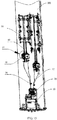
- an antenna downtilt adjustment apparatus including: an antenna information management module 10, a first transmission assembly 20, a flexible transmission assembly 30, a second transmission assembly 40, and a phase shifter 50.
- the antenna information management module 10 is communicatively connected to a base station, and is configured to receive a control signal from the base station (for example, a signal sent by the base station indicates setting an antenna downtilt to 2 degrees) and drive the first transmission assembly 20 according to the control signal, so that the first transmission assembly 20 drives the flexible transmission assembly 30 to move.
- the flexible transmission assembly 30 transmits a force to the second transmission assembly 40, to further drive the phase shifter 50 to work.
- the antenna downtilt adjustment apparatus includes a mounting plate 101 disposed in a housing (such as an antenna radome).
- a housing such as an antenna radome.
- an antenna specifically, a radiating element of the antenna is disposed on one side (side A) of the mounting plate 101.
- a transceiver circuit or a feeding circuit of the antenna may be disposed on another side (side B) of the mounting plate 101.
- the antenna information management module 10, the first transmission assembly 20, the flexible transmission assembly 30, the second transmission assembly 40, and the phase shifter 50 may be disposed on the side B of the mounting plate 101.
- the side A and the side B are two sides or two facets of the mounting plate.
- the antenna information management module 10 and the phase shifter 50 are located on the side B of the mounting plate 101 and each are close to one of two opposite ends of the mounting plate 101.
- the phase shifter 50 is connected to the radiating element of the antenna on the side A of the mounting plate 101.
- the phase shifter 50 is configured to adjust the antenna downtilt.
- the mounting plate 101 is of a metal plate structure, to serve as a reflector of the antenna.
- the mounting plate 101 is an insulation plate, and a surface of one side of the mounting plate 101 on which the antenna is disposed is coated with a reflection layer (such as a metal layer), to reflect an antenna signal.
- the insulation plate can isolate apparatuses (such as the antenna information management module 10, the first transmission assembly 20, the flexible transmission assembly 30, the second transmission assembly 40, and the phase shifter 50) disposed on the other side of the antenna from the antenna, to ensure an effect of receiving and sending a signal by the antenna.
- FIG. 2 schematically depicts a disposition architecture of the flexible transmission assembly 30 on the mounting plate 101.
- the flexible transmission assembly 30 provided in this embodiment of this application includes a transmission element 32 and a guiding element 34.
- the transmission element 32 is in an integrated long strip shape, and the transmission element 32 is bendable. One end of the transmission element 32 mates with the first transmission assembly 20, and the other end of the transmission element 32 mates with the second transmission assembly 40.
- the transmission element 32 is connected between the first transmission assembly 20 and the second transmission assembly 40. Because the transmission element 32 is bendable, an extension path of the transmission element 32 on the mounting plate 101 is more flexible.
- the transmission element 32 may be flexibly disposed depending on a specific space of the mounting plate 101. If a position needs to be avoided, the transmission element 32 only needs to be bent.
- the transmission element 32 is a steel rope, and the transmission element 32 that is in a form of a steel rope can transmit push and pull forces.
- the steel rope is bendable when a force is applied in a direction perpendicular to a length direction of the steel rope. If a push force or a pull force is applied to one end of the steel rope e, the steel rope can transmit the force from one end to the other end.
- the transmission element 32 is a flexible core shaft, and is configured to transmit a rotational force.
- the flexible core shaft is easy to bend. After the guiding element 34 constraints an extension path of the flexible core shaft, a rotational force is applied to one end of the flexible core shaft, to enable the flexible core shaft to rotate.
- the flexible core shaft transmits a rotational force from one end to the other end, and therefore the other end of the flexible core shaft also rotates.
- an isolation component is disposed between the transmission element 32 and the mounting plate 101, to isolate the transmission element 32 from the mounting plate 101.
- an insulation layer may be disposed on a surface of the mounting plate 101 on which the transmission element 32 is disposed.
- an outer surface of the transmission element 32 is set to be insulated.
- the transmission element 32 includes a transmission component and an insulated sleeve wrapped around a periphery of the transmission component. To ensure strength of the transmission component, the transmission component is made of a metal material.
- the insulated sleeve is wrapped around the periphery of the transmission component, to insulate the transmission component from the mounting plate 101, and can also isolate the transmission element 32 from another element (such as a component of an antenna) on the mounting plate 101, to reduce intermodulation (such as passive intermodulation, also referred to as intermodulation distortion, caused by nonlinear characteristics of passive components in a radio frequency system).
- intermodulation such as passive intermodulation, also referred to as intermodulation distortion, caused by nonlinear characteristics of passive components in a radio frequency system.
- FIG. 3 and FIG. 4 show two guiding elements 34 of different structures.
- the guiding element 34 includes a securing part 341, a connecting part 342, and a mating part 343.
- the securing part 341 is configured to be securely connected to the mounting plate 101
- the connecting part 342 is connected between the securing part 341 and the mating part 343, and the mating part 343 is configured to mate with the transmission element 32, to guide and support installation of the transmission element 32 on the mounting plate 101.
- the guiding element 34 may be made of a metal material, or may be made of a plastic material.
- a vibration may be generated during a working process of the transmission element 32.
- the mating part 343 is in direct contact with the transmission element 32, and is greatly affected by the vibration.
- the vibration may be transmitted to the connecting part 342, and the connecting part 342 can absorb a part of the vibration, thereby reducing impact of the vibration on the securing part 341. In other words, impact of the vibration on the mounting plate 101 is reduced.
- the antenna is disposed on the mounting plate 101, and the connection part 342 absorbs a part of the vibration. This reduces impact of the vibration generated on the antenna during the working process of the transmission element 32, thereby ensuring antenna performance.
- a through hole 3421 is provided in the connection part 342, and the through hole 3421 is provided between the mating part 343 and the securing part 341.
- the provision of the through hole 3421 is conducive to increasing elasticity of the connecting part 342 and increasing isolation between the mating part 343 and the securing part 341. In this way, the connecting part 342 absorbs more vibrations and reduces impact of a motion of the transmission element 32 on the mounting plate 101.
- the connecting part 342 serves as a rib connected between the securing part 341 and the mating part 343.
- a shape of the through hole 3421 is not limited herein.
- materials of the mating part 343 and the securing part 341 are rigid, to implement stability of a connection between the mating part 343 and the transmission element 32 and stability of a connection between the securing part 341 and the mounting plate 101.
- a material of the connecting part 342 is a material having a buffer function, for example, silica gel. An effect of absorbing the vibration generated by the transmission element 32 of the connecting part 342 is enhanced by selecting the material.
- the securing part 341 of the guiding element 34 shown in FIG. 3 is of a snap-fit structure.
- the guiding element 34 is installed on the mounting plate 101 through mating of a snap and a hook on the mounting plate 101.
- the securing part 341 of the guiding element 34 shown in FIG. 4 is of a screw assembly structure.
- a pair of screw holes is provided on the securing part 341, and the guiding element 34 is secured to the mounting plate 101 by screwing bolts into the pair of screw holes.
- FIG. 5 shows an internal structure of the antenna information management module 10.
- a control plate 12 and a communications interface 14 and a motor 16 that are electrically connected to the control plate 12 are disposed in the antenna information management module 10.
- the communications interface 14 is configured to be communicatively connected to a base station, to receive a control signal from the base station.
- a main control device (such as an RRU, namely, Remote Radio Unit, remote radio unit) of a mobile base station is connected to the communications interface 14 by using a cable assembly, and the communications interface 14 of the antenna information management module 10 may be an AISG connector.
- the control plate 12 drives the motor 16 to work after processing the control signal.
- the motor 16 includes a first motor 162 and a second motor 164. Both the first motor 162 and the second motor 164 are connected to the first transmission assembly 20 by using a mechanical structure disposed on a shaft end of the motor, to drive the first transmission assembly 20 to move.
- FIG. 6A is a schematic structural diagram of the first transmission assembly 20.
- the first transmission assembly 20 includes a first shaft 21 and a second shaft 22.
- the first shaft 21 and the second shaft 22 are connected to the first motor 162 and the second motor 164, respectively.
- Motor interfaces are disposed at an end of the first shaft 21 and an end of the second shaft 22, and the motor interfaces are configured to plug in and mate with transfer interfaces of the first motor 162 and the second motor 164, to accept a force from the antenna information management module 10.
- the first transmission assembly 20 is connected to the transmission element 32, to drive the transmission element 32 to move in a straight line or rotate.
- the first transmission assembly 20 further includes a plurality of transmission screws 23, and each transmission screw 23 is connected to one transmission element 32.
- a force connection is formed between the motor interface and the transmission screw 23 by using a transmission shaft (namely, the first shaft 21) and a gear assembly.
- the gear assembly includes a planetary carrier gear 24, a planetary gear 25, and a plurality of transmission gears 26.
- a first gear 212 that meshes with the planetary gear 25 is disposed on the first shaft 21, and the planetary carrier gear 24 is also disposed on the first shaft 21.
- the planetary carrier gear 24 shares a shaft with the first gear 212.
- the first gear 212 is obscured by the planetary carrier gear 24, while in FIG. 6B , the planetary carrier gear 24 is hidden, and the first gear 212 is visible.
- Rotation of the first shaft 21 drives the first gear 212 and the planetary carrier gear 24 to rotate.
- the planetary gear 25 is secured to the planetary carrier gear 24 by using a rotation center shaft 252.
- the rotation center shaft 252 follows rotation of the planetary carrier gear 24, so that the planetary gear 25 revolves.
- the first gear 212 drives the planetary gear 25 to autorotate around the rotation center shaft 252.
- the plurality of transmission gears 26 are circularly disposed around a periphery of the planetary gear 25. Rotation angles of the planetary gear 25 correspond to different transmission gears 26. In this way, the planetary gear 25 meshes with different transmission gears 26, to select different transmission gears 26.
- the transmission gears 26 are configured to drive the transmission screws 23.
- the first transmission assembly 20 further includes a transmission nut 27 and a transmission guiding rod 28 that mate with the transmission screw 23, and the transmission nut 27 is connected to the transmission guiding rod 28. Rotation of the transmission screw 23 drives the transmission nut 27 to move in a straight line along the transmission guiding rod 28.
- the transmission nut 27 is connected to the transmission element 32, to drive the transmission element 32 to move in a straight line, so that the transmission element 32 transmits a straight pull force between the first transmission assembly 20 and the second transmission assembly 40.
- the transmission screw 23 may be directly connected to the transmission element 32. In this way, rotation of the transmission screw 23 drives the transmission element 32 to rotate, so that the transmission element 32 transmits a rotational force between the first transmission assembly 20 and the second transmission assembly 40.
- the first transmission assembly 20 may not include the transmission screw 23, the transmission nut 27, and the transmission guiding rod 28, and directly use rotation of the transmission gear 26 to drive the transmission element 32 to rotate.
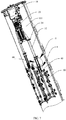
- a transmission relationship between the transmission element 32 and the second transmission assembly 40 may be: a push and pull straight line translation (as shown in FIG. 7 ), a rotational motion of the transmission element 32 being converted into a rotational motion of the second transmission assembly 40 (as shown in FIG. 10 and FIG. 11 ), or a rotational motion of the transmission element 32 being converted into a straight line translation of the second transmission assembly 40 (as shown in FIG. 15 ).
- the second transmission assembly 40 is a straight pull rod. One end of the straight pull rod is secured to the transmission element 32, and the other end is secured to the phase shifter 50.
- the first transmission assembly 20 drives the transmission element 32 to move, to push or pull the straight pull rod.
- the second transmission assembly 40 is securely connected to the transmission element 32 by using a pull rod adapter 41.
- the antenna downtilt adjustment apparatus further includes a reset assembly 80.
- the reset assembly 80 is elastically connected between the transmission element 32 and the second transmission assembly 40. When the transmission element 32 drives the second transmission assembly 40, the reset assembly 80 is elastically deformed, and when a reverse move or a return is needed, the reset assembly 80 provides a reset force for the transmission element 32.
- the transmission element 32 transmits a straight pull force.
- the reset assembly 80 is a reset mechanism in a straight line direction.
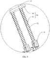
- the reset assembly 80 includes a spring 82 and a securing block 84, the securing block 84 is secured to the mounting plate 101, and installation space is provided between the securing block 84 and the second transmission assembly 30.
- the spring 82 is sleeved around a periphery of the transmission element 32 and is accommodated in the installation space. Reset is implemented by using a resilient force of the spring 82.
- the transmission element 32 resets under the action of a spring force and also drives the phase shifter 50 to work in a reverse direction.
- One part of the transmission element 32 for sleeving of the spring 82 and the other part of the transmission element 32 may be of an integrated structure.
- a guiding rod 321 may be secured to one end of the transmission element 32, and the spring 82 may be sleeved around a periphery of the guiding rod 321.
- the guiding rod 321 may be designed as a telescopic rod. A length of the guiding rod 321 can be adjusted, and an elastic force of the spring may be adjusted by adjusting the length of the guiding rod 321.
- One end of the spring 82 is secured to the securing block 84, and the other end of the spring 82 is secured to the second transmission assembly 40 or the transmission element 32. In the implementation example shown in FIG. 9 , the other end of the spring 82 is secured to the pull rod adapter 41 of the second transmission assembly 40. Because the transmission element 32 and the second transmission assembly 40 are synchronously moved, a reset function may also be implemented when the spring 82 is secured to the transmission element 32. In a process in which the transmission element 32 drives the second transmission assembly 40 to move in a straight line relative to the securing block 84, the spring 82 is compressed or stretched.
- the reset assembly 80 may be a reset mechanism in a rotation direction.
- the reset assembly 80 may include a torsional spring (instead of the spring, to implement a resilient force in the rotation direction) and a securing block 84.
- the securing block 84 is secured to the mounting plate 101.
- One end of the torsional spring is secured to the securing block 84, and the other end of the torsional spring is secured to the second transmission assembly 40 or the transmission element 32.
- the torsional spring is elastically deformed.
- the first transmission assembly 20 drives the transmission element 32 to rotate.
- the second transmission assembly 40 includes a worm and worm wheel assembly.
- a rotational motion of the transmission element 32 drives a rotational motion of a worm 42 of the second transmission assembly 40.
- the worm wheel 44 is driven to rotate through mating of the worm 42 and a worm wheel 44, and then the phase shifter 50 is driven to rotate and adjust the antenna downtilt.
- the transmission element 32 and the worm 42 may be secured by welding.
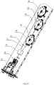
- the two phase shifters 50 may be connected in series to one end of a same transmission element 32.
- the two phase shifts 50 may be connected in series by using a flexible transmission element similar to the transmission element 32.
- each second transmission assembly 40 is connected between one transmission element 32 and one phase shifter 50, to form at least two transmission paths that are connected in parallel.
- a combiner module 70 is disposed between the at least two transmission elements 32 and the first transmission assembly 20, and the combiner module 70 is configured to implement conversion between the first transmission assembly 20 and the at least two transmission elements 32.
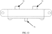
- the combiner module 70 includes one input shaft 71 and at least two output shafts 72.
- the input shaft 71 is connected to the first transmission assembly 20, and the at least two output shafts 72 are separately connected to the at least two transmission elements 32.
- a force between the input shaft 71 and the at least two output shafts 72 is transmitted by using a gear.
- an input gear 712 is disposed on the input shaft 71
- an output gear 722 is disposed on each output shaft 72
- conversion between the first transmission assembly 20 and the two transmission elements 32 is implemented through simultaneous meshing of the input gear 712 and the two output gears 722.
- a planetary carrier and a planetary gear may be disposed in the combiner module 70. Conversion between the first transmission assembly 20 and a plurality of transmission elements 32 may be implemented through mating of a plurality of planetary gears and a sun gear connected to the input shaft 71.
- the second transmission assembly 40 is a push and pull rod, and can translate in a straight line.
- a conversion assembly 46 is disposed between the second transmission assembly 40 and the transmission element 32.
- the first transmission assembly 20 drives the transmission element 32 to rotate, and the conversion assembly 46 converts a rotational motion of the transmission element 32 into a direct motion, to drive the second transmission assembly 40 to move in a straight line.
- the conversion assembly 46 includes a worm wheel 462, a worm 464, a gear 466, and a gear rack 468.
- the worm 464 is connected to the transmission element 32
- the gear rack 468 is connected to the second transmission assembly 40
- the worm wheel 462 shares a shaft with the gear 466.
- the transmission element 32 drives the worm 464 to rotate, drives the gear 466 to rotate through mating of the worm 464 and the worm wheel 462 and synchronous rotation of the worm wheel 462 and the gear 466, and drives the second transmission assembly 40 to move in a straight line through mating of the gear 466 and the gear rack 468.
- the transmission element 32 can be simultaneously connected to at least two second transmission assemblies 40.
- each second transmission assembly 40 drives one phase shifter 50.
Landscapes
- Engineering & Computer Science (AREA)
- Computer Networks & Wireless Communication (AREA)
- Signal Processing (AREA)
- Variable-Direction Aerials And Aerial Arrays (AREA)
Applications Claiming Priority (1)
| Application Number | Priority Date | Filing Date | Title |
|---|---|---|---|
| PCT/CN2017/078945 WO2018176361A1 (zh) | 2017-03-31 | 2017-03-31 | 天线下倾角调节装置及通信设备 |
Publications (3)
| Publication Number | Publication Date |
|---|---|
| EP3595084A1 true EP3595084A1 (de) | 2020-01-15 |
| EP3595084A4 EP3595084A4 (de) | 2020-03-18 |
| EP3595084B1 EP3595084B1 (de) | 2025-02-26 |
Family
ID=63673960
Family Applications (1)
| Application Number | Title | Priority Date | Filing Date |
|---|---|---|---|
| EP17902715.6A Active EP3595084B1 (de) | 2017-03-31 | 2017-03-31 | Justierungsvorrichtung für antennenabwärtsneigung und kommunikationsvorrichtung |
Country Status (4)
| Country | Link |
|---|---|
| US (1) | US10734712B2 (de) |
| EP (1) | EP3595084B1 (de) |
| CN (1) | CN110462927B (de) |
| WO (1) | WO2018176361A1 (de) |
Cited By (1)
| Publication number | Priority date | Publication date | Assignee | Title |
|---|---|---|---|---|
| CN114614258A (zh) * | 2022-02-16 | 2022-06-10 | 安徽荣骐电子信息有限公司 | 一种有源天线相位调整的线性执行装置及天线装置 |
Families Citing this family (14)
| Publication number | Priority date | Publication date | Assignee | Title |
|---|---|---|---|---|
| KR101899928B1 (ko) * | 2017-01-26 | 2018-09-18 | 주식회사 케이엠더블유 | 안테나 조립체 |
| CN108506448B (zh) * | 2017-12-06 | 2020-01-17 | 深圳市兆威机电股份有限公司 | 多频天线传动装置 |
| JP7337259B2 (ja) * | 2019-08-30 | 2023-09-01 | ケーエムダブリュ・インコーポレーテッド | アンテナ用クランピング装置 |
| US11600920B2 (en) * | 2019-12-13 | 2023-03-07 | Commscope Technologies Llc | Remote electronic tilt actuators for controlling multiple phase shifters and base station antennas with remote electronic tilt actuators |
| US11721897B2 (en) | 2019-12-13 | 2023-08-08 | Commscope Technologies Llc | Remote electronic tilt actuators for controlling multiple phase shifters and base station antennas with remote electronic tilt actuators |
| CN112072307B (zh) * | 2020-07-20 | 2022-12-23 | 中天通信技术有限公司 | 电调天线的下倾角调节装置及电调天线 |
| CN114390542B (zh) * | 2020-10-16 | 2024-04-19 | 中国移动通信集团设计院有限公司 | 无线网络优化装置及优化方法 |
| CN112367569B (zh) * | 2020-11-11 | 2023-05-09 | 国家电网有限公司客户服务中心 | 一种软硬融合的移动通信服务设备 |
| WO2022133653A1 (zh) * | 2020-12-21 | 2022-06-30 | 华为技术有限公司 | 天线控制装置、天线及基站 |
| CN112670716B (zh) * | 2020-12-29 | 2024-06-25 | 京信通信技术(广州)有限公司 | 一种天线和组合式天线系统 |
| CN112736464B (zh) * | 2020-12-30 | 2024-08-13 | 京信通信技术(广州)有限公司 | 基站天线及传动装置 |
| CN113013572B (zh) * | 2021-02-24 | 2022-10-04 | 国信军创(岳阳)六九零六科技有限公司 | 一种用于通讯设备上天线的装调机构 |
| CN113809876B (zh) * | 2021-10-27 | 2022-09-02 | 中国电子科技集团公司第三十八研究所 | 一种高精度分体式雷达伺服扫描器 |
| CN114824802A (zh) * | 2022-03-31 | 2022-07-29 | 京信通信技术(广州)有限公司 | 驱动机构与选频移相装置 |
Family Cites Families (21)
| Publication number | Priority date | Publication date | Assignee | Title |
|---|---|---|---|---|
| US6310585B1 (en) * | 1999-09-29 | 2001-10-30 | Radio Frequency Systems, Inc. | Isolation improvement mechanism for dual polarization scanning antennas |
| US20050003864A1 (en) * | 2003-07-03 | 2005-01-06 | Elliot Robert Douglas | Antenna system |
| KR101605860B1 (ko) * | 2009-05-12 | 2016-03-24 | 주식회사 에이스테크놀로지 | 안테나에 있어서 도브 테일 장치 |
| DE102010012991B4 (de) * | 2010-03-26 | 2011-12-15 | Kathrein-Werke Kg | Multi-Strahlformeinrichtung |
| CN102136630B (zh) * | 2010-11-23 | 2015-06-03 | 华为技术有限公司 | 天线装置、天线系统和天线电调方法 |
| DE102011009600B3 (de) * | 2011-01-27 | 2012-03-15 | Kathrein-Werke Kg | Mobilfunkantenne mit Multi-Strahlformeinrichtung |
| CN102171889B (zh) * | 2011-04-14 | 2014-12-24 | 华为技术有限公司 | 相位调整装置及多频天线 |
| WO2012126439A2 (zh) * | 2012-05-30 | 2012-09-27 | 华为技术有限公司 | 天线阵列、天线装置和基站 |
| DE102013009224A1 (de) * | 2013-05-31 | 2014-12-04 | Kathrein-Werke Kg | Modulare Verstelleinrichtung, insbesondere für HF-Geräte |
| CN103700944B (zh) * | 2013-12-31 | 2016-08-24 | 安徽省大富重工技术有限公司 | 一种天线及其电下倾角的调节装置 |
| CN104170165B (zh) * | 2014-02-10 | 2016-06-08 | 华为技术有限公司 | 天线调节装置和电调天线 |
| CN104090531B (zh) * | 2014-06-06 | 2017-01-04 | 西安华为技术有限公司 | 开关组件、开关组件控制方法、控制器及基站 |
| CN104577295B (zh) * | 2014-12-31 | 2018-11-06 | 安徽省大富重工技术有限公司 | 天线 |
| CN204537637U (zh) * | 2015-04-03 | 2015-08-05 | 京信通信技术(广州)有限公司 | 天线下倾角显示装置及天线 |
| WO2016205995A1 (zh) * | 2015-06-23 | 2016-12-29 | 华为技术有限公司 | 移相器和天线 |
| CN107925143B (zh) * | 2015-08-31 | 2019-12-24 | 华为技术有限公司 | 移相器、天线和基站 |
| DE202015105535U1 (de) * | 2015-10-19 | 2015-11-27 | Kathrein Werke Kg | Verstellelement zur Verwendung in Mobilfunkantennen und Mobilfunkantenne mit Verstellelement |
| CN109075442A (zh) * | 2016-05-04 | 2018-12-21 | 康普技术有限责任公司 | 调节天线塔上的天线波束的系统和方法 |
| CN106159441B (zh) * | 2016-08-04 | 2021-08-20 | 京信通信技术(广州)有限公司 | 角度指示器、下倾角显示装置及天线 |
| WO2018140305A1 (en) * | 2017-01-24 | 2018-08-02 | Commscope Technologies Llc | Base station antennas including supplemental arrays |
| CN110401036A (zh) * | 2018-04-24 | 2019-11-01 | 康普技术有限责任公司 | 用于基站天线的联动机构 |
-
2017
- 2017-03-31 WO PCT/CN2017/078945 patent/WO2018176361A1/zh not_active Ceased
- 2017-03-31 CN CN201780088968.6A patent/CN110462927B/zh active Active
- 2017-03-31 EP EP17902715.6A patent/EP3595084B1/de active Active
-
2019
- 2019-09-27 US US16/584,951 patent/US10734712B2/en active Active
Cited By (1)
| Publication number | Priority date | Publication date | Assignee | Title |
|---|---|---|---|---|
| CN114614258A (zh) * | 2022-02-16 | 2022-06-10 | 安徽荣骐电子信息有限公司 | 一种有源天线相位调整的线性执行装置及天线装置 |
Also Published As
| Publication number | Publication date |
|---|---|
| WO2018176361A1 (zh) | 2018-10-04 |
| CN110462927A (zh) | 2019-11-15 |
| EP3595084B1 (de) | 2025-02-26 |
| US20200028245A1 (en) | 2020-01-23 |
| US10734712B2 (en) | 2020-08-04 |
| EP3595084A4 (de) | 2020-03-18 |
| CN110462927B (zh) | 2021-09-14 |
Similar Documents
| Publication | Publication Date | Title |
|---|---|---|
| US10734712B2 (en) | Antenna downtilt adjustment apparatus and communications device | |
| CN102447163B (zh) | 一种宽频带双极化全向天线及馈电方法 | |
| US20240313427A1 (en) | Antenna and communication system | |
| EP2937935A2 (de) | Vorrichtung zur verringerung der interferenz zwischen antennen mehrerer basisstationen | |
| WO2023051471A1 (zh) | 一种天线系统及基站天馈系统 | |
| US20240313430A1 (en) | Antenna system and base station antenna feeder system | |
| CN116266664B (zh) | 一种天线系统和通信设备 | |
| CN114050399B (zh) | 基站天线 | |
| CN108432040A (zh) | 包含波束成形装置的天线 | |
| CN219123480U (zh) | 天线和基站 | |
| CN112736464B (zh) | 基站天线及传动装置 | |
| WO2023174196A1 (zh) | 一种通信装置及基站天馈系统 | |
| CN115911822A (zh) | 一种天线及基站天馈系统 | |
| JP2016208158A (ja) | 無線基地局構造 | |
| WO2026092522A1 (zh) | 天线、通信设备和通信系统 | |
| WO2026092419A1 (zh) | 一种天线、通信设备和通信系统 | |
| WO2026036932A1 (zh) | 一种天线、通信设备和通信系统 | |
| CN224260850U (zh) | 一种多路移相器用小型换挡式驱动传动装置 | |
| CN115939731B (zh) | 天线结构及无线传输装置 | |
| CN120637824A (zh) | 一种移相器、馈电器件、天线以及通信设备 | |
| CN214542507U (zh) | 一种5g通讯天线的共用安装支架 | |
| WO2026081485A1 (zh) | 一种调控装置、馈电网络、天线及通信设备 | |
| CN210326092U (zh) | 一种2.4g铜管天线安装结构 | |
| WO2024125427A1 (zh) | 基站天线以及基站 | |
| WO2026036942A1 (zh) | 一种天线、通信设备和通信系统 |
Legal Events
| Date | Code | Title | Description |
|---|---|---|---|
| STAA | Information on the status of an ep patent application or granted ep patent |
Free format text: STATUS: THE INTERNATIONAL PUBLICATION HAS BEEN MADE |
|
| PUAI | Public reference made under article 153(3) epc to a published international application that has entered the european phase |
Free format text: ORIGINAL CODE: 0009012 |
|
| STAA | Information on the status of an ep patent application or granted ep patent |
Free format text: STATUS: REQUEST FOR EXAMINATION WAS MADE |
|
| 17P | Request for examination filed |
Effective date: 20191008 |
|
| AK | Designated contracting states |
Kind code of ref document: A1 Designated state(s): AL AT BE BG CH CY CZ DE DK EE ES FI FR GB GR HR HU IE IS IT LI LT LU LV MC MK MT NL NO PL PT RO RS SE SI SK SM TR |
|
| AX | Request for extension of the european patent |
Extension state: BA ME |
|
| A4 | Supplementary search report drawn up and despatched |
Effective date: 20200219 |
|
| RIC1 | Information provided on ipc code assigned before grant |
Ipc: H01Q 19/10 20060101ALN20200213BHEP Ipc: H01Q 3/32 20060101ALI20200213BHEP Ipc: H01Q 1/24 20060101AFI20200213BHEP |
|
| DAV | Request for validation of the european patent (deleted) | ||
| DAX | Request for extension of the european patent (deleted) | ||
| STAA | Information on the status of an ep patent application or granted ep patent |
Free format text: STATUS: EXAMINATION IS IN PROGRESS |
|
| 17Q | First examination report despatched |
Effective date: 20210922 |
|
| GRAP | Despatch of communication of intention to grant a patent |
Free format text: ORIGINAL CODE: EPIDOSNIGR1 |
|
| STAA | Information on the status of an ep patent application or granted ep patent |
Free format text: STATUS: GRANT OF PATENT IS INTENDED |
|
| RIC1 | Information provided on ipc code assigned before grant |
Ipc: H01Q 19/10 20060101ALN20240905BHEP Ipc: H01Q 3/32 20060101ALI20240905BHEP Ipc: H01Q 1/24 20060101AFI20240905BHEP |
|
| INTG | Intention to grant announced |
Effective date: 20241002 |
|
| GRAS | Grant fee paid |
Free format text: ORIGINAL CODE: EPIDOSNIGR3 |
|
| GRAA | (expected) grant |
Free format text: ORIGINAL CODE: 0009210 |
|
| STAA | Information on the status of an ep patent application or granted ep patent |
Free format text: STATUS: THE PATENT HAS BEEN GRANTED |
|
| AK | Designated contracting states |
Kind code of ref document: B1 Designated state(s): AL AT BE BG CH CY CZ DE DK EE ES FI FR GB GR HR HU IE IS IT LI LT LU LV MC MK MT NL NO PL PT RO RS SE SI SK SM TR |
|
| REG | Reference to a national code |
Ref country code: GB Ref legal event code: FG4D |
|
| REG | Reference to a national code |
Ref country code: CH Ref legal event code: EP |
|
| REG | Reference to a national code |
Ref country code: DE Ref legal event code: R096 Ref document number: 602017088075 Country of ref document: DE |
|
| REG | Reference to a national code |
Ref country code: IE Ref legal event code: FG4D |
|
| REG | Reference to a national code |
Ref country code: NL Ref legal event code: MP Effective date: 20250226 |
|
| PG25 | Lapsed in a contracting state [announced via postgrant information from national office to epo] |
Ref country code: RS Free format text: LAPSE BECAUSE OF FAILURE TO SUBMIT A TRANSLATION OF THE DESCRIPTION OR TO PAY THE FEE WITHIN THE PRESCRIBED TIME-LIMIT Effective date: 20250526 |
|
| PG25 | Lapsed in a contracting state [announced via postgrant information from national office to epo] |
Ref country code: FI Free format text: LAPSE BECAUSE OF FAILURE TO SUBMIT A TRANSLATION OF THE DESCRIPTION OR TO PAY THE FEE WITHIN THE PRESCRIBED TIME-LIMIT Effective date: 20250226 |
|
| PG25 | Lapsed in a contracting state [announced via postgrant information from national office to epo] |
Ref country code: PL Free format text: LAPSE BECAUSE OF FAILURE TO SUBMIT A TRANSLATION OF THE DESCRIPTION OR TO PAY THE FEE WITHIN THE PRESCRIBED TIME-LIMIT Effective date: 20250226 |
|
| PG25 | Lapsed in a contracting state [announced via postgrant information from national office to epo] |
Ref country code: ES Free format text: LAPSE BECAUSE OF FAILURE TO SUBMIT A TRANSLATION OF THE DESCRIPTION OR TO PAY THE FEE WITHIN THE PRESCRIBED TIME-LIMIT Effective date: 20250226 |
|
| REG | Reference to a national code |
Ref country code: LT Ref legal event code: MG9D |
|
| PG25 | Lapsed in a contracting state [announced via postgrant information from national office to epo] |
Ref country code: NO Free format text: LAPSE BECAUSE OF FAILURE TO SUBMIT A TRANSLATION OF THE DESCRIPTION OR TO PAY THE FEE WITHIN THE PRESCRIBED TIME-LIMIT Effective date: 20250526 Ref country code: IS Free format text: LAPSE BECAUSE OF FAILURE TO SUBMIT A TRANSLATION OF THE DESCRIPTION OR TO PAY THE FEE WITHIN THE PRESCRIBED TIME-LIMIT Effective date: 20250626 |
|
| PG25 | Lapsed in a contracting state [announced via postgrant information from national office to epo] |
Ref country code: NL Free format text: LAPSE BECAUSE OF FAILURE TO SUBMIT A TRANSLATION OF THE DESCRIPTION OR TO PAY THE FEE WITHIN THE PRESCRIBED TIME-LIMIT Effective date: 20250226 |
|
| PG25 | Lapsed in a contracting state [announced via postgrant information from national office to epo] |
Ref country code: HR Free format text: LAPSE BECAUSE OF FAILURE TO SUBMIT A TRANSLATION OF THE DESCRIPTION OR TO PAY THE FEE WITHIN THE PRESCRIBED TIME-LIMIT Effective date: 20250226 |
|
| PG25 | Lapsed in a contracting state [announced via postgrant information from national office to epo] |
Ref country code: LV Free format text: LAPSE BECAUSE OF FAILURE TO SUBMIT A TRANSLATION OF THE DESCRIPTION OR TO PAY THE FEE WITHIN THE PRESCRIBED TIME-LIMIT Effective date: 20250226 Ref country code: PT Free format text: LAPSE BECAUSE OF FAILURE TO SUBMIT A TRANSLATION OF THE DESCRIPTION OR TO PAY THE FEE WITHIN THE PRESCRIBED TIME-LIMIT Effective date: 20250626 |
|
| PG25 | Lapsed in a contracting state [announced via postgrant information from national office to epo] |
Ref country code: GR Free format text: LAPSE BECAUSE OF FAILURE TO SUBMIT A TRANSLATION OF THE DESCRIPTION OR TO PAY THE FEE WITHIN THE PRESCRIBED TIME-LIMIT Effective date: 20250527 Ref country code: BG Free format text: LAPSE BECAUSE OF FAILURE TO SUBMIT A TRANSLATION OF THE DESCRIPTION OR TO PAY THE FEE WITHIN THE PRESCRIBED TIME-LIMIT Effective date: 20250226 |
|
| REG | Reference to a national code |
Ref country code: AT Ref legal event code: MK05 Ref document number: 1771612 Country of ref document: AT Kind code of ref document: T Effective date: 20250226 |
|
| PG25 | Lapsed in a contracting state [announced via postgrant information from national office to epo] |
Ref country code: SE Free format text: LAPSE BECAUSE OF FAILURE TO SUBMIT A TRANSLATION OF THE DESCRIPTION OR TO PAY THE FEE WITHIN THE PRESCRIBED TIME-LIMIT Effective date: 20250226 |
|
| PG25 | Lapsed in a contracting state [announced via postgrant information from national office to epo] |
Ref country code: SM Free format text: LAPSE BECAUSE OF FAILURE TO SUBMIT A TRANSLATION OF THE DESCRIPTION OR TO PAY THE FEE WITHIN THE PRESCRIBED TIME-LIMIT Effective date: 20250226 |
|
| PG25 | Lapsed in a contracting state [announced via postgrant information from national office to epo] |
Ref country code: DK Free format text: LAPSE BECAUSE OF FAILURE TO SUBMIT A TRANSLATION OF THE DESCRIPTION OR TO PAY THE FEE WITHIN THE PRESCRIBED TIME-LIMIT Effective date: 20250226 |
|
| PG25 | Lapsed in a contracting state [announced via postgrant information from national office to epo] |
Ref country code: IT Free format text: LAPSE BECAUSE OF FAILURE TO SUBMIT A TRANSLATION OF THE DESCRIPTION OR TO PAY THE FEE WITHIN THE PRESCRIBED TIME-LIMIT Effective date: 20250226 |
|
| PG25 | Lapsed in a contracting state [announced via postgrant information from national office to epo] |
Ref country code: AT Free format text: LAPSE BECAUSE OF FAILURE TO SUBMIT A TRANSLATION OF THE DESCRIPTION OR TO PAY THE FEE WITHIN THE PRESCRIBED TIME-LIMIT Effective date: 20250226 |
|
| PG25 | Lapsed in a contracting state [announced via postgrant information from national office to epo] |
Ref country code: EE Free format text: LAPSE BECAUSE OF FAILURE TO SUBMIT A TRANSLATION OF THE DESCRIPTION OR TO PAY THE FEE WITHIN THE PRESCRIBED TIME-LIMIT Effective date: 20250226 Ref country code: CZ Free format text: LAPSE BECAUSE OF FAILURE TO SUBMIT A TRANSLATION OF THE DESCRIPTION OR TO PAY THE FEE WITHIN THE PRESCRIBED TIME-LIMIT Effective date: 20250226 |
|
| REG | Reference to a national code |
Ref country code: CH Ref legal event code: H13 Free format text: ST27 STATUS EVENT CODE: U-0-0-H10-H13 (AS PROVIDED BY THE NATIONAL OFFICE) Effective date: 20251023 |
|
| PG25 | Lapsed in a contracting state [announced via postgrant information from national office to epo] |
Ref country code: RO Free format text: LAPSE BECAUSE OF FAILURE TO SUBMIT A TRANSLATION OF THE DESCRIPTION OR TO PAY THE FEE WITHIN THE PRESCRIBED TIME-LIMIT Effective date: 20250226 |
|
| PG25 | Lapsed in a contracting state [announced via postgrant information from national office to epo] |
Ref country code: SK Free format text: LAPSE BECAUSE OF FAILURE TO SUBMIT A TRANSLATION OF THE DESCRIPTION OR TO PAY THE FEE WITHIN THE PRESCRIBED TIME-LIMIT Effective date: 20250226 |
|
| PG25 | Lapsed in a contracting state [announced via postgrant information from national office to epo] |
Ref country code: LU Free format text: LAPSE BECAUSE OF NON-PAYMENT OF DUE FEES Effective date: 20250331 |
|
| REG | Reference to a national code |
Ref country code: DE Ref legal event code: R097 Ref document number: 602017088075 Country of ref document: DE |
|
| REG | Reference to a national code |
Ref country code: BE Ref legal event code: MM Effective date: 20250331 |
|
| PG25 | Lapsed in a contracting state [announced via postgrant information from national office to epo] |
Ref country code: MC Free format text: LAPSE BECAUSE OF FAILURE TO SUBMIT A TRANSLATION OF THE DESCRIPTION OR TO PAY THE FEE WITHIN THE PRESCRIBED TIME-LIMIT Effective date: 20250226 |
|
| PLBE | No opposition filed within time limit |
Free format text: ORIGINAL CODE: 0009261 |
|
| STAA | Information on the status of an ep patent application or granted ep patent |
Free format text: STATUS: NO OPPOSITION FILED WITHIN TIME LIMIT |
|
| PG25 | Lapsed in a contracting state [announced via postgrant information from national office to epo] |
Ref country code: FR Free format text: LAPSE BECAUSE OF NON-PAYMENT OF DUE FEES Effective date: 20250426 |
|
| PG25 | Lapsed in a contracting state [announced via postgrant information from national office to epo] |
Ref country code: BE Free format text: LAPSE BECAUSE OF NON-PAYMENT OF DUE FEES Effective date: 20250331 |
|
| PG25 | Lapsed in a contracting state [announced via postgrant information from national office to epo] |
Ref country code: CH Free format text: LAPSE BECAUSE OF NON-PAYMENT OF DUE FEES Effective date: 20250331 |
|
| PG25 | Lapsed in a contracting state [announced via postgrant information from national office to epo] |
Ref country code: IE Free format text: LAPSE BECAUSE OF NON-PAYMENT OF DUE FEES Effective date: 20250331 |
|
| GBPC | Gb: european patent ceased through non-payment of renewal fee |
Effective date: 20250526 |
|
| 26N | No opposition filed |
Effective date: 20251127 |
|
| PG25 | Lapsed in a contracting state [announced via postgrant information from national office to epo] |
Ref country code: GB Free format text: LAPSE BECAUSE OF NON-PAYMENT OF DUE FEES Effective date: 20250526 |
|
| PGFP | Annual fee paid to national office [announced via postgrant information from national office to epo] |
Ref country code: DE Payment date: 20260204 Year of fee payment: 10 |