EP2937935A2 - Vorrichtung zur verringerung der interferenz zwischen antennen mehrerer basisstationen - Google Patents
Vorrichtung zur verringerung der interferenz zwischen antennen mehrerer basisstationen Download PDFInfo
- Publication number
- EP2937935A2 EP2937935A2 EP13807710.2A EP13807710A EP2937935A2 EP 2937935 A2 EP2937935 A2 EP 2937935A2 EP 13807710 A EP13807710 A EP 13807710A EP 2937935 A2 EP2937935 A2 EP 2937935A2
- Authority
- EP
- European Patent Office
- Prior art keywords
- shielding plate
- bracket
- antennas
- shielding
- holding pole
- Prior art date
- Legal status (The legal status is an assumption and is not a legal conclusion. Google has not performed a legal analysis and makes no representation as to the accuracy of the status listed.)
- Withdrawn
Links
Images


Classifications
-
- H—ELECTRICITY
- H01—ELECTRIC ELEMENTS
- H01Q—ANTENNAS, i.e. RADIO AERIALS
- H01Q1/00—Details of, or arrangements associated with, antennas
- H01Q1/52—Means for reducing coupling between antennas; Means for reducing coupling between an antenna and another structure
- H01Q1/526—Electromagnetic shields
-
- H—ELECTRICITY
- H01—ELECTRIC ELEMENTS
- H01Q—ANTENNAS, i.e. RADIO AERIALS
- H01Q1/00—Details of, or arrangements associated with, antennas
- H01Q1/12—Supports; Mounting means
- H01Q1/22—Supports; Mounting means by structural association with other equipment or articles
- H01Q1/24—Supports; Mounting means by structural association with other equipment or articles with receiving set
- H01Q1/241—Supports; Mounting means by structural association with other equipment or articles with receiving set used in mobile communications, e.g. GSM
- H01Q1/246—Supports; Mounting means by structural association with other equipment or articles with receiving set used in mobile communications, e.g. GSM specially adapted for base stations
-
- H—ELECTRICITY
- H01—ELECTRIC ELEMENTS
- H01Q—ANTENNAS, i.e. RADIO AERIALS
- H01Q1/00—Details of, or arrangements associated with, antennas
- H01Q1/12—Supports; Mounting means
- H01Q1/1242—Rigid masts specially adapted for supporting an aerial
-
- H—ELECTRICITY
- H01—ELECTRIC ELEMENTS
- H01Q—ANTENNAS, i.e. RADIO AERIALS
- H01Q1/00—Details of, or arrangements associated with, antennas
- H01Q1/52—Means for reducing coupling between antennas; Means for reducing coupling between an antenna and another structure
- H01Q1/521—Means for reducing coupling between antennas; Means for reducing coupling between an antenna and another structure reducing the coupling between adjacent antennas
-
- H—ELECTRICITY
- H01—ELECTRIC ELEMENTS
- H01Q—ANTENNAS, i.e. RADIO AERIALS
- H01Q17/00—Devices for absorbing waves radiated from an antenna; Combinations of such devices with active antenna elements or systems
Definitions
- the present disclosure relates to the antenna technology of a base station in the field of mobile communications, and in particular to a device for reducing interference among antennas of multiple base stations.
- the same base station may have antennas of a plurality of communications systems. Due to restriction to geological locations, distances among some antennas are very small, leading to isolation reduction among antennas, giving a plurality of wireless signals a chance to simultaneously enter into a receiver, thus causing severe interferences to available signals. Therefore, improving isolations among antennas from different systems to enhance anti-interference capabilities has significantly crucial meanings to the communications system.
- Chinese patent ( CN201010276357 ) describes an anti-interference wide-beam WLAN base station antenna, including a metal reflector, a microstrip plate fixed on the metal reflector through an insulating shore, and a radiate array antenna laid on the microstrip plate.
- the radiate array antenna includes a set of microstrip transmission lines laid on the back of the microstrip plate and a plurality of radiation units laid on the front of the microstrip plate and arranged in columns.
- the antenna involves a simple manufacture technology, has a light structure, needs a low cost, and is easy to be put into large-scale industrial production and broadened in the aspect of beam-width in the horizontal plane, as well as solves the interference problem between the same polarization when current available antennas of a vertically polarized kind are used in practice.
- the patent increases anti-interference to the design of the antenna per se, mainly aiming at the interference problem the same polarization of antennas of vertically polarized kind.
- the Chinese patent discloses an apparatus for absorbing and shielding electromagnetic waves of a mobile phone antenna, including a half-shielding apparatus on an antenna body, wherein the apparatus mainly includes at least one small absorbing slice and a spacer which can efficiently shield electromagnetic waves directed to a user.
- An inner diameter of the spacer is not greater than an outer diameter of the antenna.
- the spacer is a metal slice or an absorbing material.
- the absorbing slice is connected to or embedded in the spacer. Outside the spacer there is a housing.
- the implementation process of the patent impacts a radiation pattern.
- the cell phone antenna is an omni-directional antenna. By shielding radiation signals radiated to a brain direction, the patent mostly lowers a detriment to a human body from the electromagnetic waves.
- the patent has greatly changed a main beam pattern per se, thus not being suitable to handle interferences among antennas of multiple base stations.
- the present disclosure is intended to provide a device for reducing interference among antennas of multiple base stations, which can efficiently increase isolation among the antennas of the multiple base stations, thus reducing interferences among antennas of base stations.
- the present disclosure provides a device for reducing interference among antennas of multiple base stations, which includes: an antenna module placed on a base station, and configured to transmit and receive radio waves; a holding pole placed on the base station, and configured to support the antenna module; a mounting bracket, coupled to the antenna module and the holding pole; and a shielding apparatus, placed on the holding pole or the antenna module, and capable of being adjusted in directions.
- the shielding apparatus may be an apparatus that absorbs or shields an electromagnetic wave.
- the shielding apparatus may include: a stretchable shielding plate; a first bracket coupled to the holding pole, wherein the first bracket is capable of sliding along an exterior of the holding pole; and a rotation shaft placed on the shielding plate, wherein the rotation shaft is hinged to the first bracket.
- the shielding plate may be composed of a plurality of reticular plates, and adjacent reticular plates uses sliding connection, and one of the plurality of the reticular plates is fixedly coupled with the rotation shaft.
- the shielding plate may be a folded plate which has an adjustable length.
- the shielding apparatus may include: a stretchable shielding plate; a second bracket placed on the antenna module; and a connection sleeve placed on the shielding plate, wherein the connection sleeve is rotationally coupled to the second bracket.
- the shielding plate may be a folded plate which has an adjustable length.
- the shielding plate may be made of a metal material or an absorbing material.
- a length of the shielding plate may be 50% ⁇ 80% of a length of a radome.
- the first bracket may be a stretchable bracket, and one end of the first bracket is equipped with a fixed sleeve placed on the holding pole.
- the device for reducing interference among antennas of multiple base stations provided by the embodiments, according to the present disclosure, at least possesses following advantages:
- a device for reducing interference among antennas of multiple base stations includes: an antenna module 1 placed on a base station, and configured to transmit and receive radio waves; a holding pole 2 placed on the base station, and configured to support the antenna module; a mounting bracket 3, coupled to the antenna module and the holding pole; and a shielding apparatus placed on the holding pole or the antenna module, and capable of being adjusted in directions.
- the present disclosure employs the shielding apparatus among the antennas of the multiple base stations to increase isolation and reduce interferences among antennas of the base stations.
- the device for increasing isolation among the antennas of the base stations includes the antenna module, the mounting bracket, the holding pole and the shielding apparatus.
- the antenna module uses the antenna module in the prior art, which is placed on the base station and consists of a reflection plate, a matched network, an antenna unit, and a connector, which are placed within a radome, and the radome, thus implementing the transmission and reception of the radio waves.
- the cylindrical holding pole is also placed on the base station, where a symmetry axis of which coincides with a z-axis.
- the antenna module is placed on the holding pole through the mounting bracket, forming a support to the antenna module.
- the shielding apparatus with functions of absorbing or shielding an electromagnetic wave can be placed either on the holding pole or on the antenna module.
- a spatial position of the shielding apparatus can be adjusted for the purpose of hindering an unnecessary signal of a frequency band and of directly connecting to a required signal of a frequency band, thus acquiring an optimal tuning position.
- the shielding apparatus according to the present disclosure may be placed either on the holding pole or the antenna module, further description for the structure of the shielding apparatus placed either on the holding pole or the antenna module is given in combination with the specific embodiments hereinafter.
- a longitudinal direction involved in the present disclosure is the z-axis direction shown in Fig. 1 , 3 or 5
- a horizontal direction involved is a y-axis or an x-axis direction shown in Fig. 1 , 3 and 5 . Refer to each embodiment for specific description.
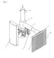
- Fig. 1 or 2 is a structural diagram of a device for reducing interference among antennas of multiple base stations according to the present disclosure, in which the shielding apparatus is placed on the holding pole.
- the shielding apparatus includes: a stretchable shielding plate 19; a first bracket 5 coupled to the holding pole 2, wherein the first bracket may slide along an exterior of the holding pole; and a rotation shaft 6 placed on the shielding plate, wherein the rotation shaft is hinged to the first bracket.
- the first bracket is stretchable along the y-axis.
- it is made of an insulation material.
- One end of the first bracket is fixedly provided with a fixed sleeve 4, and the fixed sleeve is placed on the exterior of the holding pole of a cylindrical shape, as a result, the first bracket may horizontally slide up and down along the exterior of the holding pole, further adjusting the height of the shielding plate for the purpose of acquiring an optimal tuning position.
- the other end of the first bracket is provided with a spherical groove, where the rotation shaft of the spherical groove is placed in a rotation manner inside the groove of the first bracket, as a result, the rotation shaft may rotate horizontally and almost 360° in pitch angle inside the groove, thus bringing along a corresponding rotation of the shielding plate being fixed to it so that the shielding plate acquires the optimal spatial-tuning position.
- the relative position of the first bracket and the radome may be determined according to real application scenarios.
- the shielding plate is composed of two reticular plates according to the present disclosure.
- the two reticular plates include a forward shielding plate 7 and a backward shielding plate 8.
- the forward shielding plate 7 and the backward shielding plate 8 are overlapped with each other vertically and use sliding connection therebetween. Therefore, it is possible to make the two reticular plates stretch out horizontally along the x-axis in a push-and-pull manner in accordance with applications in site.
- a horizontal distance in the push-and-pull is finely tuned on the premise that a main beam pattern of the antennas of the base station will not be influenced and the isolations among the base stations will be optimally improved.
- the backward shielding plate 8 or the forward shielding plate 7 is fixedly coupled with the rotation shaft using a sticky substance, or is fixedly coupled with the rotation shaft in other manners, as long as the manner in use can achieve reinforcement, windproof and prevention of ineffectiveness of the shielding apparatus due to execution of external forces.
- the shielding plate can rotate together with the rotation shaft, thus, the shielding plate can acquire the optimal tuning position.
- the rotation shaft is locked using a fastener. Therefore, the rotation shaft cannot continue rotations inside the groove of the first bracket, efficiently preventing looseness.
- the forward shielding plate 7 and the backward shielding plate 8 are shielding plates with a feature of frequency selection, which are made of a metal material with a feature of shielding electromagnetic waves, or are made of an absorbing material with a feature of absorbing electromagnetic waves.
- Mesh sizes of the forward shielding plate 7 and the backward shielding plate 8 vary with the frequency bands.
- a shape of a mesh may be one or many of a square, a circle or any other geometric shapes.
- a length of the shielding plate is 50% ⁇ 80% of a length of the radome.
- the length of the shielding plate is 67% of the length of the radome.
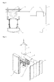
- Fig. 3 or 4 is a structural diagram of a device for reducing interference among antennas of multiple base stations according to the present disclosure, in which the shielding apparatus is placed on the holding pole.
- the shielding apparatus further includes: a stretchable shielding plate 19; a first bracket 5 coupled to the holding pole 2, wherein the first bracket is capable of sliding along an exterior of the holding pole; and a rotation shaft 6 placed on the shielding plate, wherein the rotation shaft is hinged to the first bracket.
- the structure of the shielding plate in the shielding apparatus varies from that in embodiment one, whereas structures of other components are all the same as those in embodiment one. Therefore, merely a description for the structure of the shielding plate is disclosed herein, whereas other structures shall not be described again.
- the shielding plate 19 is a folded plate along the x-axis, which has an adjustable length. It is possible to fine-tune its size in view of requirements, meanwhile the size in fine-tuning is subject to a premise that a main propagation direction of signals will not be influenced.
- the shielding plate may further be a shielding plate with a feature of frequency selection, which is made of a metal material with a feature of shielding electromagnetic waves, or is made of an absorbing material with a feature of absorbing electromagnetic waves.
- the shielding plate is fixedly coupled with the rotation shaft in an adhesive manner or any other manners.
- a length of the shielding plate is 50% ⁇ 80% of a length of the radome.
- the length of the shielding plate is 67% of the length of the radome.
- Fig. 5-7 are structural diagrams of a device for reducing interference among antennas of multiple base stations according to the present disclosure, in which the shielding apparatus is placed on the holding pole.
- the shielding apparatus further includes: a stretchable shielding plate 19; a second bracket 20 placed on the antenna module 1; and a connection sleeve 21 placed on the shielding plate, where the connection sleeve 21 is rotationally coupled to the second bracket.
- the second bracket is placed on one side of the radome in the antenna module, and the second bracket is detachably coupled to the radome. It is possible to determine a relative position between the second bracket and the radome in accordance with usage in site.
- the second bracket is a cylindrical shaft body that is made of an insulation material. A symmetric axis of the second bracket is in parallel with that of the holding pole.
- the connection sleeve is placed on the cylindrical shaft body and it can rotate around the cylindrical shaft body within the horizontal plane, thereby bringing along a fine-tuning with the shielding plate being fixedly coupled with it at a horizontal azimuth angle.
- the shielding plate 19 is a folded plate along the x-axis, whose transverse length is adjustable. It is possible to finely tune its size in view of requirements, meanwhile the size in fine-tuning is subject to a premise of not influencing a radiation pattern of the base station and optimally improving isolations among the antennas of the base stations.
- the shielding plate may be a shielding plate with a feature of frequency selection, which is made of a metal material with a feature of shielding electromagnetic waves, or is made of an absorbing material with a feature of absorbing electromagnetic waves.
- a length of the shielding plate is 50% ⁇ 80% of a length of the radome.
- the length of the shielding plate is 67% of the length of the radome.
- the shielding plate is fixedly coupled with the connection sleeve 21 in an adhesive manner using a sticky substance, or is fixedly coupled with the connection sleeve in other manners, as long as the manner in use can achieve reinforcement, windproof and prevention of ineffectiveness of the shielding apparatus due to execution of external forces.
- the shielding plate can rotate around the cylindrical shaft body with the connection sleeve within the horizontal plane, thus acquiring an optimal tuning position.
- the shielding plate may consist of the two reticular plates (not shown in Fig. 5-7 ) according to embodiment one. What differs is that, the forward shielding plate 7 and the backward shielding plate 8 in the two reticular plates are overlapped with each other horizontally along the x-axis. It is possible to stretch the two reticular plates out horizontally in a push-and-pull manner in accordance with applications in site. In addition, when the two reticular plates are stretched out, a horizontal distance in the push-and-pull is finely tuned subject to a premise of not influencing a main beam pattern of the antennas of the base station and optimally improving isolations among the base stations.
- the backward shielding plate 8 or the forward shielding plate 7 is fixedly connected with the connection sleeve in an adhesive manner using a sticky substance, or is fixedly connected with the connection sleeve in other manners, as long as the manner in use can achieve reinforcement, windproof and prevention of ineffectiveness of the shielding apparatus due to execution of external forces.
- the shielding plates can rotate together with the connection sleeve around the cylindrical shaft body, thus acquiring an optimal tuning position.
- the forward shielding plate 7 and the backward shielding plate 8 may also be shielding plates with a feature of frequency selection, which are made of a metal material with a feature of shielding the electromagnetic waves, or are made of an absorbing material with a feature of absorbing the electromagnetic waves.
- Mesh sizes of the forward shielding plate 7 and the backward shielding plate 8 vary with the frequency bands.
- a shape of a mesh may be one or many of a square, a circle or any other geometric shapes.
- a length of the shielding plate is 50% ⁇ 80% of a length of the radome.
- the length of the shielding plate is 67% of the length of the radome.
- a device for reducing interference among antennas of multiple base stations includes: an antenna module placed on a base station, and configured to transmit and receive radio waves; a holding pole placed on the base station, and configured to support the antenna module; a mounting bracket, coupled to the antenna module and the holding pole; and a shielding apparatus placed on the holding pole or the antenna module, and capable of being adjusted in directions.
- the structure of the device for reducing interference among antennas of multiple base stations provided by the present disclosure is simple; it is easy to manufacture and install the device; it can be applied to the base station's antennas in network use.
- the device for reducing interference among antennas of multiple base stations can efficiently increase isolation among the antennas of the multiple base stations and reduce interferences among antennas of base stations.
Landscapes
- Engineering & Computer Science (AREA)
- Computer Networks & Wireless Communication (AREA)
- Physics & Mathematics (AREA)
- Electromagnetism (AREA)
- Details Of Aerials (AREA)
- Aerials With Secondary Devices (AREA)
- Near-Field Transmission Systems (AREA)
Applications Claiming Priority (2)
| Application Number | Priority Date | Filing Date | Title |
|---|---|---|---|
| CN201320052615.XU CN203434278U (zh) | 2013-01-30 | 2013-01-30 | 减少多个基站天线间干扰的装置 |
| PCT/CN2013/082586 WO2013189454A2 (zh) | 2013-01-30 | 2013-08-29 | 减少多个基站天线间干扰的装置 |
Publications (2)
| Publication Number | Publication Date |
|---|---|
| EP2937935A2 true EP2937935A2 (de) | 2015-10-28 |
| EP2937935A4 EP2937935A4 (de) | 2016-01-20 |
Family
ID=49769592
Family Applications (1)
| Application Number | Title | Priority Date | Filing Date |
|---|---|---|---|
| EP13807710.2A Withdrawn EP2937935A4 (de) | 2013-01-30 | 2013-08-29 | Vorrichtung zur verringerung der interferenz zwischen antennen mehrerer basisstationen |
Country Status (4)
| Country | Link |
|---|---|
| US (1) | US9570801B2 (de) |
| EP (1) | EP2937935A4 (de) |
| CN (1) | CN203434278U (de) |
| WO (1) | WO2013189454A2 (de) |
Cited By (1)
| Publication number | Priority date | Publication date | Assignee | Title |
|---|---|---|---|---|
| CN110094097A (zh) * | 2019-03-26 | 2019-08-06 | 马鞍山圣德力智能科技有限公司 | 一种具有遮风挡雨功能的通讯铁塔 |
Families Citing this family (22)
| Publication number | Priority date | Publication date | Assignee | Title |
|---|---|---|---|---|
| CN104134867A (zh) * | 2014-08-19 | 2014-11-05 | 江苏中寰卫星导航通信有限公司 | 一种可调信号强度的天线 |
| US9553350B2 (en) * | 2015-05-14 | 2017-01-24 | Micro Wireless Solutions, Corp. | Antenna mount assembly |
| US9935364B2 (en) * | 2015-06-08 | 2018-04-03 | Parallel Wireless, Inc. | Single-radome multi-antenna assembly |
| EP3427558B1 (de) * | 2016-03-08 | 2022-06-29 | Commscope Technologies LLC | Universelle montageanordnung für entfernte funkeinheit (rru) |
| CN107222273B (zh) * | 2016-03-22 | 2020-12-01 | 中国移动通信集团浙江有限公司 | 一种天线测试装置及方法 |
| CN206864635U (zh) * | 2017-05-10 | 2018-01-09 | 深圳市大疆创新科技有限公司 | 天线模块及侦听天线装置 |
| CN107611613B (zh) * | 2017-09-29 | 2024-03-22 | 桂林长海发展有限责任公司 | 一种快速实现天线俯仰角度调整的装置 |
| CN107946734B (zh) * | 2017-11-30 | 2023-10-27 | 浙江胜百信息科技股份有限公司 | 一种用于短距离覆盖的cpe天线 |
| CN208062246U (zh) * | 2018-04-16 | 2018-11-06 | 上海飞来信息科技有限公司 | 全向天线及无人机监听设备 |
| JP7324289B2 (ja) * | 2019-02-01 | 2023-08-09 | ケーエムダブリュ・インコーポレーテッド | 無線通信装置支持用ブラケット及びこれを利用した無線通信装置支持組立体 |
| CN109980331A (zh) * | 2019-03-27 | 2019-07-05 | 吉林吉大通信设计院股份有限公司长春分院 | 一种天线安装结构及通信塔 |
| US11509050B2 (en) * | 2019-05-17 | 2022-11-22 | Electronics And Telecommunications Research Institute | Multi-bay antenna apparatus and its operation method |
| JP6831982B1 (ja) * | 2020-07-31 | 2021-02-24 | 株式会社協和エクシオ | パラペット吊り下げ式アンテナ架台 |
| CN112701474B (zh) * | 2020-12-16 | 2022-04-12 | 中国人民解放军91404部队 | 船载微波全向天线抗干扰屏蔽装置 |
| CN112995790B (zh) * | 2021-01-24 | 2022-09-23 | 北京晶艺技术有限公司 | 一种多功能通讯基站 |
| KR20220119987A (ko) * | 2021-02-22 | 2022-08-30 | 삼성전자주식회사 | 전자파 차폐 구조를 포함하는 전자 장치 |
| WO2022265342A1 (ko) * | 2021-06-15 | 2022-12-22 | 주식회사 케이엠더블유 | 루프탑용 안테나기기 설치 장치 |
| CN113904695B (zh) * | 2021-09-22 | 2023-03-21 | 中安锐达(北京)电子科技有限公司 | 一种可调整接收信号种类的无线电定向接收仪 |
| CN113917373A (zh) * | 2021-10-26 | 2022-01-11 | 国网河南省电力公司濮阳供电公司 | 一种用于高压线路停电间隔的感应电压屏蔽罩 |
| CN114221128B (zh) * | 2021-12-22 | 2025-06-17 | 中国海洋石油集团有限公司 | 一种浮式平台日常生产过程中双北斗抗干扰装置 |
| KR102669830B1 (ko) * | 2022-11-17 | 2024-05-28 | 주식회사 에이스테크놀로지 | 기지국간 간섭을 최소화하기 위한 기지국 안테나 |
| CN119518262A (zh) * | 2024-11-20 | 2025-02-25 | 南京威裕界科技有限公司 | 一种具有微调结构的5g基站通信天线 |
Family Cites Families (20)
| Publication number | Priority date | Publication date | Assignee | Title |
|---|---|---|---|---|
| DE69809704T2 (de) | 1998-02-12 | 2003-04-10 | Sony International (Europe) Gmbh | Antennen-Tragstruktur |
| CN2399833Y (zh) | 1999-09-01 | 2000-10-04 | 黄乙中 | 移动电话天线电磁波吸收与遮屏装置 |
| FR2815477B1 (fr) | 2000-10-16 | 2006-06-16 | Bouygues Telecom Sa | Supports pour la fixation sur un mat d'une ou plusieurs antennes relais de systemes de radio-telecommunication cellulaire et dispositi pour le reglage de l'orientation d'une telle antenne |
| US7183996B2 (en) * | 2002-02-22 | 2007-02-27 | Wensink Jan B | System for remotely adjusting antennas |
| US6911949B2 (en) * | 2002-10-21 | 2005-06-28 | Orbit Communication Ltd. | Antenna stabilization system for two antennas |
| US6914577B2 (en) * | 2003-04-29 | 2005-07-05 | Harris Broadband Wireless Access | System and method for improving antenna pattern with a TE20 mode waveguide |
| US7576705B2 (en) * | 2004-11-04 | 2009-08-18 | Tennagon, Inc. | Antenna tower mounting assembly and method |
| US7683853B2 (en) * | 2006-08-28 | 2010-03-23 | Sean Michaelis | Non-invasive antenna mount |
| CN201167136Y (zh) | 2007-12-20 | 2008-12-17 | 南京捷士通无线技术有限公司 | 基站智能板状天线 |
| GB0725178D0 (en) * | 2007-12-22 | 2008-01-30 | Raven Mfg Ltd | Item mounting system |
| CN201319400Y (zh) * | 2008-11-27 | 2009-09-30 | 中兴通讯股份有限公司 | 室外设备抱杆安装装置 |
| WO2010065904A2 (en) * | 2008-12-05 | 2010-06-10 | Gatekeeper Systems, Inc. | Solar powered transmitter |
| CN102136620B (zh) | 2010-09-03 | 2013-11-06 | 华为技术有限公司 | 横磁模介质谐振器、横磁模介质滤波器与基站 |
| CN202009068U (zh) | 2011-03-21 | 2011-10-12 | 西安辉安机电工程有限公司 | 一种抗干扰的宽波束wlan基站天线 |
| CN102842745A (zh) | 2011-06-22 | 2012-12-26 | 鸿富锦精密工业(深圳)有限公司 | 天线支架 |
| CN202121069U (zh) * | 2011-07-11 | 2012-01-18 | 中国电信股份有限公司 | 基站天线屏蔽罩 |
| MX2014013184A (es) * | 2012-05-08 | 2014-11-25 | Nec Corp | Dispositivo de antena y metodo para fijar el dispositivo de antena. |
| WO2014071866A1 (zh) * | 2012-11-09 | 2014-05-15 | 深圳光启创新技术有限公司 | 反射阵面及反射阵列天线 |
| US9065172B2 (en) * | 2013-05-23 | 2015-06-23 | Commscope Technologies Llc | Mounting hub for antenna |
| US9972906B2 (en) * | 2015-01-15 | 2018-05-15 | Outthink Technologies, Llc | Two-way antenna mounting bracket and assembly with independently adjustable electromechanical antenna tilt and azimuthal steering for beam reshaping |
-
2013
- 2013-01-30 CN CN201320052615.XU patent/CN203434278U/zh not_active Expired - Lifetime
- 2013-08-29 EP EP13807710.2A patent/EP2937935A4/de not_active Withdrawn
- 2013-08-29 US US14/761,933 patent/US9570801B2/en active Active
- 2013-08-29 WO PCT/CN2013/082586 patent/WO2013189454A2/zh not_active Ceased
Cited By (2)
| Publication number | Priority date | Publication date | Assignee | Title |
|---|---|---|---|---|
| CN110094097A (zh) * | 2019-03-26 | 2019-08-06 | 马鞍山圣德力智能科技有限公司 | 一种具有遮风挡雨功能的通讯铁塔 |
| CN110094097B (zh) * | 2019-03-26 | 2020-12-08 | 马鞍山圣德力智能科技有限公司 | 一种具有遮风挡雨功能的通讯铁塔 |
Also Published As
| Publication number | Publication date |
|---|---|
| WO2013189454A3 (zh) | 2014-02-20 |
| EP2937935A4 (de) | 2016-01-20 |
| US9570801B2 (en) | 2017-02-14 |
| CN203434278U (zh) | 2014-02-12 |
| WO2013189454A2 (zh) | 2013-12-27 |
| US20150372379A1 (en) | 2015-12-24 |
Similar Documents
| Publication | Publication Date | Title |
|---|---|---|
| US9570801B2 (en) | Device for reducing interference among antennas of multiple base stations | |
| CN205303691U (zh) | 一种双频双极化基站天线 | |
| CN103311651B (zh) | 一种超宽带多频双极化天线 | |
| JP3209565U (ja) | マルチモードアンテナおよび基地局 | |
| CN103280626B (zh) | 双宽频双极化全向吸顶天线 | |
| TWI643405B (zh) | 天線系統 | |
| CN102709673A (zh) | 宽频带双极化全向吸顶天线 | |
| CN105144475B (zh) | 用于小小区基站的低剖面高性能集成天线 | |
| EP3975333B1 (de) | Antenneneinheit und elektronische vorrichtung | |
| CN101916910A (zh) | 基站天线单元及基站天线 | |
| CN101958463A (zh) | 一种高增益宽频带全向天线 | |
| CN103560335A (zh) | 多频段阵列天线 | |
| CN109119760A (zh) | 阵列天线波束调节装置及可调节波束宽度的阵列天线 | |
| CN105576351B (zh) | 一种天线辐射单元及天线 | |
| CN219123480U (zh) | 天线和基站 | |
| CN205303669U (zh) | 双扇区双频段基站天线 | |
| CN101702466B (zh) | 一种高增益宽频带全向天线 | |
| CN203631740U (zh) | 多频段阵列天线 | |
| KR101281782B1 (ko) | 지향성이 향상된 다차원 편파 안테나 | |
| CN206564336U (zh) | 一种高增益低剖面的车载天线 | |
| CN103474754A (zh) | 一种单、双极化天线阵子辐射单元以及天线 | |
| CN104167611B (zh) | 一种双向双极化天线 | |
| CN106654595B (zh) | 一种高增益低剖面的车载天线 | |
| CN109309287B (zh) | 天线系统 | |
| KR101173037B1 (ko) | 무선 usb 동글 장치용 안테나와 이를 이용한 무선 usb 동글 장치 |
Legal Events
| Date | Code | Title | Description |
|---|---|---|---|
| PUAI | Public reference made under article 153(3) epc to a published international application that has entered the european phase |
Free format text: ORIGINAL CODE: 0009012 |
|
| 17P | Request for examination filed |
Effective date: 20150722 |
|
| AK | Designated contracting states |
Kind code of ref document: A2 Designated state(s): AL AT BE BG CH CY CZ DE DK EE ES FI FR GB GR HR HU IE IS IT LI LT LU LV MC MK MT NL NO PL PT RO RS SE SI SK SM TR |
|
| AX | Request for extension of the european patent |
Extension state: BA ME |
|
| A4 | Supplementary search report drawn up and despatched |
Effective date: 20151221 |
|
| RIC1 | Information provided on ipc code assigned before grant |
Ipc: H01Q 1/52 20060101AFI20151215BHEP Ipc: H01Q 1/24 20060101ALI20151215BHEP Ipc: H01Q 17/00 20060101ALI20151215BHEP |
|
| DAX | Request for extension of the european patent (deleted) | ||
| STAA | Information on the status of an ep patent application or granted ep patent |
Free format text: STATUS: EXAMINATION IS IN PROGRESS |
|
| 17Q | First examination report despatched |
Effective date: 20190606 |
|
| GRAP | Despatch of communication of intention to grant a patent |
Free format text: ORIGINAL CODE: EPIDOSNIGR1 |
|
| STAA | Information on the status of an ep patent application or granted ep patent |
Free format text: STATUS: GRANT OF PATENT IS INTENDED |
|
| INTG | Intention to grant announced |
Effective date: 20210329 |
|
| STAA | Information on the status of an ep patent application or granted ep patent |
Free format text: STATUS: THE APPLICATION IS DEEMED TO BE WITHDRAWN |
|
| 18D | Application deemed to be withdrawn |
Effective date: 20210810 |