EP3594079B1 - Hängendes doppelschienen- und doppelenergie-lichtschienenverkehrssystem mit automatischer steuerung zur personenbeförderung - Google Patents
Hängendes doppelschienen- und doppelenergie-lichtschienenverkehrssystem mit automatischer steuerung zur personenbeförderung Download PDFInfo
- Publication number
- EP3594079B1 EP3594079B1 EP18756952.0A EP18756952A EP3594079B1 EP 3594079 B1 EP3594079 B1 EP 3594079B1 EP 18756952 A EP18756952 A EP 18756952A EP 3594079 B1 EP3594079 B1 EP 3594079B1
- Authority
- EP
- European Patent Office
- Prior art keywords
- rail
- rail vehicle
- track
- straight
- compartment
- Prior art date
- Legal status (The legal status is an assumption and is not a legal conclusion. Google has not performed a legal analysis and makes no representation as to the accuracy of the status listed.)
- Active
Links
- 238000000034 method Methods 0.000 claims description 37
- 238000012423 maintenance Methods 0.000 claims description 14
- 230000007257 malfunction Effects 0.000 claims description 12
- 229910000831 Steel Inorganic materials 0.000 claims description 7
- 239000010959 steel Substances 0.000 claims description 7
- 230000009471 action Effects 0.000 claims description 6
- 230000005540 biological transmission Effects 0.000 claims description 6
- 230000007423 decrease Effects 0.000 claims description 6
- 238000012806 monitoring device Methods 0.000 claims description 6
- 238000012546 transfer Methods 0.000 claims description 6
- 238000013461 design Methods 0.000 claims description 5
- 230000008569 process Effects 0.000 claims description 5
- 230000000630 rising effect Effects 0.000 claims description 3
- 238000010586 diagram Methods 0.000 description 6
- 238000012544 monitoring process Methods 0.000 description 6
- 239000006096 absorbing agent Substances 0.000 description 2
- 230000001133 acceleration Effects 0.000 description 2
- 230000035939 shock Effects 0.000 description 2
- 230000002159 abnormal effect Effects 0.000 description 1
- 238000004378 air conditioning Methods 0.000 description 1
- 238000013459 approach Methods 0.000 description 1
- 210000001367 artery Anatomy 0.000 description 1
- 230000008859 change Effects 0.000 description 1
- 238000010276 construction Methods 0.000 description 1
- 230000003247 decreasing effect Effects 0.000 description 1
- 230000000694 effects Effects 0.000 description 1
- 238000005516 engineering process Methods 0.000 description 1
- 239000011521 glass Substances 0.000 description 1
- 238000007689 inspection Methods 0.000 description 1
- 238000010338 mechanical breakdown Methods 0.000 description 1
- 239000002184 metal Substances 0.000 description 1
- 230000008439 repair process Effects 0.000 description 1
- 230000001360 synchronised effect Effects 0.000 description 1
- 238000012876 topography Methods 0.000 description 1
Images


Classifications
-
- B—PERFORMING OPERATIONS; TRANSPORTING
- B61—RAILWAYS
- B61B—RAILWAY SYSTEMS; EQUIPMENT THEREFOR NOT OTHERWISE PROVIDED FOR
- B61B3/00—Elevated railway systems with suspended vehicles
- B61B3/02—Elevated railway systems with suspended vehicles with self-propelled vehicles
-
- B—PERFORMING OPERATIONS; TRANSPORTING
- B61—RAILWAYS
- B61L—GUIDING RAILWAY TRAFFIC; ENSURING THE SAFETY OF RAILWAY TRAFFIC
- B61L1/00—Devices along the route controlled by interaction with the vehicle or vehicle train, e.g. pedals
- B61L1/02—Electric devices associated with track, e.g. rail contacts
-
- B—PERFORMING OPERATIONS; TRANSPORTING
- B61—RAILWAYS
- B61L—GUIDING RAILWAY TRAFFIC; ENSURING THE SAFETY OF RAILWAY TRAFFIC
- B61L1/00—Devices along the route controlled by interaction with the vehicle or vehicle train, e.g. pedals
- B61L1/20—Safety arrangements for preventing or indicating malfunction of the device, e.g. by leakage current, by lightning
-
- B—PERFORMING OPERATIONS; TRANSPORTING
- B61—RAILWAYS
- B61L—GUIDING RAILWAY TRAFFIC; ENSURING THE SAFETY OF RAILWAY TRAFFIC
- B61L23/00—Control, warning, or like safety means along the route or between vehicles or vehicle trains
-
- B—PERFORMING OPERATIONS; TRANSPORTING
- B61—RAILWAYS
- B61L—GUIDING RAILWAY TRAFFIC; ENSURING THE SAFETY OF RAILWAY TRAFFIC
- B61L27/00—Central railway traffic control systems; Trackside control; Communication systems specially adapted therefor
- B61L27/04—Automatic systems, e.g. controlled by train; Change-over to manual control
-
- E—FIXED CONSTRUCTIONS
- E01—CONSTRUCTION OF ROADS, RAILWAYS, OR BRIDGES
- E01B—PERMANENT WAY; PERMANENT-WAY TOOLS; MACHINES FOR MAKING RAILWAYS OF ALL KINDS
- E01B25/00—Tracks for special kinds of railways
- E01B25/22—Tracks for railways with the vehicle suspended from rigid supporting rails
- E01B25/26—Switches; Crossings
-
- Y—GENERAL TAGGING OF NEW TECHNOLOGICAL DEVELOPMENTS; GENERAL TAGGING OF CROSS-SECTIONAL TECHNOLOGIES SPANNING OVER SEVERAL SECTIONS OF THE IPC; TECHNICAL SUBJECTS COVERED BY FORMER USPC CROSS-REFERENCE ART COLLECTIONS [XRACs] AND DIGESTS
- Y02—TECHNOLOGIES OR APPLICATIONS FOR MITIGATION OR ADAPTATION AGAINST CLIMATE CHANGE
- Y02T—CLIMATE CHANGE MITIGATION TECHNOLOGIES RELATED TO TRANSPORTATION
- Y02T30/00—Transportation of goods or passengers via railways, e.g. energy recovery or reducing air resistance
Definitions
- the present invention relates to rail type traffic system, particular to a personal hanging type double-rail and double-power automatic control light rail traffic system.
- an electric rail vehicle hanging on a light type rail arranged in midair is controlled by computer to run automatically for point-to-point transportation of people and goods.
- the rail type vehicles commonly used mainly belong to ground rail traffic system, underground rail traffic system and rail traffic system of elevated light rail. Though these rail-type vehicles are large in carryings, fast in speed, safe and reliable, there are widespread shortcomings such as large investment scale, long construction period, long station spacing, and large occupation of urban space resources. Due to these limitations, the rail-type vehicles could only be used for interurban and intra-urban arterial traffic at present. In 1950s, the concept of PRT, a traffic system where small vehicles run automatically on the special rail network or special road network, and the concept of light type rail and personal rail vehicles applied in urban branch line traffic were first put forward by Americans.
- the purpose of present invention is to disclose a personal hanging type double-rail and double-power automatic control light rail traffic system for solving the problem that the existing rail vehicles could only run on a traffic artery instead of a normal branch line.
- the present invention could be applied to the internal urban traffic like main and secondary roads, small streets and lanes, the traffic between cities and villages, the interurban traffic, the internal traffic of large venues, as well as the traffic inside of large factories and mines, schools, airports, parks and scenic spots.
- a personal hanging type double-rail and double-power automatic control light rail traffic system comprises a track system, a rail vehicle power system, a rail vehicle traffic network control system, a rail vehicle compartment system, a rail vehicle power supply system, and a rail vehicle stop station system;
- the track system comprises a track support system and a track(8), the track support system comprises a vertical support column(3) and a horizontal support truss(2), a rail vehicle(1) runs along the track(8), the track(8) comprises a left side straight rail(29) and a right side turning rail(28), the track(8) is installed in the inner cavity of the horizontal support truss (2), the left side straight rail (29), installed on the left side of the cavity, is a mainline rail arranged continuously; the right side turning rail (28), installed on the right side of the cavity, comprises a straight section and a turn section, the straight section thereof is set to be parallel to the left side straight rail (29) with spacing reserved, the top face level of the straight section thereof is higher than that of the left side straight rail (29), the top face level thereof gradually rises while transiting to the turn section from the straight section, the top height difference between the turning and the left side straight rail (29) enables the left side equipment platform (16) of the rail vehicle (1)to deviate from the left side straight rail (29), the right side turning
- the rail vehicle power system comprises a compartment boom (20), a rail vehicle power platform (27) and an eccentric support wheel (19), the rail vehicle power platform(27) comprises a left side equipment platform(16) and a right side equipment platform(17), the left side equipment platform (16) is provided with a front left drive wheel (11) and a rear left driven wheel (13), the right side equipment platform (17) is provided with a front right drive wheel (12), a rear right driven wheel (14) and a lifting device for right side equipment platform (18), the lower end of the carriage boom (20) is provided with an eccentric support wheel (19), and the roll surface of the eccentric support wheel (19) is in contact with the bottom side of the track(8); the compartment boom(20) is flexible connected to the top of the rail vehicle compartment(4) through a turn plate, when the rail vehicle (1) makes a small radius turn, a rotation will be generated between the compartment boom (20) and the rail vehicle compartment (4), the left side equipment platform (16) is installed above the left side straight rail (29), the right side equipment platform (17) is installed above the right side turning rail (28),
- the rail vehicle traffic network control system comprises a central control computer system, an on-board computer control system, a rail signal identification device, and a stop station computer control system
- the central control computer system comprises a large central control computer and an auxiliary system thereof
- the central control computer collects reservation and destination information of each rail vehicle (1), stop station information, and malfunction information of the track(8) and the rail vehicle (1) for data computing, and implements automatic control over the overall scheduling, operation line design and emergency disposal of malfunctions for the rail vehicle(1)
- the on-board computer control system comprises an on-board computer, a rail vehicle signal transmitting and receiving device(30), a computer controlled compartment latch(6) and data lines
- the on-board computer stores the control procedures for the rail vehicle(1) in various states, when obtaining the target information set by the user on the computer controlled compartment latch (6), the on-board computer uploads the target information to the central control computer
- the central control computer calculates the optimal operation line of the rail vehicle (1) and sends the optimal operation line of rail vehicle back to the on-board computer
- the on-board computer
- the rail vehicle compartment system comprises a rail vehicle compartment(4), a seat (9), a foldable worktop(10) and a door(5), the rail vehicle compartment(4) is connected with the rail vehicle power platform(27) through two compartment booms(20) on the front and rear, and inside the rail vehicle compartment(4) is provided a computer controlled compartment latch(6), a compartment video monitoring device, an air condition, lightings, a rail vehicle weight limit device, network, a radio equipment, an emergency calling device and a manual control button.
- the rail vehicle power supply system comprises transformer substations arranged along the rail, power transmission lines, a rail vehicle internal power supply system, and a contact wire network of the rail internal power supply(22),
- the rail vehicle inner power supply system comprises a power receiving contact (23), a rail vehicle distribution box (24), a battery emergency power supply (21), a power platform power supply line, a compartment power supply line, and a weak current system, along the track(8)is arranged transfer substations, each transfer substation is supplied by uninterruptible power from no less than two city power circuits, the transmission line is arranged along the inside of the horizontal support truss (2) to supply power for the power supply contact wire network (22), the internal power supply system of the rail vehicle (1) connects the power supply through the power receiving contact (23) and supplies power for battery emergency power supply (21), rail vehicle power platform (27), rail vehicle compartment (4), and weak current system through the distribution box (24), and the battery emergency power supply (21) is installed on the left side equipment platform (16) of the rail vehicle power platform (27).
- Both outer sides of the front left drive wheel (11) and the front right drive wheel (12) are provided with a brake component (15), and the lifting device for right side equipment platform (18) adopts mechanical, electromagnetic or hydraulic mode as the drive power.
- the track (8) adopts an inverted L-shaped structure, and the track (8) comprises an inverted L-shaped rail steel plate (25) and a rail support member (26).
- the rail vehicle power platform(27) connects the rail vehicle compartment (4) through two compartment booms (20)on the front and rear, both two compartment booms(20) on the front and rear are provided with an eccentric support wheel (19), and the roll surfaces of eccentric support wheels on the front and rear compartment booms(20) are respectively in contact with the left and right sides of the bottom of the track(8) to resist the eccentric moment generated between the compartment booms(20) and the two sides of track(8).
- the track(8) is provided with a signal device at the merging point, the appropriate point of the straight rail is provided with a signal receiving and transmitting device of merging signal, when the vehicle passes the merging signal device, the vehicle passing signal is transmitted to the signal receiving and transmitting device of merging signal, and when the running straight rail vehicle passes and obtains the signal that a rail vehicle is merging into the rail, the signal is calculated by the on-board computer thereof to determine whether to accelerate or decelerate so as to yield to the rail vehicle which is merging into the rail.
- the stop station system comprises a hardstand area, a stop station track, a drop-off platform, a pick-up platform, a rail vehicle maintenance platform and a stop station control center
- the hardstand area comprises the vacant lot arranged on both sides of the rail line, a basement, and an inner space of a large space building
- the stop station track comprises a right side turning rail(28) and at least a left side straight rail(29), the right side turning rail(28) drawn from the turning of the track(8) within the track system, gradually decreases in the height till lower than the bottom of the rail vehicle (1) and just higher than the ground of the stop station
- the right side turning rail(28) in stop station curves along the outside of the hardstand area to form an outwardly protruding arc and gradually rises in height after departing from the station to merge into the track(8)within the track system
- a left side straight rail(29) of the stop station is arranged inside of the arc, a parallel segment (31) connected with the right side turning rail (28) at both ends of
- the stop station system could be divided into a manned and an unattended stop station or an open and an indoor stop station.
- the track system is provided with two rail lines (28, 29), which are a left side straight rail line and a right side turning rail line that are in parallel but are different in top face level, and the two power systems of a left side straight rail drive device and a right side turning rail drive device are separately disposed above the two rails.
- a relative distance between the turning rail drive device and the turning rail is changed by using a lifting device, and meanwhile, under the effect of a change of the relative level between the straight rail and the turning rail, switching of a rail vehicle between the left side straight rail and the right side turning rail is implemented, thereby the steering, merging, shunting, stopping at stations of the personal rail vehicle are achieved in a safe, simple and fast way.
- a central computer control system is used in cooperation in the system to achieve automation control and autonomous circumambulation of rail vehicle so that the PRT concept is truly transformed into an application technology that serves people's lives.
- a personal hanging type double-rail and double-power automatic control light rail traffic system comprises a track system, a rail vehicle power system, a rail vehicle traffic network control system, a rail vehicle compartment system, a rail vehicle power supply system, and a rail vehicle stop station system.
- the track system comprises a track support system and a track(8), the track support system comprises a vertical support column(3) and a horizontal support truss(2), a rail vehicle(1) runs along the track(8), the track(8) comprises a left side straight rail(29) and a right side turning rail(28), the track(8) is installed in the inner cavity of the horizontal support truss (2), the left side straight rail (29), installed on the left side of the cavity, is a mainline rail arranged continuously; the right side turning rail (28), installed on the right side of the cavity, comprises a straight section and a turn section, the straight section thereof is set to be parallel to the left side straight rail (29) with spacing reserved, the top face level of the straight section thereof is higher than that of the left side straight rail (29), the top face level thereof gradually rises while transiting to the turn section from the straight section, the top height difference between the turning and the left side straight rail (29) enables the left side equipment platform (16) of the rail vehicle (1)to deviate from the left side straight rail (29), the right side turning
- the track (8) adopts an inverted L-shaped structure, and the track (8) comprises an inverted L-shaped rail steel plate (25) and a rail support member (26).
- the spacing, height and structural form of the vertical support column(3) and horizontal support truss(2) of the rail are designed and determined according to the existing topography and buildings of the setting area of the track system. While designing the rail vehicle (1), following means are adopted to strictly control the load of the rail: 1. the light-weight design is applied to the rail vehicle for controlling the weight of rail vehicle compartment (4) and rail vehicle power platform (27); 2.the load of the rail vehicle is limited through a weight limit device on the compartment boom (20) of the rail vehicle; 3.the distance for a rail vehicle (1) to run on the track(8) is automatically controlled through a distance measuring equipment installed on the front part of rail vehicle so that the number of the rail vehicle(1) runs on the track(8) of unit distance is controlled.
- the load of the rail horizontal support truss is effectively controlled within the minimum range and the size of support member could be the smallest, the horizontal support truss (2) of single rail line could be more than 100 meters, and the track(8), the horizontal support truss (2) and the rail vehicle (1) only occupy an air passage with a width of no more than 2 meters, a height of no more than 3 meters and a distance of 5 to 15 meters from the ground. Therefore the layout of horizontal support truss (2) could be flexible and changeable, and could overcome various obstacles such as urban roads, bridges, small buildings and trees.
- the traffic rail lines inside the urban could be arranged above the green belts of the main roads, the slow lanes, the roadside green belts or, the green space in the parks, or under the viaducts or between the residential buildings.
- the traffic rail lines between the urban and rural could be arranged on both sides of the existing roads, or above the farmlands, woods or hills; the inter-city traffic lines could be arranged on both sides of ordinary existing highways and expressways between cities, and the existing tunnels could help the vehicle to cross mountains and highlands.
- the internal traffic lines of large factories, mines, schools, airports, parks, and scenic spots could be arranged on both sides of the existing roads or arbitrarily above the open space within the areas.
- the rail lines inside the large stadium buildings could be designed specifically when the buildings are designed.
- the rail vehicle power system comprises a compartment boom (20), a rail vehicle power platform (27) and an eccentric support wheel (19), the rail vehicle power platform(27) comprises a left side equipment the right side equipment platform (17) is provided with a front right drive wheel (12), a rear right driven wheel (14) and a lifting device for right side equipment platform (18), the lower end of the carriage boom (20) is provided with an eccentric support wheel (19), and the roll surface of the eccentric support wheel (19) is in contact with the bottom side of the track(8); the compartment boom(20) is flexible connected to the top of the rail vehicle compartment(4) through a turn plate, when the rail vehicle (1) makes a small radius turn, a rotation will be generated between the compartment boom (20) and the rail vehicle compartment (4), the left side equipment platform (16) is installed above the left side straight rail (29), the right side equipment platform (17) is installed above the right side turning rail (28), and the right side equipment platform (17) reciprocates up and down relative to the left side equipment platform (16) through the lifting device for right side equipment platform (18); when the rail vehicle(1) runs straight, due
- Both outer sides of the front left drive wheel (11) and the front right drive wheel (12) are provided with a brake component (15), and the lifting device for right side equipment platform (18) adopts mechanical, electromagnetic or hydraulic mode as the drive power.
- the rail vehicle power platform(27) connects the rail vehicle compartment (4)through two compartment booms (20)on the front and rear, both two compartment booms(20) on the front and rear are provided with an eccentric support wheel (19), and the roll surfaces of eccentric support wheels on the front and rear compartment booms(20) are respectively in contact with the left and right sides of the bottom of the track(8) to resist the eccentric moment generated between the compartment booms(20) and the two sides of track(8).
- the two compartment booms (20) on the front and rear could effectively resist the torque generated by the braking of rail vehicle and increase the riding comfort, and if the single boom is adopted, the rail vehicle power system and control system would be simple and reliable, but the compartment would swing so largely at the accelerating, decelerating and braking of the rail vehicle that affects the riding comfort.
- a steel spring shock absorber or an air spring shock absorber which could absorb most of kinetic energy at the accelerating, decelerating and braking of the rail vehicle, thereby increasing the stability and comfort of compartment during the running.
- the rail vehicle traffic network control system comprises a central control computer system, an on-board computer control system, a rail signal identification device, and a stop station computer control system
- the central control computer system comprises a large central control computer and an auxiliary system thereof
- the central control computer collects reservation and destination information of each rail vehicle (1), stop station information, and malfunction information of the track(8) and the rail vehicle (1) for data computing, and implements automatic control over the overall scheduling, operation line design and emergency disposal of malfunctions for the rail vehicle(1)
- the on-board computer control system comprises an on-board computer, a rail vehicle signal transmitting and receiving device(30), a computer controlled compartment latch(6) and data lines
- the on-board computer stores the control procedures for the rail vehicle(1) in various states, when obtaining the target information set by the user on the computer controlled compartment latch (6), the on-board computer uploads the target information to the central control computer
- the central control computer calculates the optimal operation line of the rail vehicle (1) and sends the optimal operation line of rail vehicle back to the on-board computer
- the on-board computer
- the stop station control system comprises station control computers and a stop station track monitoring system, and the station control computers connected to the central control computer to receive relevant instructions. And each stop station is provided with a stop station control center responsible for controlling the arrival of the rail vehicle at the stop station, passenger getting on and off, departure, maintenance and management of rail vehicle.
- the rail signal identification device is arranged at a position for the rail vehicle to make a turn, a merging, a shunting or stop at the stop station and the rail vehicle starts the set operational procedure by scanning and identifying the signal.
- the rail and the truss are provided with a deformation and stress monitoring device. And all the control and monitoring systems transmit the data through data lines or wireless network.
- the rail vehicle compartment system comprises a rail vehicle compartment(4), a seat(9), a foldable worktop (10) and a door(5), the rail vehicle compartment(4) is connected with the rail vehicle power platform(27) through two compartment booms(20) on the front and rear, and inside the rail vehicle compartment(4) is provided a computer controlled compartment latch(6), a compartment video monitoring device, an air condition, lightings, a rail vehicle weight limit device, network, a radio equipment, an emergency calling device and a manual control button.
- the rail vehicle compartment (4) comprising a base plate, a steel frame structure, a maintenance plate, glass windows, a seat (9) and a door (5), has a height of the car is 1.2m - 1.5 m, a width of 1.0m ⁇ 1.5 m, and a length of 1.5m ⁇ 2m.
- the rail vehicle is available in two models, one is for single passenger, and the other is for double passengers, with a certain space for storing personal belongings.
- the door (5) to be opened and closed is controlled by a computer controlled compartment latch (6).
- the computer controlled compartment latch (6) is a data control computer installed outside the compartment, connected to the on-board computer and with the functions like identification, goal setting, collecting fee, opening and closing the door(5).
- the passenger finishes the functions of identification, destination setting and automatically paying the fee, after then the door (5) automatically opens for passenger to enter into the compartment(4) and have a seat.
- a monitoring system to record the condition of internal compartment and the images on the monitoring system are synchronized to the data of the central monitoring center.
- the rail vehicle is provided with an air conditioning system to offer suitable environment temperature in the rail vehicle compartment (4).
- the rail vehicle provided with a lighting system enables the passenger to control brightness of the light.
- an automatic metrological control system for compartment loading is provided at the connection of the compartment boom (20) and the compartment.
- the total weight of the compartment and its load is controlled within a certain rage of 200kg to 300kg, and when the weight range is exceeded, the system automatically alarms and restricts the start.
- the weight limit device could effectively guarantee the maximum weight of a single compartment, effectively control the load range of horizontal truss, and maximize the transport capacity of track(8) under the premise of ensuring system safety.
- the rail vehicle (1) While running, the rail vehicle (1) could provide wireless network service and radio service so that the passenger could work and enjoy entertainment in the compartment.
- the rail vehicle traffic system adopts full automatic control so that the passenger could't control over those like running speed and direction of the rail vehicle (1), and when the system is abnormal, the passenger could contact the central control center through an emergency call.
- the central control center displays all the information of the rail vehicle which the passenger takes, communicates with the passenger through the video phone, and takes timely measures to deal with the situation. And when the passenger changes the destination temporarily, he could start the manual control button, select the nearest exit and reset the route.
- the rail vehicle power supply system comprises transformer substations arranged along the rail, power transmission lines, a rail vehicle internal power supply system, and a contact wire network of the rail internal power supply(22),
- the rail vehicle inner power supply system comprises a power receiving contact (23), a rail vehicle distribution box (24), a battery emergency power supply (21), a power platform power supply line, a compartment power supply line, and a weak current system, along the track(8)is arranged transfer substations, each transfer substation is supplied by uninterruptible power from no less than two city power circuits, the transmission line is arranged along the inside of the horizontal support truss (2) to supply power for the power supply contact wire network (22), the internal power supply system of the rail vehicle (1) connects the power supply through the power receiving contact (23) and supplies power for battery emergency power supply (21), rail vehicle power platform (27), rail vehicle compartment (4), and weak current system through the distribution box (24), and the battery emergency power supply (21) is installed on the left side equipment platform (16) of the rail vehicle power platform (27).
- the stop station system comprises a hardstand area, a stop station track, a drop-off platform, a pick-up platform, a rail vehicle maintenance platform and a stop station control center
- the hardstand area comprises vacant lot arranged on both sides of the rail line, a basement, and an inner space of a large space building
- the stop station track comprises a right side turning rail(28) and one or more left side straight rail(29), the right side turning rail(28) drawn from the turning of the track(8) within the track system, gradually decreases in the height till lower than the bottom of the rail vehicle (1) and just higher than the ground of the stop station
- the right side turning rail(28) in stop station curves along the outside of the hardstand area to form an outwardly protruding arc and gradually rises in height after departing from the station to merge into the track(8)within the track system
- a left side straight rail(29) of the stop station is arranged inside of the arc, a parallel segment (31) connected with the right side turning rail (28) at both ends of the left
- the stop station system could be divided into a manned and an unattended stop station or an open and an indoor stop station.
- Vehicle reservation In order to realize reasonable vehicle deployment, a user could reserve a vehicle one day or several hours in advance by logging into the vehicle scheduling website through a mobile phone or a computer according to own needs.
- the central control computer collects the user's reservation information for overall calculation, and arranges the vehicle to wait at the reserved time and address of the user.
- the central control computer could calculate the cost according to the length of the user's appointment time, and arrange the priority ride. And those who fail to use the vehicle or break the appointment at the agreed time would be surcharged for taking or imposed a certain amount of money for punishment.
- Route setting and payment The user takes the reserved rail vehicle (1) at the agreed place and time. While arriving, the rail vehicle (1) identifies the passenger through scanning a mobile phone or IC card, and opens the computer controlled compartment latch (6). And as to set the target station, the computer controlled compartment latch (6) is adopted to be inputted the station digital encoding, character name or phonetic name, then to accordingly display the name and fee of target station on the screen thereof for user to confirm, and to open the door after deducting the fee.
- the rail vehicle is available in two models, one is for one single passenger, and the other is for double passengers. Inside the vehicle is provided a certain space for storing luggage and personal belongings. When the passenger with luggage boards the vehicle, the total weight thereof is weighed by the load weight limit device. If the total weight is greater than the rated weight, the alarm alerts and the vehicle doesn't start.
- the rail vehicle(1) automatically closes the door and the on-board computer automatically starts the operation, then the front left drive wheel (11) on the rail vehicle power platform (27) is started, the rail vehicle runs along the left side straight rail (29) ahead and starts the turn procedure at the connection with the right side turning rail (28), after completing the turn procedure, the rail vehicle(1) pulls out of the stop station along the right side turning rail(28). And the broadcast inside the compartment will have voice prompts for destination, trip distance, time and matters needing attention.
- the rail vehicle signal transmitting and receiving device (30) passes the rail signal device to scan the signal, and the on-board computer receives the signal to start the merging procedure: firstly the front left drive wheel (11) and the lifting device for right side equipment platform(18) on rail vehicle power platform (27) is started, then the right side equipment platform(17) runs upwards, the front left drive wheel(11) and rear left driven wheel(13) contact the left side straight rail(29) so that the rail vehicle is driven to run straight, then the front right drive wheel(12) and rear right driven wheel(14) stop running, the right side equipment platform(17) is lifted to deviate from the right side turning rail(28), and the rail vehicle(1) driven by the front left drive wheel(11) runs straight along the left side straight rail(2) ahead.
- Run Straight When running straight, the rail vehicle (1) driven by the front left drive wheel (11) runs on the left side straight rail (29), the speed thereof could be set within 40 to 80km/h, the spacing could be controlled within 10m to 20m, and the spacing between the rail vehicles could be automatically controlled by the distance measuring equipment installed on the front of the rail vehicle.
- the acceleration and deceleration of the rail vehicle could be operated through increasing or decreasing the motor current or voltage of the drive wheel. And for emergency brake, the brake components could be started.
- the rail vehicle (1) adopts acceleration or deceleration to yield.
- the track(8) is provided with a signal device at the merging point, the appropriate point of the straight rail is provided with a signal receiving and transmitting device of merging signal, when the vehicle passes the merging signal device, the vehicle passing signal is transmitted to the signal receiving and transmitting device of merging signal, and when the running straight rail vehicle passes and obtains the signal that a rail vehicle is merging into the rail, the signal is calculated by the on-board computer thereof to determine whether to accelerate or decelerate so as to yield to the rail vehicle which is merging into the rail.
- the rail vehicle signal transmitting and receiving device(30) scans the signal transmitted by the rail signal identification device installed at the turning, and if the signal is computed and determined by the on-board computer to be the set turning, the turn procedure is started as follows: the rail vehicle power platform(27) starts the lifting device for right side equipment platform(18), the right side equipment platform(17) runs downwards, then the front right drive wheel(12) and rear right driven wheel(14) contacts the right side turning rail(28) so that the front right drive wheel(12) is started to run along the right side turning rail(28) ahead, as the right side turning rail(28) is gradually lifted higher than the left side straight rail(29), the entire rail vehicle power platform(27) is lifted so that the left side equipment platform(16) deviates from the left side straight rail(29) and the front left drive wheel(11) stops running, then the turn section on the right side turning rail(28) is gradually away from the left side straight rail(29), and the rail vehicle(1) turns along the right side turning rail(28) thereby
- the rail vehicle(1) running on a track B which is parallel to a track A and a track C could shunt from the track B onto the track A on the left or onto the track C on the right through a shunting device, the shunting device is a right side turning rail, and the right side turning rail, manufactured into a curve shape, could be connected to the right side turning rail of the track A by bypassing the track B to the left or be connected to the right side turning rail of the track C by bypassing the track C to the right.
- the signal transmitting and receiving device(30) scans the rail signal device, and if the set shunting point is computed and determined by the on-board computer, the turn procedure is started as follows: the rail vehicle(1) firstly starts the turn procedure, and the rail vehicle(1) turns along the right side turning rail(28) to deviate from the track B, then bypasses the track B to the left along the shunting device, and starts the merging procedure when getting to the right of the track A and merges into the track A; or then bypasses the track C to the right along the shunting device, and starts the merging procedure when getting to the right of the track C and merges into the track C.
- the turning on the track (8) for pulling into station is provided with a rail signal device.
- the signal transmitting and receiving device (30) thereon scans the rail signal device. If the signal is computed and determined to be the turning by the on-board computer or the passenger starts the manual control button, the turn procedure is started.
- the rail vehicle ((1) could runs along the right side turning rail (28) directly to the maintenance area; when pulling into the station for dropping off or picking up the passenger, the rail vehicle starts a merging procedure at the parallel segment of the left side turning rail (29) and the right side straight rail (28), then the rail vehicle (1) enters into the left side straight rail(29) of the stop station, and stops at the dropping-off area to automatically open the door for passenger to get off, after then the rail vehicle(1) automatically closes the door and stops at the picking-up area for passenger to get on.
- the rail vehicle(1) doesn't start running until the passenger gets on, and the turn procedure thereof is started at the parallel segment of the left side turning rail (29) and the right side straight rail (28) so that the rail vehicle pulls out of the station along the right side turning rail(28) and merges into the main rail.
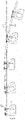
- Fig.1 shows the interrelations among the rail vehicle, truss and column.
- the rail where the rail vehicle (1) runs is installed inside of the cavity of the horizontal support truss (2) and the vertical support column (3) supports the horizontal support truss (2). Due to the rail vehicle adopts light weight design, the horizontal support truss (2) is less loaded so that the span of the horizontal support truss (2) could be over 100m, the section height of truss could be within 1.5m to 2.5m, the height of column could be within 5m to 15m, and the section height of column could be 0.8m to 1.5 m.
- Fig. 2 shows the layout of rail vehicle on urban roads.
- the layout of rail vehicle (1) on a normal urban road could be designed in three basic forms. The first one is that the horizontal support truss (2) and the vertical support column (3) are arranged on the pavement and the rail vehicle runs above the pavement; the second one is the horizontal support truss (2) and the vertical support column (3) are arranged on the central green belt and the rail vehicle (1) runs above the central green belt; and the third one is gantry support frame and the rail vehicle (1) runs above the slow traffic lane.
- Fig. 3 and Fig.4 show the appearance and internal structure of rail vehicle.
- the Fig.3 shows the appearance of rail vehicle.
- the outer structure comprises the rail vehicle compartment(4), the front windshield(7), the door(5), two compartment booms on the front and rear(20) and the computer controlled compartment latch(6), and the connection between the compartment boom(20) and the rail vehicle compartment(4) is provided with the weight limit device.
- the compartment boom(20) is connected to the top of the rail vehicle compartment(4) through a turn plate, when the rail vehicle (1) makes a small radius turn, a rotation will be generated between the compartment boom (20) and the rail vehicle compartment (4).
- the Fig.4 shows internal structure of rail vehicle.
- the internal structure comprises the seat (9), the foldable worktop (10) and the appropriate positions in rail vehicle compartment are provided with the a compartment video monitoring device, air conditions, lightings, network, radio equipment, emergency calling devices and manual control buttons.
- a signal transmitting and receiving device (30) and rail vehicle distance measuring equipment are provided on the front of compartment.
- Fig. 5 -7 show the rail vehicle power system.
- the Fig. 5 is the plan view of the rail vehicle power system (27)
- the Fig.6 is the side level of the rail vehicle power system
- the Fig.7 is the front and rear level of the rail vehicle power system (27).
- the rail vehicle power system (27) comprises two equipment platforms of metal structure, a left side equipment platform (16) and a right side equipment platform (17).
- On the front and rear of the left side equipment platform(16) are respectively provided a front left drive wheel (11) and a rear left driven wheel (13), and on the front left drive wheel (11) is provided a brake component (15).
- On the left side equipment platform (16) is also provided equipment like a battery emergency power supply (21), a distribution box (24), a power receiving contact (23) and an on-board computer.
- equipment like a battery emergency power supply (21), a distribution box (24), a power receiving contact (23) and an on-board computer.
- On the front and the rear of the right side equipment platform (17) are respectively provided a front right drive wheel (12) and a rear right driven wheel (14), and on the front right drive wheel(12) is provided a brake component (15), the right side equipment platform (17) reciprocates up and down relative to the left side equipment platform (16) through the lifting device for right side equipment platform (18) and the rail vehicle power platform connects the compartment(4) through the compartment boom(20).
- Fig. 8 -10 show the interrelation between the track (8) and the rail vehicle power platform (27).
- the track (8) comprises a left side straight rail (29) and a right side turning rail (28).
- the rail on each side comprises an inverted L-shaped rail steel plate (25) and a rail support member (26).
- the rail support member (26) is welded firmly to the rail steel plate at one end and the other end thereof is welded firmly to the horizontal support truss (2).
- the position where the compartment boom is above the bottom of the inverted L-shaped track(8) is provided with an eccentric support wheel(19), the eccentric support wheel(19) is in contact with the side edge of left side and right side rails to resist the eccentric moment generated among the compartment boom (20) and rails on two sides.
- the left side equipment platform (16) is installed above the left side straight rail (29), the right side equipment platform (17) is installed above the right side turning rail (28), and the top face level of left side straight rail (29) is lower than that of the straight section on the right side turning rail (28).
- the right side turning rail (28) When transiting to the turn section from the straight section, the right side turning rail (28) gradually rises in top face level along the running direction of the ail vehicle and the top height difference between the turning and the left side straight rail (29) enables the left side equipment platform (16) of the rail vehicle to deviate from the left side straight rail (29), the right side turning rail (28) curves at the highest point with gradually increasing distance from the left side straight rail (29), and the right side turning rail (28) diverts to the stop station so that the rail vehicle could pull in and stop in the station, or connects to another right side turning rail(28)which is on an intersected or parallel rail line so that the rail vehicle(1) could make a turn, a merging or a shunting.
- the Fig.11 , Fig.12 and Fig.18 show the rail vehicle makes a merging and runs straight.
- the signal transmitting and receiving device (30) bypasses the rail signal device to scan the signal, and the on-board computer receives the signal to start the merging procedure: Firstly the front left drive wheel(11) of the left side equipment platform(16) on the rail vehicle power platform(27) and the lifting device for right side equipment platform(18) are started, the right side equipment platform(17) runs upwards, the front left drive wheel(11) and rear left driven wheel(13) contact the left side straight rail(29) so that the rail vehicle is driven to run straight, then the front right drive wheel(12) and rear right driven wheel(14) stop running, the right side equipment platform(17) is lifted to deviate from the right side turning rail(28), and the rail vehicle(1) driven by the front left drive wheel(11) runs straight along the left side straight rail(2) ahead, thereby completing the
- the cutaway views 1-1, 2-2 and 3-3 show the process that the rail vehicle (1) gradually approaches the left side straight rail (29) from the right side turning rail (28); the cutaway view 4-4 shows the left side equipment platform(16) contacts the left side straight rail(29) to start the front left drive wheel(11) on the left side equipment platform(16); and the cutaway view 5-5 shows the lifting device for right side equipment platform(18) is started so that the right side equipment platform(17) is lifted to deviate from the right side turning rail(28) and the rail vehicle(1) is driven by the left side equipment platform to run straight on the left side straight rail(29).
- the Fig.13 , Fig.14 and Fig.19 show the rail vehicle makes a turn.
- the signal transmitting and receiving device (30) on rail vehicle scans the signal transmitted by the rail signal identification device installed at the turning, and the turn procedure is started as follows when the signal is determined to be the set turning by the on-board computer:
- the lifting device for right side equipment platform (18) is started by the rail vehicle power platform (27) firstly, the right side equipment platform (17) runs upwards, the front right drive wheel(12) and the rear right driven wheel(14) contact the right side turning rail(28) so that the front right drive wheel(12) is started to run along the right side rail ahead, then with the right side turning rail(28) gradually being lifted above the left side straight rail(29), the rail vehicle power platform(27) is lifted so that the left side equipment platform(16) is driven to deviate from the left side rail, and the front left drive wheel(11) stops running.
- the right side turning rail (28) is gradually away from the left side straight rail (29) after the curve, and the rail vehicle(1) makes a turn along the right side turning rail(28) to deviate from the left side straight rail(29), thereby completing the turn procedure.
- the cutaway view 1-1 shows the straight running state of the rail vehicle power platform (27), the left side equipment platform (16) attaches to the left side straight rail (29), the right side equipment platform (17) is lifted by the lifting device for right side equipment platform (18) and there is a certain gap from the right side turning rail (28);
- the cutaway view 2-2 shows the entire right side equipment platform (17) is dropped by the lifting device for right side equipment platform (18), and the right side equipment platform (17) contacts the right side turning rail(28) to start the front right drive wheel(12) on the right side equipment platform(17);
- the cutaway view 3-3 shows that with the rail vehicle power platform running ahead, the top face level of the right side turning rail(28) is gradually lifted above the left side straight rail(29), the entire right side equipment platform
- Fig.15 , Fig.16 and Fig.20 show the rail vehicle makes a shunting.
- On the busy road is provided more than two parallel lines.
- the rail vehicle(1) running on a track B which is parallel to a track A and a C could shunt from the track B onto the track A on the left or onto the track C on the right through a shunting device, the shunting device is a right side turning rail, and the right side turning rail, manufactured into a curve shape, could be connected to the right side turning rail of the track A by bypassing the track B to the left or be connected to the right side turning rail of the track C by bypassing the track C to the right.
- the signal transmitting and receiving device(30) scans the rail signal device, and if the set shunting point is computed and determined by the on-board computer, the turn procedure is started as follows: the turn procedure is firstly started, and the rail vehicle(1) turns along the right side turning rail(28) to deviate from the track B, then bypasses the track B to the left along the shunting device, starts the merging procedure when getting to the right of the track A and merges into the track A; or bypasses the track C to the right along the shunting device, starts the merging procedure when getting the right of the track C and merges into the track C, thereby completing the shunting procedure.
- the cutaway view 1-1 shows the rail vehicle(1) runs straight on the track B before making a shunting, and the left side equipment platform(16) runs straight on the left side straight rail(29); the cutaway view 2-2 and the cutaway view 3-3 show the rail vehicle starts the turn procedure, the right side equipment platform(17) runs on the right side turning rail(28) , and the shunting device guides the rail vehicle to bypass the track C along the curve; and the cutaway view 4-4 shows the merging procedure is started and the rail vehicle makes a merging into the track C.
- the Fig.17 is the schematic diagram showing the rail vehicle pulls into the stop station.
- the turning on the straight rail for pulling into station is provided with a rail signal device.
- the signal transmitting and receiving device (30) of the rail vehicle scans the turn signal of the rail signal device. If the turn signal is determined by the on-board computer or the passenger starts the manual control button, the turn procedure is started.
- the rail vehicle ((1) could run along the right side turning rail (28) directly to the maintenance area; when pulling into the station for dropping off or picking up passengers, the rail vehicle starts a merging procedure at the parallel segment of the left side turning rail (29) and the right side straight rail (28), then the rail vehicle (1) enters into the left side straight rail(29) of the stop station, and stops at the dropping-off area to automatically open the door for passenger to get off, after then, the rail vehicle(1) automatically closes the door and stops at the picking-up area for passenger to get on.
- the rail vehicle (1) doesn't start until the passenger gets on, and the turn procedure thereof is started at the parallel segment of the left side turning rail (29) and the right side straight rail (28) so that the rail vehicle pulls out of the station along the right side turning rail (28) and makes a merging into the main rail.
Claims (9)
- - Zweischieniges hängendes Schienen-Nahverkehrssystem zur Personenbeförderung mit redundanter Stromversorgung und automatischer Steuerung, umfassend ein Fahrbahnsystem, ein Schienenfahrzeug-Energiesystem, ein Schienenfahrzeug-Verkehrsnetzwerksteuersystem, ein Schienenfahrzeug-Kabinensystem, ein Schienenfahrzeug-Stromversorgungssystem und ein Schienenfahrzeug-Haltestationssystem, wobei:
das Fahrbahnsystem ein Fahrbahnträgersystem und eine Fahrbahn (8) umfasst, das Fahrbahnträgersystem eine vertikale Stützsäule (3) und ein horizontales Tragwerk (2) umfasst, ein Schienenfahrzeug (1) die Fahrbahn (8) entlang fährt, die Fahrbahn (8) eine linksseitige gerade Scheine (29) und eine rechtsseitige kurvige Schiene (28) umfasst, die Fahrbahn (8) in einem Innenhohlraum des horizontalen Tragwerks (2) installiert ist, die linksseitige gerade Schiene (29), die auf der linken Seite des Hohlraums installiert ist, eine Hauptstreckenschiene ist, die durchgehend angeordnet ist; die rechtsseitige kurvige Schiene (28), die auf der rechten Seite des Hohlraums installiert ist, einen geraden Abschnitt und einen kurvigen Abschnitt umfasst, der gerade Abschnitt davon so festgelegt ist, dass er unter Einhaltung eines Abstands parallel zur linksseitigen geraden Schiene (29) ist, das Oberseitenniveau des geraden Abschnitts davon höher als das der linksseitigen geraden Schiene (29) ist, das Oberseitenniveau davon während des Übergangs vom geraden Abschnitt zum kurvigen Abschnitt schrittweise ansteigt, der obere Höhenunterschied zwischen der kurvigen und der linksseitigen geraden Schiene (29) es der linksseitigen Einrichtungsplattform (16) des Schienenfahrzeugs (1) ermöglicht, sich von der linksseitigen geraden Schiene (29) zu entfernen, die rechtsseitige kurvige Schiene (28) sich am höchsten Punkt mit einem schrittweise zunehmenden Abstand von der linksseitigen geraden Schiene (29) krümmt, und die rechtsseitige kurvige Schiene (28) zur Haltstation abzweigt, so dass das Schienenfahrzeug in die Haltestation einfahren und in der Station anhalten könnte, oder sich mit einer anderen rechtsseitigen kurvigen Schiene (28) verbindet, die auf einem kreuzenden oder parallelen Schienenstrang ist, so dass das Schienenfahrzeug (1) ein Abbiegen, ein Einfädeln oder ein Rangieren durchführen könnte; das Schienenfahrzeug-Energiesystem einen Kabinenarm (20), eine Schienenfahrzeug-Energieplattform (27) und ein exzentrisches Stützrad (19) umfasst, die Schienenfahrzeug-Energieplattform (27) eine linksseitige Einrichtungsplattform (16) und eine rechtsseitige Einrichtungsplattform (17) umfasst, die linksseitige Einrichtungsplattform (16) mit einem vorderen linken Antriebsrad (11) und einem hinteren linken Antriebsrad (13) versehen ist, die rechtsseitige Einrichtungsplattform (17) mit einem vorderen rechten Antriebsrad (12), einem hinteren rechten Antriebsrad (14) und einer Hebevorrichtung für die rechtsseitige Einrichtungsplattform (18) versehen ist, das untere Ende des Kabinenarms (20) mit einem exzentrischen Stützrad (19) versehen ist, und die Rollfläche des exzentrischen Stützrads (19) mit der Unterseite der Fahrbahn (8) in Kontakt ist; der Kabinenarm (20) durch eine Drehplatte mit dem oberen Ende der Schienenfahrzeugkabine (4) flexibel verbunden ist, wenn das Schienenfahrzeug (1) einen kleinen Wendekreis macht, eine Drehung zwischen dem Kabinenarm (20) und der Schienenfahrzeugkabine (4) herbeigeführt wird, die linksseitige Einrichtungsplattform (16) über der linksseitigen gerade Schiene (29) installiert ist, die rechtsseitige Einrichtungsplattform (17) über der rechtsseitigen kurvigen Schiene (28) installiert ist, und die rechtsseitige Einrichtungsplattform (17) sich in Bezug auf die linksseitige Einrichtungsplattform (16) durch die Hebevorrichtung für die rechtsseitige Einrichtungsplattform (18) auf- und abbewegt; wenn das Schienenfahrzeug (1) gerade fährt, das vordere linke Antriebsrad (11) und das hintere linke Antriebsrad (13) das Schienenfahrzeug (1) aufgrund dessen, dass die linksseitige Einrichtungsplattform (16) über der linksseitigen geraden Schiene (29) ist, so antreiben, dass es entlang der linksseitigen geraden Schiene (29) geradeaus fährt, wenn das Schienenfahrzeug (1) in die Station einfahren, einfädeln, abzweigen oder aufgrund von Störungen sich dringend von der linksseitigen geraden Schiene (29) entfernen muss, sich die gesamte rechtsseitige Einrichtungsplattform (17) unter Einwirkung der Hebevorrichtung für die rechtsseitige Einrichtungsplattform (18) nach unten bewegt, um mit der rechtsseitigen kurvigen Schiene (28) in Kontakt zu treten, und gleichzeitig das vordere rechte Antriebsrad (12) gestartet wird, um das Schienenfahrzeug (1) anzutreiben, wenn das Schienenfahrzeug (1) entlang des geraden Abschnitts der rechtsseitigen kurvigen Schiene (28) zum kurvigen Abschnitt gelangt, das Oberseitenniveau davon über das der linksseitigen geraden Schiene (29) schrittweise ansteigt und die gesamte Schienenfahrzeug-Energieplattform (27) mit dem ansteigenden Niveau der rechtsseitigen kurvigen Schiene (28) so angehoben wird, dass die linksseitige Einrichtungsplattform (16) sich von der linksseitigen geraden Schiene (29) entfernt, woraufhin das Schienenfahrzeug (1) in den kurvigen Abschnitt auf der rechtsseitigen kurvigen Schiene (28) eintritt und entlang der Kurve abbiegt, um sich von der linksseitigen geraden Schiene (29) zu entfernen, um dadurch das Abbiegen des Schienenfahrzeugs (1) durchzuführen, wenn dagegen der kurvige Abschnitt in den geraden Abschnitt übergeht, das Niveau der rechtsseitigen kurvigen Schiene (28) schrittweise absinkt, und der Abstand zwischen der rechtsseitigen kurvigen Schiene (28) und der linksseitigen geraden Schiene (29) schrittweise kleiner wird, wenn der gerade Abschnitt auf der rechtsseitigen kurvigen Schiene (28) erreicht wird, die linksseitige Einrichtungsplattform (16) mit der linksseitigen geraden Schiene (29) in Kontakt tritt, das vordere linke Antriebsrad (11) auf der linksseitigen Einrichtungsplattform (16) gestartet wird, und das vordere rechte Antriebsrad (12) auf der rechtsseitigen Einrichtungsplattform (17) unter Einwirkung der Hebevorrichtung für die rechtsseitige Einrichtungsplattform (18) geschlossen wird, die rechtsseitige Einrichtungsplattform (17) angehoben und von der rechtsseitigen kurvigen Schiene (28) entfernt wird, und das Fahrzeug in den Zustand des Geradefahrens eintritt; das Schienenfahrzeug-Verkehrsnetzwerksteuersystem ein zentrales Steuercomputersystem, ein Bordcomputersteuersystem, eine Schienensignalidentifizierungsvorrichtung, und ein Haltestations-Computersteuersystem umfasst, das zentrale Steuercomputersystem einen großen zentralen Steuercomputer und ein Hilfssystem davon umfasst, der zentrale Steuercomputer Reservierungs- und Zielinformationen jedes Schienenfahrzeugs (1), Haltestationsinformationen und Störungsinformationen der Fahrbahn (8) und des Schienenfahrzeugs (1) zur Datenverarbeitung sammelt und automatische Steuerung über Gesamtplanung, Betriebsleitungsdesign und Notbeseitigung von Störungen für das Schienenfahrzeug (1) implementiert, das Bordcomputersteuersystem einen Bordcomputer, eine Schienenfahrzeugsignalsende- und -empfangsvorrichtung (30), einen computergesteuerten Kabinenverschluss (6) und Datenleitungen umfasst, der Bordcomputer die Steuerprozeduren für das Schienenfahrzeug (1) in verschiedenen Zuständen speichert, wenn die vom Benutzer festgelegten Zielinformationen über den computergesteuerten Kabinenverschluss (6) erhalten werden, der Bordcomputer die Zielinformationen auf den zentralen Steuercomputer hochlädt, der zentrale Steuercomputer die optimale Betriebsleitung des Schienenfahrzeugs (1) berechnet und die optimale Betriebsleitung des Schienenfahrzeugs an den Bordcomputer zurücksendet,der Bordcomputer die durch die Signalsende- und -empfangsvorrichtung (30) gesammelten Signaldaten berechnet und verarbeitet, um den Betriebsbefehl des Schienenfahrzeugs (1) zu erhalten, und der Bordcomputer das Schienenfahrzeug (1) zum Beschleunigen, Entschleunigen und Bremsen durch Einstellen des Eingangsstroms und der Eingangsspannung der Schienenfahrzeug-Energieplattform (27) und Öffnen und Schließen von Bremskomponenten (15) steuert und das Schienenfahrzeug (1) durch Starten der Hebevorrichtung für die rechtsseitige Einrichtungsplattform (18) zum Durchführen eines Abbiegens, eines Einfädelns oder eines Rangierens befähigt. - - Schienenverkehrssystem nach Anspruch 1, dadurch gekennzeichnet, dass das Schienenfahrzeug-Kabinensystem ein Schienenfahrzeugkabine (4), einen Sitz (9), eine zusammenklappbare Arbeitsplatte (10) und eine Tür (5) umfasst, die Schienenfahrzeugkabine (4) durch zwei Kabinenarme (20) auf der Vorderseite und der Hinterseite mit der Schienenfahrzeug-Energieplattform (27) verbunden ist, und innerhalb der Schienenfahrzeugkabine (4) ein computergesteuerter Kabinenverschluss (6), eine Kabinen-Videoüberwachungsvorrichtung, eine Klimaanlage, Beleuchtungen, eine Schienenfahrzeug-Gewichtsbegrenzungsvorrichtung, ein Netzwerk, eine Funkeinrichtung, ein Notrufvorrichtung und eine manuelle Steuertaste vorgesehen sind.
- - Schienenverkehrssystem nach Anspruch 1, dadurch gekennzeichnet, dass das Schienenfahrzeug-Stromversorgungssystem Transformator-Unterstationen, die entlang des Weges angeordnet sind, Hochspannungsleitungen, ein schienenfahrzeuginternes Stromversorgungssystem und ein Fahrdrahtnetzwerk der schieneninternen Stromversorgung (22) umfasst, das schienenfahrzeuginterne Stromversorgungssystem einen Stromaufnahmekontakt (23), eine Schienenfahrzeug-Verteilerkasten (24), eine Batterienotstromversorgung (21), eine Energieplattform-Stromversorgungsleitung, eine Kabinen-Stromversorgungsleitung und ein Schwachstromsystem umfasst, Übertragungs-Unterstationen entlang der Fahrbahn (8) angeordnet sind, jede Übertragungs-Unterstation durch ununterbrochenen Strom von nicht weniger als zwei Stadtstromkreisen versorgt wird, die Übertragungsleitung entlang der Innenseite des horizontalen Tragwerks (2) angeordnet ist, um das Stromversorgungs-Fahrdrahtnetzwerk (22) mit Strom zu versorgen, das interne Stromversorgungssystem des Schienenfahrzeugs (1) die Stromversorgung durch den Stromaufnahmekontakt (23) verbindet und die Batterienotstromversorgung (21), die Schienenfahrzeug-Energieplattform (27), die Schienenfahrzeugkabine (4) und das Schwachstromsystem durch den Verteilerkasten (24) mit Strom versorgt, und die Batterienotstromversorgung (21) auf der linksseitigen Einrichtungsplattform (16) der Schienenfahrzeug-Energieplattform (27) installiert ist.
- - Schienenverkehrssystem nach Anspruch 1, dadurch gekennzeichnet, dass beide Außenseiten des vorderen linken Antriebsrads (11) und des vorderen rechten Antriebsrads (12) mit einer Bremskomponente (15) versehen sind, und die Hebevorrichtung für die rechtsseitige Einrichtungsplattform (18) einen mechanischen, elektromagnetischen oder hydraulischen Modus als Antriebsenergie annimmt.
- - Schienenverkehrssystem nach Anspruch 1, dadurch gekennzeichnet, dass die Fahrbahn (8) eine Strukturform eines umgekehrten Ls annimmt, und die Fahrbahn (8) eine Schienenstahlplatte (25) in Form eines umgekehrten Ls und ein Schienenstützelement (26) umfasst.
- - Schienenverkehrssystem nach Anspruch 1, dadurch gekennzeichnet, dass die Schienenfahrzeug-Energieplattform (27) mit der Schienenfahrzeugkabine (4) durch zwei Kabinenarme (20) auf der Vorderseite und der Hinterseite verbunden ist, beide der Kabinenarme (20) auf der Vorderseite und der Hinterseite mit einem exzentrischen Stützrad (19) versehen sind, und die Rollflächen von exzentrischen Stützrädern auf dem vorderen und dem hinteren Kabinenarm (20) jeweils mit der linken und der rechten Seite der Unterseite der Fahrbahn (8) in Kontakt sind, um dem exzentrischen Moment zu widerstehen, das zwischen den Kabinenarmen (20) und den beiden Seiten der Fahrbahn (8) erzeugt wird.
- - Schienenverkehrssystem nach Anspruch 1, dadurch gekennzeichnet, dass die Fahrbahn (8) mit einer Signalvorrichtung am Einfädelungspunkt versehen ist, der entsprechende Punkt der geraden Schiene mit einer Signalempfangs- und -sendevorrichtung für das Einfädelungssignal vorgesehen ist, wenn das Fahrzeug die Einfädelungssignalvorrichtung passiert, das Fahrzeugpassiersignal an die Signalempfangs- und-sendevorrichtung für das Einfädelungssignal gesendet wird, und wenn das auf der geraden Schiene fahrende Fahrzeug vorbeikommt und das Signal erhält, dass ein Schienenfahrzeug sich in die Schiene einfädelt, das Signal durch den Bordcomputer davon berechnet wird, um zu bestimmen, ob es beschleunigen oder entschleunigen soll, um dem Schienenfahrzeug, das sich in die Schiene einfädelt, Vorfahrt zu gewähren.
- - Schienenverkehrssystem nach Anspruch 1, dadurch gekennzeichnet, dass das Schienenfahrzeug (1), das auf einer Fahrbahn B fährt, die parallel zu einer Fahrbahn A und einer Fahrbahn C ist, durch eine Rangiervorrichtung von der Fahrbahn B auf die Fahrbahn A auf der linken Seite oder auf die Fahrbahn C auf der rechten Seite rangieren könnte, die Rangiervorrichtung eine rechtsseitige kurvige Schiene ist, und die rechtsseitige kurvige Schiene, die in einer Kurvenform ausgeführt ist, durch Umleiten der Fahrbahn B nach links mit der rechtsseitigen kurvigen Schiene der Fahrbahn A verbunden werden könnte oder durch Umleiten der Fahrbahn C nach rechts mit der rechtsseitigen kurvigen Schiene der Fahrbahn C verbunden werden könnte.
- - Schienenverkehrssystem nach Anspruch 1, dadurch gekennzeichnet, dass das Haltestationssystem einen Abstellbereich, eine Haltestationsfahrbahn, eine Ausstiegsplattform, eine Aufnahmeplattform, eine Schienenfahrzeug-Wartungsplattform und eine Haltestationssteuerzentrale umfasst, der Abstellbereich die Baulücke, die auf beiden Seiten der Schienenstrangs angeordnet ist, ein Untergeschoss und einen Innenraum eines großflächigen Gebäudes umfasst, die Haltestationsfahrbahn eine rechtsseitige kurvige Schiene (28) und mindestens eine linksseitige gerade Schiene (29) umfasst, die rechtsseitige kurvige Schiene (28), die sich von der Wende der Fahrbahn (8) innerhalb des Fahrbahnsystems erstreckt, in der Höhe schrittweise bis unter die Unterseite des Schienenfahrzeugs (1) und unmittelbar über den Boden der Haltestation abnimmt, die rechtsseitige kurvige Schiene (28) in der Haltestation sich entlang der Außenseite des Abstellbereichs krümmt, um einen nach außen vorstehenden Bogen zu bilden, und nach ihrer Entfernung von der Station schrittweise in der Höhe ansteigt, um sich in die Fahrbahn (8) innerhalb des Fahrbahnsystems einzufädeln, eine linksseitige gerade Schiene (29) der Haltestation innerhalb des Bogens angeordnet ist, ein paralleles Segment (31), das mit der rechtsseitigen kurvigen Schiene (28) an beiden Enden der linksseitigen geraden Schiene (29) verbunden ist, vorgesehen ist, damit das Schienenfahrzeug (1) sich von der rechtsseitigen kurvigen Schiene (28) in die linksseitige gerade Schiene (29) einfädelt, wenn es in die Station einfährt, und von der linksseitigen geraden Schiene (29) auf die rechtsseitige kurvige Schiene (28) rangiert, wenn es aus der Station ausfährt, die linksseitige gerade Schiene (29) der Haltestation verwendet wird, damit das Schienenfahrzeug (1) Passagiere aufnimmt und aussteigen lässt, der Eingang davon als die Ausstiegsplattform festgelegt ist, der Ausgang davon als die Aufnahmeplattform festgelegt ist, und die Bogenspitze der rechtsseitigen kurvigen Schiene (28) der Haltestation als die Wartungsplattform des Schienenfahrzeugs (1) festgelegt ist.
Applications Claiming Priority (2)
| Application Number | Priority Date | Filing Date | Title |
|---|---|---|---|
| CN201710098937.0A CN106864464B (zh) | 2017-02-23 | 2017-02-23 | 个人悬挂式双轨道双动力自动控制轻型轨道交通系统 |
| PCT/CN2018/076936 WO2018153339A1 (zh) | 2017-02-23 | 2018-02-22 | 个人悬挂式双轨道双动力自动控制轻型轨道交通系统 |
Publications (3)
| Publication Number | Publication Date |
|---|---|
| EP3594079A1 EP3594079A1 (de) | 2020-01-15 |
| EP3594079A4 EP3594079A4 (de) | 2021-01-20 |
| EP3594079B1 true EP3594079B1 (de) | 2022-06-29 |
Family
ID=59168473
Family Applications (1)
| Application Number | Title | Priority Date | Filing Date |
|---|---|---|---|
| EP18756952.0A Active EP3594079B1 (de) | 2017-02-23 | 2018-02-22 | Hängendes doppelschienen- und doppelenergie-lichtschienenverkehrssystem mit automatischer steuerung zur personenbeförderung |
Country Status (4)
| Country | Link |
|---|---|
| EP (1) | EP3594079B1 (de) |
| CN (1) | CN106864464B (de) |
| SG (1) | SG11201907635VA (de) |
| WO (1) | WO2018153339A1 (de) |
Families Citing this family (27)
| Publication number | Priority date | Publication date | Assignee | Title |
|---|---|---|---|---|
| CN106864464B (zh) * | 2017-02-23 | 2018-07-06 | 万普华 | 个人悬挂式双轨道双动力自动控制轻型轨道交通系统 |
| CN107351847B (zh) * | 2017-07-27 | 2023-06-09 | 佛山市梦真营机电有限公司 | 一种空中轨道共享电车 |
| CN109532879B (zh) * | 2017-09-22 | 2021-01-05 | 中车唐山机车车辆有限公司 | 一种微轨车辆系统及具有防晃功能的站台 |
| CN109532876B (zh) * | 2017-09-22 | 2021-02-26 | 中车唐山机车车辆有限公司 | 一种微轨车厢 |
| CN109532868B (zh) * | 2017-09-22 | 2021-05-04 | 中车唐山机车车辆有限公司 | 一种微轨交通系统 |
| CN109532870B (zh) * | 2017-09-22 | 2021-02-26 | 中车唐山机车车辆有限公司 | 一种微轨车辆系统 |
| CN109532878B (zh) * | 2017-09-22 | 2021-03-19 | 中车唐山机车车辆有限公司 | 一种微轨走行机构 |
| AU2018368752A1 (en) * | 2017-11-17 | 2020-07-02 | Sheeghra LLC | System and method for switching railcars using a static rail-track configuration |
| CN108162984B (zh) * | 2017-12-08 | 2023-09-05 | 杭州久智自动化技术有限公司 | 轨道网的基本运行子段 |
| CN108238064B (zh) * | 2018-02-06 | 2024-01-23 | 中铁二院工程集团有限责任公司 | 悬挂式单轨道岔可动轨转辙机构 |
| CN108382404A (zh) * | 2018-03-21 | 2018-08-10 | 段绪松 | 一种新型城市轨道交通系统 |
| CN109178019A (zh) * | 2018-08-10 | 2019-01-11 | 杭州飞遁科技有限公司 | 轨道交通系统的合轨装置 |
| CN109178021A (zh) * | 2018-08-10 | 2019-01-11 | 杭州飞遁科技有限公司 | 轨道交通系统的分轨装置 |
| CN109178020A (zh) * | 2018-08-10 | 2019-01-11 | 杭州飞遁科技有限公司 | 一种轨道交通系统的分轨装置 |
| CN109229111A (zh) * | 2018-09-09 | 2019-01-18 | 深圳大行同宇科技有限公司 | 一种小型农用架空轨道车 |
| SG11202104310QA (en) * | 2018-10-29 | 2021-05-28 | Murata Machinery Ltd | Traveling vehicle system |
| CN110203255B (zh) * | 2019-05-29 | 2021-06-11 | 江苏飞梭智行设备有限公司 | 一种轨道交通无人驾驶车辆安全并轨的方法 |
| CN110126887B (zh) * | 2019-05-29 | 2021-06-04 | 江苏飞梭智行设备有限公司 | 一种提高车辆转弯并轨效率的方法 |
| CN110576752B (zh) * | 2019-09-23 | 2023-08-22 | 万泽霈 | 个人自动控制轻型可变轨磁悬浮轨道交通系统 |
| CN110723168B (zh) * | 2019-09-30 | 2023-08-18 | 江苏飞梭智行设备有限公司 | 一种平移变轨机构 |
| CN112744255B (zh) * | 2019-10-31 | 2023-06-02 | 江苏飞梭智行设备有限公司 | 一种防脱轨的变轨装置及轨道交通系统 |
| CN111469885B (zh) * | 2020-04-03 | 2023-02-17 | 雷冰 | 轨道交通系统中的移动单元及轨道交通系统 |
| CN111824186A (zh) * | 2020-06-24 | 2020-10-27 | 宁伟 | 全时智能直达单人悬轨交通 |
| CN112593804B (zh) * | 2020-12-11 | 2022-07-26 | 中车唐山机车车辆有限公司 | 一种车辆的车门控制方法,装置及系统 |
| CN112614376B (zh) * | 2020-12-11 | 2022-11-22 | 中车唐山机车车辆有限公司 | 一种车辆的行车控制方法、装置及系统 |
| CN114108399B (zh) * | 2021-10-11 | 2023-06-16 | 北京天玛智控科技股份有限公司 | 一种巡检机器人的底盘与相配合的单轨双梁式轨道 |
| CN114537451B (zh) * | 2022-02-18 | 2023-06-06 | 中建空列(北京)科技有限公司 | 悬挂式空铁氢能源供电系统 |
Family Cites Families (19)
| Publication number | Priority date | Publication date | Assignee | Title |
|---|---|---|---|---|
| US3830163A (en) * | 1972-11-29 | 1974-08-20 | Monocab Inc | Monorail vehicle switching arrangement |
| US4016818A (en) | 1975-09-02 | 1977-04-12 | Ellzey Floyd P | Monorail switch |
| FR2694532B1 (fr) * | 1992-08-06 | 1994-10-07 | Christian Thevenet | Système de transport à correction statique d'assiette. |
| KR100936582B1 (ko) * | 2001-03-01 | 2010-01-13 | 케스케이드 엔지니어링 인코퍼레이티드 | 개별 운송 시스템 |
| DE10159678B4 (de) | 2001-12-05 | 2017-09-21 | Dürr Systems Ag | Schienengebundenes Transportsystem |
| CN1429726A (zh) * | 2003-01-30 | 2003-07-16 | 沈湧 | 小型车辆的轨道交通系统 |
| US7499186B2 (en) * | 2003-11-25 | 2009-03-03 | Mhe Technologies, Inc. | Laser survey device |
| CN100351124C (zh) * | 2004-11-15 | 2007-11-28 | 李岭群 | 吊轨永磁吸引悬浮与导向路-车系统 |
| CN101134464A (zh) * | 2007-09-17 | 2008-03-05 | 戴苏才 | A/b/c组合路线网与轨道交通 |
| CN102211584A (zh) * | 2010-04-08 | 2011-10-12 | 刘耀东 | 斜拉桥式空铁环城电气化电力公交车 |
| TWM404158U (en) * | 2010-06-16 | 2011-05-21 | Mobasher JP | Smart transit rail system |
| CN202987140U (zh) * | 2012-11-26 | 2013-06-12 | 河南重工起重机集团有限公司 | 用于旅客运输的改进型空中轨道交通系统 |
| KR101521498B1 (ko) * | 2013-05-31 | 2015-05-19 | 주식회사 에스에프에이 | 반송대차 및 이를 이용하는 반송시스템 |
| CN104015731A (zh) * | 2014-05-30 | 2014-09-03 | 赵毅 | 大运能直达轨交系统 |
| JP2016002904A (ja) * | 2014-06-18 | 2016-01-12 | 株式会社明電舎 | 天井走行台車 |
| CN104787056A (zh) * | 2015-04-30 | 2015-07-22 | 罗运明 | 一种轨道交通的实现方法以及用于该方法中的车辆 |
| CN105774820B (zh) * | 2016-05-18 | 2018-01-23 | 中唐空铁科技有限公司 | 空铁公交系统 |
| CN106114529A (zh) * | 2016-08-15 | 2016-11-16 | 济南承乾工程技术有限公司 | 一站式超轻型电动城市轨道交通系统 |
| CN106864464B (zh) * | 2017-02-23 | 2018-07-06 | 万普华 | 个人悬挂式双轨道双动力自动控制轻型轨道交通系统 |
-
2017
- 2017-02-23 CN CN201710098937.0A patent/CN106864464B/zh active Active
-
2018
- 2018-02-22 SG SG11201907635VA patent/SG11201907635VA/en unknown
- 2018-02-22 EP EP18756952.0A patent/EP3594079B1/de active Active
- 2018-02-22 WO PCT/CN2018/076936 patent/WO2018153339A1/zh unknown
Also Published As
| Publication number | Publication date |
|---|---|
| WO2018153339A1 (zh) | 2018-08-30 |
| EP3594079A1 (de) | 2020-01-15 |
| SG11201907635VA (en) | 2019-09-27 |
| CN106864464B (zh) | 2018-07-06 |
| CN106864464A (zh) | 2017-06-20 |
| EP3594079A4 (de) | 2021-01-20 |
Similar Documents
| Publication | Publication Date | Title |
|---|---|---|
| EP3594079B1 (de) | Hängendes doppelschienen- und doppelenergie-lichtschienenverkehrssystem mit automatischer steuerung zur personenbeförderung | |
| RU2682122C2 (ru) | Специализированное надземное средство общественного транспорта | |
| CN109532868B (zh) | 一种微轨交通系统 | |
| CN107600077B (zh) | 悬挂式智能立体轨道交通系统及方法 | |
| US8375865B2 (en) | Overhead suspended personal transportation and freight delivery surface transportation system | |
| US5598783A (en) | Integrated transportation system including transfer vehicles | |
| WO2004068438A1 (fr) | Systeme de circulation de mini-vehicules sur des rails | |
| CN201951460U (zh) | 悬挂式轨道公交系统 | |
| CN102114861A (zh) | 区域无线网络传递信息的智能化轨道交通系统 | |
| KR20180111887A (ko) | 자동 운송 시스템 | |
| JP2013500187A (ja) | 大量輸送システム | |
| CN101905702A (zh) | 无线网络控制的轨道交通系统 | |
| GB2305645A (en) | Overhead monorail - lowers carriage to load/unload passengers or goods | |
| CN109532875B (zh) | 一种微轨轨道系统 | |
| US10358147B2 (en) | Personalized elevated urban transport | |
| CN110576752A (zh) | 个人自动控制轻型可变轨磁悬浮轨道交通系统 | |
| CN102002900A (zh) | 一种快速公交系统 | |
| CN103264702A (zh) | 一种空中轨道交通运输系统网络的构成方法 | |
| CN108382404A (zh) | 一种新型城市轨道交通系统 | |
| WO2018228161A1 (zh) | 轨道车辆控制系统、轨道车辆、轨道系统以及运输系统 | |
| CN201932156U (zh) | 高架与地下传送带公交系统 | |
| CN109532860B (zh) | 一种微轨轨道系统 | |
| CN208789668U (zh) | 采用太阳能、风能和重力势能驱动的城市缆车运载系统 | |
| CN106886971A (zh) | 无碳高效智能随意行交通系统 | |
| CN108374587B (zh) | 一种横跨道路或河流的空中立体车库 |
Legal Events
| Date | Code | Title | Description |
|---|---|---|---|
| STAA | Information on the status of an ep patent application or granted ep patent |
Free format text: STATUS: THE INTERNATIONAL PUBLICATION HAS BEEN MADE |
|
| PUAI | Public reference made under article 153(3) epc to a published international application that has entered the european phase |
Free format text: ORIGINAL CODE: 0009012 |
|
| STAA | Information on the status of an ep patent application or granted ep patent |
Free format text: STATUS: REQUEST FOR EXAMINATION WAS MADE |
|
| 17P | Request for examination filed |
Effective date: 20191204 |
|
| AK | Designated contracting states |
Kind code of ref document: A1 Designated state(s): AL AT BE BG CH CY CZ DE DK EE ES FI FR GB GR HR HU IE IS IT LI LT LU LV MC MK MT NL NO PL PT RO RS SE SI SK SM TR |
|
| AX | Request for extension of the european patent |
Extension state: BA ME |
|
| DAV | Request for validation of the european patent (deleted) | ||
| DAX | Request for extension of the european patent (deleted) | ||
| A4 | Supplementary search report drawn up and despatched |
Effective date: 20201221 |
|
| RIC1 | Information provided on ipc code assigned before grant |
Ipc: E01B 25/26 20060101ALI20201215BHEP Ipc: B61B 3/02 20060101AFI20201215BHEP |
|
| REG | Reference to a national code |
Ref country code: DE Ref legal event code: R079 Ref document number: 602018037350 Country of ref document: DE Free format text: PREVIOUS MAIN CLASS: B61B0003000000 Ipc: B61B0003020000 |
|
| GRAP | Despatch of communication of intention to grant a patent |
Free format text: ORIGINAL CODE: EPIDOSNIGR1 |
|
| STAA | Information on the status of an ep patent application or granted ep patent |
Free format text: STATUS: GRANT OF PATENT IS INTENDED |
|
| RIC1 | Information provided on ipc code assigned before grant |
Ipc: E01B 25/26 20060101ALI20211213BHEP Ipc: B61B 3/02 20060101AFI20211213BHEP |
|
| INTG | Intention to grant announced |
Effective date: 20220119 |
|
| GRAS | Grant fee paid |
Free format text: ORIGINAL CODE: EPIDOSNIGR3 |
|
| GRAA | (expected) grant |
Free format text: ORIGINAL CODE: 0009210 |
|
| STAA | Information on the status of an ep patent application or granted ep patent |
Free format text: STATUS: THE PATENT HAS BEEN GRANTED |
|
| AK | Designated contracting states |
Kind code of ref document: B1 Designated state(s): AL AT BE BG CH CY CZ DE DK EE ES FI FR GB GR HR HU IE IS IT LI LT LU LV MC MK MT NL NO PL PT RO RS SE SI SK SM TR |
|
| REG | Reference to a national code |
Ref country code: CH Ref legal event code: EP |
|
| REG | Reference to a national code |
Ref country code: DE Ref legal event code: R096 Ref document number: 602018037350 Country of ref document: DE |
|
| REG | Reference to a national code |
Ref country code: AT Ref legal event code: REF Ref document number: 1501162 Country of ref document: AT Kind code of ref document: T Effective date: 20220715 |
|
| REG | Reference to a national code |
Ref country code: IE Ref legal event code: FG4D |
|
| REG | Reference to a national code |
Ref country code: LT Ref legal event code: MG9D |
|
| PG25 | Lapsed in a contracting state [announced via postgrant information from national office to epo] |
Ref country code: SE Free format text: LAPSE BECAUSE OF FAILURE TO SUBMIT A TRANSLATION OF THE DESCRIPTION OR TO PAY THE FEE WITHIN THE PRESCRIBED TIME-LIMIT Effective date: 20220629 Ref country code: NO Free format text: LAPSE BECAUSE OF FAILURE TO SUBMIT A TRANSLATION OF THE DESCRIPTION OR TO PAY THE FEE WITHIN THE PRESCRIBED TIME-LIMIT Effective date: 20220929 Ref country code: LT Free format text: LAPSE BECAUSE OF FAILURE TO SUBMIT A TRANSLATION OF THE DESCRIPTION OR TO PAY THE FEE WITHIN THE PRESCRIBED TIME-LIMIT Effective date: 20220629 Ref country code: HR Free format text: LAPSE BECAUSE OF FAILURE TO SUBMIT A TRANSLATION OF THE DESCRIPTION OR TO PAY THE FEE WITHIN THE PRESCRIBED TIME-LIMIT Effective date: 20220629 Ref country code: GR Free format text: LAPSE BECAUSE OF FAILURE TO SUBMIT A TRANSLATION OF THE DESCRIPTION OR TO PAY THE FEE WITHIN THE PRESCRIBED TIME-LIMIT Effective date: 20220930 Ref country code: FI Free format text: LAPSE BECAUSE OF FAILURE TO SUBMIT A TRANSLATION OF THE DESCRIPTION OR TO PAY THE FEE WITHIN THE PRESCRIBED TIME-LIMIT Effective date: 20220629 Ref country code: BG Free format text: LAPSE BECAUSE OF FAILURE TO SUBMIT A TRANSLATION OF THE DESCRIPTION OR TO PAY THE FEE WITHIN THE PRESCRIBED TIME-LIMIT Effective date: 20220929 |
|
| REG | Reference to a national code |
Ref country code: NL Ref legal event code: MP Effective date: 20220629 |
|
| REG | Reference to a national code |
Ref country code: AT Ref legal event code: MK05 Ref document number: 1501162 Country of ref document: AT Kind code of ref document: T Effective date: 20220629 |
|
| PG25 | Lapsed in a contracting state [announced via postgrant information from national office to epo] |
Ref country code: RS Free format text: LAPSE BECAUSE OF FAILURE TO SUBMIT A TRANSLATION OF THE DESCRIPTION OR TO PAY THE FEE WITHIN THE PRESCRIBED TIME-LIMIT Effective date: 20220629 Ref country code: LV Free format text: LAPSE BECAUSE OF FAILURE TO SUBMIT A TRANSLATION OF THE DESCRIPTION OR TO PAY THE FEE WITHIN THE PRESCRIBED TIME-LIMIT Effective date: 20220629 |
|
| PG25 | Lapsed in a contracting state [announced via postgrant information from national office to epo] |
Ref country code: NL Free format text: LAPSE BECAUSE OF FAILURE TO SUBMIT A TRANSLATION OF THE DESCRIPTION OR TO PAY THE FEE WITHIN THE PRESCRIBED TIME-LIMIT Effective date: 20220629 |
|
| PG25 | Lapsed in a contracting state [announced via postgrant information from national office to epo] |
Ref country code: SM Free format text: LAPSE BECAUSE OF FAILURE TO SUBMIT A TRANSLATION OF THE DESCRIPTION OR TO PAY THE FEE WITHIN THE PRESCRIBED TIME-LIMIT Effective date: 20220629 Ref country code: SK Free format text: LAPSE BECAUSE OF FAILURE TO SUBMIT A TRANSLATION OF THE DESCRIPTION OR TO PAY THE FEE WITHIN THE PRESCRIBED TIME-LIMIT Effective date: 20220629 Ref country code: RO Free format text: LAPSE BECAUSE OF FAILURE TO SUBMIT A TRANSLATION OF THE DESCRIPTION OR TO PAY THE FEE WITHIN THE PRESCRIBED TIME-LIMIT Effective date: 20220629 Ref country code: PT Free format text: LAPSE BECAUSE OF FAILURE TO SUBMIT A TRANSLATION OF THE DESCRIPTION OR TO PAY THE FEE WITHIN THE PRESCRIBED TIME-LIMIT Effective date: 20221031 Ref country code: ES Free format text: LAPSE BECAUSE OF FAILURE TO SUBMIT A TRANSLATION OF THE DESCRIPTION OR TO PAY THE FEE WITHIN THE PRESCRIBED TIME-LIMIT Effective date: 20220629 Ref country code: EE Free format text: LAPSE BECAUSE OF FAILURE TO SUBMIT A TRANSLATION OF THE DESCRIPTION OR TO PAY THE FEE WITHIN THE PRESCRIBED TIME-LIMIT Effective date: 20220629 Ref country code: AT Free format text: LAPSE BECAUSE OF FAILURE TO SUBMIT A TRANSLATION OF THE DESCRIPTION OR TO PAY THE FEE WITHIN THE PRESCRIBED TIME-LIMIT Effective date: 20220629 |
|
| PG25 | Lapsed in a contracting state [announced via postgrant information from national office to epo] |
Ref country code: PL Free format text: LAPSE BECAUSE OF FAILURE TO SUBMIT A TRANSLATION OF THE DESCRIPTION OR TO PAY THE FEE WITHIN THE PRESCRIBED TIME-LIMIT Effective date: 20220629 Ref country code: IS Free format text: LAPSE BECAUSE OF FAILURE TO SUBMIT A TRANSLATION OF THE DESCRIPTION OR TO PAY THE FEE WITHIN THE PRESCRIBED TIME-LIMIT Effective date: 20221029 |
|
| REG | Reference to a national code |
Ref country code: DE Ref legal event code: R097 Ref document number: 602018037350 Country of ref document: DE |
|
| PG25 | Lapsed in a contracting state [announced via postgrant information from national office to epo] |
Ref country code: AL Free format text: LAPSE BECAUSE OF FAILURE TO SUBMIT A TRANSLATION OF THE DESCRIPTION OR TO PAY THE FEE WITHIN THE PRESCRIBED TIME-LIMIT Effective date: 20220629 |
|
| PG25 | Lapsed in a contracting state [announced via postgrant information from national office to epo] |
Ref country code: DK Free format text: LAPSE BECAUSE OF FAILURE TO SUBMIT A TRANSLATION OF THE DESCRIPTION OR TO PAY THE FEE WITHIN THE PRESCRIBED TIME-LIMIT Effective date: 20220629 Ref country code: CZ Free format text: LAPSE BECAUSE OF FAILURE TO SUBMIT A TRANSLATION OF THE DESCRIPTION OR TO PAY THE FEE WITHIN THE PRESCRIBED TIME-LIMIT Effective date: 20220629 |
|
| PGFP | Annual fee paid to national office [announced via postgrant information from national office to epo] |
Ref country code: FR Payment date: 20230221 Year of fee payment: 6 |
|
| PLBE | No opposition filed within time limit |
Free format text: ORIGINAL CODE: 0009261 |
|
| STAA | Information on the status of an ep patent application or granted ep patent |
Free format text: STATUS: NO OPPOSITION FILED WITHIN TIME LIMIT |
|
| PGFP | Annual fee paid to national office [announced via postgrant information from national office to epo] |
Ref country code: GB Payment date: 20230217 Year of fee payment: 6 Ref country code: DE Payment date: 20230223 Year of fee payment: 6 |
|
| 26N | No opposition filed |
Effective date: 20230330 |
|
| PG25 | Lapsed in a contracting state [announced via postgrant information from national office to epo] |
Ref country code: SI Free format text: LAPSE BECAUSE OF FAILURE TO SUBMIT A TRANSLATION OF THE DESCRIPTION OR TO PAY THE FEE WITHIN THE PRESCRIBED TIME-LIMIT Effective date: 20220629 |
|
| PG25 | Lapsed in a contracting state [announced via postgrant information from national office to epo] |
Ref country code: MC Free format text: LAPSE BECAUSE OF FAILURE TO SUBMIT A TRANSLATION OF THE DESCRIPTION OR TO PAY THE FEE WITHIN THE PRESCRIBED TIME-LIMIT Effective date: 20220629 |
|
| REG | Reference to a national code |
Ref country code: CH Ref legal event code: PL |
|
| REG | Reference to a national code |
Ref country code: BE Ref legal event code: MM Effective date: 20230228 |
|
| PG25 | Lapsed in a contracting state [announced via postgrant information from national office to epo] |
Ref country code: LU Free format text: LAPSE BECAUSE OF NON-PAYMENT OF DUE FEES Effective date: 20230222 Ref country code: LI Free format text: LAPSE BECAUSE OF NON-PAYMENT OF DUE FEES Effective date: 20230228 Ref country code: CH Free format text: LAPSE BECAUSE OF NON-PAYMENT OF DUE FEES Effective date: 20230228 |
|
| REG | Reference to a national code |
Ref country code: IE Ref legal event code: MM4A |
|
| PG25 | Lapsed in a contracting state [announced via postgrant information from national office to epo] |
Ref country code: IT Free format text: LAPSE BECAUSE OF FAILURE TO SUBMIT A TRANSLATION OF THE DESCRIPTION OR TO PAY THE FEE WITHIN THE PRESCRIBED TIME-LIMIT Effective date: 20220629 Ref country code: IE Free format text: LAPSE BECAUSE OF NON-PAYMENT OF DUE FEES Effective date: 20230222 |
|
| PG25 | Lapsed in a contracting state [announced via postgrant information from national office to epo] |
Ref country code: BE Free format text: LAPSE BECAUSE OF NON-PAYMENT OF DUE FEES Effective date: 20230228 |