EP3594069B1 - Vorrichtung zur beseitigung von fahrzeugstatik und fahrzeug - Google Patents
Vorrichtung zur beseitigung von fahrzeugstatik und fahrzeug Download PDFInfo
- Publication number
- EP3594069B1 EP3594069B1 EP19183966.1A EP19183966A EP3594069B1 EP 3594069 B1 EP3594069 B1 EP 3594069B1 EP 19183966 A EP19183966 A EP 19183966A EP 3594069 B1 EP3594069 B1 EP 3594069B1
- Authority
- EP
- European Patent Office
- Prior art keywords
- static
- vehicular
- target spot
- eliminating device
- static elimination
- Prior art date
- Legal status (The legal status is an assumption and is not a legal conclusion. Google has not performed a legal analysis and makes no representation as to the accuracy of the status listed.)
- Active
Links
Images


Classifications
-
- B—PERFORMING OPERATIONS; TRANSPORTING
- B60—VEHICLES IN GENERAL
- B60R—VEHICLES, VEHICLE FITTINGS, OR VEHICLE PARTS, NOT OTHERWISE PROVIDED FOR
- B60R16/00—Electric or fluid circuits specially adapted for vehicles and not otherwise provided for; Arrangement of elements of electric or fluid circuits specially adapted for vehicles and not otherwise provided for
- B60R16/02—Electric or fluid circuits specially adapted for vehicles and not otherwise provided for; Arrangement of elements of electric or fluid circuits specially adapted for vehicles and not otherwise provided for electric constitutive elements
- B60R16/06—Electric or fluid circuits specially adapted for vehicles and not otherwise provided for; Arrangement of elements of electric or fluid circuits specially adapted for vehicles and not otherwise provided for electric constitutive elements for removing electrostatic charges
-
- B—PERFORMING OPERATIONS; TRANSPORTING
- B60—VEHICLES IN GENERAL
- B60K—ARRANGEMENT OR MOUNTING OF PROPULSION UNITS OR OF TRANSMISSIONS IN VEHICLES; ARRANGEMENT OR MOUNTING OF PLURAL DIVERSE PRIME-MOVERS IN VEHICLES; AUXILIARY DRIVES FOR VEHICLES; INSTRUMENTATION OR DASHBOARDS FOR VEHICLES; ARRANGEMENTS IN CONNECTION WITH COOLING, AIR INTAKE, GAS EXHAUST OR FUEL SUPPLY OF PROPULSION UNITS IN VEHICLES
- B60K13/00—Arrangement in connection with combustion air intake or gas exhaust of propulsion units
- B60K13/02—Arrangement in connection with combustion air intake or gas exhaust of propulsion units concerning intake
-
- F—MECHANICAL ENGINEERING; LIGHTING; HEATING; WEAPONS; BLASTING
- F02—COMBUSTION ENGINES; HOT-GAS OR COMBUSTION-PRODUCT ENGINE PLANTS
- F02M—SUPPLYING COMBUSTION ENGINES IN GENERAL WITH COMBUSTIBLE MIXTURES OR CONSTITUENTS THEREOF
- F02M35/00—Combustion-air cleaners, air intakes, intake silencers, or induction systems specially adapted for, or arranged on, internal-combustion engines
- F02M35/10—Air intakes; Induction systems
- F02M35/10242—Devices or means connected to or integrated into air intakes; Air intakes combined with other engine or vehicle parts
-
- H—ELECTRICITY
- H01—ELECTRIC ELEMENTS
- H01T—SPARK GAPS; OVERVOLTAGE ARRESTERS USING SPARK GAPS; SPARKING PLUGS; CORONA DEVICES; GENERATING IONS TO BE INTRODUCED INTO NON-ENCLOSED GASES
- H01T19/00—Devices providing for corona discharge
-
- H—ELECTRICITY
- H01—ELECTRIC ELEMENTS
- H01T—SPARK GAPS; OVERVOLTAGE ARRESTERS USING SPARK GAPS; SPARKING PLUGS; CORONA DEVICES; GENERATING IONS TO BE INTRODUCED INTO NON-ENCLOSED GASES
- H01T19/00—Devices providing for corona discharge
- H01T19/04—Devices providing for corona discharge having pointed electrodes
-
- H—ELECTRICITY
- H01—ELECTRIC ELEMENTS
- H01T—SPARK GAPS; OVERVOLTAGE ARRESTERS USING SPARK GAPS; SPARKING PLUGS; CORONA DEVICES; GENERATING IONS TO BE INTRODUCED INTO NON-ENCLOSED GASES
- H01T23/00—Apparatus for generating ions to be introduced into non-enclosed gases, e.g. into the atmosphere
-
- H—ELECTRICITY
- H05—ELECTRIC TECHNIQUES NOT OTHERWISE PROVIDED FOR
- H05F—STATIC ELECTRICITY; NATURALLY-OCCURRING ELECTRICITY
- H05F3/00—Carrying-off electrostatic charges
- H05F3/04—Carrying-off electrostatic charges by means of spark gaps or other discharge devices
-
- H—ELECTRICITY
- H05—ELECTRIC TECHNIQUES NOT OTHERWISE PROVIDED FOR
- H05F—STATIC ELECTRICITY; NATURALLY-OCCURRING ELECTRICITY
- H05F3/00—Carrying-off electrostatic charges
- H05F3/06—Carrying-off electrostatic charges by means of ionising radiation
Definitions
- the present invention relates to (i) a vehicular static eliminating device (static eliminating device for a vehicle) to be provided in a vehicle and (ii) a vehicle.
- Patent Literatures 1 and 2 each disclose a technique serving as a countermeasure against such positive static electric charges which accumulate on a vehicle.
- Patent Literature 1 discloses a configuration in which negative ions are emitted from a charge control device to a back wall surface of a part of a body outer wall of a vehicle, the part having a shape which makes it easy for air flowing along the body outer wall to be separated from the body outer wall, so that positive electric charges of the part are reduced or the part is negatively charged.
- the configuration allows aerodynamic characteristics required from the viewpoint of design to be achieved by restraining an airflow flowing along the body outer wall of the vehicle and having positive electric charges from being separated from the body outer wall.
- Patent Literature 2 discloses a configuration in which a self-discharge static eliminator for ionization of air (i) is provided on an outer wall surface of an intake air passage wall made of resin and defining an intake air passage of a driving force generating device of a vehicle and (ii) decreases a positive electrification charge amount within a limited range around a part of the positively-charged intake air passage wall in which part the self-discharge static eliminator is placed.
- the configuration makes it possible to restrain an airflow flowing through the intake air passage and positively charged from being separated from the intake air passage wall, and consequently to take in intake air with higher efficiency.
- US 2009/001787 A1 discloses a static eliminating device according to the preamble of claim 1, and discusses a system and method for neutralizing or dissipating an electrostatic charge from a surface of a vehicle seat and an occupant of the seat using a sufficient amount of ionized air to thereby minimize an electrostatic discharge between an exiting occupant and the vehicle.
- US 2014/197332 A1 discloses an ion generator for discharging ions generated by an ion generation unit along with air sent out from a blower to an indoor space and the like.
- US 2016/280162 A1 discusses a vehicle and a manufacturing method thereof in which separation of positively charged airflow from a positively charged surface of a vehicle body can be prevented.
- Patent Literatures 1 and 2 described above are each intended to eliminate or reduce an influence by positive static electricity with which a vehicle is charged. Note, however, that Patent Literatures 1 and 2 each still have room for improvement.
- An object of an aspect of the present invention is to achieve a vehicular static eliminating device and a vehicle each capable of more effectively eliminating static electricity from a static elimination target spot so as to more effectively eliminate or reduce an influence by static electricity with which the vehicle is charged.
- a vehicular static eliminating device in accordance with an aspect of the present invention is (i) provided in a vehicle on which positive static electric charges accumulate by, for example, an external factor including travel of a vehicle body which is insulated from a road surface and (ii) configured to eliminate static electricity from a static elimination target spot in the vehicle, the static elimination target spot being predetermined and positively charged, or to negatively charge the static elimination target spot
- the vehicular static eliminating device including: a negative ion generating section; and a guide device configured to guide negative ions generated by the negative ion generating section, and release the negative ions from an emission port to the static elimination target spot
- the guide device including: a guide member defining a passage through which to guide the negative ions, the guide member being made of a resin which is easily negatively charged in a triboelectric series; and a tip-shaped part configured to discharge, by corona discharge, negative electric charges, which have accumulated on the guide member, to the static elimination target spot, the tip-shaped part being provided
- An aspect of the present invention makes it possible to more effectively eliminate static electricity from a positively charged static elimination target spot and thus makes it possible to more effectively eliminate or reduce an influence by positive static electricity with which a vehicle is charged.
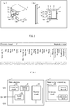
- Fig. 1 illustrates a vehicular static eliminating device 1 in accordance with Embodiment 1 of the present invention.
- (a) of Fig. 1 is a view illustrating an appearance of the vehicular static eliminating device 1.
- (b) of Fig. 1 is a cross-sectional view schematically illustrating a configuration of the vehicular static eliminating device 1. Note that (b) of Fig. 1 also illustrates a static elimination target spot S.
- the vehicular static eliminating device 1 includes a negative ion generating device (negative ion generating section) 2 and a guide device 10 including no air blowing device.
- the negative ion generating device 2 is a device configured to generate negative ions.
- the negative ion generating device 2 has a housing 3 provided with a projecting needle-like discharge electrode 4.
- a counter electrode 5 is provided around the discharge electrode 4.
- the discharge electrode 4 forms an electric field between the discharge electrode 4 and the counter electrode 5, and negative ions are generated from a tip of the discharge electrode 4.
- Fig. 1 shows a needle-like electrode as an example of the discharge electrode 4. Note, however, that the discharge electrode 4 can alternatively be a brush-like electrode or a triangular electrode.
- the housing 3 houses therein a discharge substrate (not illustrated) configured to control the discharge electrode 4 and the counter electrode 5.
- the discharge substrate is connected with a main substrate 30 described later (see Fig. 3 ).
- the guide device 10 guides negative ions generated by the negative ion generating device 2 and releases the negative ions from emission ports 11 toward the static elimination target spot S.
- the guide device 10 includes a guide member 13 and tip-shaped parts 14.
- the guide member 13 defines a passage for negative ions and has, on a front wall 13a thereof provided on a downstream side in a direction in which the negative ions flow, a plurality of openings serving as the emission ports 11 of the guide device 10. According to the configuration of Embodiment 1, since the openings of the guide member 13 serve as the emission ports 11 of the guide device 10, those openings may also be expressed as the emission ports 11 of the guide member 13.
- Fig. 1 illustrates the guide member 13 which is configured to have a cube-shaped appearance. Note, however, that the guide member 13 can be, for example, cylindrical or hexagonal column-shaped.
- the guide member 13 is made of a resin which is easily negatively charged in such a triboelectric series as illustrated in Fig. 2 , such as acrylonitrile butadiene styrene (ABS) or polypropylene (PP).
- Fig. 2 is a view showing a triboelectric series of typical materials. Resins which are easily negatively charged refer to resins enclosed by a broken line in Fig. 2 and including polypropylene (PP) and resins located on the right side of polypropylene (PP).
- the guide member 13 which is made of a resin which is easily negatively charged is negatively charged and retains negative electric charges.
- the tip-shaped parts 14 are provided (i) in parts defining the emission ports 11 and (ii) in proximity to the static elimination target spot S.
- the expression "provided in proximity” is rephrased as follows. Specifically, the tip-shaped parts 14 are positioned relative to the static elimination target spot S so that the tip-shaped parts 14 can discharge, by corona discharge, negative electric charges, which have accumulated on the guide member 13, to the static elimination target spot S which is more positively charged than the tip-shaped parts 14. This allows the tip-shaped parts 14 to discharge, by corona discharge, negative electric charges, which have accumulated on the guide member 13, to the static elimination target spot S which is positively charged.
- Each of the tip-shaped parts 14 has a tip such as a protrusion, a corner, or a point and (ii) has a shape which easily causes corona discharge.
- negative electric charges supported by the guide member 13 can be discharged, by corona discharge, from points of the tip-shaped parts 14 to the static elimination target spot S.
- the static elimination target spot S is positively charged, by bringing the tip-shaped parts 14 into proximity to the static elimination target spot S, negative electric charges accumulating on the guide member 13 are attracted to positive electric charges of the static elimination target spot S, so that corona discharge occurs.
- corners of parts defining the emission ports 11 are pointed. These pointed corners serve as the tip-shaped parts 14.
- Fig. 1 illustrates a configuration in which the negative ion generating device 2 is provided inside the guide member 13. Note, however, that the negative ion generating device 2 can be connected with the guide member 13 so that negative ions generated by the negative ion generating device 2 can be supplied to inside the guide member 13.
- the distance from the tip of the discharge electrode 4 to the front wall 13a is preferably, for example, 10 mm to 30 mm.
- Fig. 3 is a circuit diagram illustrating an electric circuit configuration of the vehicular static eliminating device 1.
- a protection circuit 21, a constant voltage circuit 22, a switch circuit 23, and a booster circuit 24 are provided on the main substrate 30.
- a conversion circuit 25 is provided on the discharge substrate described earlier. The conversion circuit 25 can alternatively be provided on the main substrate 30.
- Fig. 3 illustrates a configuration in which a single negative ion generating device 2 is connected to the main substrate 30. Note, however, that, in a case where a plurality of vehicular static eliminating devices 1 are placed, a plurality of negative ion generating devices 2 are connected to the main substrate 30.
- Fig. 4 is a view describing a static elimination operation carried out in the vehicular static eliminating device 1.
- the negative ions generated are guided to the emission ports 11 by the guide member 13 of the guide device 10 and released from the emission ports 11 to the static elimination target spot S.
- the negative ions released neutralize positive electric charges, accumulating on the static elimination target spot S, so as to eliminate static electricity from the static elimination target spot S or to negatively charge the static elimination target spot S.
- Negative ions have the highest concentration near the emission ports 11 and have a lower concentration as the negative ions are away from the emission ports 11.
- a static elimination capability of negative ions depends on a concentration of negative ions to be released.
- the emission ports 11 which are provided closer to the static elimination target spot S allow negative ions to more effectively carry out static elimination.
- corona discharge which occurs in the tip-shaped parts 14, more easily occurs in a case where the tip-shaped parts 14 are closer to the static elimination target spot S.
- the emission ports 11 provided with the tip-shaped parts 14 are provided closer to the static elimination target spot S, it is possible to more effectively cause corona discharge.
- corona discharge has a limit of occurrence.
- the shortest distance at which respective centers of the emission ports 11 and the static elimination target spot S are spaced is more than 100 mm, corona discharge does not occur.
- the shortest distance at which the respective centers of the emission ports 11 and the static elimination target spot S are spaced needs to be not more than 100 mm, which is the limit of occurrence of corona discharge.
- the following distance is defined as the shortest distance between the respective centers of the emission ports 11 and the static elimination target spot S.
- the distance thus defined includes, for example, a case where the emission ports 11 are provided so as to be inclined with respect to the static elimination target spot S.
- the distance is most preferably 20 mm.
- the distance which is 20 mm brings about the greatest static elimination effect. This makes it possible to more greatly reduce a positive electric potential of the static elimination target spot S, so that the positive electric potential can be made closer to zero or a negative electric potential lower than zero.
- a static elimination effect is reduced as the distance is away from a peak of 20 mm. Specifically, in a case where the distance is not more than 100 mm, a static elimination effect is enhanced because an effect, brought about by corona discharge, of rectifying a problem of prevention of release of negative ions (also referred to as a "corona discharge effect”) allows negative ions to be released in a larger amount as the distance is closer to 20 mm.
- the distance which is 20 mm makes it possible to bring about the greatest static elimination effect while most perfectly balancing a corona discharge effect and a range of release of negative ions with each other.
- the distance is most preferably 20 mm. Note, however, that it has also been confirmed that the distance which falls within the range of 20( ⁇ 2) mm (i.e., 18 mm to 22 mm) effectively achieves the effect described earlier. Thus, the distance which falls within the range of 18 mm to 22 mm makes it possible to bring about a great static elimination effect.
- a phenomenon such that a static elimination effect starts to be gradually reduced in a case where the respective centers of the emission ports 11 and the static elimination target spot S are spaced at a distance of less than 20 mm occurs not only in a type including no air blowing device (e.g., the vehicular static eliminating device 1) but also in a type including an air blowing device (e.g., a vehicular static eliminating device 6 described later (see Fig. 10 )).
- Fig. 5 illustrates a static elimination range in a case where the vehicular static eliminating device 1 is provided so as to face the static elimination target spot S.
- (a) of Fig. 5 is a lateral view of the static elimination range.
- (b) of Fig. 5 is a plan view of the static elimination range.
- the static elimination range is a limited circular range whose center is a location at which the vehicular static eliminating device 1 is placed. From the static elimination target spot S included in the above static elimination range, static electricity is eliminated.
- Fig. 6 is a view showing an example of how the vehicular static eliminating device 1 is placed with respect to vehicle glass 35.
- the vehicle glass 35 is, for example, a windshield, side glass, or rear glass.
- a placement surface 36 on which the vehicular static eliminating device 1 is placed is a plate-like design component such as a dashboard, a front pillar, a rear pillar, or an inner panel of a side door.
- the vehicular static eliminating device 1 is placed so that (i) the tip of the discharge electrode 4 extends from inside a vehicle body toward a peripheral edge part of the vehicle glass 35 and (ii) a direction in which the discharge electrode 4 protrudes is inclined with respect to the vehicle glass 35.
- the vehicular static eliminating device 1 which is configured to include no air blowing device and is small in size, provides a feeling of strangeness in a case where the vehicular static eliminating device 1 is placed in the vehicle so that the discharge electrode 4 is provided so as to face the front of the vehicle glass 35.
- the vehicular static eliminating device 1 can be placed in the vehicle without a feeling of strangeness.
- Fig. 7 is a view showing another example of how the vehicular static eliminating device 1 is placed with respect to the vehicle glass 35.
- the placement surface 36 is provided with a recess 36a which is made to fit external dimensions of the vehicular static eliminating device 1, and the vehicular static eliminating device 1 is embedded in the recess 36a so that the placement surface 36 and the front wall 13a are flush with each other.
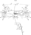
- Fig. 8 is a view showing an example of a place at which to place the vehicular static eliminating device 1.
- the vehicular static eliminating device 1 includes vehicular static eliminating devices 1 placed at respective right and left corners of a dashboard 38 and vehicular static eliminating devices 1 placed on respective right and left front pillars 31.
- the vehicular static eliminating device 1 further includes vehicular static eliminating devices 1 which are placed on respective inner panels 32 of right and left side doors 40 and on the front side in a traveling direction of the vehicle on respective lower end sides of openings 40a.
- the vehicular static eliminating device 1 further includes a vehicular static eliminating device 1 which is placed inside a cover 41a of a rearview mirror 41 so as to be in proximity to the windshield 37 while facing an upper part of a center of the windshield 37.
- the vehicular static eliminating device 1 can include, in addition to the above vehicular static eliminating devices 1, a vehicular static eliminating device 1 placed on a roof (not illustrated), a vehicular static eliminating device 1 placed on rear window glass (not illustrated), a vehicular static eliminating device 1 placed on a center pillar (not illustrated), a vehicular static eliminating device 1 placed in a grip part of a door handle (not illustrated), and/or a vehicular static eliminating device 1 placed in a bent part of an undercover (not illustrated).
- a vehicle is charged with positive static electricity by, for example, (i) an external factor including a vehicle body traveling (ii) and the vehicle body being insulated from a road surface by a wheel made of an insulating material.
- Fig. 9 illustrates a confirmatory experiment on a static elimination effect.
- (a) of Fig. 9 illustrates the shape of vehicle glass used in the confirmatory experiment.
- (b) of Fig. 9 is a configuration diagram schematically illustrating an experimental system used to carry out the confirmatory experiment.
- the vehicle glass was the side glass 39 having a thickness t of 3 mm and having a shape of a trapezoid having an upper side of 600 mm, a lower side of 800 mm, and a height of 465 mm.
- Such side glass 39 was placed in the experimental system illustrated in (b) of Fig. 9 .
- two electrostatic measuring instruments 45 Electrostatic Fieldmeter FMX-004 (manufactured by SIMCO)) were provided so that a speed of static elimination carried out on each of a front surface and a back surface of the side glass 39 was measurable.
- the electrostatic measuring instruments 45 each carried out measurement at a location 100 mm away from a lower end of a peripheral edge part of the side glass 39. Furthermore, on a side on which one of the electrostatic measuring instruments 45, which one was used to carry out measurement with respect to the front surface of the side glass 39, was located, a positive ion generating device 42 and a fan 44 were provided via a paper duct 43.
- the vehicular static eliminating device 1 was placed at a distance of 20 mm from the back surface of the side glass 39, whose front surface and back surface were constantly charged in an amount of +1 kV to +2 kV, while a direction in which the discharge electrode 4 inside the vehicular static eliminating device 1 protrudes was inclined at 45° with respect to a surface of the side glass 39.
- the vehicular static eliminating device 1 thus placed was turned on, and then an amount in which the front surface and the back surface of the side glass 39 were charged while the vehicular static eliminating device 1 was being on was determined.
- the vehicular static eliminating device 1 was placed so that (i) a line extending from the tip of the discharge electrode 4 and indicated by a dotted and dashed line in Fig. 9 and (ii) a line connecting the electrostatic measuring instruments 45 intersected each other in the side glass 39.
- An amount in which the front surface and the back surface of the side glass 39 were charged was changed from approximately 0 to -1.0 kV. Then, in a case where the vehicular static eliminating device 1 was turned off, the amount was reset to an initial value of +1 kV to +2 kV after the elapse of approximately 60 seconds from the turning-off of the vehicular static eliminating device 1.
- Fig. 10 is a cross-sectional view schematically illustrating a configuration of a vehicular static eliminating device 6 in accordance with Embodiment 2 of the present invention.
- the vehicular static eliminating device 6 includes a guide device 15 with which the guide device 10 is replaced and which includes an air blowing device 17.
- the guide device 15 includes a guide pipe (guide member) 16 with which the guide member 13 is replaced.
- the guide pipe 16 has (i) an opening which is provided at a first end thereof and to which the air blowing device 17 is connected and (ii) an opening which is provided at a second end thereof and serves as an emission port 11 from which negative ions are released.
- the guide pipe 16 is provided so as to face a static elimination target spot S.
- a current of air which flows through the guide pipe 16 to the emission port 11 is produced.
- Fig. 10 illustrates the guide pipe 16 which is configured to branch into two. Note, however, that the guide pipe 16 can alternatively branch into three or more, or the guide pipe 16 does not need to branch.
- a negative ion generating device 2 is connected to the guide pipe 16 so as to allow negative ions generated by the negative ion generating device 2 to be supplied to a current of air flowing through the guide pipe 16.
- the negative ion generating device 2 can be provided downstream from the air blowing device 17 in a direction in which negative ions flow. Note, however, that, in a case where the guide pipe 16 branches, the negative ion generating device 2 is provided upstream from a place at which the guide pipe 16 branches.
- the guide pipe 16 is also made of a resin which is easily negatively charged in a triboelectric series. Corners of a part defining the emission port 11 of the guide pipe 16 are pointed. These pointed corners serve as tip-shaped parts 14.
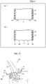
- Fig. 11 is an enlarged view of an emission port 11 part of the guide device 15 of the vehicular static eliminating device 6.
- (a) of Fig. 11 shows an example of the tip-shaped parts 14 formed of corners.
- (b) of Fig. 11 shows an example of the tip-shaped parts 14 formed of tips.
- the tip-shaped parts 14 are formed by giving points to corners of an end surface of an end opening serving as the emission port 11 of the guide pipe 16.
- the tip-shaped parts 14 can alternatively be formed by providing the end surface of the end opening serving as the emission port 11 of the guide pipe 16 with many tips.
- the tip-shaped parts 14 are placed in proximity to the static elimination target spot S.
- the vehicular static eliminating device 6 thus configured, negative ions generated by the negative ion generating device 2 are guided through the guide pipe 16 to the emission port 11 by a current of air generated by the air blowing device 17, so that the negative ions are released from the emission port 11 to the static elimination target spot S.
- negative electric charges of the guide pipe 16 are discharged, by corona discharge, to the static elimination target spot S which is positively charged, negative electric charges of the emission port 11 of the guide pipe 16 are greatly reduced.
- negative ions which are being guided to the emission port 11 are divided into two groups in the middle of the guide pipe 16, so that the two groups of negative ions are released to respective two static elimination target spots S.
- Fig. 12 is a view showing an example of how the vehicular static eliminating device 6 is placed.
- the vehicular static eliminating device 6 has two emission ports 11.
- One of the two emission ports 11 is provided so as to extend from a dashboard 38 toward a peripheral edge part of a windshield 37, and the other of the two emission ports 11 is provided so as to extend from an inner panel 32 of a side door 40 toward a peripheral edge part of side glass 39.
- the guide pipe 16 can be branched into three so that a third emission port 11 is placed so as to extend from a front pillar 31 toward the peripheral edge part of the windshield 37.
- Fig. 12 illustrates the vehicular static eliminating device 6 without concealing the vehicular static eliminating device 6 in the dashboard 38 and the inner panel 32 of the side door 40. Note, however, that the vehicular static eliminating device 6 is actually embedded within the dashboard 38 and the inner panel 32 of the side door 40, and only parts of the vehicular static eliminating device 6 in which parts the respective emission ports 11 are provided are exposed from respective openings provided in the dashboard 38 and the inner panel 32 of the side door 40.
- Fig. 12 merely illustrates a configuration in which the vehicular static eliminating device 6 is provided on the passenger seat side. Note, however, that the vehicular static eliminating device 6 can also be similarly provided on the driver's seat side.
- the guide device 15 thus configured to include an air blowing device makes it possible to, without causing generated negative ions to remain in the guide pipe 16, efficiently guide the negative ions to the emission ports 11 and release the negative ions.
- corona discharge which occurs in the tip-shaped parts 14, more easily occurs in a case where the tip-shaped parts 14 are closer to a static elimination target spot S.
- an emission port 11 provided with the tip-shaped parts 14 is provided closer to the static elimination target spot S, it is possible to more effectively cause corona discharge.
- the shortest distance between a center of the emission port 11 which is provided with the tip-shaped parts 14 and the static elimination target spot S is preferably not more than 100 mm, and more preferably 20 mm.
- Fig. 13 is a cross-sectional view schematically illustrating a configuration of a vehicular static eliminating device 7 in accordance with Embodiment 3 of the present invention.
- Fig. 14 is an enlarged view of an emission port 11 part of a guide device 18 of the vehicular static eliminating device 7.
- the vehicular static eliminating device 7 is configured to include an electrostatic induction member 19 provided on a side of the vehicular static eliminating device 6 in accordance with Embodiment 2 on which side an end having the emission port 11 of the guide pipe 16 is provided.
- the vehicular static eliminating device 7 includes the guide device 18 with which the guide device 15 is replaced and which includes the electrostatic induction member 19.
- Fig. 13 illustrates a configuration in which the electrostatic induction member 19 is formed of an electrically conductive sheet metal ring (e.g., an aluminum cylinder) and is in contact with the guide pipe 16. Note, however, that the electrostatic induction member 19 can be in non-contact with the guide pipe 16 provided that a distance between the electrostatic induction member 19 and the guide pipe 16 allows negative electric charges having accumulated on the guide pipe 16 to move to the electrostatic induction member 19.
- an opening located at an end of the guide pipe 16 serves as the emission port 11 of the guide device 18 and is provided with tip-shaped parts 14.
- the electrostatic induction member 19 is located upstream from the opening, located at the end of the guide pipe 16, in a direction in which negative ions flow.
- Embodiment 3 shows, as an example, a configuration in which the electrostatic induction member 19 is provided in combination with the air blowing device 17.
- the electrostatic induction member 19 can alternatively be provided to the emission ports 11 of the guide member 13 of the guide device 10 of Embodiment 1, which guide device 10 includes no air blowing device 17.
- the electrostatic induction member 19 is preferably provided as close as possible to an end of the guide pipe 16 at which end the emission port 11 is located. This makes it possible to release negative ions, attracted to the emission port 11, while giving momentum to the negative ions without causing the negative ions to remain in the guide pipe 16.
- Such an electrostatic induction member 19 can be formed of, for example, an electrically conductive sheet metal ring as described earlier.
- the electrostatic induction member 19 which is formed of the electrically conductive sheet metal ring can be attached to an end of the guide pipe 16, at which end the emission port 11 is located, by, for example, (i) integrally-molding the electrostatic induction member 19 with the end, (ii) pressing the electrostatic induction member 19 into the end, or (iii) adhering the electrostatic induction member 19 to the end with use of, for example, an electrically conductive adhesive.
- the electrostatic induction member 19 can alternatively be prepared by, for example, winding aluminum adhesive tape around the end.
- the electrostatic induction member 19 can be configured to be (i) made of a coated film obtained by applying electrically conductive paint (discharge paint) to the emission port 11 side of the guide pipe 16 and (ii) provided with the tip-shaped parts 14 which cause corona discharge by a tip shape formed on the coated film.
- the electrically conductive paint can be, for example, metallic paint or carbon paint.
- the electrostatic induction member 19 which is formed of the electrically conductive sheet metal ring is hereinafter referred to as an electrically conductive sheet metal ring 19.
- Fig. 15 is an enlarged view of an emission port 11 part of a guide device 20 of a vehicular static eliminating device 8 in accordance with Embodiment 4 of the present invention.
- an electrically conductive sheet metal ring 19 protrudes toward a static elimination target spot S beyond an opening located at an end of a guide pipe 16.
- an end of the electrically conductive sheet metal ring 19 which end thus protrudes serves as an emission port 11 of the guide device 20.
- Tip-shaped parts 14 are provided at the protruding end of the electrically conductive sheet metal ring 19 so as to be in proximity to the static elimination target spot S.
- Negative electric charges of the guide pipe 16 are guided to the electrically conductive sheet metal ring 19, so that corona discharge is easily carried out from the tip-shaped parts 14 of the electrically conductive sheet metal ring 19 to the static elimination target spot S which is positively charged. This makes it possible to stably release negative ions, flowing through the guide pipe 16, with higher efficiency without causing the negative ions to remain in the guide pipe 16.
- Fig. 16 which shows a variation of the vehicular static eliminating device 8, is an enlarged view of an emission port 11 part of a guide device 20'.
- an electrically conductive sheet metal ring 19 is provided so as to be flush with an opening located at an end of a guide pipe 16.
- an end of the electrically conductive sheet metal ring 19 which is provided so as to be flush with the opening located at the end of the guide pipe 16 is also provided with tip-shaped parts 14 for causing corona discharge.
- Fig. 17 is a view schematically illustrating a configuration of a vehicular static eliminating device 9 in accordance with Embodiment 5 of the present invention and showing an example of how the vehicular static eliminating device 9 is placed with respect to vehicle glass 35.
- the vehicular static eliminating device 9 is configured to include an electrically conductive sheet metal ring 19 provided on a side of the vehicular static eliminating device 1 in accordance with Embodiment 1 on which side an end having the emission ports 11 of the guide member 13 is provided.
- the electrically conductive sheet metal ring 19 also functions as an extension guide member for extending an outlet of the guide member 13 to a static elimination target spot S.
- the emission ports 11 of the vehicular static eliminating device 9 can be easily made close to the static elimination target spot S.
- the emission ports 11 of the vehicular static eliminating device 9 can be easily made close to the static elimination target spot S.
- commonality of structures except the electrically conductive sheet metal ring 19 and adjusting the length of the electrically conductive sheet metal ring 19 in accordance with a distance to the static elimination target spot S it is possible to easily carry out corona discharge. It is also possible to reduce cost while effectively carrying out static elimination.
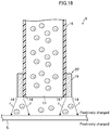
- Fig. 18 is a view showing an example of a vehicle to which the present invention is applicable.
- a wheel 62 is made of an insulating material (or a material having a low electric conductivity), such as rubber, so that a vehicle body 63 is insulated from a road surface.
- positive static electric charges are generated by electrical action that accompanies, for example, friction between the vehicle body 63 and an air flowing outside the vehicle or friction between the vehicle body 63 and an airflow flowing through an air duct.
- the positive static electric charges thus generated accumulate on the vehicle body 63.
- Air is ordinarily positively charged.
- the air and the vehicle body 63 on which positive static electric charges accumulate repel each other.
- intake air and the intake passage of the air intake device of the driving force generating device on which intake passage positive static electric charges accumulate also repel each other.
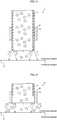
- Fig. 19 is graphs showing measurement results of flow velocity distribution in a direction perpendicular to a positively charged surface of a model vehicle and flow velocity distribution in a direction perpendicular to an uncharged surface of the model vehicle.
- the vertical axis shows a distance from the surface of the model vehicle
- the horizontal axis shows a ratio (U/U ⁇ ) of (a) a flow velocity U measured for each distance from the model vehicle to (b) a flow velocity U ⁇ of air flowing on the surface of the model vehicle.
- Square dots show measured values of a flow velocity of the air flowing on the positively charged surface of the model vehicle
- rhombus dots show measured values of a flow velocity of the air flowing on the uncharged surface of the model vehicle.
- a thickness of a boundary layer i.e., a distance from the surface of model vehicle at which surface the ratio U/U ⁇ is substantially 1 of a case where the surface of the model vehicle is positively charged is larger than that of a case where the surface of the model vehicle is not positively charged.
- an influence by positive static electric charges can be effectively reduced by eliminating static electricity from such a point at which air flowing along a surface of an outer wall of the vehicle body is easily separated from the surface and/or a point at which intake air of the driving force generating device is easily separated from a surface of the intake air passage wall.
- An airflow flowing along a surface of the vehicle body 63 has a tendency to be separated from the surface of the vehicle body 63 at, for example, such specific points as described below. Specifically, when the vehicle body 63 is seen from the front side, the airflow is separated from the surface of the vehicle body 63 mainly at a point where an outer surface of the vehicle body 63 is inwardly bent. More specifically, on both right and left sides of the vehicle body 63, the airflow is separated from the surface of the vehicle body 63 at points where the outer surface is bent so that the width of the vehicle is narrowed. In the hood or a roof, the airflow is separated from the surface of the vehicle body 63 at a point where the outer surface is downwardly bent.
- the airflow is separated from the surface of the vehicle body 63 at a bent part located between (a) a part of the vehicle which part is inclined so that the vehicle has a lower height as the vehicle extends further backward and (b) a part of the vehicle which part is horizontal to a road surface or at a bent part located between (c) a part of the vehicle which part is horizontal to a road surface and (d) a part of the vehicle which part is inclined so that the vehicle has a higher height as the vehicle extends further backward.
- the airflow also has a tendency to be separated from the surface of the vehicle body 63 at a point partially protruding to an outside of the vehicle body 63 or a point having a step. An airflow flowing along a surface of the vehicle body 63 is thus separated from the surface of the vehicle body 63 at such specific points as described earlier.
- a back wall surface of a part of a body outer wall is regarded as a static elimination target spot S and static electricity is eliminated from the static elimination target spot S.
- the static elimination target spot S is negatively charged. This makes it possible to effectively restrain the airflow from being separated from the surface of the body outer wall.
- an outer wall surface of a part of an intake air passage wall made of a resin, the part having a shape which makes it easy for intake air to be separated from an inner surface of the intake air passage wall, is regarded as a static elimination target spot S and static electricity is eliminated from the static elimination target spot S.
- This makes it possible to effectively restrain a flow of intake air from being separated from the inner surface of the intake air passage wall, and consequently to take in intake air with higher efficiency.
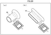
- FIG. 20 are each an explanatory view illustrating (i) an intake air introduction pipe 66 to an air cleaner, which is a part of an air intake device of a driving force generating device of a vehicle and (ii) the vehicular static eliminating device 1 illustrated in Fig. 1 and provided near the intake air introduction pipe 66 so as to be in proximity to the intake air introduction pipe 66.
- a place where a flow of intake air is separated from an inner surface of an intake air passage wall of the intake air introduction pipe 66 is indicated by an ellipse (dotted and dashed line).
- the vehicular static eliminating device 1 is provided in proximity to the intake air introduction pipe 66 so as to release negative ions to an outer wall of an intake air passage near the ellipse.
- the intake air introduction pipe 66 is shown by a perspective view, whereas the vehicular static eliminating device 1 is shown by a cross-sectional view for convenience.
- Fig. 18 shows, as an example of a vehicle to be provided with any of the vehicular static eliminating devices 1 and 6 to 9 described earlier, a vehicle whose wheel 62 is made of an insulating material such as rubber and whose vehicle body 63 is insulated from a road surface.
- the vehicle can alternatively be a train whose iron wheel runs on a rail.
- the vehicle includes a vehicle on which positive static electric charges accumulate by, for example, an external factor including travel of a vehicle body.
- a vehicular static eliminating device is (i) provided in a vehicle on which positive static electric charges accumulate by, for example, an external factor including travel of a vehicle body which is insulated from a road surface and (ii) configured to eliminate static electricity from a static elimination target spot in the vehicle, the static elimination target spot being predetermined and positively charged, or to negatively charge the static elimination target spot
- the vehicular static eliminating device including: a negative ion generating section; and a guide device configured to guide negative ions generated by the negative ion generating section, and release the negative ions from an emission port to the static elimination target spot
- the guide device including: a guide member defining a passage through which to guide the negative ions, the guide member being made of a resin which is easily negatively charged in a triboelectric series; and a tip-shaped part configured to discharge, by corona discharge, negative electric charges, which have accumulated on the guide member, to the static elimination target spot,
- a vehicular static eliminating device can be configured such that, in the first aspect of the present invention, the static elimination target spot is a back wall surface of a part of a body outer wall of the vehicle, the part having a shape which makes it easy for air flowing along a surface of the body outer wall to be separated from the surface.
- a vehicular static eliminating device can be configured such that, in the first aspect of the present invention, the static elimination target spot is an outer wall surface of a part of an intake air passage wall, made of resin, of a driving force generating device of the vehicle, the part having a shape which makes it easy for intake air to be separated from an inner surface of the intake air passage wall.
- a vehicular static eliminating device can be configured such that, in any one of the first through third aspects of the present invention, the guide device includes an air blowing device configured to blow the negative ions to the emission port.
- a vehicular static eliminating device can be configured such that, in any one of the first through fourth aspects of the present invention, the guide device includes an electrostatic induction member provided on a side of the guide member on which side an outlet for the negative ions is provided.
- a vehicular static eliminating device can be configured such that, in the fifth aspect of the present invention, the electrostatic induction member has a static elimination target spot side end which is located so as to be at least flush with the outlet of the guide member or closer to the static elimination target spot than the outlet of the guide member and which is provided with the tip-shaped part for causing the corona discharge.
- a vehicular static eliminating device can be configured such that, in the fifth or sixth aspect of the present invention, the electrostatic induction member is formed of an electrically conductive sheet metal ring, and the electrostatic induction member is integrally-molded with, pressed into, or adhered to the outlet of the guide member.
- a vehicular static eliminating device can be configured such that, in the fifth aspect of the present invention, the electrically conductive sheet metal ring also functions as an extension guide member for extending the outlet of the guide member to the static elimination target spot.
- a vehicular static eliminating device can be configured such that, in the sixth aspect of the present invention, the electrostatic induction member is (i) made of a coated film obtained by applying electrically conductive paint to the outlet of the guide member and (ii) provided with the tip-shaped part for causing the corona discharge by a tip shape formed on the coated film.
- a vehicular static eliminating device can be configured such that, in any one of the first through ninth aspects of the present invention, the shortest distance between a center of the emission port of the guide device and the static elimination target spot is not more than 100 mm.
- a vehicular static eliminating device can be configured such that, in any one of the first through ninth aspects of the present invention, the corona discharge is carried out with respect to the static elimination target spot which is spaced the shortest distance of 100 mm away from a center of the emission port of the guide device.
- a vehicular static eliminating device can be configured such that, in the tenth aspect of the present invention, the shortest distance between the center of the emission port of the guide device and the static elimination target spot is 20 mm.
- a vehicular static eliminating device can be configured such that, in the tenth aspect of the present invention, a static elimination effect on the static elimination target spot which is spaced the shortest distance of 20 mm away from the center of the emission port of the guide device reaches a peak.
- a vehicle in a twelfth aspect of the present invention, includes a vehicular static eliminating device recited in any one of the first through eleventh aspects of the present invention.
Landscapes
- Engineering & Computer Science (AREA)
- Mechanical Engineering (AREA)
- Chemical & Material Sciences (AREA)
- Combustion & Propulsion (AREA)
- Physics & Mathematics (AREA)
- Plasma & Fusion (AREA)
- General Engineering & Computer Science (AREA)
- Health & Medical Sciences (AREA)
- General Health & Medical Sciences (AREA)
- Toxicology (AREA)
- Transportation (AREA)
- Elimination Of Static Electricity (AREA)
Claims (12)
- Vorrichtung (1, 6, 7, 8, 9) zur Beseitigung von Fahrzeugstatik, (i) die in einem Fahrzeug (61) bereitgestellt ist, an dem sich, zum Beispiel durch einen äußeren Faktor, einschließlich der Bewegung einer Fahrzeugkarosserie, die von einer Straßenoberfläche isoliert ist, positive statische elektrische Ladungen ansammeln und (ii) die gestaltet ist zum Beseitigen statischer Elektrizität von einem Statikbeseitigungszielpunkt (S) in dem Fahrzeug, wobei der Statikbeseitigungszielpunkt vorbestimmt und positiv geladen ist, oder zum negativen Aufladen des Statikbeseitigungspunkts,
wobei die genannte Vorrichtung zur Beseitigung von Fahrzeugstatik aufweist:einen Negativ-Ionen-Erzeugungsabschnitt (2); undeine Führungsvorrichtung (10, 15, 18, 20, 20'), die gestaltet ist zum Führen negativer Ionen, die von dem Negativ-Ionen-Erzeugungsabschnitt erzeugt werden, und zum Freisetzen der negativen Ionen aus einer Emissionsöffnung (11) zu dem Statikbeseitungszielpunkt,wobei die Führungsvorrichtung beinhaltet:ein Führungselement (13, 16), das einen Durchgang definiert, durch den die negativen Ionen geführt werden, wobei das Führungselement aus einem Harz hergestellt ist, das in einer triboelektrischen Reihe leicht negativ geladen wird;dadurch gekennzeichnet, dass die genannte Vorrichtung zur Beseitigung von Fahrzeugstatik ein spitzenförmiges Teil (14) aufweist, das gestaltet ist zum Entladen negativer elektrischer Ladungen, die sich an dem Führungselement angesammelt haben, durch Koronaentladung zu dem Statikbeseitigungszielpunkt, wobei das spitzenförmige Teil in einem Teil, das die Emissionsöffnung definiert, und in der Nähe des Statikbeseitigungszielpunkts bereitgestellt ist. - Vorrichtung zur Beseitigung von Fahrzeugstatik nach Anspruch 1, wobei die Führungsvorrichtung eine Luftblasvorrichtung (17) beinhaltet, die zum Blasen der negativen Ionen zur Emissionsöffnung gestaltet ist.
- Vorrichtung zur Beseitigung von Fahrzeugstatik nach Anspruch 1 oder 2, wobei die Führungsvorrichtung ein Influenzelement (19) beinhaltet, das auf einer Seite des Führungselements bereitgestellt ist, wobei auf dieser Seite ein Auslass für die negativen Ionen bereitgestellt ist.
- Vorrichtung zur Beseitigung von Fahrzeugstatik nach Anspruch 3, wobei das Influenzelement ein Ende auf Seite des Statikbeseitigungszielpunkts aufweist, das so angeordnet ist, dass es mindestens bündig mit dem Auslass des Führungselements oder näher an dem Statikbeseitigungszielpunkt ist als der Auslass des Führungselements, und das mit dem spitzenförmigen Teil zum Bewirken der Koronaentladung versehen ist.
- Vorrichtung zur Beseitigung von Fahrzeugstatik nach Anspruch 3 oder 4, wobei das Influenzelement aus einem elektrisch leitenden Blechring gebildet ist und das Influenzelement an bzw. in den Auslass des Führungselements angeformt, eingepresst oder angefügt ist.
- Vorrichtung zur Beseitigung von Fahrzeugstatik nach Anspruch 5, wobei der elektrisch leitende Blechring auch als eine Führungselementverlängerung zum Verlängern des Auslasses des Führungselements zu dem Statikbeseitigungszielpunkt dient.
- Vorrichtung zur Beseitigung von Fahrzeugstatik nach Anspruch 4, wobei das Influenzelement (i) aus einer aufgetragenen Schicht hergestellt ist, die durch Auftragen elektrisch leitender Farbe auf den Auslass des Führungselements erhalten wird, und (ii) mit dem spitzenförmigen Teil zum Bewirken der Koronaentladung durch eine auf der aufgetragenen Schicht gebildete Spitzenform versehen ist.
- Vorrichtung zur Beseitigung von Fahrzeugstatik nach einem der Ansprüche 1 bis 7, wobei der kürzeste Abstand zwischen einem Mittelpunkt der Emissionsöffnung der Führungsvorrichtung und dem Statikbeseitigungszielpunkt nicht mehr als 100 mm beträgt.
- Vorrichtung zur Beseitigung von Fahrzeugstatik nach Anspruch 8, wobei der kürzeste Abstand zwischen dem Mittelpunkt der Emissionsöffnung der Führungsvorrichtung und dem Statikbeseitigungszielpunkt 20 mm beträgt.
- Fahrzeug mit einer Vorrichtung zur Beseitigung von Fahrzeugstatik nach einem der Ansprüche 1 bis 9.
- Fahrzeug nach Anspruch 10, wobei der Statikbeseitigungszielpunkt eine Rückwandfläche eines Teils einer Karosserieaußenwand des Fahrzeugs ist, wobei das Teil eine Form hat, die es an einer Oberfläche der Karosserieaußenwand entlangströmender Luft leicht macht, von der Oberfläche getrennt zu werden.
- Fahrzeug nach Anspruch 10, wobei der Statikbeseitigungszielpunkt eine Außenwandfläche eines Teils einer aus Harz hergestellten Ansaugluftkanalwand einer Antriebskrafterzeugungsvorrichtung des Fahrzeugs ist, wobei der Teil eine Form hat, die es Ansaugluft leicht macht, von einer Innenfläche der Ansaugluftkanalwand getrennt zu werden.
Applications Claiming Priority (1)
| Application Number | Priority Date | Filing Date | Title |
|---|---|---|---|
| JP2018130179A JP7050600B2 (ja) | 2018-07-09 | 2018-07-09 | 車両用除電装置および車両 |
Publications (2)
| Publication Number | Publication Date |
|---|---|
| EP3594069A1 EP3594069A1 (de) | 2020-01-15 |
| EP3594069B1 true EP3594069B1 (de) | 2020-11-11 |
Family
ID=67184782
Family Applications (1)
| Application Number | Title | Priority Date | Filing Date |
|---|---|---|---|
| EP19183966.1A Active EP3594069B1 (de) | 2018-07-09 | 2019-07-02 | Vorrichtung zur beseitigung von fahrzeugstatik und fahrzeug |
Country Status (4)
| Country | Link |
|---|---|
| US (1) | US10988093B2 (de) |
| EP (1) | EP3594069B1 (de) |
| JP (1) | JP7050600B2 (de) |
| CN (1) | CN110696758A (de) |
Families Citing this family (4)
| Publication number | Priority date | Publication date | Assignee | Title |
|---|---|---|---|---|
| JP7571715B2 (ja) * | 2021-12-03 | 2024-10-23 | トヨタ自動車株式会社 | 自動車のスマートキーシステム |
| CN114340119B (zh) * | 2021-12-28 | 2025-02-14 | 江苏西南智能纺织有限公司 | 一种应用于纺织品仓库的静电消除装置 |
| JP7586131B2 (ja) * | 2022-05-09 | 2024-11-19 | トヨタ自動車株式会社 | 車両 |
| JP7708052B2 (ja) | 2022-09-13 | 2025-07-15 | トヨタ自動車株式会社 | 車両 |
Family Cites Families (13)
| Publication number | Priority date | Publication date | Assignee | Title |
|---|---|---|---|---|
| JPS5552932A (en) | 1978-10-16 | 1980-04-17 | Toshiba Corp | Head for sludge concentration meter |
| JPS5675222A (en) | 1979-11-21 | 1981-06-22 | Yamaha Motor Co Ltd | Vehicle start safety device |
| TW332802B (en) * | 1992-06-04 | 1998-06-01 | Nippon Denso Co | The air purifier |
| JP2004079471A (ja) * | 2002-08-22 | 2004-03-11 | Denso Corp | マイナスイオン発生装置 |
| US20090001787A1 (en) * | 2007-06-26 | 2009-01-01 | Gm Global Technology Operations, Inc. | Ionized Air System and Method for Dissipating an Electrostatic Charge in a Vehicle |
| JP2010076589A (ja) * | 2008-09-25 | 2010-04-08 | Panasonic Electric Works Co Ltd | 車両用帯電防止システム |
| JP5111648B1 (ja) * | 2011-08-31 | 2013-01-09 | シャープ株式会社 | イオン発生機 |
| JP6168157B2 (ja) * | 2013-10-30 | 2017-07-26 | トヨタ自動車株式会社 | 車両およびその製造方法 |
| JP6128093B2 (ja) | 2014-10-16 | 2017-05-17 | トヨタ自動車株式会社 | 車両の吸気装置 |
| JP6217675B2 (ja) | 2015-03-13 | 2017-10-25 | トヨタ自動車株式会社 | 車両 |
| JP6344292B2 (ja) * | 2015-04-03 | 2018-06-20 | トヨタ自動車株式会社 | 車両 |
| EP3193417A1 (de) * | 2016-01-12 | 2017-07-19 | Naturion Pte. Ltd. | Ionenerzeugungsvorrichtung |
| CN105781947B (zh) * | 2016-03-06 | 2019-08-27 | 淄博环能海臣环保技术服务有限公司 | 一种等离子体空气净化无叶电风扇 |
-
2018
- 2018-07-09 JP JP2018130179A patent/JP7050600B2/ja active Active
-
2019
- 2019-07-02 EP EP19183966.1A patent/EP3594069B1/de active Active
- 2019-07-08 US US16/504,369 patent/US10988093B2/en active Active
- 2019-07-08 CN CN201910609487.6A patent/CN110696758A/zh active Pending
Non-Patent Citations (1)
| Title |
|---|
| None * |
Also Published As
| Publication number | Publication date |
|---|---|
| US20200010036A1 (en) | 2020-01-09 |
| EP3594069A1 (de) | 2020-01-15 |
| US10988093B2 (en) | 2021-04-27 |
| JP7050600B2 (ja) | 2022-04-08 |
| JP2020009643A (ja) | 2020-01-16 |
| CN110696758A (zh) | 2020-01-17 |
Similar Documents
| Publication | Publication Date | Title |
|---|---|---|
| EP3594069B1 (de) | Vorrichtung zur beseitigung von fahrzeugstatik und fahrzeug | |
| KR101822988B1 (ko) | 차량 및 그 제조 방법 | |
| EP3009653B1 (de) | Einlassvorrichtung für ein fahrzeug | |
| CN115667752B (zh) | 颗粒收集装置 | |
| US10207750B2 (en) | Vehicle | |
| JP2016121671A (ja) | 車両の吸気装置 | |
| KR20160079711A (ko) | 차량의 배기 장치 | |
| JP6344292B2 (ja) | 車両 | |
| US7361212B2 (en) | Electrostatic precipitator | |
| CN108725359B (zh) | 车辆的除电装置 | |
| KR101396209B1 (ko) | 철도차량용 공기저항 감소장치 | |
| CN107539248A (zh) | 车辆以及用于车辆的制造方法 | |
| CN107539249A (zh) | 车辆及其制造方法 | |
| JP6848945B2 (ja) | 除電装置 | |
| JP2009207989A (ja) | 集塵フィルタおよび集塵装置 | |
| CN112389356A (zh) | 用于车辆的静电消除设备及车辆 | |
| JPH0737383U (ja) | 除電除塵装置 | |
| JPH0636876B2 (ja) | イオン風式空気清浄器 | |
| JP2021054230A (ja) | 整流装置 | |
| CN117698623A (zh) | 车辆以及车辆用除电装置 | |
| JPS6119810Y2 (de) | ||
| JP2013191444A (ja) | イオン発生装置 |
Legal Events
| Date | Code | Title | Description |
|---|---|---|---|
| PUAI | Public reference made under article 153(3) epc to a published international application that has entered the european phase |
Free format text: ORIGINAL CODE: 0009012 |
|
| STAA | Information on the status of an ep patent application or granted ep patent |
Free format text: STATUS: THE APPLICATION HAS BEEN PUBLISHED |
|
| AK | Designated contracting states |
Kind code of ref document: A1 Designated state(s): AL AT BE BG CH CY CZ DE DK EE ES FI FR GB GR HR HU IE IS IT LI LT LU LV MC MK MT NL NO PL PT RO RS SE SI SK SM TR |
|
| AX | Request for extension of the european patent |
Extension state: BA ME |
|
| STAA | Information on the status of an ep patent application or granted ep patent |
Free format text: STATUS: REQUEST FOR EXAMINATION WAS MADE |
|
| 17P | Request for examination filed |
Effective date: 20200319 |
|
| RBV | Designated contracting states (corrected) |
Designated state(s): AL AT BE BG CH CY CZ DE DK EE ES FI FR GB GR HR HU IE IS IT LI LT LU LV MC MK MT NL NO PL PT RO RS SE SI SK SM TR |
|
| GRAP | Despatch of communication of intention to grant a patent |
Free format text: ORIGINAL CODE: EPIDOSNIGR1 |
|
| STAA | Information on the status of an ep patent application or granted ep patent |
Free format text: STATUS: GRANT OF PATENT IS INTENDED |
|
| INTG | Intention to grant announced |
Effective date: 20200706 |
|
| GRAS | Grant fee paid |
Free format text: ORIGINAL CODE: EPIDOSNIGR3 |
|
| GRAA | (expected) grant |
Free format text: ORIGINAL CODE: 0009210 |
|
| STAA | Information on the status of an ep patent application or granted ep patent |
Free format text: STATUS: THE PATENT HAS BEEN GRANTED |
|
| AK | Designated contracting states |
Kind code of ref document: B1 Designated state(s): AL AT BE BG CH CY CZ DE DK EE ES FI FR GB GR HR HU IE IS IT LI LT LU LV MC MK MT NL NO PL PT RO RS SE SI SK SM TR |
|
| REG | Reference to a national code |
Ref country code: GB Ref legal event code: FG4D |
|
| REG | Reference to a national code |
Ref country code: CH Ref legal event code: EP |
|
| REG | Reference to a national code |
Ref country code: AT Ref legal event code: REF Ref document number: 1333155 Country of ref document: AT Kind code of ref document: T Effective date: 20201115 |
|
| REG | Reference to a national code |
Ref country code: DE Ref legal event code: R096 Ref document number: 602019001280 Country of ref document: DE |
|
| REG | Reference to a national code |
Ref country code: IE Ref legal event code: FG4D |
|
| REG | Reference to a national code |
Ref country code: NL Ref legal event code: MP Effective date: 20201111 |
|
| REG | Reference to a national code |
Ref country code: AT Ref legal event code: MK05 Ref document number: 1333155 Country of ref document: AT Kind code of ref document: T Effective date: 20201111 |
|
| PG25 | Lapsed in a contracting state [announced via postgrant information from national office to epo] |
Ref country code: NO Free format text: LAPSE BECAUSE OF FAILURE TO SUBMIT A TRANSLATION OF THE DESCRIPTION OR TO PAY THE FEE WITHIN THE PRESCRIBED TIME-LIMIT Effective date: 20210211 Ref country code: GR Free format text: LAPSE BECAUSE OF FAILURE TO SUBMIT A TRANSLATION OF THE DESCRIPTION OR TO PAY THE FEE WITHIN THE PRESCRIBED TIME-LIMIT Effective date: 20210212 Ref country code: RS Free format text: LAPSE BECAUSE OF FAILURE TO SUBMIT A TRANSLATION OF THE DESCRIPTION OR TO PAY THE FEE WITHIN THE PRESCRIBED TIME-LIMIT Effective date: 20201111 Ref country code: PT Free format text: LAPSE BECAUSE OF FAILURE TO SUBMIT A TRANSLATION OF THE DESCRIPTION OR TO PAY THE FEE WITHIN THE PRESCRIBED TIME-LIMIT Effective date: 20210311 Ref country code: FI Free format text: LAPSE BECAUSE OF FAILURE TO SUBMIT A TRANSLATION OF THE DESCRIPTION OR TO PAY THE FEE WITHIN THE PRESCRIBED TIME-LIMIT Effective date: 20201111 |
|
| PG25 | Lapsed in a contracting state [announced via postgrant information from national office to epo] |
Ref country code: AT Free format text: LAPSE BECAUSE OF FAILURE TO SUBMIT A TRANSLATION OF THE DESCRIPTION OR TO PAY THE FEE WITHIN THE PRESCRIBED TIME-LIMIT Effective date: 20201111 Ref country code: SE Free format text: LAPSE BECAUSE OF FAILURE TO SUBMIT A TRANSLATION OF THE DESCRIPTION OR TO PAY THE FEE WITHIN THE PRESCRIBED TIME-LIMIT Effective date: 20201111 Ref country code: LV Free format text: LAPSE BECAUSE OF FAILURE TO SUBMIT A TRANSLATION OF THE DESCRIPTION OR TO PAY THE FEE WITHIN THE PRESCRIBED TIME-LIMIT Effective date: 20201111 Ref country code: IS Free format text: LAPSE BECAUSE OF FAILURE TO SUBMIT A TRANSLATION OF THE DESCRIPTION OR TO PAY THE FEE WITHIN THE PRESCRIBED TIME-LIMIT Effective date: 20210311 Ref country code: PL Free format text: LAPSE BECAUSE OF FAILURE TO SUBMIT A TRANSLATION OF THE DESCRIPTION OR TO PAY THE FEE WITHIN THE PRESCRIBED TIME-LIMIT Effective date: 20201111 Ref country code: BG Free format text: LAPSE BECAUSE OF FAILURE TO SUBMIT A TRANSLATION OF THE DESCRIPTION OR TO PAY THE FEE WITHIN THE PRESCRIBED TIME-LIMIT Effective date: 20210211 |
|
| REG | Reference to a national code |
Ref country code: LT Ref legal event code: MG9D |
|
| PG25 | Lapsed in a contracting state [announced via postgrant information from national office to epo] |
Ref country code: HR Free format text: LAPSE BECAUSE OF FAILURE TO SUBMIT A TRANSLATION OF THE DESCRIPTION OR TO PAY THE FEE WITHIN THE PRESCRIBED TIME-LIMIT Effective date: 20201111 |
|
| PG25 | Lapsed in a contracting state [announced via postgrant information from national office to epo] |
Ref country code: LT Free format text: LAPSE BECAUSE OF FAILURE TO SUBMIT A TRANSLATION OF THE DESCRIPTION OR TO PAY THE FEE WITHIN THE PRESCRIBED TIME-LIMIT Effective date: 20201111 Ref country code: RO Free format text: LAPSE BECAUSE OF FAILURE TO SUBMIT A TRANSLATION OF THE DESCRIPTION OR TO PAY THE FEE WITHIN THE PRESCRIBED TIME-LIMIT Effective date: 20201111 Ref country code: SM Free format text: LAPSE BECAUSE OF FAILURE TO SUBMIT A TRANSLATION OF THE DESCRIPTION OR TO PAY THE FEE WITHIN THE PRESCRIBED TIME-LIMIT Effective date: 20201111 Ref country code: SK Free format text: LAPSE BECAUSE OF FAILURE TO SUBMIT A TRANSLATION OF THE DESCRIPTION OR TO PAY THE FEE WITHIN THE PRESCRIBED TIME-LIMIT Effective date: 20201111 Ref country code: EE Free format text: LAPSE BECAUSE OF FAILURE TO SUBMIT A TRANSLATION OF THE DESCRIPTION OR TO PAY THE FEE WITHIN THE PRESCRIBED TIME-LIMIT Effective date: 20201111 Ref country code: CZ Free format text: LAPSE BECAUSE OF FAILURE TO SUBMIT A TRANSLATION OF THE DESCRIPTION OR TO PAY THE FEE WITHIN THE PRESCRIBED TIME-LIMIT Effective date: 20201111 |
|
| REG | Reference to a national code |
Ref country code: DE Ref legal event code: R097 Ref document number: 602019001280 Country of ref document: DE |
|
| PG25 | Lapsed in a contracting state [announced via postgrant information from national office to epo] |
Ref country code: DK Free format text: LAPSE BECAUSE OF FAILURE TO SUBMIT A TRANSLATION OF THE DESCRIPTION OR TO PAY THE FEE WITHIN THE PRESCRIBED TIME-LIMIT Effective date: 20201111 |
|
| PLBE | No opposition filed within time limit |
Free format text: ORIGINAL CODE: 0009261 |
|
| STAA | Information on the status of an ep patent application or granted ep patent |
Free format text: STATUS: NO OPPOSITION FILED WITHIN TIME LIMIT |
|
| 26N | No opposition filed |
Effective date: 20210812 |
|
| PG25 | Lapsed in a contracting state [announced via postgrant information from national office to epo] |
Ref country code: NL Free format text: LAPSE BECAUSE OF FAILURE TO SUBMIT A TRANSLATION OF THE DESCRIPTION OR TO PAY THE FEE WITHIN THE PRESCRIBED TIME-LIMIT Effective date: 20201111 Ref country code: AL Free format text: LAPSE BECAUSE OF FAILURE TO SUBMIT A TRANSLATION OF THE DESCRIPTION OR TO PAY THE FEE WITHIN THE PRESCRIBED TIME-LIMIT Effective date: 20201111 Ref country code: IT Free format text: LAPSE BECAUSE OF FAILURE TO SUBMIT A TRANSLATION OF THE DESCRIPTION OR TO PAY THE FEE WITHIN THE PRESCRIBED TIME-LIMIT Effective date: 20201111 |
|
| PG25 | Lapsed in a contracting state [announced via postgrant information from national office to epo] |
Ref country code: SI Free format text: LAPSE BECAUSE OF FAILURE TO SUBMIT A TRANSLATION OF THE DESCRIPTION OR TO PAY THE FEE WITHIN THE PRESCRIBED TIME-LIMIT Effective date: 20201111 |
|
| PG25 | Lapsed in a contracting state [announced via postgrant information from national office to epo] |
Ref country code: ES Free format text: LAPSE BECAUSE OF FAILURE TO SUBMIT A TRANSLATION OF THE DESCRIPTION OR TO PAY THE FEE WITHIN THE PRESCRIBED TIME-LIMIT Effective date: 20201111 |
|
| PG25 | Lapsed in a contracting state [announced via postgrant information from national office to epo] |
Ref country code: MC Free format text: LAPSE BECAUSE OF FAILURE TO SUBMIT A TRANSLATION OF THE DESCRIPTION OR TO PAY THE FEE WITHIN THE PRESCRIBED TIME-LIMIT Effective date: 20201111 |
|
| REG | Reference to a national code |
Ref country code: BE Ref legal event code: MM Effective date: 20210731 |
|
| PG25 | Lapsed in a contracting state [announced via postgrant information from national office to epo] |
Ref country code: IS Free format text: LAPSE BECAUSE OF FAILURE TO SUBMIT A TRANSLATION OF THE DESCRIPTION OR TO PAY THE FEE WITHIN THE PRESCRIBED TIME-LIMIT Effective date: 20210311 Ref country code: LU Free format text: LAPSE BECAUSE OF NON-PAYMENT OF DUE FEES Effective date: 20210702 |
|
| PG25 | Lapsed in a contracting state [announced via postgrant information from national office to epo] |
Ref country code: IE Free format text: LAPSE BECAUSE OF NON-PAYMENT OF DUE FEES Effective date: 20210702 Ref country code: BE Free format text: LAPSE BECAUSE OF NON-PAYMENT OF DUE FEES Effective date: 20210731 |
|
| REG | Reference to a national code |
Ref country code: CH Ref legal event code: PL |
|
| PG25 | Lapsed in a contracting state [announced via postgrant information from national office to epo] |
Ref country code: LI Free format text: LAPSE BECAUSE OF NON-PAYMENT OF DUE FEES Effective date: 20220731 Ref country code: CH Free format text: LAPSE BECAUSE OF NON-PAYMENT OF DUE FEES Effective date: 20220731 |
|
| PG25 | Lapsed in a contracting state [announced via postgrant information from national office to epo] |
Ref country code: CY Free format text: LAPSE BECAUSE OF FAILURE TO SUBMIT A TRANSLATION OF THE DESCRIPTION OR TO PAY THE FEE WITHIN THE PRESCRIBED TIME-LIMIT Effective date: 20201111 |
|
| PG25 | Lapsed in a contracting state [announced via postgrant information from national office to epo] |
Ref country code: HU Free format text: LAPSE BECAUSE OF FAILURE TO SUBMIT A TRANSLATION OF THE DESCRIPTION OR TO PAY THE FEE WITHIN THE PRESCRIBED TIME-LIMIT; INVALID AB INITIO Effective date: 20190702 |
|
| REG | Reference to a national code |
Ref country code: DE Ref legal event code: R081 Ref document number: 602019001280 Country of ref document: DE Owner name: TOYOTA JIDOSHA KABUSHIKI KAISHA, TOYOTA-SHI, JP Free format text: FORMER OWNERS: DENSO CORPORATION, KARIYA-CITY, AICHI, JP; SHARP KABUSHIKI KAISHA, SAKAI-SHI, OSAKA, JP; TOYOTA JIDOSHA KABUSHIKI KAISHA, TOYOTA-SHI, AICHI, JP Ref country code: DE Ref legal event code: R081 Ref document number: 602019001280 Country of ref document: DE Owner name: SHARP KABUSHIKI KAISHA, SAKAI-SHI, JP Free format text: FORMER OWNERS: DENSO CORPORATION, KARIYA-CITY, AICHI, JP; SHARP KABUSHIKI KAISHA, SAKAI-SHI, OSAKA, JP; TOYOTA JIDOSHA KABUSHIKI KAISHA, TOYOTA-SHI, AICHI, JP |
|
| REG | Reference to a national code |
Ref country code: GB Ref legal event code: 732E Free format text: REGISTERED BETWEEN 20230817 AND 20230823 |
|
| REG | Reference to a national code |
Ref country code: DE Ref legal event code: R084 Ref document number: 602019001280 Country of ref document: DE |
|
| REG | Reference to a national code |
Ref country code: GB Ref legal event code: 746 Effective date: 20240206 |
|
| PG25 | Lapsed in a contracting state [announced via postgrant information from national office to epo] |
Ref country code: MK Free format text: LAPSE BECAUSE OF FAILURE TO SUBMIT A TRANSLATION OF THE DESCRIPTION OR TO PAY THE FEE WITHIN THE PRESCRIBED TIME-LIMIT Effective date: 20201111 |
|
| PG25 | Lapsed in a contracting state [announced via postgrant information from national office to epo] |
Ref country code: MT Free format text: LAPSE BECAUSE OF FAILURE TO SUBMIT A TRANSLATION OF THE DESCRIPTION OR TO PAY THE FEE WITHIN THE PRESCRIBED TIME-LIMIT Effective date: 20201111 |
|
| PGFP | Annual fee paid to national office [announced via postgrant information from national office to epo] |
Ref country code: DE Payment date: 20250722 Year of fee payment: 7 |
|
| PGFP | Annual fee paid to national office [announced via postgrant information from national office to epo] |
Ref country code: GB Payment date: 20250724 Year of fee payment: 7 |
|
| PGFP | Annual fee paid to national office [announced via postgrant information from national office to epo] |
Ref country code: FR Payment date: 20250725 Year of fee payment: 7 |
|
| PG25 | Lapsed in a contracting state [announced via postgrant information from national office to epo] |
Ref country code: TR Free format text: LAPSE BECAUSE OF FAILURE TO SUBMIT A TRANSLATION OF THE DESCRIPTION OR TO PAY THE FEE WITHIN THE PRESCRIBED TIME-LIMIT Effective date: 20201111 |