EP3591252A2 - Disc brake with pad retaining clip and securing device, and brake pad set - Google Patents
Disc brake with pad retaining clip and securing device, and brake pad set Download PDFInfo
- Publication number
- EP3591252A2 EP3591252A2 EP19176435.6A EP19176435A EP3591252A2 EP 3591252 A2 EP3591252 A2 EP 3591252A2 EP 19176435 A EP19176435 A EP 19176435A EP 3591252 A2 EP3591252 A2 EP 3591252A2
- Authority
- EP
- European Patent Office
- Prior art keywords
- pad
- brake
- section
- disc
- securing
- Prior art date
- Legal status (The legal status is an assumption and is not a legal conclusion. Google has not performed a legal analysis and makes no representation as to the accuracy of the status listed.)
- Withdrawn
Links
Images


Classifications
-
- F—MECHANICAL ENGINEERING; LIGHTING; HEATING; WEAPONS; BLASTING
- F16—ENGINEERING ELEMENTS AND UNITS; GENERAL MEASURES FOR PRODUCING AND MAINTAINING EFFECTIVE FUNCTIONING OF MACHINES OR INSTALLATIONS; THERMAL INSULATION IN GENERAL
- F16D—COUPLINGS FOR TRANSMITTING ROTATION; CLUTCHES; BRAKES
- F16D65/00—Parts or details
- F16D65/02—Braking members; Mounting thereof
- F16D65/04—Bands, shoes or pads; Pivots or supporting members therefor
- F16D65/092—Bands, shoes or pads; Pivots or supporting members therefor for axially-engaging brakes, e.g. disc brakes
- F16D65/095—Pivots or supporting members therefor
- F16D65/097—Resilient means interposed between pads and supporting members or other brake parts
- F16D65/0973—Resilient means interposed between pads and supporting members or other brake parts not subjected to brake forces
- F16D65/0974—Resilient means interposed between pads and supporting members or other brake parts not subjected to brake forces acting on or in the vicinity of the pad rim in a direction substantially transverse to the brake disc axis
- F16D65/0977—Springs made from sheet metal
- F16D65/0978—Springs made from sheet metal acting on one pad only
-
- F—MECHANICAL ENGINEERING; LIGHTING; HEATING; WEAPONS; BLASTING
- F16—ENGINEERING ELEMENTS AND UNITS; GENERAL MEASURES FOR PRODUCING AND MAINTAINING EFFECTIVE FUNCTIONING OF MACHINES OR INSTALLATIONS; THERMAL INSULATION IN GENERAL
- F16D—COUPLINGS FOR TRANSMITTING ROTATION; CLUTCHES; BRAKES
- F16D65/00—Parts or details
- F16D65/02—Braking members; Mounting thereof
- F16D65/04—Bands, shoes or pads; Pivots or supporting members therefor
- F16D65/092—Bands, shoes or pads; Pivots or supporting members therefor for axially-engaging brakes, e.g. disc brakes
-
- F—MECHANICAL ENGINEERING; LIGHTING; HEATING; WEAPONS; BLASTING
- F16—ENGINEERING ELEMENTS AND UNITS; GENERAL MEASURES FOR PRODUCING AND MAINTAINING EFFECTIVE FUNCTIONING OF MACHINES OR INSTALLATIONS; THERMAL INSULATION IN GENERAL
- F16D—COUPLINGS FOR TRANSMITTING ROTATION; CLUTCHES; BRAKES
- F16D55/00—Brakes with substantially-radial braking surfaces pressed together in axial direction, e.g. disc brakes
- F16D55/02—Brakes with substantially-radial braking surfaces pressed together in axial direction, e.g. disc brakes with axially-movable discs or pads pressed against axially-located rotating members
- F16D55/22—Brakes with substantially-radial braking surfaces pressed together in axial direction, e.g. disc brakes with axially-movable discs or pads pressed against axially-located rotating members by clamping an axially-located rotating disc between movable braking members, e.g. movable brake discs or brake pads
- F16D55/224—Brakes with substantially-radial braking surfaces pressed together in axial direction, e.g. disc brakes with axially-movable discs or pads pressed against axially-located rotating members by clamping an axially-located rotating disc between movable braking members, e.g. movable brake discs or brake pads with a common actuating member for the braking members
- F16D55/225—Brakes with substantially-radial braking surfaces pressed together in axial direction, e.g. disc brakes with axially-movable discs or pads pressed against axially-located rotating members by clamping an axially-located rotating disc between movable braking members, e.g. movable brake discs or brake pads with a common actuating member for the braking members the braking members being brake pads
- F16D55/226—Brakes with substantially-radial braking surfaces pressed together in axial direction, e.g. disc brakes with axially-movable discs or pads pressed against axially-located rotating members by clamping an axially-located rotating disc between movable braking members, e.g. movable brake discs or brake pads with a common actuating member for the braking members the braking members being brake pads in which the common actuating member is moved axially, e.g. floating caliper disc brakes
-
- F—MECHANICAL ENGINEERING; LIGHTING; HEATING; WEAPONS; BLASTING
- F16—ENGINEERING ELEMENTS AND UNITS; GENERAL MEASURES FOR PRODUCING AND MAINTAINING EFFECTIVE FUNCTIONING OF MACHINES OR INSTALLATIONS; THERMAL INSULATION IN GENERAL
- F16D—COUPLINGS FOR TRANSMITTING ROTATION; CLUTCHES; BRAKES
- F16D65/00—Parts or details
- F16D65/02—Braking members; Mounting thereof
- F16D65/04—Bands, shoes or pads; Pivots or supporting members therefor
- F16D65/092—Bands, shoes or pads; Pivots or supporting members therefor for axially-engaging brakes, e.g. disc brakes
- F16D65/095—Pivots or supporting members therefor
- F16D65/097—Resilient means interposed between pads and supporting members or other brake parts
-
- F—MECHANICAL ENGINEERING; LIGHTING; HEATING; WEAPONS; BLASTING
- F16—ENGINEERING ELEMENTS AND UNITS; GENERAL MEASURES FOR PRODUCING AND MAINTAINING EFFECTIVE FUNCTIONING OF MACHINES OR INSTALLATIONS; THERMAL INSULATION IN GENERAL
- F16D—COUPLINGS FOR TRANSMITTING ROTATION; CLUTCHES; BRAKES
- F16D55/00—Brakes with substantially-radial braking surfaces pressed together in axial direction, e.g. disc brakes
- F16D2055/0004—Parts or details of disc brakes
- F16D2055/007—Pins holding the braking members
-
- F—MECHANICAL ENGINEERING; LIGHTING; HEATING; WEAPONS; BLASTING
- F16—ENGINEERING ELEMENTS AND UNITS; GENERAL MEASURES FOR PRODUCING AND MAINTAINING EFFECTIVE FUNCTIONING OF MACHINES OR INSTALLATIONS; THERMAL INSULATION IN GENERAL
- F16D—COUPLINGS FOR TRANSMITTING ROTATION; CLUTCHES; BRAKES
- F16D2250/00—Manufacturing; Assembly
- F16D2250/0084—Assembly or disassembly
Definitions
- the present invention relates to a disc brake with pad retainer and safety device according to the preamble of claim 1.
- the invention also relates to a brake pad set for such a disc brake.
- Brake pads of disc brakes, especially pneumatic disc brakes, in vehicles, e.g. Commercial vehicles are held in so-called covering shafts by a covering bracket. So that the pad retaining bracket cannot be shifted from its position by transverse forces in the vehicle, additional components are required which not only prevent the retaining bracket from shifting, in particular during operation, but also enable assembly and disassembly.
- the invention is based on the object of providing an improved disc brake.
- Another object is to provide an improved brake pad set for a disc brake.
- a safety device is provided with a pin element which is displaceable and is biased into an engagement position. This results in a detachable connection to the pad retaining bracket, which can be installed and removed in this way without tools.
- the safety device against displacement of the pad retaining bracket is supported on a brake pad, namely on the rear brake pad or on its pad carrier plate.
- the safety device can also be firmly and captively connected to the pad retaining bracket or the brake pad.
- a disc brake for a vehicle in particular for a commercial vehicle, comprises a brake disc with a brake disc rotation axis, a brake caliper, in particular a sliding caliper, with an application section and a back section, at least two brake pads, each with a pad backing plate provided with a pad retaining spring, each preloaded by one pad retainers releasably attached to the brake caliper are supported and of which an application-side brake pad is assigned to the application section, and a back-side brake pad is assigned to the back section, and a safety device for securing the position of the pad retainer.
- the safety device has at least one displaceably guided pin element which is displaceable from a rest position into an engagement position and back, the at least one pin element in the engagement position forming a detachable connection between the pad retaining bracket and the pad back plate of the rear brake pad.
- the pin element integrated in the backing pad plate automatically engages in an associated receptacle when the pad holding bracket is installed and can be removed again for service work, but cannot be removed.
- the pretensioning of the pin element can take place in that the safety device comprises at least one spring element for pretensioning the at least one displaceably guided pin element into the engagement position, the at least one pin element during assembly / disassembly against the pretensioning force of the spring element can be moved into the rest position. It is thus advantageously possible that assembly can be carried out easily, and easy disassembly can also be ensured by simply moving the pin element against the pretensioning force of the spring element, for example by means of a suitable tool.
- the safety device advantageously has at least one securing element, which forms a limitation of a stroke of the at least one pin element.
- the at least one securing element has the function of the at least one spring element for prestressing the at least one displaceably guided pin element, this results in a reduction in components.
- the at least one securing element can be used as an elastic clip, e.g. be made of sheet metal, which is connected to one section with the at least one pin element and with another section at a fixed section, in or on which the at least one displaceable pin element is slidably guided, connected or in contact.
- the at least one securing element is connected to at least one section which is connected to the at least one pin element and at least one further section which is connected to a fixed section in or on which the at least one displaceable pin element is displaceably guided is in contact. A simple assembly of the securing element is thus possible.
- the at least one displaceable pin element is slidably guided in at least one guide receptacle of the lining back plate of the rear brake lining, and the at least one section of the at least one securing element, which is connected to the at least one pin element, is connected to the at least one further section of the at least one Securing element connected in a non-detachable connection, the sections connected in this way encompassing a section of the covering back plate and extending through an opening in the covering back plate.
- the securing element which is simply mounted in this way, is then inseparably attached to the covering back plate after its assembly, for example by welding, but it allows the lifting movement of the pin element.
- the at least one displaceable pin element is displaceably guided in at least one guide receptacle of the rear pad back plate of the rear brake pad, and the at least one section of the at least one securing element, which is connected to the at least one pin element, is connected to the at least one further section of the at least one securing element is non-releasably connected in a connection by a further section of the at least one securing element, the at least one securing element being arranged in an opening in the rear covering plate.
- the at least one displaceable pin element is displaceably guided in at least one guide receptacle of the rear pad back plate of the rear brake pad, and the at least one section of the at least one securing element is connected to the at least one pin element, and the at least one further section is on the rear pad back plate of the rear brake pad firmly attached.
- the securing element can e.g. also be an inexpensive shaft locking ring which is connected to the at least one displaceably guided pin element.
- the at least one securing element can be formed by material deformation, e.g. Upset, staggering, riveting or the like of the at least one pin element. This enables a space-saving construction to be achieved.
- the at least one displaceably guided pin element can also be displaceably guided in a receptacle of the covering bracket and held on the pad retaining bracket, wherein a head of the at least one displaceably guided pin element is shaped as the at least one securing element, and a foot section of the at least one displaceably guided pin element with a Guide receptacle of the back pad back plate of the back brake pad is engaged in the engagement position.
- the rear brake pad is also used here.
- a disc brake for a vehicle in particular for a commercial vehicle, comprises a brake disc with a brake disc rotation axis, a brake caliper, in particular a sliding caliper, with an application section and a back section, at least two brake pads each a pad backing plate provided with a pad retaining spring, each of which is pretensioned by a pad retainer which is detachably attached to the brake caliper and of which a brake pad on the application side is assigned to the application section, and a brake pad on the rear side is assigned to the back section, and a safety device for securing the position of the pad retainer.
- the safety device has at least one pin element which is connected to the back-side pad carrier plate of the back-side brake pad and which engages parallel to the brake disk axis of rotation and with a receptacle of an end section of the pad holding bracket.
- An undetachable intervention can e.g. can be realized in that a head section of the pin element, which protrudes through a receptacle / opening of the pad retaining bracket, is mechanically deformed after assembly of the pad retaining bracket and / or is permanently provided with an axial securing means (e.g. welded-on securing ring)
- an axial securing means e.g. welded-on securing ring
- the safety device has at least one securing element which is detachably attached to a head section of the at least one securing element which extends through the receptacle of the end section of the pad retaining bracket and protrudes therefrom.
- the securing element can e.g. a shaft lock ring or a ferrule. This enables easy assembly / disassembly.
- the at least one pin element is received in a guide receptacle of the back-side pad carrier plate of the back-side brake pad and is axially fixed with respect to the back-side pad carrier plate.
- a definition can be formed, for example, by a clip-like securing element.
- Such a clamp-like securing element can also be used for securing the pin element against rotation, for example if it has an elongated hole which interacts with a fixing section of the pin element, the fixing section having an oval cross section.
- the at least one pin element it is also possible for the at least one pin element to be fixed axially in the guide receptacle of the backing plate carrier plate by material shaping, for example upsetting, staggering, riveting or the like, of the at least one pin element.
- a disc brake for a vehicle in particular for a commercial vehicle, comprises a brake disc with a brake disc axis of rotation, a brake caliper, in particular a sliding caliper, with an application section and a back section, at least two brake pads, each with a pad backing plate provided with a pad retaining spring are each pretensioned by a brake bracket that is releasably attached to the brake caliper and of which a brake pad on the application side is assigned to the application section, and a brake pad on the rear side is assigned to the back section, and a safety device for securing the position of the brake pad holder.
- the safety device has at least one pin element which is connected to the back-side pad carrier plate of the back-side brake pad and has a body which extends parallel to the brake disc rotation axis and is connected to a head section which is at right angles thereto and which is releasably engaged again with a recess in an end section of the pad holding bracket. This makes it easy to use a pad retaining bracket.
- the at least one pin element is received in a guide receptacle of the back-side pad carrier plate of the back-side brake pad and is axially fixed with respect to the back-side pad carrier plate.
- a clamping ring e.g. a clamping ring, a clamping sleeve and the like.
- Such an element for the axial fixation can also be designed to prevent rotation of the pin element, e.g. in an oval shape in an elongated hole receptacle that runs at right angles to the longitudinal axis of the pin element in the backing plate.
- a still further alternative provides a disc brake for a vehicle, in particular for a commercial vehicle, a brake disc with a brake disc rotation axis, a brake caliper, in particular a sliding caliper, with an application section and a back section, at least two brake pads, each with a pad backing plate provided with a pad retaining spring, each of which are pretensioned and supported by a brake retaining bracket releasably attached to the brake caliper and of which a brake lining on the application side is assigned to the application section, and a brake lining on the rear side is assigned to the back section, and a safety device for securing the position of the brake rail bracket, the safety device having at least one spring section which engages with an end portion of the pad retainer.
- the safety device has at least one with the rear facing carrier plate of the back Brake pad firmly connected securing element in the form of a spring clip with a body with the at least one spring section.
- the at least one securing element with a portion of the body on an upper edge and / or on one side of the rear pad carrier plate of the rear brake pad is firmly attached with a fastening element, preferably rivet, and wherein the portion of the body is from the the rear lining carrier plate extends further in the direction of the brake disc rotation axis away from the brake disc.
- a disc brake is created for a vehicle, in particular for a commercial vehicle.
- the disc brake comprises a brake disc with a brake disc rotation axis, a brake caliper, in particular a sliding caliper, with an application section and a back section, at least two brake pads, each with a pad backing plate provided with a pad retainer spring, which are each pretensioned and supported by a pad retainer that is detachably attached to the brake caliper and by to which an application-side brake pad is assigned to the application section, and a back-side brake pad to the back section, and a safety device for securing the position of the pad retaining bracket, wherein the security device has at least one spring section which is in engagement with an end portion of the pad retaining bracket, the security device at least has a securing element with the at least one spring section, which is firmly connected to the back-side pad carrier plate of the back-side brake pad and which at de r the rear pad back plate of the rear brake pad is permanently attached, a section of
- the at least one securing element has a body with an elongated rectangular shape, on the lateral narrow ends of which an upwardly bent, resilient clamp section is formed for a positive connection to the pad retaining bracket, and on the long sides of which a trapezoidal section is formed on both sides is attached at right angles pointing downwards, the lower ends of the trapezoidal sections being connected by a section, a section of the back-side covering back plate being arranged between the trapezoidal sections.
- the at least one securing element is attached to the back-side pad back plate of the back-side brake pad, with a portion of the securing element extending through the opening of the back-side pad back plate.
- the at least one securing element has a body with an elongated rectangular shape, on the lateral narrow ends of which an upwardly bent, resilient clamp section is formed for a positive connection to the pad retaining bracket, and on the long sides of which in each case a trapezoidal section is at right angles downwards is arranged pointing, the lower ends of the trapezoidal sections are connected by a section, wherein a portion of the back-side facing back plate is arranged between the trapezoidal sections.
- This component can be produced simply and inexpensively as a stamped and bent part.
- the resilient clamp sections are in engagement with a rectangular recesses formed on each side of the covering holding bracket for the positive connection to the covering holding bracket.
- a disc brake for a vehicle in particular for a commercial vehicle, comprising a brake disc with a brake disc rotation axis, a brake caliper, in particular a sliding caliper, with an application section and a back section, at least two brake pads, each with a pad backing plate provided with a pad retaining spring, which are each pretensioned by a brake bracket that is releasably attached to the brake caliper and of which a brake pad on the application side is assigned to the application section, and a brake pad on the rear side is assigned to the back section, and a safety device for securing the position of the brake pad holder, the safety device having at least one spring section, which is in engagement with an end portion of the pad retaining bracket, the safety device at least one with the rear pad carrier plate of the rear brake pad fe st connected securing element with the at least one spring section, which is permanently attached to the rear pad back plate of the rear brake pad, a portion of the securing element extending through
- the at least one securing element has a body in an envelope shape, which is arranged around the edge of the back-side facing back plate, with a section extending through an opening in the back facing backing plate and firmly connected to the body in a connection is formed on the body with a tab portion having a bent tab attached to its end, the tab portion and the tab being in contact with sides of the end portion of the pad retainer.
- the at least one securing element has a body in an envelope shape, which is arranged around the edge of the rear lining back plate, a section extending through an opening in the rear lining back plate and is fixedly connected to the body in a connection, wherein a tab portion is formed on the body with a bent tab attached at its end, the tab portion and the tab being in contact with sides of the end portion of the pad retainer.
- a disc brake for a vehicle in particular for a commercial vehicle, comprises a brake disc with a brake disc rotation axis, a brake caliper, in particular a sliding caliper, with an application section and a back section, at least two brake pads, each with a pad backing plate provided with a pad retaining spring, which are each pretensioned by a brake bracket that is releasably attached to the brake caliper and of which a brake pad on the application side is assigned to the application section, and a brake pad on the rear side is assigned to the back section, and a safety device for securing the position of the brake pad holder, the safety device having at least one spring section, which is in engagement with an end portion of the pad retaining bracket, wherein the safety device at least one with the rear pad carrier plate of the rear brake pad ve rbunden securing element with the at least one spring section.
- a body of the securing element is arranged in a U-shape over the edge of the covering back plate and is fixedly connected to it by a fastening element, a hook section formed with a hook being arranged on the body, the hook with the end section of the covering retaining bracket in Intervention stands.
- the tab section can be formed on the body as a hook section with a hook, the hook standing with the end section of the pad retaining bracket. In this way, a simple possibility of intervention on the pad retaining bracket is created.
- a further advantage of simple assembly and attachment to the covering back plate is formed in that the body of the securing element is arranged in a U-shape over the edge of the covering back plate and is firmly connected to the latter by a fastening element.
- the pad holding bracket has on its underside in the area of the back pad carrier plate a stop which protrudes from the bottom and which is in contact with an edge section of the pad holding spring of the pad carrier plate facing the brake disc, a simple additional securing is formed.
- a further additional security results from the fact that at least one of the end sections of the pad holding bracket has a positive connection with a respective associated bearing / holding section with bevels in contact with one another.
- a brake pad set for a disc brake described above comprises at least one brake pad on the application side and at least one brake pad on the back, each with a pad backing plate provided with a pad retaining spring, a pad retaining bracket and a securing device.
- the safety device forms a detachable connection between the pad retaining bracket and the pad back plate of the rear brake pad. This results in an advantageously easy-to-assemble brake pad set, which at the same time ensures simple securing of the position of the pad retainer.
- Fig. 1 shows a schematic perspective view of a disc brake 1 according to the invention, for example a pneumatic disc brake 1.
- the disc brake 1 is e.g. assigned to a vehicle, in particular a commercial vehicle, and comprises a brake disc 2 with a brake disc rotation axis 2a running here in the y direction, a brake caliper 3, a brake carrier (not specified in more detail) and at least two brake pads 4 and 5, which are each applied to a pad back plate 4a, 5a ,
- the brake linings 4 and 5 are accommodated in the brake carrier in so-called lining shafts and are held by a lining retaining bracket 8, which will be described below.
- the brake caliper 3 is designed here as a sliding caliper, held on the fixedly fixed brake carrier in a manner not described in detail and has an application section 3a and a back section 3b, which are connected to one another in the y-direction at both ends via connecting sections 3c in the y-direction.
- the application section 3a and the back section 3b are each arranged on one side of the brake disk 2 parallel to the latter, the connecting sections 3c extending in the y direction parallel to the brake disk rotation axis 2a.
- the application section 3a and the back section 3b together with the connecting sections 3c form an opening above the brake disc 2 with the brake pads 4 and 5 for access to the brake pads 4 and 5 during assembly, replacement and maintenance work.
- the application section 3a of the brake caliper 3 accommodates an application mechanism of the disc brake 1.
- the application mechanism is used to operate the disc brake 1 and can e.g. be a brake lever with a compressed air cylinder, which will not be discussed here.
- the side of the disc brake 1 on which the application section 3a of the brake caliper 3 with the application mechanism is arranged is referred to below as the application side Z.
- the other side of the disc brake 1, on which the back section 3b of the brake caliper 3 is arranged, is referred to below as the back side R, which is also called the reaction side.
- the brake lining 4 with the lining back plate 4a which is located on the application side Z, is referred to as the application-side brake lining 4, and the opposite brake lining 5 with the lining back plate 5a is called this.
- the brake pad 4 on the application side is acted upon by the application mechanism during braking with an application force in the y direction.
- the rear brake pad 5 is received in the back section 3b of the brake caliper 3 and, in this disc brake 1 with the brake caliper 3 in a sliding caliper design, has no relative movements to the back section 3b.
- the brake pads 4 and 5 are each provided with a pad retaining spring 6, 7 on the upper sides of the pad back plates 4a, 5a, which cooperate with the pad retaining bracket 8.
- the pad retaining bracket 8 extends in the y-direction over the opening, that of the application section 3a, the back section 3b and the connecting sections 3c is formed above the brake disc 2, and is arranged above the built-in brake pads 4, 5 in such a way that it presses on the upper sides of the pad holding springs 6, 7 and thus serves to secure the brake pads 4, 5 in the brake carrier.
- the pad retainer 8 is accommodated with an end portion 8a on the application side in a bearing portion 9 of the application portion 3a of the brake caliper 3, an opposite end portion 8b of the pad retainer 8 being connected to a holding portion 9a of the back portion 3b of the brake caliper 3.
- the pad retaining bracket 8 is connected to the bearing section 9 and the holding section 9a and is provided with a securing device 10 in such a way that, on the one hand, it cannot be moved in its installed position, for example by transverse forces, and on the other hand can be assembled and disassembled.
- the safety device 10 is arranged here in the area of the rear brake lining 5 and will be described further below.
- the securing device 10 has a pin element 11, which in Fig. 1 is indicated in the area of the rear end section 8b of the pad retaining bracket 8.
- Reference number 100 denotes a brake pad set which comprises the two brake pads 4, 5 on the respective pad back plate 4a, 5a, the associated pad retaining springs 6, 7, the pad retaining bracket 8 and the securing device 10.
- FIG. 2 An exemplary brake lining 5, 5a according to the invention of the brake lining set 100 is shown with a first exemplary embodiment of the securing device 10.
- Fig. 3 represents a schematic sectional view in a yz plane of the first exemplary embodiment of the securing device 10 Fig. 2 represents.
- the securing device 10 comprises the pin element 11 and a securing element 12.
- the pin element 11 here is a bolt which extends in the z-direction from a guide receptacle 5'c in the lining back plate 5a through an opening 5b in the lining back plate 5a through another Guide receptacle 5c of the lining back plate 5a out of the latter and through a through opening 7a in the associated lining holding spring 7 further in the z direction into a receptacle 8d of the lining holding bracket 8 arranged above it.
- the guide receptacles 5'c and 5c of the pad backing plate 5a and the receptacle 8d of the pad holding bracket 8 correspond to the shape or the cross section of the pin element 11.
- the pin element 11 can also have a cross section that is different from a circular cross section, for example oval. angular or the like
- the securing element 12 serves, on the one hand, for securely holding the pin element 11 in the pad backing plate 5a and for elastic pretensioning of the pin element 11 in a positive z direction in the direction of the pad retaining bracket 8 in an engagement position.
- the pin element 11 in the pad backing plate 5a can be pressed into a rest position against the spring force of the securing element 12 during assembly of the pad retaining bracket 8, wherein the prestressed securing element 12 the upper end of the head portion 11a of the pin element 11 into the engaged position of the when the pad retaining bracket 8 is mounted Pushes pin element 11 into the receptacle 8d of the pad retaining bracket 8.
- the receptacle 8d of the pad retaining bracket 8 can also have a special contour, which e.g. is designed as a pocket or hole.
- the pin element 11 is displaceable from a rest position into an engagement position and back.
- the pin element 11 is biased into the engagement position by the biasing function of the securing element 12 (or / and a spring element 13, which will be explained below) and can, e.g. during assembly / disassembly against the pre-tensioning force to be moved into the rest position.
- the securing element 12 is designed here as a resilient clip and has a body 12a and two sections 12b, 12c, which are connected to the body 12a.
- the body 12a is each connected to a section 12b, 12c via an arcuate transition.
- the sections 12b and 12c of the securing element 12 cooperate with the latter and the pin element 11 in the opening 5b of the lining back plate 5a.
- the pin member 11 has a head portion 11a, a body 11b and a foot portion 11c.
- the head section 11a is slidably guided in the upper guide receptacle 5c of the pad backing plate 5a and extends through the pad holding spring 7 into the receptacle 8d of the pad holding bracket 8.
- the body 11b of the pin element 11 extends through the opening 5b of the pad backing plate 5a.
- the opening 5b here is a through opening in the y direction of the backing plate 5a.
- the foot section 11c is slidably guided in the lower guide receptacle 5'c of the covering back plate 5a.
- the body 11b has a smaller cross section than that of the head portion 11a and that of the foot portion 11c. As a result, a shoulder is formed in each case in the transition from the body 11b to the head section 11a and foot section 11c.
- the upper shoulder between the head portion 11a and the body 11b is in contact with the upper section 12b of the securing element 12, the lower section 12c of the securing element 12 being supported in the opening 5b on the covering back plate 5a.
- the securing element 12 exerts a prestress in the positive z direction on the pin element 11 relative to the lining back plate 5a.
- the securing element 12 serves as a captive device for the pin element 11, since this is held by the securing element 12.
- sections 12b and 12c have receiving slots in the y direction in order to encompass the body 11b of the pin element 11 when the securing element 11 is inserted into the opening 5b of the lining back plate 5a in the negative y direction.
- Such slots are for example in the Figures 4, 4a . 5, 5a shown.
- Fig. 3 it can also be seen that the rear end section 8b of the pad holding bracket 8 is inserted in a receptacle 9a of the back section 3b of the brake caliper 3 which extends in the y direction.
- FIGS. 4-4a show schematic perspective views of a second exemplary embodiment of the securing device 10.
- the securing device 10 comprises the pin element 11, a securing element 12 and a spring element 13.
- the securing element 12 here only has the securing function as captive protection of the pin element 11.
- the function of the pretensioning of the pin element 11 in the z direction is formed by the spring element 13, which here is a compression spring which is arranged around the body 11b of the pin element 11 in the opening 5b of the lining back plate 5a.
- the spring element 13 is supported with its lower end on the pad back plate 5a in the opening 5b and with its upper end on the shoulder described above in the transition from the body 11b to the head portion 11a.
- the spring element 13 can also be formed from several springs. Also disc springs, e.g. as a disc spring package are conceivable.
- the securing element 12 can be designed, for example, in the form of a sheet metal hood or disk. In the embodiment shown, it comprises a body 12a and four sections 12b, 12c, 12d and 12e.
- the body 12a has a plate-shaped section (here in the xz plane), which on its upper edge and lower edge each has a section bent by 90 ° into an xy plane with the finger-like sections 12b and 12c (top) and 12d and 12e ( below).
- This bent over Sections are each provided with a U-shaped receptacle 111 which extends in the y direction and is laterally delimited by the finger-like sections 12b and 12c (top) and 12d and 12e (bottom).
- Fig. 4 shows the securing element 12 in the delivery state during installation.
- the upper U-shaped receptacle 111 with the finger-like sections 12b and 12c surrounds the lower part of the head section 11a of the pin element 11, the finger-like sections 12b and 12c axially resting on a collar 110 of the pin element 11.
- a groove can also be provided, into which the edges of the U-shaped receptacle 111 engage.
- the upper side of the topping plate 5a is provided with a recess 50 which is formed downward and in which the finger-like sections 12b and 12c are arranged and protrude in the y direction beyond the edge of the recess 50.
- the lower finger-like sections 12d and 12e extend through the opening 5b in the y direction and protrude below the upper finger-like sections 12b and 12c, but by a shorter amount than these.
- Fig. 4a the state after the completed installation of the securing element 12 is shown, the securing element 12 being formed (elastic or / and plastic).
- the protruding ends of the upper finger-like sections 12b and 12c are bent 90 ° down around the edge of the recess 50 and make contact with the ends of the lower finger-like portions 12d and 12e.
- the ends of the sections 12b and 12d and the ends of the sections 12c and 12e are each connected to one another in a connection 14 by a suitable, ie non-detachable, joining method. For example, welding, riveting, crimping, clinching or the like. to be used.
- the pin element 11 is only up to a stop of the sections 12d and 12e on the upper wall of the opening 5b the pad back plate 5b is displaceable and is held captive in this way in its guide receptacles 5c, 5'c. Since the sections 12b and 12d, and 12c and 12e are firmly connected to one another, and are arranged through the opening 5b around the upper web-shaped part in the region of the opening 5b of the covering back plate 5b, the securing element 12 is also held captively.
- this securing element 12 in the form of a clamp, there is also a removable version, e.g. a snap ring, circlip or similar conceivable.
- FIG. 5 and 5a show schematic perspective views of a variant of the second embodiment of the securing device 10 Fig. 4-4a .
- the securing element 12 also forms only the securing function here, the spring element 13 performing the prestressing function as in Fig. 4-4a described forms.
- the securing element 12 is here plate-shaped with finger-like sections 12b and 12c in an xy plane within the opening 5b of the covering back plate 5a and encompasses the body 11b of the pin element 11, the edges of the finger-like sections 12b and 12c forming a circular receptacle 112 between them that cooperates with the shoulder between body 11b and head portion 11a.
- a downwardly bent section 12f is attached to the end of the left finger-like section 12b. After the securing element 12 has been installed, this section 12f is bent upward about the y-axis into the xy plane of the securing element 12 and its free end is fixedly connected to the end of the right finger-like section 12c in a connection 14.
- the same joining procedures can be used as for the execution Fig. 4-4a be used.
- This securing element 12 which is axially non-releasably connected to the pin element 14 in this way, can only be moved in the opening 5b of the covering back plate 5a up to the above-described upper stop on the upper wall of the opening 5b together with the pin element 11.
- the pin element 11 is thus held captive.
- the securing element 12 is also captively arranged by the connection 14 of the sections 12f and 12c.
- Fig. 6-6a illustrate schematic perspective views of a third exemplary embodiment of the securing device 10.
- the securing device 10 has the pin element 11 with a spring element 13 as a biasing spring which can be displaced in the pad retaining bracket 8 held on, the pin member 11 cooperating with the guide receptacle 5c in the pad back plate 5a by engagement.
- the pin element 11 is integrated in the pad holder 8 and held captively in the pad holder 8.
- Fig. 6 shows the pad retaining bracket 8 with the pin element 11, which is guided in the receptacle 8d, which is designed here as a through hole, in front of the end section 8b of the pad retaining bracket 8 with its body 11b so as to be displaceable in the z direction.
- Fig. 6a is similar to a sectional view Fig. 3 shown.
- the head section 11a of the pin element 11 is provided at its upper end as a kind of nail head with a widened head 11d and merges into the body 11b without a cross-sectional difference.
- the foot section 11c with a larger cross section adjoins the body 11d, a shoulder being formed.
- a spring element 13 is arranged between the shoulder at the transition of the foot section 11c into the body 11b and an underside 80 of the pad retaining bracket 8.
- the spring element 13 surrounds the body 11b of the pin element 11 and exerts a prestress on it downward in the negative z direction.
- the body 11b with the spring element 13 extends in the assembled state of the pad holding bracket 8 through a through opening 7a in the pad holding spring 7.
- the foot section 11c is received in the guide receptacle 5c of the pad backing plate 5a and is guided displaceably in the z direction.
- the head 11d is formed by material forming, e.g. by means of tangling, riveting, upsetting or similar processes, only after the pin element 11 with the pushed-on spring element 13 with the head section 11a has been inserted into the receptacle 8d of the pad retaining bracket 8 from the underside 80.
- the underside of the head 11d rests as a collar 11e on an upper side 81 of the pad retaining bracket 8, as a result of which an axial stop in the negative z direction is formed by the pad retaining bracket 8 for the pin element 11. In this way, the pin element 11 is held captively in the covering bracket 8.
- a retaining ring or the like can also be used instead of the head 11d. be provided.
- a further variant provides that instead of the design of the head 11d shown, for example at least one nose (not shown) protruding radially from the upper end of the head section 11a is formed.
- the recording 8d has a longitudinal groove corresponding to the nose, so that the nose can be pushed through this longitudinal groove when the pin element 11 is inserted from the underside 80 of the covering bracket 8.
- the pin element 11 is rotated about its own longitudinal axis such that the protruding nose comes to rest on the upper side 81 of the covering bracket 8 and thus the pin element 11 axially in negative z-direction locked captively.
- a recess corresponding to the nose can be provided for the nose on the upper side 80 of the pad retaining bracket 8. In this way too, the pin element 11 is held captively in the covering bracket 8.
- the pad holder 8 After installation of the brake pads 4, 5, the pad holder 8 is mounted, the pin element 11 automatically engaging in the guide receptacle 5c of the pad back plate 5a of the rear brake pad 5 after it has been inserted through the through opening 7a of the pad holding spring 7.
- the pin element 11 can be pulled up at its head 11d or at the upper end of the head section 11a in the receptacle 8d in order to facilitate installation / removal.
- the pad retaining bracket 8 is designed here in such a way that its end section 8b on the tensioning side is bent downward. It is connected to the body of the pad retainer 8 by a transition section 8c which, according to the offset, has two bends such that a surface of the end portion 8b on the tensioning side runs essentially parallel to the top 81 or bottom 80 of the pad retainer 8 and to the receptacle 9b of the holding portion 9a is engaged.
- Fig. 7 shows a first variant in which the clamping-side end section 8b is bent 90 ° downward in the negative z-direction.
- the transition section 8c accordingly has only one arc.
- a right-shaped projection 82 is arranged in each case. These projections 82 are between, for example, by punching out the corners on the clamping-side end section 8b and by lateral intermediate sections the projections and the body of the pad holder 8 in the region of the transition sections 8c when the pad holder 8 is manufactured as a stamped and bent part.
- the bent end section 8b engages in a corresponding recess 90 of the holding section 9a of the back section 3b of the brake caliper 3.
- the projections 82 are received on both sides of the clamping-side end section 8b in receptacles 91 corresponding to them in side posts 92 of the holding section 9a.
- the end section 8b is received together with the projections 82 in a form-fitting manner in the holding section 9a.
- Fig. 7a the end section 8b is cranked downwards and connected to the pad retaining bracket 8 via the curved transition section 8c.
- the end section 8b is received at its two lateral end regions on both sides in lateral receptacles 91, extending in the y direction, of side posts 92 which are spaced apart by the recess 90.
- Fig. 7b shows the end section 8b of the pad holder 8 in a kind of fork shape with two side prongs 83 and a central prong 84.
- the side prongs 83 run exactly in the same plane of the body of the pad holder 8 and are as in the variant according to Fig. 7a in lateral receptacles 91 which extend in the y direction and are received by side posts 92.
- the middle prong 84 is bent downward by approximately 90 °.
- Fig. 7c represents the end section 8b in a configuration bent by approximately 180 ° under the body of the pad retaining bracket 8.
- the end section 8b is directed in the y-direction towards the application side Z and via two transition sections 8c in the respective shape of a 90 ° curve with the Body of the pad retaining bracket 8 connected.
- the two transition sections 8c are connected via an intermediate section 8'b, which lies in an xz plane.
- the end section 8b is received in a corresponding rectangular recess 90 in the holding section 9a.
- Fig. 7d shows an embodiment of the pad holder 8, in which the end section 8b is bent downward and has a central opening 8e which extends through the transition section 8c into the body of the pad holder 8.
- the end section 8b encompasses the holding section 9a, which extends through the opening 8e in the z direction protrudes upward, and is received in a corresponding rectangular recess 90 in the holding portion 9a.
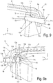
- Figures 8-10 show different exemplary embodiments of axial securing devices for pad retaining brackets 8.
- the term axial securing device is to be understood to mean that the pin element 11 is arranged parallel or essentially parallel to the brake disk rotation axis 2a.
- the end section 8b of the pad holder 8 is essentially like the variant according to Fig. 7c formed, wherein the end portion 8b is bent under the pad bracket 8.
- the securing device 10 has the pin element 11 and a securing element 15.
- the pin element 11 is fastened with its foot section 11c in the lining back plate 5a in a guide receptacle 5'c via a securing section 16.
- the securing section 16 is a circumferential groove into which a securing bolt 16a, which is inserted in the backing plate 5a in the z direction, engages. This axially secures the pin element 11 in the lining back plate 5a.
- the securing section 16 can be in a variant as a thread, press-in notches or the like. be trained. This can also be provided in addition to the securing bolt 16a.
- the pin element 11 is in the y direction, ie in the longitudinal direction of the pad retaining bracket 8 parallel to its longitudinal axis and parallel to the brake disc rotation axis 2a (see Fig. 1 ) arranged.
- the head section 11a of the pin element 11 has a circumferential groove 11f and extends in the y direction through the receptacle 8d of the retaining bracket 8, the receptacle 8d being arranged in the intermediate section 8'b between the transition sections 8c (see Fig. 7c ).
- the head section 11a of the pin element 11 protrudes through the receptacle 8d and is provided with the securing element 15, for example a shaft securing ring, which is axially fixed in the groove 11f.
- the securing element 15 for example a shaft securing ring, which is axially fixed in the groove 11f.
- Fig. 8a shows a variant of the fastening of the foot section 11c of the pin element 11 in the covering back plate 5a.
- the guide receptacle 5'c extends through the backing plate 5a in the y direction.
- the foot section 11c of the pin element 11 is designed in the shape of a conical head and is connected to the lining back plate 5a, for example by staggering, welding or riveting or the like. firmly connected.
- the axial securing with the securing element 15 is according to Fig. 8 educated.
- FIG. 9 Another variant of the safety device 10 according to Fig. 8-8a is in 9 and 9a shown in views from different sides.
- Fig. 9 the fixing of the pin element 11 with its foot portion 11c in the guide receptacle 5'c of the covering back plate 5a is carried out by means of a securing element 12 in the form of a clamp.
- the securing element 12 is U-shaped with a body 12a and two sections 12b and 12c.
- the two sections 12b, 12c demonstrate receptacles 111 according to the securing element 12 of the second exemplary embodiment Fig. 4-4a on.
- the securing element 12 is placed over the upper edge of the lining back plate 5a around the guide receptacle 5'c, the section 12b being in engagement with a groove 11h on the foot section 11c of the pin element 11. In this way, the pin element 11 is axially fixed in the guide receptacle 5'c, since the sections 12b and 12c of the securing element 12 rest on both sides of the covering back plate 5a.
- the head section 11a of the pin element 11 extends in the positive y direction through the receptacle 8d of the intermediate section 8'b and protrudes therefrom.
- the head section 11a is larger in outside diameter than the diameter or passage cross section of the receptacle 8d. This larger outer diameter of the head portion 11a is after assembly of the pad bracket 8 by compression or the like. shaped to form an axial securing of the pad retaining bracket 8 in the y direction.
- an axial lock as in Fig. 8-8a shown are used.
- the intermediate section 8'b of the pad retaining bracket 8 follows directly into the end section 8b according to the first variant Fig. 7 about.
- the securing element 12 is also U-shaped with a body 12a and two sections 12b and 12c.
- the section 12b bears against the side of the back plate 5a which faces away from the brake disc 2 and is connected to the back plate 5a in a manner not shown here, for example welded, screwed, U-shaped (as in FIG Fig. 9 ) or the like., And with a tab-shaped portion 12f similar to the variant Fig. 5-5a Mistake.
- the other section 12c is arranged in the y-direction in front of the section 12b, ie further away from the side of the back plate 5a on which the section 12b bears.
- the two sections 12b, 12c demonstrate receptacles 111 according to the securing element 12 of the second exemplary embodiment Fig. 4-4a on.
- the receptacle 111 of the section 12b is a kind of elongated hole, and the receptacle 111 of the section 12c has a U-shape.
- the pin element 11 is here divided into the following sections: head section 11a with a holding section 115, body section 116, fixing section 117, groove 11h and foot section 11c.
- the holding section 115 is provided with an oval cross-section, e.g. by compression, the greatest extent of which extends in the x direction.
- the body portion 116 has a circular cross section.
- the fixing section 117 has an oval cross-section since manufacture, which, however, is rotated by approximately 90 ° to the oval cross-section of the holding section 115 about the longitudinal axis of the pin element 11, which runs in the y direction, so that the greatest extent of the oval cross section of the fixing section 117 extends in the z direction.
- the groove 11h has a smaller diameter than an outer diameter of the foot portion 11c.
- the receptacle 8d of the pad retaining bracket 8 is an elongated hole here, which extends in the z direction.
- the pin element 11 is advanced with the foot section 11c in the negative y direction through the U-shaped receptacles 111 of the securing element 12 into the guide receptacle 5'c (see Fig. 9 ), wherein the inner edges of the receptacle 111 of the sections 12b and 12f of the securing element 12 come into engagement with the groove 11h and the tab-shaped section 12f is connected to the body 12a in the connection 14, for example by welding.
- the pin element 11 is fixed axially relative to the lining back plate 5a. A displacement in the negative y direction into the pad back plate 5a is prevented by the stop of the securing section 117 on the securing element 12, which in turn rests on the pad back plate 5a.
- the engagement of the sections 12b and 12f of the securing element 12 in the groove 11h of the pin element 11 prevents displacement of the pin element 12, since the groove 11h has a smaller inner diameter than the foot section 11c, and because the securing element 12 on the lining back plate 5a is fixed.
- the fixing section 117 When the pin element 11 is inserted, the fixing section 117 is rotated with its oval cross section about the longitudinal axis of the pin element 11 such that the fixing section 117 can be inserted into the receptacle 111 of the section 12c of the securing element 12 and the fixing section 117 is arranged in this receptacle 111, as in Fig. 9a is clearly recognizable.
- the receptacle 111 of the section 12c of the securing element 12 forms together with the oval cross section of the fixing section 117 of the pin element 11 prevents the pin element 11 from rotating about its longitudinal axis, ie here around the y direction.
- the head section 11a of the pin element 11 protrudes from it in the positive y direction through the receptacle 8d of the end section 8b of the pad retaining bracket 8. Then the oval cross section of the holding section 115 is formed in such a way that the greatest extent of the oval cross section extends in the x direction and thus forms an axial securing of the pad retaining bracket in the y direction.
- FIG. 10 Another embodiment shows Fig. 10 ,
- the pin element 11 is fastened with its foot section 11c in the covering back plate 5a in the guide receptacle 5'c.
- a recess 50 is formed around the guide receptacle 5'c, which serves to clamp a clamping element 17.
- the clamping element 17 fixes the pin element 11 axially with respect to the lining back plate 5a and at the same time forms an anti-rotation device for the pin element 11 around the y-direction.
- the body 11b adjoins in the y direction, which then merges by approximately 90 ° in a connecting section 11'a into the head section 11a, which extends upward in the z direction.
- the upper end of the head section 11a is in engagement with a recess 85, which is formed here centrally in the edge of the slightly downwardly bent end section 8b of the pad retaining bracket 8. An axial lock is thus formed.
- the pad retaining bracket 8 is also fixed against transverse movements.
- FIG. 11-15 Various exemplary embodiments of vertical securing of pad retaining brackets 8 are shown.
- the term vertical securing means that the pin element 11 is arranged in the vertical direction, that is to say in the z direction.
- Fig. 11 . 12 . 14 show variants of the first embodiment Fig. 2-3 .
- Fig. 13 and 15 represent further variants.
- the securing element 12 is fastened as a resilient clamp with two functions (securing and prestressing) with a section 12c on the upper edge of the lining back plate 5a, the other section 12b of the securing element 12 is firmly connected to the head section 11a of the pin element 11.
- the pin element 11 here has a rectangular cross section and is received in only one guide receptacle 5c of the lining back plate 5a so as to be displaceable in the z direction.
- the securing element 12 here has a slightly corrugated body 12a, to which the section 12c is attached at the bottom via an arcuate spring section 120.
- Fig. 12 shows that the securing element 12 as in the first embodiment according to Fig. 3 is in engagement with the body 11b of the pin element 11 in the opening 5b of the lining back plate 5a.
- the securing element 12 here has the body 12a, to which the spring section 120 with the section 12c is attached below. At the top, the body 12a is connected to the section 12b via another arcuate spring section 121. In contrast to the first embodiment according to Fig. 3 the end of section 12b in opening 5b is bent through 180 °. Its end can form further contact with the body 11b of the pin element 11.
- Fig. 13 shows a further variant in which only one spring element 13 is provided.
- An axial limitation of the stroke of the pin element 11 is achieved in that a securing bolt 16a engages with the area of the body 11'b, the cross section or diameter of which is reduced compared to the cross section or diameter of the foot section 11c.
- This securing bolt 16a is pressed into the lining back plate 5a in the y direction.
- a threaded bolt or grub screw is also possible.
- the stroke of the pin element 11 is determined by shoulders, which limit the reduced cross-sectional or diameter range of the body 11'b, as a stop in cooperation with the securing bolt 16a.
- the spring element 13 is clamped between the head section 11a of the pin element 11 and the upper edge of the covering back plate 5a, wherein it surrounds the body 11b of the pin element 11.
- the head section 11a of the pin element 11 is in engagement with the receptacle 8d of the pad retaining bracket 8.
- the body 11b is extended downwards by a further body 11'b, which has a smaller cross section than the body 11b.
- the end of the upper body 11b and the foot portion 11c are received in the guide receptacle 5c of the pad back plate 5a and guided on the wall of the guide receptacle 5c.
- the further body 11'b, which lies in between, is also arranged in the guide receptacle 5c without touching the wall thereof.
- outside or “outside” in connection with the lining back plate 5a are to be understood as the side thereof or the region thereof which points away from the brake disc 2.
- Fig. 14 differs from that in Fig. 12 variant shown in that the section 12c of the securing element 12 is fastened to the outside of the lining back plate 5a by means of a fastening element 18, for example a rivet or screw bolt or the like.
- the section 12b is attached to the body 12a of the securing element 12 via the spring section 121 and extends with its other end into the opening 5b for cooperation with the pin element 11.
- the pin element 11 is slidably guided with the head section 11a in the upper guide receptacle 5c and with the foot section 11c in the lower guide receptacle 5'c of the lining back plate 5a (as in the first exemplary embodiment according to FIG Fig. 3 ).
- Fig. 15 reproduces a variant of the variant Fig. 13
- the spring element 13 is arranged here in the guide receptacle 5c in a lower region and surrounds the elongated body 11'b.
- the body 11b which is located above it in the guide receptacle 5c in its upper region, is in contact with the wall of the guide receptacle 5c with two thickenings.
- the spring element 13 is supported on the lower thickening of the body 11b and on the lower end of the guide receptacle 5c on a shoulder of a cross-sectional reduction.
- the elongated body 11'b extends through this reduction in cross section through a further guide receptacle 5d downward in the negative z-direction, a thickened foot section 11c protruding on the outside and forming an axial securing of the pin element 11.
- the thickening of the foot section 11c is produced only after assembly of the pin element 11 and the spring element 13 by a material deformation, for example by staggering or the like.
- Fig. 16 shows a securing element 12 in the form of a spring clip with a body 12a, to which the spring section 120 with the section 12c is attached below is.
- the section 12c extends to the edge of the covering back plate 5a and is firmly attached there by means of a fastening element 18, for example a rivet or a screw.
- the spring section 121 is formed on the upper side of the body 12a of the securing element 12, which extends first in the negative y direction and then upwards in the z direction and is in contact with a wall of an opening 8e of the end section 8b of the pad retaining bracket 8.
- the spring section 121 is followed by the section 12b, which has an end section 122, which again points in the positive y direction.
- An inclined section is thus formed, which facilitates the spring arm formed from the curved section 122 and section 12b snapping into the opening 8e.
- the end section 122 facilitates pressing down the resilient securing element 12 in the negative z direction when the pad retaining bracket 8 is removed.
- Two or more securing elements 12 can also be provided next to one another.
- Fig. 16a shows a variant of the securing element 12 Fig. 16 .
- An arcuate spring section 120 is initially formed on the body 12a at the bottom, which is bent in such a way that the adjoining section 12c runs essentially parallel to the brake disc rotation axis 2a in the negative y direction and in front of the outer sides of the lining back plate 5a by 90 ° upwards z direction is bent.
- This piece of section 12c lying upward on the outside of the lining back plate 5a is fixedly connected to the lining back plate 5a with a fastening element 18, eg rivet.
- the body 12a of the securing element 12 extends obliquely by approximately 45 ° to the brake disc 2 and upwards, at the end of which it merges in the spring section 121 in the z direction into the section 12b, which with a straight piece as in FIG Fig. 16 is in contact with the wall of the opening 8e of the end section 8b of the pad holder 8.
- the end section 122 is provided, which is bent in the positive y direction. This end section 122 also facilitates pressing down the resilient securing element 12 in the negative z direction when the pad retaining bracket 8 is removed.
- Fig. 17 is the pad retaining bracket 8 after execution Fig. 7d formed, on the sides of the body of the pad retaining bracket 8 shortly before the transition section 8c, rectangular recesses 86 are formed on both sides, in each of which a bent clamp section 123 of the securing element 12 engages.
- the body 12a of the securing element 12 here has an elongated rectangular shape and is arranged above the edge of the pad backing plate 5a in the x-direction below the pad retaining bracket 8.
- One of the bent clamp sections 123 is formed on each of the lateral ends of the body 12a.
- the sections 12b and 12c are each bent in a trapezoidal shape by 90 ° downward in the negative z-direction, the backing plate 5a being arranged between these sections 12b and 12c.
- a narrow, elongated section 12d is formed, which is bent in the negative y direction by 90 ° to the brake disc 2 and extends through the opening 5b of the pad back plate 5a to the other trapezoidal section 12c and with it in a similar manner in connection 14 as in Fig. 4a (or Fig. 18-18a ) is firmly connected after assembly.
- the bent spring arms in the form of the end sections 123 are opened (for example with a spreading tool, e.g. spreading pliers) so that the pad retainer 8 can be inserted / removed in the brake caliper 3.
- a corresponding interference contour can be provided on the brake caliper 3 or on the pad retaining bracket 8.
- a securing element 12 is arranged with the body 12a in an envelope shape around the edge of the topping plate 5a, with a portion 12b extending through the opening 5b, the end portion of which protrudes outward through the opening 5b and with the outer portion of the body 12a is firmly connected in a connection 14, for example welded or the like.
- a tab portion 124 is formed, which has a tab 125 bent at 90 ° at its free end.
- This tab 125 is in the variant in Fig. 18a still provided with a projection 126 for disassembly / assembly.
- the tab section 124 extends in a yz plane and extends in the positive y direction, wherein it rests on a side 8f or a section of the end section 8b of the pad retaining bracket 8.
- the tab 125 lies in an xz plane and surrounds it a corner of a section or a recess of the end section 8b.
- Tab portions 124 may be provided on both sides 8f of the end portion 8b or in the opening 8e thereof.
- the tab sections 124 are pressed together, for example with a tool (pliers).
- a gap between these two (oppositely arranged) tab sections 124 which can also be referred to as spring arms, can be designed in such a way that plastic deformation is avoided since the two tab sections 124 then block each other or form a stop.
- the two tab sections 124 are spread over slopes 125a or roundings and the support of the intermediate section 8c of the pad retaining bracket 8.
- Fig. 19 delivers another variant Fig. 18-18a Instead of a tab section 124 ( Fig. 18-18a ) a hook section 127 with a hook 128 is provided.
- the body 12a of the securing element 12 is arranged in a U-shape with the sections 12b and 12c over the edge of the covering back plate 5a and is fixedly connected to the latter by means of a fastening element 18 (rivet, screw, or the like).
- the section 12c merges at its lower end via a 90 ° bend into the hook section 127, which extends in the positive y direction.
- the hook 128 is in engagement with the end section 8b of the pad retaining bracket 8.
- Two or more hook sections 127 with hooks 128 can be provided either on a securing element 12 or on several.
- FIG. 20 shows the bearing section 9 on the application side of the brake caliper 3.
- a holding section 19 is in engagement with the application-side end section 8a of the pad retaining bracket 8.
- the holding section 19 is hook-shaped and engages in a recess 8'a of the pad retaining bracket 8.
- the hook section 19 has a slope 9d, which is in contact with a slope 87 in the recess 8'a of the tensioning-side end section 8a of the pad retaining bracket 8. This makes assembly easier, a latching function being formed and the pad retaining bracket 8 being fixed in the y direction.
- the rear end section 8b has a curvature 20 which curves upwards in the positive z direction and is in contact with the upper side of the receptacle 9b in the holding section 9a.
- Fig. 22 shows the pairing of bevels 87 and 9d on the holding section 9a similar to the bearing section 9 according to FIG Fig. 20 .
- the receptacle 9b of the holding section 9a has a further recess 9c as a depression in the negative z direction.
- the top of the receptacle 9b is also provided with a recess 9'c, which has the bevel 9d on the inside in the x direction.
- the end section 8b of the pad retaining bracket 8 is provided on its outside, which extends in the x direction, with the bevel 87, which is in contact with the bevel 9d.
- FIG. 23 Another, additional securing of the pad retaining bracket 8 in the y direction is in Fig. 23 shown.
- a stop 88 protruding in the negative z direction is formed and / or formed, which interacts with an edge section 70 of the pad retaining spring 7 of the back pad covering plate 5a. If the pad holder 8 is produced as a stamped and bent part, the stop 88 can be produced in one operation, for example by pressing in the stamped and bent process.
- the assembly of the pad retaining bracket 8 together with the securing device 10 will now be briefly described.
- the securing device 10 ensures, on the one hand, an automatic engagement of the pin element 11 and / or the spring-like securing element 12 in the receptacles provided for this purpose (either in the pad backing plate 5a or in the pad retaining bracket 8) and, on the other hand, simple detachability for service work.
- the spring arms of the spring-like securing elements 12 are displaced elastically so that the pad retainer 8 can be used in the brake caliper 3.
- the spring arms remain biased by the pad retaining bracket 8. After this is pushed into its final position the spring arms spring back into their original position.
- the spring arms are now unloaded and are not loaded during operation. This prevents the spring arms from being set (e.g. due to the effects of temperature).
- the comprehensive sections (e.g. 123 in Fig. 17 , 125) of the spring arms prevent displacement of the pad holding bracket 8 in the direction of the brake disk rotation axis 2a, ie in the y direction. The pad retaining bracket is thus secured.
- the spring arms are shifted on the pad back plate 5 a, for example with a tool, until the encompassing tab sections 124 release the pad retaining bracket 8.
- the spring arms must be held in position until the pad retaining bracket 8 is sufficiently moved during disassembly to keep it open.
- the brake pad set 100 with the securing device 10 can be used in all disc brakes 1 with a sliding caliper, in particular for commercial vehicles.
Landscapes
- Engineering & Computer Science (AREA)
- General Engineering & Computer Science (AREA)
- Mechanical Engineering (AREA)
- Braking Arrangements (AREA)
Abstract
Eine Scheibenbremse (1) für ein Fahrzeug, insbesondere für ein Nutzfahrzeug, umfasst eine Bremsscheibe (2) mit einer Bremsscheibendrehachse (2a), einen Bremssattel (3), insbesondere ein Schiebesattel, mit einem Zuspannabschnitt (3a) und einem Rückenabschnitt (3b), mindestens zwei Bremsbeläge (4, 5) mit jeweils einer mit einer Belaghaltefeder (6, 7) versehenen Belagrückenplatte (4a, 5a), die jeweils unter Vorspannung von einem am Bremssattel (3) lösbar befestigten Belaghaltebügel (8) abgestützt sind und von denen ein zuspannseitiger Bremsbelag (4) dem Zuspannabschnitt (3a) zugeordnet ist, und ein rückenseitiger Bremsbelag (5) dem Rückenabschnitt (3b) zugeordnet ist, sowie eine Sicherheitsvorrichtung (10) zur Sicherung der Position des Belaghaltebügels (8). wobei eine Sicherungselement (12) einen Körper (12a) mit einer länglichen Rechteckform aufweist, an dessen seitlichen schmalen Enden jeweils ein nach oben umgebogener, federnder Klammerabschnitt (123) für eine formschlüssigen Verbindung mit dem Belaghaltebügel (8) angeformt ist, und an dessen langen Seiten beiderseits jeweils ein trapezförmiger Abschnitt (12b, 12c) rechtwinklig nach unten weisend angebracht ist,wobei die unteren Enden der trapezförmigen Abschnitte (12b, 12c) durch einen Abschnitt (12d) verbunden sind, wobei ein Abschnitt der rückenseitigen Belagrückenplatte (5a) zwischen den trapezförmigen Abschnitten (12b, 12c) angeordnet ist.A disc brake (1) for a vehicle, in particular for a commercial vehicle, comprises a brake disc (2) with a brake disc rotation axis (2a), a brake caliper (3), in particular a sliding caliper, with an application section (3a) and a back section (3b), at least two brake pads (4, 5), each with a pad backing plate (4, 5a) provided with a pad retaining spring (6, 7), each of which is pretensioned and supported by a pad retaining bracket (8) releasably attached to the brake caliper (3) and one of which brake application side (4) is assigned to the application section (3a), and a brake pad (5) on the rear side is assigned to the back section (3b), and a safety device (10) for securing the position of the pad retainer (8). wherein a securing element (12) has a body (12a) with an elongated rectangular shape, on the lateral narrow ends of which an upwardly bent, resilient clamp section (123) is integrally formed for a positive connection with the pad retaining bracket (8), and on the long one On both sides, a trapezoidal section (12b, 12c) is attached at right angles pointing downwards, the lower ends of the trapezoidal sections (12b, 12c) being connected by a section (12d), a section of the backing covering plate (5a) between the trapezoidal sections (12b, 12c) is arranged.
Description
Die vorliegende Erfindung betrifft eine Scheibenbremse mit Belaghaltebügel und Sicherungsvorrichtung nach dem Oberbegriff des Anspruchs 1. Die Erfindung bezieht sich auch auf einen Bremsbelagsatz für eine solche Scheibenbremse.The present invention relates to a disc brake with pad retainer and safety device according to the preamble of
Bremsbeläge von Scheibenbremsen, insbesondere pneumatische Scheibenbremsen, in Fahrzeugen, z.B. Nutzfahrzeugen, werden in so genannten Belagschächten durch einen Belaghaltebügel gehalten. Damit der Belaghaltebügel nicht durch Querkräfte im Fahrzeug aus seiner Position verschoben werden kann, sind zusätzliche Bauelemente notwendig, die nicht nur ein Verschieben des Haltebügels, insbesondere bei Betrieb, verhindern, sondern auch eine Montage und Demontage ermöglichen.Brake pads of disc brakes, especially pneumatic disc brakes, in vehicles, e.g. Commercial vehicles are held in so-called covering shafts by a covering bracket. So that the pad retaining bracket cannot be shifted from its position by transverse forces in the vehicle, additional components are required which not only prevent the retaining bracket from shifting, in particular during operation, but also enable assembly and disassembly.
Diese zusätzlichen Bauelemente umfassen z.B. Kombinationen aus Bolzen und Sicherungssplinten, Federelementen und Schrauben. Nach Einsetzen der Bremsbeläge und Montage des Belaghaltebügels kann danach die Anbringung der Bauelemente zur Sicherung vom Mechaniker vergessen werden. Eine Sicherung der Beläge ist damit nur für eine unbestimmte Zeit gegeben, der Fehler ist zwangsläufig nicht auffällig. Der Belaghaltebügel kann im schlimmsten Fall u.U. im Betrieb verrutschen und eine Sicherung der Bremsbeläge beeinträchtigen.These additional components include e.g. Combinations of bolts and safety pins, spring elements and screws. After inserting the brake pads and installing the pad retainer, the mechanic can forget to attach the components to secure them. The coverings are only secured for an indefinite period, the error is not necessarily noticeable. In the worst case, the pad retaining bracket may slip during operation and impair the securing of the brake pads.
Es sind zahlreiche Vorschläge für derartige Sicherungsbauelemente und Sicherungsvorrichtungen gemacht worden. Ein Beispiel zur Illustration zeigt das Dokument
Es besteht ein ständiger Bedarf nach erhöhter Funktionssicherheit im Betrieb, geringen Herstellkosten, sowie kürzeren Servicezeiten.There is a constant need for increased operational reliability, low manufacturing costs and shorter service times.
Der Erfindung liegt die Aufgabe zu Grunde, eine verbesserte Scheibenbremse zu schaffen.The invention is based on the object of providing an improved disc brake.
Eine weitere Aufgabe besteht darin, einen verbesserten Bremsbelagsatz für eine Scheibenbremse bereitzustellen.Another object is to provide an improved brake pad set for a disc brake.
Die Erfindung löst diese Aufgabe durch den Gegenstand des Anspruchs 1. Diese Aufgabe wird auch durch die Gegenstände der Ansprüche 6, 8, 9, 11 und 12 gelöst.The invention solves this problem by the subject matter of
Die weitere Aufgabe wird durch den Gegenstand des Anspruchs 15 gelöst.The further object is solved by the subject matter of
Eine Sicherheitsvorrichtung ist mit einem Stiftelement versehen, welches verschiebbar ist und in eine Eingriffsposition vorgespannt ist. Dadurch ergibt sich eine lösbare Verbindung zu dem Belaghaltebügel, der auf diese Weise ohne Werkzeug ein- und ausbaubar ist. Die Sicherheitsvorrichtung gegen Verschieben des Belaghaltebügels stützt sich an einem Bremsbelag ab, und zwar an dem rückenseitigen Bremsbelag bzw. an dessen Belagträgerplatte. Die Sicherheitsvorrichtung kann auch mit dem Belaghaltebügel oder dem Bremsbelag fest und unverlierbar verbunden sein.A safety device is provided with a pin element which is displaceable and is biased into an engagement position. This results in a detachable connection to the pad retaining bracket, which can be installed and removed in this way without tools. The safety device against displacement of the pad retaining bracket is supported on a brake pad, namely on the rear brake pad or on its pad carrier plate. The safety device can also be firmly and captively connected to the pad retaining bracket or the brake pad.
Eine Scheibenbremse für ein Fahrzeug, insbesondere für ein Nutzfahrzeug, umfasst eine Bremsscheibe mit einer Bremsscheibendrehachse, einen Bremssattel, insbesondere ein Schiebesattel, mit einem Zuspannabschnitt und einem Rückenabschnitt, mindestens zwei Bremsbeläge mit jeweils einer mit einer Belaghaltefeder versehenen Belagrückenplatte, die jeweils unter Vorspannung von einem am Bremssattel lösbar befestigten Belaghaltebügel abgestützt sind und von denen ein zuspannseitiger Bremsbelag dem Zuspannabschnitt zugeordnet ist, und ein rückenseitiger Bremsbelag dem Rückenabschnitt zugeordnet ist, sowie eine Sicherheitsvorrichtung zur Sicherung der Position des Belaghaltebügels. Die Sicherheitsvorrichtung weist mindestens ein verschiebbar geführtes Stiftelement auf, welches aus einer Ruheposition in eine Eingriffsposition und zurück verschiebbar ist, wobei das mindestens eine Stiftelement in der Eingriffsposition eine lösbare Verbindung zwischen dem Belaghaltebügel und der Belagrückenplatte des rückenseitigen Bremsbelags bildet.A disc brake for a vehicle, in particular for a commercial vehicle, comprises a brake disc with a brake disc rotation axis, a brake caliper, in particular a sliding caliper, with an application section and a back section, at least two brake pads, each with a pad backing plate provided with a pad retaining spring, each preloaded by one pad retainers releasably attached to the brake caliper are supported and of which an application-side brake pad is assigned to the application section, and a back-side brake pad is assigned to the back section, and a safety device for securing the position of the pad retainer. The safety device has at least one displaceably guided pin element which is displaceable from a rest position into an engagement position and back, the at least one pin element in the engagement position forming a detachable connection between the pad retaining bracket and the pad back plate of the rear brake pad.
Das in der rückenseitigen Belagträgerplatte integrierte Stiftelement rastet bei Montage des Belaghaltebügels automatisch in einer zugehörigen Aufnahme ein und ist für Servicearbeiten wieder lösbar, jedoch nicht entfernbar.The pin element integrated in the backing pad plate automatically engages in an associated receptacle when the pad holding bracket is installed and can be removed again for service work, but cannot be removed.
Da der rückenseitige Bremsbelag bei Scheibenbremsen mit Schiebesattel keine Relativbewegungen zum Bremssattel aufweist, ist dies von Vorteil.This is an advantage because the rear brake lining of disc brakes with a sliding caliper has no relative movements to the brake caliper.
Die Vorspannung des Stiftelementes kann dadurch erfolgen, dass die Sicherheitsvorrichtung mindestens ein Federelement zur Vorspannung des mindestens einen verschiebbar geführten Stiftelementes in die Eingriffsposition umfasst, wobei das mindestens eine Stiftelement bei Montage/Demontage gegen die Vorspannkraft des Federelementes in die Ruheposition verschiebbar ist. Damit ist es vorteilhaft möglich, dass eine Montage einfach erfolgen kann, wobei außerdem durch ein einfaches Verschieben des Stiftelementes gegen die Vorspannkraft des Federelementes, z.B. mittels eines geeigneten Werkzeugs, eine leichte Demontage gewährleistet werden kann.The pretensioning of the pin element can take place in that the safety device comprises at least one spring element for pretensioning the at least one displaceably guided pin element into the engagement position, the at least one pin element during assembly / disassembly against the pretensioning force of the spring element can be moved into the rest position. It is thus advantageously possible that assembly can be carried out easily, and easy disassembly can also be ensured by simply moving the pin element against the pretensioning force of the spring element, for example by means of a suitable tool.
Für Herstellung einer Unverlierbarkeit des Stiftelementes weist die Sicherheitsvorrichtung vorteilhaft mindestens ein Sicherungselement auf, welches eine Begrenzung eines Hubs des mindestens einen Stiftelementes bildet.To make the pin element captive, the safety device advantageously has at least one securing element, which forms a limitation of a stroke of the at least one pin element.
Wenn das mindestens eine Sicherungselement die Funktion des mindestens einen Federelementes zur Vorspannung des mindestens einen verschiebbar geführten Stiftelementes aufweist, ergibt dies eine Reduktion von Bauteilen.If the at least one securing element has the function of the at least one spring element for prestressing the at least one displaceably guided pin element, this results in a reduction in components.
Hierzu kann das mindestens eine Sicherungselement als eine elastische Klammer, z.B. aus Blech, ausgebildet sein, welche mit einem Abschnitt mit dem mindestens einen Stiftelement verbunden ist und mit einem anderen Abschnitt an einem ortsfesten Abschnitt, in oder an welchem das mindestens eine verschiebbare Stiftelement verschiebbar geführt ist, verbunden ist oder in Kontakt steht.For this purpose, the at least one securing element can be used as an elastic clip, e.g. be made of sheet metal, which is connected to one section with the at least one pin element and with another section at a fixed section, in or on which the at least one displaceable pin element is slidably guided, connected or in contact.
Es ist vorgesehen, dass das mindestens eine Sicherungselement mindestens einen Abschnitt, welcher mit dem mindestens einen Stiftelement verbunden ist, und mindestens einen weiteren Abschnitt, welcher mit einem ortsfesten Abschnitt, in oder an dem das mindestens eine verschiebbare Stiftelement verschiebbar geführt ist, verbunden ist oder in Kontakt steht, aufweist. So ist eine einfache Montage des Sicherungselementes möglich.It is provided that the at least one securing element is connected to at least one section which is connected to the at least one pin element and at least one further section which is connected to a fixed section in or on which the at least one displaceable pin element is displaceably guided is in contact. A simple assembly of the securing element is thus possible.
In einer Ausführung ist das mindestens eine verschiebbare Stiftelement in mindestens einer Führungsaufnahme der Belagrückenplatte des rückenseitigen Bremsbelags verschiebbar geführt, und der mindestens eine Abschnitt des mindestens einen Sicherungselementes, welcher mit dem mindestens einen Stiftelement verbunden ist, ist mit dem mindestens einen weiteren Abschnitt des mindestens einen Sicherungselementes in einer Verbindung unlösbar verbunden, wobei die so verbundenen Abschnitte einen Abschnitt der Belagrückenplatte umgreifen und sich durch eine Öffnung der Belagrückenplatte hindurch erstrecken. Das auf diese Weise einfach montierte Sicherungselement wird nach seiner Montage dann z.B. durch Verschweißen, seiner Abschnitte unlösbar an der Belagrückenplatte angebracht, wobei es aber die Hubbewegung des Stiftelementes zulässt.In one embodiment, the at least one displaceable pin element is slidably guided in at least one guide receptacle of the lining back plate of the rear brake lining, and the at least one section of the at least one securing element, which is connected to the at least one pin element, is connected to the at least one further section of the at least one Securing element connected in a non-detachable connection, the sections connected in this way encompassing a section of the covering back plate and extending through an opening in the covering back plate. The securing element, which is simply mounted in this way, is then inseparably attached to the covering back plate after its assembly, for example by welding, but it allows the lifting movement of the pin element.
In einer alternativen Ausführung ist das mindestens eine verschiebbare Stiftelement in mindestens einer Führungsaufnahme der rückenseitigen Belagrückenplatte des rückenseitigen Bremsbelags verschiebbar geführt, und der mindestens eine Abschnitt des mindestens einen Sicherungselementes, welcher mit dem mindestens einen Stiftelement verbunden ist, ist mit dem mindestens einen weiteren Abschnitt des mindestens einen Sicherungselementes durch einen weiteren Abschnitt des mindestens einen Sicherungselementes in einer Verbindung unlösbar verbunden, wobei das mindestens eine Sicherungselement in einer Öffnung der rückenseitigen Belagrückenplatte angeordnet ist.In an alternative embodiment, the at least one displaceable pin element is displaceably guided in at least one guide receptacle of the rear pad back plate of the rear brake pad, and the at least one section of the at least one securing element, which is connected to the at least one pin element, is connected to the at least one further section of the at least one securing element is non-releasably connected in a connection by a further section of the at least one securing element, the at least one securing element being arranged in an opening in the rear covering plate.
In einer anderen alternativen Ausführung ist das mindestens eine verschiebbare Stiftelement in mindestens einer Führungsaufnahme der rückenseitigen Belagrückenplatte des rückenseitigen Bremsbelags verschiebbar geführt, und der mindestens eine Abschnitt des mindestens einen Sicherungselementes ist mit dem mindestens einen Stiftelement verbunden, und der mindestens eine weitere Abschnitt ist an der rückenseitigen Belagrückenplatte des rückenseitigen Bremsbelags fest angebracht. Das Sicherungselement kann z.B. auch ein kostengünstiger Wellensicherungsring sein, der mit dem mindestens einen verschiebbar geführten Stiftelement verbunden ist.In another alternative embodiment, the at least one displaceable pin element is displaceably guided in at least one guide receptacle of the rear pad back plate of the rear brake pad, and the at least one section of the at least one securing element is connected to the at least one pin element, and the at least one further section is on the rear pad back plate of the rear brake pad firmly attached. The securing element can e.g. also be an inexpensive shaft locking ring which is connected to the at least one displaceably guided pin element.
In einer anderen Ausführung kann das mindestens eine Sicherungselement durch eine Materialumformung, z.B. Stauchen, Vertaumeln, Nieten oder dergleichen, des mindestens einen Stiftelementes geformt sein. Damit lässt sich ein raumsparender Aufbau erreichen.In another embodiment, the at least one securing element can be formed by material deformation, e.g. Upset, staggering, riveting or the like of the at least one pin element. This enables a space-saving construction to be achieved.
Das mindestens eine verschiebbar geführte Stiftelement kann auch in einer Aufnahme des Belagbügels verschiebbar geführt und am Belaghaltebügel gehalten sein, wobei ein Kopf des mindestens einen verschiebbar geführten Stiftelementes als das mindestens eine Sicherungselement geformt ist, und wobei ein Fußabschnitt des mindestens einen verschiebbar geführten Stiftelementes mit einer Führungsaufnahme der rückenseitigen Belagrückenplatte des rückenseitigen Bremsbelags in der Eingriffsposition in Eingriff steht. Auch hier wird der rückenseitige Bremsbelag verwendet.The at least one displaceably guided pin element can also be displaceably guided in a receptacle of the covering bracket and held on the pad retaining bracket, wherein a head of the at least one displaceably guided pin element is shaped as the at least one securing element, and a foot section of the at least one displaceably guided pin element with a Guide receptacle of the back pad back plate of the back brake pad is engaged in the engagement position. The rear brake pad is also used here.
In einer erfindungsgemäßen Ausführung umfasst eine Scheibenbremse für ein Fahrzeug, insbesondere für ein Nutzfahrzeug, eine Bremsscheibe mit einer Bremsscheibendrehachse, einen Bremssattel, insbesondere ein Schiebesattel, mit einem Zuspannabschnitt und einem Rückenabschnitt, mindestens zwei Bremsbeläge mit jeweils einer mit einer Belaghaltefeder versehenen Belagrückenplatte, die jeweils unter Vorspannung von einem am Bremssattel lösbar befestigten Belaghaltebügel abgestützt sind und von denen ein zuspannseitiger Bremsbelag dem Zuspannabschnitt zugeordnet ist, und ein rückenseitiger Bremsbelag dem Rückenabschnitt zugeordnet ist, sowie eine Sicherheitsvorrichtung zur Sicherung der Position des Belaghaltebügels. Hierbei weist die Sicherheitsvorrichtung mindestens ein mit der rückenseitigen Belagträgerplatte des rückenseitigen Bremsbelags verbundenes Stiftelement auf, welches sich parallel zu der Bremsscheibendrehachse und mit einer Aufnahme eines Endabschnitts des Belaghaltebügels in Eingriff steht.In an embodiment according to the invention, a disc brake for a vehicle, in particular for a commercial vehicle, comprises a brake disc with a brake disc rotation axis, a brake caliper, in particular a sliding caliper, with an application section and a back section, at least two brake pads each a pad backing plate provided with a pad retaining spring, each of which is pretensioned by a pad retainer which is detachably attached to the brake caliper and of which a brake pad on the application side is assigned to the application section, and a brake pad on the rear side is assigned to the back section, and a safety device for securing the position of the pad retainer. Here, the safety device has at least one pin element which is connected to the back-side pad carrier plate of the back-side brake pad and which engages parallel to the brake disk axis of rotation and with a receptacle of an end section of the pad holding bracket.
Der Eingriff des Stiftelementes mit dem Endabschnitt des Belaghaltebügels kann wieder lösbar sein. Es ist alternativ aber möglich, dass der Eingriff unlösbar ist.The engagement of the pin element with the end section of the pad retaining bracket can be released again. Alternatively, however, it is possible that the intervention cannot be undone.
Ein unlösbarer Eingriff kann z.B. dadurch realisiert werden, dass ein Kopfabschnitt des Stiftelementes, der durch eine Aufnahme/Öffnung des Belaghaltebügels hervorsteht, nach Montage des Belaghaltebügels mechanisch verformt oder/und mit einem axialen Sicherungsmittel unlösbar versehen wird (z.B. angeschweißter Sicherungsring)An undetachable intervention can e.g. can be realized in that a head section of the pin element, which protrudes through a receptacle / opening of the pad retaining bracket, is mechanically deformed after assembly of the pad retaining bracket and / or is permanently provided with an axial securing means (e.g. welded-on securing ring)
Es ist dabei vorgesehen, dass die Sicherheitsvorrichtung mindestens ein Sicherungselement aufweist, welches an einem Kopfabschnitt des mindestens einen Sicherungselementes, der sich durch die Aufnahme des Endabschnitts des Belaghaltebügels hindurch erstreckt und daraus hervorsteht, wieder lösbar angebracht ist. Das Sicherungselement kann z.B. ein Wellensicherungsring oder auch eine Klemmhülse sein. Damit ist eine leichte Montage/Demontage möglich.It is provided that the safety device has at least one securing element which is detachably attached to a head section of the at least one securing element which extends through the receptacle of the end section of the pad retaining bracket and protrudes therefrom. The securing element can e.g. a shaft lock ring or a ferrule. This enables easy assembly / disassembly.
Das mindestens eine Stiftelement ist dabei in einer Führungsaufnahme der rückenseitigen Belagträgerplatte des rückenseitigen Bremsbelags aufgenommen und axial gegenüber der rückenseitigen Belagträgerplatte festgelegt. Eine solche Festlegung kann z.B. durch ein klammerartiges Sicherungselement gebildet sein. Ein solches klammerartiges Sicherungselement kann auch für eine Verdrehsicherung des Stiftelementes verwendet werden, wenn es z.B. ein Langloch aufweist, das mit einem Fixierabschnitt des Stiftelementes zusammenwirkt, wobei der Fixierabschnitt einen ovalen Querschnitt besitzt.
Es ist aber auch möglich, dass die axiale Festlegung des mindestens einen Stiftelementes in der Führungsaufnahme der rückenseitigen Belagträgerplatte durch Materialumformung, z.B. Stauchen, Vertaumeln, Nieten oder dergleichen, des mindestens einen Stiftelementes gebildet ist.The at least one pin element is received in a guide receptacle of the back-side pad carrier plate of the back-side brake pad and is axially fixed with respect to the back-side pad carrier plate. Such a definition can be formed, for example, by a clip-like securing element. Such a clamp-like securing element can also be used for securing the pin element against rotation, for example if it has an elongated hole which interacts with a fixing section of the pin element, the fixing section having an oval cross section.
However, it is also possible for the at least one pin element to be fixed axially in the guide receptacle of the backing plate carrier plate by material shaping, for example upsetting, staggering, riveting or the like, of the at least one pin element.
In einer weiteren alternativen Ausführung umfasst eine Scheibenbremse für ein Fahrzeug, insbesondere für ein Nutzfahrzeug, eine Bremsscheibe mit einer Bremsscheibendrehachse, einen Bremssattel, insbesondere ein Schiebesattel, mit einem Zuspannabschnitt und einem Rückenabschnitt, mindestens zwei Bremsbeläge mit jeweils einer mit einer Belaghaltefeder versehenen Belagrückenplatte, die jeweils unter Vorspannung von einem am Bremssattel lösbar befestigten Belaghaltebügel abgestützt sind und von denen ein zuspannseitiger Bremsbelag dem Zuspannabschnitt zugeordnet ist, und ein rückenseitiger Bremsbelag dem Rückenabschnitt zugeordnet ist, sowie eine Sicherheitsvorrichtung zur Sicherung der Position des Belaghaltebügels. Die Sicherheitsvorrichtung weist mindestens ein mit der rückenseitigen Belagträgerplatte des rückenseitigen Bremsbelags verbundenes Stiftelement mit einem Körper aufweist, der sich parallel zu der Bremsscheibendrehachse erstreckt und mit einem dazu rechtwinkligen Kopfabschnitt verbunden ist, der mit einer Ausnehmung eines Endabschnitts des Belaghaltebügels wieder lösbar in Eingriff steht. Damit kann ein einfach herzustellender Belaghaltebügel Verwendung finden.In a further alternative embodiment, a disc brake for a vehicle, in particular for a commercial vehicle, comprises a brake disc with a brake disc axis of rotation, a brake caliper, in particular a sliding caliper, with an application section and a back section, at least two brake pads, each with a pad backing plate provided with a pad retaining spring are each pretensioned by a brake bracket that is releasably attached to the brake caliper and of which a brake pad on the application side is assigned to the application section, and a brake pad on the rear side is assigned to the back section, and a safety device for securing the position of the brake pad holder. The safety device has at least one pin element which is connected to the back-side pad carrier plate of the back-side brake pad and has a body which extends parallel to the brake disc rotation axis and is connected to a head section which is at right angles thereto and which is releasably engaged again with a recess in an end section of the pad holding bracket. This makes it easy to use a pad retaining bracket.
Das mindestens eine Stiftelement ist dabei in einer Führungsaufnahme der rückenseitigen Belagträgerplatte des rückenseitigen Bremsbelags aufgenommen und axial gegenüber der rückenseitigen Belagträgerplatte festgelegt. Für diese Festlegung sind unterschiedliche Elemente möglich, wie z.B. ein Klemmring, eine Klemmhülse u.dgl.The at least one pin element is received in a guide receptacle of the back-side pad carrier plate of the back-side brake pad and is axially fixed with respect to the back-side pad carrier plate. Different elements are possible for this definition, e.g. a clamping ring, a clamping sleeve and the like.
Ein solches Element zur axialen Festleung kann auch als Verdrehsicherung des Stiftelementes ausgebildet sein, z.B. in ovaler Form in einer Langlochaufnahme, die rechtwinklig zur Längsachse des Stiftelementes in der Belagrückenplatte verläuft.Such an element for the axial fixation can also be designed to prevent rotation of the pin element, e.g. in an oval shape in an elongated hole receptacle that runs at right angles to the longitudinal axis of the pin element in the backing plate.
Eine noch weitere Alternative schafft eine Scheibenbremse für ein Fahrzeug, insbesondere für ein Nutzfahrzeug, eine Bremsscheibe mit einer Bremsscheibendrehachse, einen Bremssattel, insbesondere ein Schiebesattel, mit einem Zuspannabschnitt und einem Rückenabschnitt, mindestens zwei Bremsbeläge mit jeweils einer mit einer Belaghaltefeder versehenen Belagrückenplatte, die jeweils unter Vorspannung von einem am Bremssattel lösbar befestigten Belaghaltebügel abgestützt sind und von denen ein zuspannseitiger Bremsbelag dem Zuspannabschnitt zugeordnet ist, und ein rückenseitiger Bremsbelag dem Rückenabschnitt zugeordnet ist, sowie eine Sicherheitsvorrichtung zur Sicherung der Position des Belaghaltebügels, wobei die Sicherheitsvorrichtung mindestens einen Federabschnitt aufweist, der mit einem Endabschnitt des Belaghaltebügels in Eingriff steht. In diesem Fall weist die Sicherheitsvorrichtung mindestens ein mit der rückenseitigen Belagträgerplatte des rückenseitigen Bremsbelags fest verbundenes Sicherungselement in Form einer Federklammer mit einem Körper mit dem mindestens einen Federabschnitt auf.A still further alternative provides a disc brake for a vehicle, in particular for a commercial vehicle, a brake disc with a brake disc rotation axis, a brake caliper, in particular a sliding caliper, with an application section and a back section, at least two brake pads, each with a pad backing plate provided with a pad retaining spring, each of which are pretensioned and supported by a brake retaining bracket releasably attached to the brake caliper and of which a brake lining on the application side is assigned to the application section, and a brake lining on the rear side is assigned to the back section, and a safety device for securing the position of the brake rail bracket, the safety device having at least one spring section which engages with an end portion of the pad retainer. In this case, the safety device has at least one with the rear facing carrier plate of the back Brake pad firmly connected securing element in the form of a spring clip with a body with the at least one spring section.
Hierbei ist es vorgesehen, dass das mindestens eine Sicherungselement mit einem Abschnitt des Körpers auf einem oberen Rand oder/und auf einer Seite der rückenseitigen Belagträgerplatte des rückenseitigen Bremsbelags mit einem Befestigungselement, vorzugsweise Niet, fest angebracht ist und wobei sich der Abschnitt des Körpers von der rückenseitigen Belagträgerplatte weiter in Richtung der Bremsscheibendrehachse von der Bremsscheibe hinweg erstreckt. Damit ist eine unverlierbare Ausführung geschaffen, welche außerdem den Vorteil einer leichten Erreichbarkeit aufweist.It is provided that the at least one securing element with a portion of the body on an upper edge and / or on one side of the rear pad carrier plate of the rear brake pad is firmly attached with a fastening element, preferably rivet, and wherein the portion of the body is from the the rear lining carrier plate extends further in the direction of the brake disc rotation axis away from the brake disc. This creates a captive version, which also has the advantage of being easily accessible.
In einer anderen Alternative ist eine Scheibenbremse für ein Fahrzeug, insbesondere für ein Nutzfahrzeug, geschaffen. Die Scheibenbremse umfasst eine Bremsscheibe mit einer Bremsscheibendrehachse, einen Bremssattel, insbesondere ein Schiebesattel, mit einem Zuspannabschnitt und einem Rückenabschnitt, mindestens zwei Bremsbeläge mit jeweils einer mit einer Belaghaltefeder versehenen Belagrückenplatte, die jeweils unter Vorspannung von einem am Bremssattel lösbar befestigten Belaghaltebügel abgestützt sind und von denen ein zuspannseitiger Bremsbelag dem Zuspannabschnitt zugeordnet ist, und ein rückenseitiger Bremsbelag dem Rückenabschnitt zugeordnet ist, sowie eine Sicherheitsvorrichtung zur Sicherung der Position des Belaghaltebügels, wobei die Sicherheitsvorrichtung mindestens einen Federabschnitt aufweist, der mit einem Endabschnitt des Belaghaltebügels in Eingriff steht, wobei die Sicherheitsvorrichtung mindestens ein mit der rückenseitigen Belagträgerplatte des rückenseitigen Bremsbelags fest verbundenes Sicherungselement mit dem mindestens einen Federabschnitt aufweist, welches an der rückenseitigen Belagrückenplatte des rückenseitigen Bremsbelags unlösbar angebracht ist, wobei sich ein Abschnitt des Sicherungselementes durch die Öffnung der rückenseitigen Belagrückenplatte hindurch erstreckt. Hierbei ist vorgesehen, dass das mindestens eine Sicherungselement einen Körper mit einer länglichen Rechteckform aufweist, an dessen seitlichen schmalen Enden jeweils ein nach oben umgebogener, federnder Klammerabschnitt für eine formschlüssigen Verbindung mit dem Belaghaltebügel angeformt ist, und an dessen langen Seiten beiderseits jeweils ein trapezförmiger Abschnitt rechtwinklig nach unten weisend angebracht ist, wobei die unteren Enden der trapezförmigen Abschnitte durch einen Abschnitt verbunden sind, wobei ein Abschnitt der rückenseitigen Belagrückenplatte zwischen den trapezförmigen Abschnitten angeordnet ist.In another alternative, a disc brake is created for a vehicle, in particular for a commercial vehicle. The disc brake comprises a brake disc with a brake disc rotation axis, a brake caliper, in particular a sliding caliper, with an application section and a back section, at least two brake pads, each with a pad backing plate provided with a pad retainer spring, which are each pretensioned and supported by a pad retainer that is detachably attached to the brake caliper and by to which an application-side brake pad is assigned to the application section, and a back-side brake pad to the back section, and a safety device for securing the position of the pad retaining bracket, wherein the security device has at least one spring section which is in engagement with an end portion of the pad retaining bracket, the security device at least has a securing element with the at least one spring section, which is firmly connected to the back-side pad carrier plate of the back-side brake pad and which at de r the rear pad back plate of the rear brake pad is permanently attached, a section of the securing element extending through the opening of the back pad back plate. It is provided that the at least one securing element has a body with an elongated rectangular shape, on the lateral narrow ends of which an upwardly bent, resilient clamp section is formed for a positive connection to the pad retaining bracket, and on the long sides of which a trapezoidal section is formed on both sides is attached at right angles pointing downwards, the lower ends of the trapezoidal sections being connected by a section, a section of the back-side covering back plate being arranged between the trapezoidal sections.
In dieser vorteilhaft raumsparenden Ausführung ist das mindestens eine Sicherungselement an der rückenseitigen Belagrückenplatte des rückenseitigen Bremsbelags unlösbar angebracht, wobei sich ein Abschnitt des Sicherungselementes durch die Öffnung der rückenseitigen Belagrückenplatte hindurch erstreckt. Dazu weist das mindestens eine Sicherungselement einen Körper mit einer länglichen Rechteckform auf, an dessen seitlichen schmalen Enden jeweils ein nach oben umgebogener, federnder Klammerabschnitt für eine formschlüssigen Verbindung mit dem Belaghaltebügel angeformt ist, und an dessen langen Seiten beiderseits jeweils ein trapezförmiger Abschnitt rechtwinklig nach unten weisend angebracht ist, wobei die unteren Enden der trapezförmigen Abschnitte durch einen Abschnitt verbunden sind, wobei ein Abschnitt der rückenseitigen Belagrückenplatte zwischen den trapezförmigen Abschnitten angeordnet ist. Dieses Bauteil kann als Stanzbiegeteil einfach und kostengünstig hergestellt werden.In this advantageously space-saving embodiment, the at least one securing element is attached to the back-side pad back plate of the back-side brake pad, with a portion of the securing element extending through the opening of the back-side pad back plate. For this purpose, the at least one securing element has a body with an elongated rectangular shape, on the lateral narrow ends of which an upwardly bent, resilient clamp section is formed for a positive connection to the pad retaining bracket, and on the long sides of which in each case a trapezoidal section is at right angles downwards is arranged pointing, the lower ends of the trapezoidal sections are connected by a section, wherein a portion of the back-side facing back plate is arranged between the trapezoidal sections. This component can be produced simply and inexpensively as a stamped and bent part.
Für eine einfache Verbindung stehen die federnden Klammerabschnitte zur formschlüssigen Verbindung mit dem Belaghaltebügel jeweils mit einer von an jeder Seite des Belaghaltebügels eingeformten rechteckigen Ausnehmungen in Eingriff.For a simple connection, the resilient clamp sections are in engagement with a rectangular recesses formed on each side of the covering holding bracket for the positive connection to the covering holding bracket.
Eine noch andere Alternative schafft eine Scheibenbremse für ein Fahrzeug, insbesondere für ein Nutzfahrzeug, aufweisend eine Bremsscheibe mit einer Bremsscheibendrehachse, einen Bremssattel, insbesondere ein Schiebesattel, mit einem Zuspannabschnitt und einem Rückenabschnitt, mindestens zwei Bremsbeläge mit jeweils einer mit einer Belaghaltefeder versehenen Belagrückenplatte, die jeweils unter Vorspannung von einem am Bremssattel lösbar befestigten Belaghaltebügel abgestützt sind und von denen ein zuspannseitiger Bremsbelag dem Zuspannabschnitt zugeordnet ist, und ein rückenseitiger Bremsbelag dem Rückenabschnitt zugeordnet ist, sowie eine Sicherheitsvorrichtung zur Sicherung der Position des Belaghaltebügels, wobei die Sicherheitsvorrichtung mindestens einen Federabschnitt aufweist, der mit einem Endabschnitt des Belaghaltebügels in Eingriff steht, wobei die Sicherheitsvorrichtung mindestens ein mit der rückenseitigen Belagträgerplatte des rückenseitigen Bremsbelags fest verbundenes Sicherungselement mit dem mindestens einen Federabschnitt aufweist, welches an der rückenseitigen Belagrückenplatte des rückenseitigen Bremsbelags unlösbar angebracht ist, wobei sich ein Abschnitt des Sicherungselementes durch die Öffnung der rückenseitigen Belagrückenplatte hindurch erstreckt. Das mindestens eine Sicherungselement weist einen Körper in einer Hüllenform auf, der um den Rand der rückenseitigen Belagrückenplatte herum angeordnet ist, wobei sich ein Abschnitt durch eine Öffnung der rückenseitigen Belagrückenplatte hindurch erstreckt und mit dem Körper in einer Verbindung fest verbunden ist, wobei an den Körper ein Laschenabschnitt mit einer an seinem Ende angebrachten, umgebogenen Lasche angeformt ist, wobei der Laschenabschnitt und die Lasche in Kontakt mit Seiten des Endabschnitts des Belaghaltebügels stehen.Yet another alternative is provided by a disc brake for a vehicle, in particular for a commercial vehicle, comprising a brake disc with a brake disc rotation axis, a brake caliper, in particular a sliding caliper, with an application section and a back section, at least two brake pads, each with a pad backing plate provided with a pad retaining spring, which are each pretensioned by a brake bracket that is releasably attached to the brake caliper and of which a brake pad on the application side is assigned to the application section, and a brake pad on the rear side is assigned to the back section, and a safety device for securing the position of the brake pad holder, the safety device having at least one spring section, which is in engagement with an end portion of the pad retaining bracket, the safety device at least one with the rear pad carrier plate of the rear brake pad fe st connected securing element with the at least one spring section, which is permanently attached to the rear pad back plate of the rear brake pad, a portion of the securing element extending through the opening of the back pad back plate. The at least one securing element has a body in an envelope shape, which is arranged around the edge of the back-side facing back plate, with a section extending through an opening in the back facing backing plate and firmly connected to the body in a connection is formed on the body with a tab portion having a bent tab attached to its end, the tab portion and the tab being in contact with sides of the end portion of the pad retainer.
Zur Erzielung einer einfachen Unverlierbarkeit ohne Änderungen oder nur mit wenigen Änderungen der bestehenden Belagträgerplatte weist das mindestens eine Sicherungselement einen Körper in einer Hüllenform auf, der um den Rand der rückenseitigen Belagrückenplatte herum angeordnet ist, wobei sich ein Abschnitt durch eine Öffnung der rückenseitigen Belagrückenplatte hindurch erstreckt und mit dem Körper in einer Verbindung fest verbunden ist, wobei an den Körper ein Laschenabschnitt mit einer an seinem Ende angebrachten, umgebogenen Lasche angeformt ist, wobei der Laschenabschnitt und die Lasche in Kontakt mit Seiten des Endabschnitts des Belaghaltebügels stehen.In order to achieve a simple captivity without changes or with only a few changes to the existing lining carrier plate, the at least one securing element has a body in an envelope shape, which is arranged around the edge of the rear lining back plate, a section extending through an opening in the rear lining back plate and is fixedly connected to the body in a connection, wherein a tab portion is formed on the body with a bent tab attached at its end, the tab portion and the tab being in contact with sides of the end portion of the pad retainer.
In einer noch weiteren Alternative umfasst eine Scheibenbremse für ein Fahrzeug, insbesondere für ein Nutzfahrzeug, eine Bremsscheibe mit einer Bremsscheibendrehachse, einen Bremssattel, insbesondere ein Schiebesattel, mit einem Zuspannabschnitt und einem Rückenabschnitt, mindestens zwei Bremsbeläge mit jeweils einer mit einer Belaghaltefeder versehenen Belagrückenplatte, die jeweils unter Vorspannung von einem am Bremssattel lösbar befestigten Belaghaltebügel abgestützt sind und von denen ein zuspannseitiger Bremsbelag dem Zuspannabschnitt zugeordnet ist, und ein rückenseitiger Bremsbelag dem Rückenabschnitt zugeordnet ist, sowie eine Sicherheitsvorrichtung zur Sicherung der Position des Belaghaltebügels, wobei die Sicherheitsvorrichtung mindestens einen Federabschnitt aufweist, der mit einem Endabschnitt des Belaghaltebügels in Eingriff steht, wobei die Sicherheitsvorrichtung mindestens ein mit der rückenseitigen Belagträgerplatte des rückenseitigen Bremsbelags fest verbundenes Sicherungselement mit dem mindestens einen Federabschnitt aufweist. Hierbei ist vorgesehen, dass ein Körper des Sicherungselementes U-förmig über den Rand der Belagrückenplatte angeordnet und mit dieser durch ein Befestigungselement fest verbunden ist, wobei an den Körper ein mit einem Haken ausgebildeter Hakenabschnitt angeordnet ist, wobei der Haken mit dem Endabschnitt des Belaghaltebügels in Eingriff steht.In yet another alternative, a disc brake for a vehicle, in particular for a commercial vehicle, comprises a brake disc with a brake disc rotation axis, a brake caliper, in particular a sliding caliper, with an application section and a back section, at least two brake pads, each with a pad backing plate provided with a pad retaining spring, which are each pretensioned by a brake bracket that is releasably attached to the brake caliper and of which a brake pad on the application side is assigned to the application section, and a brake pad on the rear side is assigned to the back section, and a safety device for securing the position of the brake pad holder, the safety device having at least one spring section, which is in engagement with an end portion of the pad retaining bracket, wherein the safety device at least one with the rear pad carrier plate of the rear brake pad ve rbunden securing element with the at least one spring section. Here, it is provided that a body of the securing element is arranged in a U-shape over the edge of the covering back plate and is fixedly connected to it by a fastening element, a hook section formed with a hook being arranged on the body, the hook with the end section of the covering retaining bracket in Intervention stands.
Alternativ oder auch zusätzlich kann an den Körper der Laschenabschnitt als ein Hakenabschnitt mit einem Haken ausgebildet sein, wobei der Haken mit dem Endabschnitt des Belaghaltebügels steht. Auf diese Weise ist eine einfache Eingriffsmöglichkeit am Belaghaltebügel geschaffen.Alternatively or also in addition, the tab section can be formed on the body as a hook section with a hook, the hook standing with the end section of the pad retaining bracket. In this way, a simple possibility of intervention on the pad retaining bracket is created.
Ein weiterer Vorteil einer einfachen Montage und Anbringung an der Belagrückenplatte ist dadurch gebildet, dass der Körper des Sicherungselementes U-förmig über den Rand der Belagrückenplatte angeordnet und mit dieser durch ein Befestigungselement fest verbunden ist.A further advantage of simple assembly and attachment to the covering back plate is formed in that the body of the securing element is arranged in a U-shape over the edge of the covering back plate and is firmly connected to the latter by a fastening element.
Wenn der Belaghaltebügel an seiner Unterseite im Bereich der rückenseitigen Belagträgerplatte einen von der Unterseite hervorstehenden Anschlag aufweist, welcher mit einem zur Bremsscheibe der Scheibenbremse weisenden Randabschnitt der Belaghaltefeder der rückenseitigen Belagträgerplatte in Kontakt steht, ist eine einfache zusätzliche Sicherung gebildet.If the pad holding bracket has on its underside in the area of the back pad carrier plate a stop which protrudes from the bottom and which is in contact with an edge section of the pad holding spring of the pad carrier plate facing the brake disc, a simple additional securing is formed.
Eine weitere zusätzliche Sicherung ergibt sich dadurch, dass mindestens einer von Endabschnitten des Belaghaltebügels eine formschlüssige Verbindung mit einem jeweiligen zugehörigen Lager-/Halteabschnitt mit untereinander in Kontakt stehenden Schrägen aufweist.A further additional security results from the fact that at least one of the end sections of the pad holding bracket has a positive connection with a respective associated bearing / holding section with bevels in contact with one another.
Ein Bremsbelagsatz für eine oben beschriebene Scheibenbremse umfasst mindestens einen zuspannseitigen Bremsbelag und mindestens einen rückenseitigen Bremsbelag mit jeweils einer mit einer Belaghaltefeder versehenen Belagrückenplatte, einen Belaghaltebügel und eine Sicherungsvorrichtung. Die Sicherheitsvorrichtung bildet eine lösbare Verbindung zwischen dem Belaghaltebügel und der Belagrückenplatte des rückenseitigen Bremsbelags. Dies ergibt einen vorteilhaft leicht zu montierenden Bremsbelagsatz, der gleichzeitig eine einfache Sicherung der Position des Belaghaltebügels gewährleistet.A brake pad set for a disc brake described above comprises at least one brake pad on the application side and at least one brake pad on the back, each with a pad backing plate provided with a pad retaining spring, a pad retaining bracket and a securing device. The safety device forms a detachable connection between the pad retaining bracket and the pad back plate of the rear brake pad. This results in an advantageously easy-to-assemble brake pad set, which at the same time ensures simple securing of the position of the pad retainer.
Ausführungsbeispiele eines erfindungsgemäßen Bremsbelags und einer erfindungsgemäßen Scheibenbremse sind in den Zeichnungen dargestellt und werden im Folgenden näher beschrieben, wobei auch weitere Vorteile erfindungsgemäßer Ausführungen erläutert werden. Es zeigen:
- Fig. 1
- eine schematische Perspektivansicht einer erfindungsgemäßen Scheibenbremse;
- Fig. 2
- ein beispielhafter erfindungsgemäßer Bremsbelag mit einem ersten Ausführungsbeispiel einer Sicherheitsvorrichtung;
- Fig. 3
- eine schematische Schnittansicht in einer y-z-Ebene des ersten Ausführungsbeispiels der Sicherungsvorrichtung nach
Fig. 2 ; - Fig. 4-4a
- schematische Perspektivansichten eines zweiten Ausführungsbeispiels der Sicherungsvorrichtung;
- Fig. 5-5a
- schematische Perspektivansichten einer Variante des zweiten Ausführungsbeispiels der Sicherungsvorrichtung nach
Fig. 4-4a ; - Fig. 6-6a
- schematische Perspektivansichten eines dritten Ausführungsbeispiels der Sicherungsvorrichtung;
- Fig. 7-7d
- verschiedene Formen eines Belaghaltebügels;
- Fig. 8-10
- verschiedene Ausführungsbeispiele von Axialsicherungen von Belaghaltebügeln;
- Fig. 11-15
- verschiedene Ausführungsbeispiele von Vertikalsicherungen von Belaghaltebügeln;
- Fig. 16-19
- verschiedene Ausführungsbeispiele von Sicherungselementen; und
- Fig. 20-23
- verschiedene Ausführungsbeispiele von zusätzlichen Sicherungen.
- Fig. 1
- a schematic perspective view of a disc brake according to the invention;
- Fig. 2
- an exemplary brake pad according to the invention with a first embodiment of a safety device;
- Fig. 3
- is a schematic sectional view in a yz plane of the first embodiment of the security device according to
Fig. 2 ; - Fig. 4-4a
- schematic perspective views of a second embodiment of the securing device;
- Fig. 5-5a
- schematic perspective views of a variant of the second embodiment of the securing device according to
Fig. 4-4a ; - Fig. 6-6a
- schematic perspective views of a third embodiment of the securing device;
- Fig. 7-7d
- different forms of a topping bracket;
- Fig. 8-10
- different embodiments of axial securing of pad retainers;
- Fig. 11-15
- different embodiments of vertical securing of pad retainers;
- Fig. 16-19
- different embodiments of securing elements; and
- Fig. 20-23
- different embodiments of additional fuses.
Nachfolgend werden Begriffe wie "oben", "unten", "rechts", "links" usw. verwendet, welche sich auf Ausrichtungen in den Figuren beziehen. Koordinaten x, y, z in den Figuren dienen der weiteren Orientierung.In the following, terms such as "top", "bottom", "right", "left" etc. are used, which refer to orientations in the figures. Coordinates x, y, z in the figures serve for further orientation.
Die Scheibenbremse 1 ist z.B. einem Fahrzeug, insbesondere Nutzfahrzeug, zugeordnet und umfasst eine Bremsscheibe 2 mit einer hier in y-Richtung verlaufenden Bremsscheibendrehachse 2a, einen Bremssattel 3, einen nicht näher bezeichneten Bremsträger und zumindest zwei Bremsbeläge 4 und 5, die jeweils auf einer Belagrückenplatte 4a, 5a aufgebracht sind. Die Bremsbeläge 4 und 5 sind in dem Bremsträger in so genannten Belagschächten aufgenommen und durch einen Belaghaltebügel 8 gehalten, der unten noch beschrieben wird.The
Der Bremssattel 3 ist hier als Schiebesattel ausgebildet, an dem ortsfest fixierten Bremsträger in nicht näher beschriebener Weise gehalten und weist einen Zuspannabschnitt 3a und einen Rückenabschnitt 3b auf, welche in y-Richtung an beiden Enden über Verbindungsabschnitte 3c in y-Richtung miteinander verbunden sind. Dabei sind der Zuspannabschnitt 3a und der Rückenabschnitt 3b jeweils auf einer Seite der Bremsscheibe 2 parallel zu dieser angeordnet, wobei sich die Verbindungsabschnitte 3c in y-Richtung parallel zur Bremsscheibendrehachse 2a erstrecken. Der Zuspannabschnitt 3a und der Rückenabschnitt 3b bilden zusammen mit den Verbindungsabschnitten 3c eine Öffnung über der Bremsscheibe 2 mit den Bremsbelägen 4 und 5 zum Zugriff auf die Bremsbelägen 4 und 5 bei Montage, Wechsel und Wartungsarbeiten.The
Der Zuspannabschnitt 3a des Bremssattels 3 nimmt eine Zuspannmechanik der Scheibenbremse 1 auf. Die Zuspannmechanik dient zur Betätigung der Scheibenbremse 1 und kann z.B. ein Bremsdrehhebel mit einem Druckluftzylinder sein, worauf hier aber nicht weiter eingegangen wird.The application section 3a of the
Die Seite der Scheibenbremse 1, auf welcher der Zuspannabschnitt 3a des Bremssattels 3 mit der Zuspannmechanik angeordnet ist, wird im Weiteren als Zuspannseite Z bezeichnet. Die andere Seite der Scheibenbremse 1, auf welcher der Rückenabschnitt 3b des Bremssattels 3 angeordnet ist, wird als Rückenseite R, die auch Reaktionsseite genannt wird, im Folgenden bezeichnet. Diese Begriffe "Zuspannseite" und "Rückenseite" und weitere sich darauf beziehende Bezeichnungen sind üblich und dienen zu einer besseren Orientierung.The side of the
So wird der Bremsbelag 4 mit der Belagrückenplatte 4a, der sich auf der Zuspannseite Z befindet, als zuspannseitiger Bremsbelag 4 bezeichnet, und der diesem gegenüberliegende wird rückenseitiger Bremsbelag 5 mit der Belagrückenplatte 5a genannt.The
Der zuspannseitige Bremsbelag 4 wird von der Zuspannmechanik bei Bremsvorgängen mit einer Zuspannkraft in y-Richtung beaufschlagt. Der rückenseitige Bremsbelag 5 ist im Rückenabschnitt 3b des Bremssattels 3 aufgenommen und weist bei dieser Scheibenbremse 1 mit dem Bremssattel 3 in Schiebesattelausführung keine Relativbewegungen zum Rückenabschnitt 3b auf.The
Die Bremsbeläge 4 und 5 sind an den Oberseiten der Belagrückenplatten 4a, 5a jeweils mit einer Belaghaltefeder 6, 7 versehen, welche mit dem Belaghaltebügel 8 zusammenwirken. Der Belaghaltebügel 8 erstreckt sich in y-Richtung über der Öffnung, die von dem Zuspannabschnitt 3a, dem Rückenabschnitt 3b und dem Verbindungsabschnitten 3c über der Bremsscheibe 2 gebildet ist, und ist über den eingebauten Bremsbelägen 4, 5 derart angeordnet, dass er auf die Oberseiten der Belaghaltefedern 6, 7 drückt und so zur Sicherung der Bremsbeläge 4, 5 im Bremsträger dient. Dabei ist der Belaghaltebügel 8 mit einem zuspannseitigen Endabschnitt 8a in einem Lagerabschnitt 9 des Zuspannabschnitts 3a des Bremssattels 3 aufgenommen, wobei ein gegenüberliegender Endabschnitt 8b des Belaghaltebügels 8 mit einem Halteabschnitt 9a des Rückenabschnitts 3b des Bremssattels 3 verbunden ist.The
Der Belaghaltebügel 8 ist mit dem Lagerabschnitt 9 und dem Halteabschnitt 9a verbunden und mit einer Sicherungsvorrichtung 10 derart versehen, dass er, z.B. durch auftretende Querkräfte, einerseits in seiner eingebauten Position nicht verschoben werden, und andererseits montiert und demontiert werden kann. Die Sicherheitsvorrichtung 10 ist hier im Bereich des rückenseitigen Bremsbelags 5 angeordnet und wird unten noch weiter beschrieben. In einer Ausführung weist die Sicherungsvorrichtung 10 ein Stiftelement 11 auf, welches in
Mit dem Bezugszeichen 100 ist ein Bremsbelagsatz bezeichnet, welcher die beiden Bremsbeläge 4, 5 auf der jeweiligen Belagrückenplatte 4a, 5a, die zugehörigen Belaghaltefedern 6, 7, den Belaghaltebügel 8 und die Sicherungsvorrichtung 10 umfasst.
In
Die Sicherungsvorrichtung 10 umfasst in dieser beispielhaften Ausführung das Stiftelement 11 und ein Sicherungselement 12. Das Stiftelement 11 ist hier ein Bolzen, welcher sich in z-Richtung aus einer Führungsaufnahme 5'c in der Belagrückenplatte 5a durch eine Öffnung 5b der Belagrückenplatte 5a durch eine weitere Führungsaufnahme 5c der Belagrückenplatte 5a aus diesem heraus nach oben und durch eine Durchgangsöffnung 7a in der zugehörigen Belaghaltefeder 7 weiter in z-Richtung in eine Aufnahme 8d des darüber angeordneten Belaghaltebügels 8 hinein. Die Führungsaufnahmen 5'c und 5c der Belagrückenplatte 5a sowie die Aufnahme 8d des Belaghaltebügels 8 korrespondieren mit der Form bzw. dem Querschnitt des Stiftelementes 11. So kann das Stiftelement 11 auch einen Querschnitt aufweisen, der von einem kreisrunden Querschnitt verschieden ist, z.B. oval, eckig o.dgl.In this exemplary embodiment, the securing
Das Sicherungselement 12 dient einerseits zur sicheren Halterung des Stiftelementes 11 in der Belagrückenplatte 5a und zur elastischen Vorspannung des Stiftelementes 11 in positiver z-Richtung in Richtung auf den Belaghaltebügel 8 in eine Eingriffsposition. Auf diese Weise kann das Stiftelement 11 in der Belagrückenplatte 5a bei Montage des Belaghaltebügels 8 gegen die Federkraft des Sicherungselementes 12 in eine Ruheposition eingedrückt werden, wobei bei montiertem Belaghaltebügel 8 das vorgespannte Sicherungselement 12 das obere Ende des Kopfabschnitts 11a des Stiftelementes 11 in die Eingriffsposition des Stiftelementes 11 in die Aufnahme 8d des Belaghaltebügels 8 hineindrückt. Die Aufnahme 8d des Belaghaltebügels 8 kann auch eine besondere Kontur aufweisen, welche z.B. als Tasche oder Bohrung ausgeführt ist.The securing
Mit anderen Worten, das Stiftelement 11 ist aus einer Ruheposition in eine Eingriffsposition und zurück verschiebbar. Das Stiftelement 11 wird durch die Vorspannfunktion des Sicherungselementes 12 (oder/und eines Federelementes 13, das unten noch erläutert wird) in die Eingriffsposition vorgespannt und kann, z.B. bei Montage/Demontage gegen die Vorspannkraft in die Ruheposition verschoben werden.In other words, the
Das Sicherungselement 12 ist hier als eine federnde Klammer ausgebildet und weist einen Körper 12a und zwei Abschnitte 12b, 12c auf, die mit dem Körper 12a verbunden sind. Der Körper 12a ist jeweils über einen bogenförmigen Übergang mit einem Abschnitt 12b, 12c verbunden. Die Abschnitte 12b und 12c des Sicherungselementes 12 wirken in der Öffnung 5b der Belagrückenplatte 5a mit diesem und dem Stiftelement 11 zusammen.The securing
Das Stiftelement 11 weist einen Kopfabschnitt 11a, einen Körper 11b und einen Fußabschnitt 11c auf. Der Kopfabschnitt 11a ist in der oberen Führungsaufnahme 5c der Belagrückenplatte 5a verschiebbar geführt und erstreckt sich durch die Belaghaltefeder 7 in die Aufnahme 8d des Belaghaltebügels 8. Der Körper 11b des Stiftelementes 11 erstreckt sich durch die Öffnung 5b der Belagrückenplatte 5a. Die Öffnung 5b ist hier eine Durchgangsöffnung in y-Richtung der Belagrückenplatte 5a. Der Fußabschnitt 11c ist in der unteren Führungsaufnahme 5'c der Belagrückenplatte 5a verschiebbar geführt.The
Der Körper 11b weist einen kleineren Querschnitt als derjenige des Kopfabschnitts 11a und derjenige des Fußabschnitts 11c auf. Dadurch ist jeweils im Übergang vom Körper 11b zum Kopfabschnitt 11a und Fußabschnitt 11c eine Schulter gebildet. Die obere Schulter zwischen dem Kopfabschnitt 11a und der Körper 11b steht in Kontakt mit dem oberen Abschnitt 12b des Sicherungselementes 12, wobei sich der untere Abschnitt 12c des Sicherungselementes 12 in der Öffnung 5b an der Belagrückenplatte 5a abstützt. Auf diese Weise übt das Sicherungselement 12 eine Vorspannung in positiver z-Richtung auf das Stiftelement 11 relativ zu der Belagrückenplatte 5a aus. Gleichzeitig dient das Sicherungselement 12 als Verliersicherung für das Stiftelement 11, da dieses von dem Sicherungselement 12 gehalten ist. Dies erfolgt dadurch, dass die Abschnitte 12b und 12c in y-Richtung Aufnahmeschlitze aufweisen, um den Körper 11b des Stiftelementes 11 zu umgreifen, wenn das Sicherungselement 11 in negativer y-Richtung in die Öffnung 5b der Belagrückenplatte 5a eingeschoben wird. Derartige Aufnahmeschlitze sind z.B. in den
In
Die
In diesem zweiten Ausführungsbeispiel umfasst die Sicherungsvorrichtung 10 das Stiftelement 11, ein Sicherungselement 12 und ein Federelement 13.In this second exemplary embodiment, the securing
Das Sicherungselement 12 weist hier nur die Sicherungsfunktion als Verliersicherung des Stiftelementes 11 auf. Die Funktion der Vorspannung des Stiftelementes 11 in z-Richtung wird von dem Federelement 13 gebildet, welches hier eine Druckfeder ist, die um den Körper 11b des Stiftelementes 11 in der Öffnung 5b der Belagrückenplatte 5a herum angeordnet ist. Das Federelement 13 stützt sich mit seinem unteren Ende an der Belagrückenplatte 5a in der Öffnung 5b und mit seinem oberen Ende an der oben beschriebenen Schulter im Übergang von Körper 11b und Kopfabschnitt 11a ab. Das Federelement 13 kann auch aus mehreren Federn gebildet sein. Auch Tellerfedern, z.B. als Tellerfederpaket, sind denkbar.The securing
Das Sicherungselement 12 kann z.B. in Form einer Blechhaube oder Scheibe ausgebildet sein. In der gezeigten Ausführung umfasst es einen Körper 12a und vier Abschnitte 12b, 12c, 12d und 12e. Der Körper 12a weist einen plattenförmigen Abschnitt auf (hier in der x-z-Ebene), welcher an seiner Oberkante und Unterkante jeweils einen um 90° in eine x-y-Ebene umgebogenen Abschnitt mit den fingerartigen Abschnitten 12b und 12c (oben) und 12d und 12e (unten) besitzt. Diese umgebogenen Abschnitte sind jeweils mit einer sich in y-Richtung erstreckenden, U-förmigen Aufnahme 111 versehen, welche seitlich jeweils von den fingerartigen Abschnitten 12b und 12c (oben) und 12d und 12e (unten) begrenzt ist.The securing
Die unteren fingerartigen Abschnitte 12d und 12e erstrecken sich durch die Öffnung 5b in y-Richtung und stehen unterhalb der oberen fingerartigen Abschnitte 12b und 12c hervor, jedoch um ein kürzeres Maß als diese.The lower finger-
In
Da das Sicherungselement 12 einerseits mit dem Stiftelement 11 axial fest verbunden ist und sich die Abschnitte 12d und 12e innerhalb der Öffnung 5b der Belagrückenplatte 5b befinden, ist das Stiftelement 11 nur bis zu einem Anschlag der Abschnitte 12d und 12e an der oberen Wand der Öffnung 5b der Belagrückenplatte 5b verschiebbar und ist auf diese Weise in seinen Führungsaufnahmen 5c, 5'c unverlierbar gehalten. Da die Abschnitte 12b und 12d, sowie 12c und 12e fest untereinander verbunden sind, und durch die Öffnung 5b hindurch um den oberen stegförmigen Teil im Bereich der Öffnung 5b der Belagrückenplatte 5b herum angeordnet sind, ist auch das Sicherungselement 12 unverlierbar gehalten. Damit ist eine sichere Halterung der Bremsbeläge 4, 5 über den auf diese Weise in seiner Position durch das Stiftelement 12 der Sicherungsvorrichtung 10 gesicherten Belaghaltebügel 8 gewährleistet. Der Belaghaltebügel 8 ist durch den Eingriff von Stiftelement 11 in der Aufnahme 8d gegen Lösen aus seiner Halteposition gesichert.Since the securing
Anstelle dieses Sicherungselementes 12 in Klammerform ist auch eine demontierbare Version, z.B. ein Sprengring, Sicherungsring o.ä. denkbar.Instead of this securing
Das Sicherungselement 12 bildet auch hier nur die Sicherungsfunktion, wobei das Federelement 13 die Vorspannfunktion wie bei
In dieser Variante ist an dem Ende des linken fingerartigen Abschnitts 12b ein nach unten gebogener Abschnitt 12f angebracht. Nach Einbau des Sicherungselementes 12 wird dieser Abschnitt 12f nach oben um die y-Achse in die x-y-Ebene des Sicherungselementes 12 gebogen und mit seinem freien Ende mit dem Ende des rechten fingerartigen Abschnitts 12c in einer Verbindung 14 fest verbunden. Es können die gleichen Fügeverfahren wie bei der Ausführung nach
Dieses mit dem Stiftelement 14 auf diese Weise axial unlösbar verbundene Sicherungselement 12 ist in der Öffnung 5b der Belagrückenplatte 5a nur bis zum oben beschriebenen oberen Anschlag an der oberen Wand der Öffnung 5b zusammen mit dem Stiftelement 11 verschiebbar. Das Stiftelement 11 ist somit unverlierbar gehalten. Das Sicherungselement 12 ist durch die Verbindung 14 der Abschnitte 12f und 12c ebenfalls unverlierbar angeordnet.This securing
Die Sicherungsvorrichtung 10 weist in dem dritten Ausführungsbeispiel das Stiftelement 11 mit einem Federelement 13 als Vorspannfeder verschiebbar im Belaghaltebügel 8 gehalten auf, wobei das Stiftelement 11 mit der Führungsaufnahme 5c in der Belagrückenplatte 5a durch Eingreifen zusammenwirkt.In the third exemplary embodiment, the securing
In dem dritten Ausführungsbeispiel ist das Stiftelement 11 in den Belaghaltebügel 8 integriert und in dem Belaghaltebügel 8 verliersicher gehalten.
In
Der Kopfabschnitt 11a des Stiftelementes 11 ist an seinem oberen Ende als eine Art Nagelkopf mit einem verbreiterten Kopf 11d versehen und geht ohne Querschnittsunterschied in den Körper 11b über. An den Körper 11d schließt sich der Fußabschnitt 11c mit größerem Querschnitt an, wobei eine Schulter gebildet ist.The
Ein Federelement 13 ist zwischen der Schulter am Übergang des Fußabschnitts 11c in den Körper 11b und einer Unterseite 80 des Belaghaltebügels 8 angeordnet. Das Federelement 13 umgibt den Körper 11b des Stiftelementes 11 und übt auf dieses eine Vorspannung in negativer z-Richtung nach unten aus. Der Körper 11b mit dem Federelement 13 erstreckt sich im montierten Zustand des Belaghaltebügels 8 durch eine Durchgangsöffnung 7a in der Belaghaltefeder 7. Der Fußabschnitt 11c ist in der Führungsaufnahme 5c der Belagrückenplatte 5a aufgenommen und in z-Richtung verschiebbar geführt.A
Der Kopf 11d wird durch eine Materialumformung, z.B. mittels Vertaumeln, Nieten, Stauchen oder ähnlichen Verfahren, erst dann gebildet, nachdem das Stiftelement 11 mit dem aufgeschobenen Federelement 13 mit dem Kopfabschnitt 11a in die Aufnahme 8d des Belaghaltebügels 8 von der Unterseite 80 her eingesetzt worden ist. Die Unterseite des Kopfes 11d liegt als Kragen 11e auf einer Oberseite 81 des Belaghaltebügels 8 auf, wodurch ein axialer Anschlag in negativer z-Richtung nach unten durch den Belaghaltebügel 8 für das Stiftelement 11 gebildet ist. Auf diese Weise ist das Stiftelement 11 in dem Belagbügel 8 verliersicher gehalten.The
Es kann aber auch anstelle des Kopfes 11d ein Sicherungsring o.ä. vorgesehen sein. Eine weitere Variante sieht vor, dass anstelle der gezeigten Ausbildung des Kopfes 11d z.B. mindestens eine radial von dem oberen Ende des Kopfabschnitts 11a hervorstehende Nase (nicht gezeigt) angeformt ist. In diesem Fall weist die Aufnahme 8d eine zu der Nase korrespondierende Längsnut auf, so dass die Nase durch diese Längsnut beim Einsetzen des Stiftelementes 11 von der Unterseite 80 des Belagbügels 8 her hindurch geschoben werden kann. Wenn die Nase dann an der Oberseite des Belagbügels 8 aus der Längsnut der Aufnahme 8d hervorsteht, wird das Stiftelement 11 um seine eigene Längsachse derart verdreht, dass die hervorstehende Nase zur Auflage auf der Oberseite 81 des Belaghaltebügels 8 kommt und somit das Stiftelement 11 axial in negativer z-Richtung verliersicher blockiert. Für die Nase kann in dieser Blockierstellung z.B. eine mit der Nase korrespondierende Einformung auf der Oberseite 80 des Belaghaltebügels 8 vorgesehen sein. Auch auf diese Weise ist das Stiftelement 11 in dem Belagbügel 8 verliersicher gehalten.However, a retaining ring or the like can also be used instead of the
Nach Einbau der Bremsbeläge 4, 5 wird der Belaghaltebügel 8 montiert, wobei das Stiftelement 11 automatisch in der Führungsaufnahme 5c der Belagrückenplatte 5a des rückenseitigen Bremsbelags 5 einrastet, nachdem es durch die Durchgangsöffnung 7a der Belaghaltefeder 7 gesteckt worden ist.After installation of the
Bei der Montage und/oder Demontage des Belaghaltebügels 8 kann das Stiftelement 11 an seinem Kopf 11d oder oberen Ende des Kopfabschnitts 11a in der Aufnahme 8d hochgezogen werden, um einen Ein-/Ausbau zu erleichtern.During assembly and / or disassembly of the
Der Belaghaltebügel 8 ist hier so ausgebildet, dass sein zuspannseitiger Endabschnitt 8b nach unten gekröpft ist. Dabei ist es mit dem Körper des Belaghaltebügels 8 durch einen Übergangsabschnitt 8c verbunden, welcher entsprechend der Kröpfung zwei Bogen derart aufweist, dass eine Fläche des zuspannseitigen Endabschnitts 8b im Wesentlichen parallel zu der Oberseite 81 bzw. Unterseite 80 des Belaghaltebügels 8 verläuft und mit der Aufnahme 9b des Halteabschnitts 9a in Eingriff steht.The
In den
Der Endabschnitt 8b ist zusammen mit den Vorsprüngen 82 formschlüssig in dem Halteabschnitt 9a aufgenommen.The
In
Die Variante nach
Der Endabschnitt 8b des Belaghaltebügels 8 ist im Wesentlichen wie die Variante nach
Die Sicherungsvorrichtung 10 des Ausführungsbeispiels nach
Eine weitere Variante der Sicherungsvorrichtung 10 nach
Der Kopfabschnitt 11a des Stiftelementes 11 erstreckt sich in positiver y-Richtung durch die Aufnahme 8d des Zwischenabschnitts 8'b hindurch und steht von diesem hervor. Dabei ist der Kopfabschnitt 11a im Außendurchmesser größer als der Durchmesser bzw. Durchlassquerschnitt der Aufnahme 8d. Dieser größere Außendurchmesser des Kopfabschnitts 11a wird nach Montage des Belaghaltebügels 8 durch Stauchung o.dgl. geformt, um eine axiale Sicherung des Belaghaltebügels 8 in y-Richtung zu bilden. Natürlich kann auch eine Axialsicherung wie in
In der Ausführung der Variante nach
Das Stiftelement 11 ist in seiner Längsrichtung hier in folgende Abschnitte hintereinander unterteilt: Kopfabschnitt 11a mit einem Halteabschnitt 115, Körperabschnitt 116, Fixierabschnitt 117, Nut 11h und Fußabschnitt 11c. Der Halteabschnitt 115 wird nach Montage des Belaghaltebügels 8 mit einem ovalförmigen Querschnitt, z.B. durch Stauchung, versehen, dessen größte Ausdehnung in x-Richtung verläuft. Der Körperabschnitt 116 weist einen kreisrunden Querschnitt auf. Der Fixierabschnitt 117 weist einen ovalen Querschnitt schon seit der Fertigung auf, der jedoch zu dem ovalen Querschnitt des Halteabschnitts 115 um die Längsachse des Stiftelementes 11, die in y-Richtung verläuft, um ca. 90° verdreht angeordnet ist, so dass die größte Ausdehnung des ovalen Querschnitts des Fixierabschnitts 117 in z-Richtung verläuft. Die Nut 11h weist einen kleineren Durchmesser auf als ein Außendurchmesser des Fußabschnitts 11c.In its longitudinal direction, the
Die Aufnahme 8d des Belaghaltebügels 8 ist hier ein Langloch, welches sich in z-Richtung erstreckt.The
Das Stiftelement 11 wird mit dem Fußabschnitt 11c voran in negativer y-Richtung durch die U-förmigen Aufnahmen 111 des Sicherungselementes 12 in die Führungsaufnahme 5'c (siehe
Beim Einsetzen des Stiftelementes 11 wird der Fixierabschnitt 117 mit seinem ovalen Querschnitt so um die Längsachse des Stiftelementes 11 verdreht, dass der Fixierabschnitt 117 in die Aufnahme 111 des Abschnitts 12c des Sicherungselementes 12 eingeschoben werden kann und der Fixierabschnitt 117 in dieser Aufnahme 111 angeordnet ist, wie in
Nach Montage des Belaghaltebügels 8 steht der Kopfabschnitt 11a des Stiftelementes 11 in positiver y-Richtung durch die Aufnahme 8d des Endabschnitts 8b des Belaghaltebügels 8 von diesem hervor. Dann wird der ovale Querschnitt des Halteabschnitts 115 so angeformt, dass die größte Ausdehnung des ovalen Querschnitts in x-Richtung verläuft und somit eine axiale Sicherung des Belaghaltebügels in y-Richtung bildet.After assembly of the
Ein weiteres Ausführungsbeispiel zeigt
Bei allen Ausführungen, die in den
In den
In der Variante nach
Das Sicherungselement 12 weist hier einen leicht gewellten Körper 12a auf, an dem unten der Abschnitt 12c über einen bogenförmigen Federabschnitt 120 angebracht ist.The securing
Die Variante nach
Das Sicherungselement 12 weist hier den Körper 12a auf, an welchem unten dem Federabschnitt 120 mit dem Abschnitt 12c angebracht ist. Oben ist der Körper 12a über einen anderen bogenförmigen Federabschnitt 121 mit dem Abschnitt 12b verbunden. Im Gegensatz zu dem ersten Ausführungsbeispiel nach
Das Federelement 13 ist zwischen Kopfabschnitt 11a des Stiftelementes 11 und dem oberen Rand der Belagrückenplatte 5a eingespannt, wobei es den Körper 11b des Stiftelementes 11 umgibt. Der Kopfabschnitt 11a des Stiftelementes 11 steht in Eingriff mit der Aufnahme 8d des Belaghaltebügels 8. Der Körper 11b ist durch einen weiteren Körper 11'b, welcher einen geringeren Querschnitt als der Körper 11b aufweist, nach unten verlängert. Das Ende des oberen Körpers 11b und der Fußabschnitt 11c sind in der Führungsaufnahme 5c der Belagrückenplatte 5a aufgenommen und an der Wandung der Führungsaufnahme 5c geführt. Der weitere Körper 11'b, welcher dazwischen liegt, ist auch in der Führungsaufnahme 5c ohne deren Wandung zu berühren angeordnet.The
Unter den Begriffen "Außenseite" oder "außen" im Zusammenhang mit der Belagrückenplatte 5a ist deren Seite oder der Bereich dieser zu verstehen, die von der Bremsscheibe 2 weg weist.The terms “outside” or “outside” in connection with the lining back
Die Variante der
In den
Der Körper 12a des Sicherungselementes 12 erstreckt sich um ca. 45° schräg zur Bremsscheibe 2 und nach oben hin, wobei er an seinem Ende im Federabschnitt 121 in z-Richtung in den Abschnitt 12b übergeht, der mit einem geraden Stück wie in
In
Der Körper 12a des Sicherungselementes 12 weist hier eine längliche Rechteckform auf und ist oberhalb des Rands der Belagrückenplatte 5a in x-Richtung unter dem Belaghaltebügel 8 angeordnet. An den seitlichen Enden des Körpers 12a ist jeweils einer der umgebogenen Klammerabschnitte 123 angeformt. Beiderseits des länglichen, rechteckigen Körpers 12a sind die Abschnitte 12b und 12c in Trapezform jeweils um 90° nach unten in negativer z-Richtung abgebogen, wobei die Belagrückenplatte 5a zwischen diesen Abschnitten 12b und 12c angeordnet ist. An dem unteren Ende des trapezförmigen Abschnitts 12b ist ein schmaler, länglicher Abschnitt 12d angeformt, welcher in negativer y-Richtung um 90° zur Bremsscheibe 2 hin abgebogen ist und sich durch die Öffnung 5b der Belagrückenplatte 5a hindurch zu dem anderen trapezförmigen Abschnitt 12c hin erstreckt und mit diesem in ähnlicher Weise in einer Verbindung 14 wie in
Zur Montage/Demontage mit/von dem Belaghaltebügel 8 werden die umgebogenen Federarme in Form der Endabschnitte 123 geöffnet (beispielsweise mit einem Spreizwerkzeug, z.B. Spreizzange), damit der Belaghaltebügel 8 in den Bremssattel 3 eingesetzt/demontiert werden kann. Um eine übermäßige Spreizung der Endabschnitte 123 des klammerartigen Sicherungselementes 12 und damit plastischen Deformationen vorzubeugen, kann am Bremssattel 3 oder am Belaghaltebügel 8 eine entsprechende Störkontur (Anschlag) vorgesehen werden.For assembly / disassembly with / from the
In einer weiteren Variante, die
An den Abschnitt des Körpers 12a, welcher sich auf der Außenseite der Belagrückenplatte 5a befindet, ist ein Laschenabschnitt 124 angeformt, der an seinem freien Ende eine um 90° umgebogene Lasche 125 aufweist. Diese Lasche 125 ist in der Variante in
Der Laschenabschnitt 124 verläuft in einer y-z-Ebene und erstreckt sich in positiver y-Richtung, wobei er an einer Seite 8f bzw. einem Abschnitt des Endabschnitts 8b des Belaghaltebügels 8 anliegt. Die Lasche 125 liegt in einer x-z-Ebene und umgibt eine Ecke eines Abschnitts oder eine Ausnehmung des Endabschnitts 8b. Es können Laschenabschnitte 124 auf beiden Seiten 8f des Endabschnitts 8b oder in dessen Öffnung 8e vorgesehen sein.The
Zur Demontage werden die Laschenabschnitte 124, beispielsweise mit einem Werkzeuge (Zange), zusammengedrückt. Ein Spalt zwischen diesen beiden (gegenüberliegend angeordneten) Laschenabschnitten 124, die auch als Federarme bezeichnet werden können, kann dabei so gestaltet sein, dass eine plastische Deformation vermieden wird, da sich beide Laschenabschnitte 124 dann gegenseitig blockieren bzw. einen Anschlag bilden. Bei Montage werden die beiden Laschenabschnitte 124 über Schrägen 125a bzw. Abrundungen und die Auflage des Zwischenabschnitts 8c des Belaghaltebügels 8 gespreizt.For disassembly, the
Die
In
Mit den Schrägen 87 und 9d ist eine zusätzliche Sicherung des Belaghaltebügels 8 in y-Richtung ermöglicht.With the
Eine weitere, zusätzliche Sicherung des Belaghaltebügels 8 in y-Richtung ist in
Die Montage des Belaghaltebügels 8 zusammen mit der Sicherungsvorrichtung 10 wird nun kurz beschrieben.
Die Sicherungsvorrichtung 10 gewährleistet einerseits ein automatisches Einrasten des Stiftelementes 11 oder/und des federartigen Sicherungselementes 12 in den dafür vorgesehenen Aufnahmen (entweder in der Belagrückenplatte 5a oder in dem Belaghaltebügel 8) und andererseits eine einfache Lösbarkeit für Servicearbeiten. Bauteile der Sicherungsvorrichtung 10, die mit der Belagrückenplatte 5a oder/und mit dem Belaghaltebügel 8 verbunden sind, können nicht zerstörungsfrei von diesen gelöst werden.The assembly of the
The securing
Bei der Montage des Belaghaltebügels 8 werden z.B. die Federarme der federartigen Sicherungselemente 12 elastische so verschoben, dass der Belaghaltebügel 8 im Bremssattel 3 eingesetzt werden kann. Die Federarme bleiben durch den Belaghaltebügel 8 vorgespannt. Nachdem dieser in seine endgültige Position geschoben worden ist, federn die Federarme in ihre ursprüngliche Position wieder zurück. Die Federarme sind nun unbelastet und werden während des Betriebs nicht belastet. Dadurch kann ein Setzen der Federarme (z.B. durch Temperatureinwirkung) vermieden werden. Die umgreifenden Abschnitte (z.B. 123 in
Zur Demontage werden die Federarme an der Belagrückenplatte 5a, beispielsweise mit einem Werkzeug, verschoben, bis die umgreifenden Laschenabschnitte 124 den Belaghaltebügel 8 freigeben. Die Federarme müssen solange in Position gehalten werden, bis der Belaghaltebügel 8 bei der Demontage ausreichend weit verschoben ist, um diese geöffnet zu halten.For disassembly, the spring arms are shifted on the pad back
Der Bremsbelagsatz 100 mit der Sicherungsvorrichtung 10 kann in allen Scheibenbremsen 1 mit Schiebesattel, insbesondere für Nutzfahrzeuge, eingesetzt werden.The brake pad set 100 with the securing
Die oben beschriebenen Ausführungsbeispiele schränken die Erfindung nicht ein. Die Erfindung ist im Rahmen der beigefügten Ansprüche modifizierbar.The exemplary embodiments described above do not restrict the invention. The invention can be modified within the scope of the appended claims.
- 11
- Scheibenbremsedisc brake
- 22
- Bremsscheibebrake disc
- 2a2a
- BremsscheibendrehachseBrake disk rotational axis
- 33
- Bremssattelcaliper
- 3a3a
- ZuspannabschnittZuspannabschnitt
- 3b3b
- Reaktionsabschnittreaction section
- 3c3c
- Verbindungsabschnittconnecting portion
- 4,54.5
- Bremsbelagbrake lining
- 4a, 5a4a, 5a
- BelagrückenplatteLining backplate
- 5b5b
- Öffnungopening
- 5c, 5'c, 5d5c, 5'c, 5d
- Führungsaufnahmeguide seat
- 6,76.7
- BelaghaltefederPad retaining spring
- 7a7a
- DurchgangsöffnungThrough opening
- 88th
- BelaghaltebügelPad Retainer
- 8a, 8b8a, 8b
- Endabschnittend
- 8'a8'a
- Ausnehmungrecess
- 8'b8'b
- Zwischenabschnittintermediate section
- 8c8c
- ÜbergangsabschnittTransition section
- 8d8d
- Aufnahmeadmission
- 8e8e
- Öffnungopening
- 8f8f
- Seitepage
- 8g8g
- Flächearea
- 99
- Lagerabschnittbearing section
- 9a9a
- Halteabschnittholding section
- 9b9b
- Aufnahmeadmission
- 9c, 9'c9c, 9'c
- Ausnehmungrecess
- 9d9d
- Schrägeslope
- 9e9e
- Anlageabschnittcontact section
- 1010
- Sicherungsvorrichtungsafety device
- 1111
- Stiftelementpin element
- 11a11a
- Kopfabschnittheader
- 11'a11'a
- Verbindungsabschnittconnecting portion
- 11b, 11'b11b, 11'b
- Körperbody
- 11c11c
- Fußabschnittfoot section
- 11d11d
- Kopfhead
- 11e11e
- Kragencollar
- 11f, 11h11f, 11h
- Nutgroove
- 11g11g
- Verdickungthickening
- 1212
- Sicherungselementfuse element
- 12a12a
- Körperbody
- 12b...12f12b ... 12f
- Abschnittsection
- 1313
- Federelementspring element
- 1414
- Verbindungconnection
- 1515
- Axialsicherungaxial safety
- 1616
- Sicherungsabschnittsafety section
- 16a16a
- Sicherungsbolzensafety bolt
- 1717
- Klemmelementclamping element
- 1818
- Befestigungselementfastener
- 1919
- Halteabschnittholding section
- 2020
- Wölbungbulge
- 5050
- Ausnehmungrecess
- 7070
- Randabschnittedge section
- 8080
- Unterseitebottom
- 8181
- Oberseitetop
- 8282
- Vorsprunghead Start
- 83, 8483, 84
- Fingerabschnittfinger portion
- 85, 8685, 86
- Ausnehmungrecess
- 8787
- Schrägeslope
- 8888
- Anschlagattack
- 9090
- Ausnehmungrecess
- 9191
- Aufnahmeadmission
- 9292
- Seitenpfostenside posts
- 100100
- BremsbelagsatzBrake Pad Set
- 110110
- Kragencollar
- 111111
- U-förmige AufnahmeU-shaped receptacle
- 112112
- Aufnahmeadmission
- 115115
- Halteabschnittholding section
- 116116
- Körperabschnittbody part
- 117117
- Fixierabschnittfixing
- 120...121120 ... 121
- Federabschnittspring section
- 122122
- Endabschnittend
- 123123
- Klammerabschnittbracket portion
- 124124
- Laschenabschnitttab portion
- 125125
- Lascheflap
- 125a125a
- Schrägeslope
- 126126
- Vorsprunghead Start
- 127127
- Hakenabschnitthook section
- 128128
- Hakenhook
- RR
- Rückenseiteback page
- ZZ
- Zuspannseiteapplication side
- x, y, zx, y, z
- Koordinatencoordinates
Claims (15)
Applications Claiming Priority (4)
| Application Number | Priority Date | Filing Date | Title |
|---|---|---|---|
| DE102014103543 | 2014-03-14 | ||
| DE102014107227.8A DE102014107227B4 (en) | 2014-03-14 | 2014-05-22 | Disc brake with pad retainer and safety device, and brake pad set |
| EP15709921.9A EP3117118B1 (en) | 2014-03-14 | 2015-03-12 | Disc brake with pad retaining clip and securing device, and brake pad set |
| PCT/EP2015/055198 WO2015136045A1 (en) | 2014-03-14 | 2015-03-12 | Disc brake with pad retaining clip and securing device, and brake pad set |
Related Parent Applications (1)
| Application Number | Title | Priority Date | Filing Date |
|---|---|---|---|
| EP15709921.9A Division EP3117118B1 (en) | 2014-03-14 | 2015-03-12 | Disc brake with pad retaining clip and securing device, and brake pad set |
Publications (2)
| Publication Number | Publication Date |
|---|---|
| EP3591252A2 true EP3591252A2 (en) | 2020-01-08 |
| EP3591252A3 EP3591252A3 (en) | 2020-02-19 |
Family
ID=54010080
Family Applications (2)
| Application Number | Title | Priority Date | Filing Date |
|---|---|---|---|
| EP19176435.6A Withdrawn EP3591252A3 (en) | 2014-03-14 | 2015-03-12 | Disc brake with pad retaining clip and securing device, and brake pad set |
| EP15709921.9A Active EP3117118B1 (en) | 2014-03-14 | 2015-03-12 | Disc brake with pad retaining clip and securing device, and brake pad set |
Family Applications After (1)
| Application Number | Title | Priority Date | Filing Date |
|---|---|---|---|
| EP15709921.9A Active EP3117118B1 (en) | 2014-03-14 | 2015-03-12 | Disc brake with pad retaining clip and securing device, and brake pad set |
Country Status (4)
| Country | Link |
|---|---|
| EP (2) | EP3591252A3 (en) |
| CN (1) | CN106460973B (en) |
| DE (1) | DE102014107227B4 (en) |
| WO (1) | WO2015136045A1 (en) |
Cited By (2)
| Publication number | Priority date | Publication date | Assignee | Title |
|---|---|---|---|---|
| IT202100007583A1 (en) | 2021-03-29 | 2022-09-29 | Freni Brembo Spa | CALIPER BODY AND BRAKE CALIPER WITH SAID BODY |
| WO2023247704A1 (en) * | 2022-06-23 | 2023-12-28 | Haldex Brake Products Ab | Disk brake, securing elements and retaining bracket therefor |
Families Citing this family (14)
| Publication number | Priority date | Publication date | Assignee | Title |
|---|---|---|---|---|
| DE102014019618A1 (en) | 2014-12-29 | 2016-06-30 | Wabco Europe Bvba | disc brake |
| DE102015111847A1 (en) * | 2015-07-22 | 2017-01-26 | Knorr-Bremse Systeme für Nutzfahrzeuge GmbH | Pad retainer mounting tool with disc brake locking device, disc brake and brake pad set |
| US9920800B2 (en) * | 2015-09-21 | 2018-03-20 | Arvinmeritor Technology, Llc | Brake assembly having a bridge |
| DE102015118838A1 (en) * | 2015-11-03 | 2017-05-04 | Knorr-Bremse Systeme für Nutzfahrzeuge GmbH | Disc brake with pad retainer and safety device, and brake pad set |
| DE102015122558A1 (en) * | 2015-12-22 | 2017-06-22 | Bpw Bergische Achsen Kg | Disc brake and hold-down for attaching brake pads in a disc brake |
| DE102015122585A1 (en) * | 2015-12-22 | 2017-06-22 | Bpw Bergische Achsen Kg | Brake pad holder of a vehicle disc brake, brake pad, bracket of a brake pad holder |
| DE102016101394B4 (en) * | 2016-01-27 | 2017-11-09 | Knorr-Bremse Systeme für Nutzfahrzeuge GmbH | Disc brake for a commercial vehicle |
| HUE057908T2 (en) * | 2016-03-03 | 2022-06-28 | Knorr Bremse Systeme Fuer Nutzfahrzeuge Gmbh | Disc brake and brake pad set |
| DE102017108175A1 (en) | 2017-04-18 | 2018-10-18 | Bpw Bergische Achsen Kg | Disc brake and hold-down for attaching brake pads |
| DE102017113384A1 (en) * | 2017-06-19 | 2018-12-20 | Knorr-Bremse Systeme für Nutzfahrzeuge GmbH | Disc brake with a pad retention system, and brake pad set |
| DE102017129672A1 (en) * | 2017-12-12 | 2019-06-13 | Knorr-Bremse Systeme für Nutzfahrzeuge GmbH | Disc brake for a commercial vehicle and brake pad set |
| ES2737455A1 (en) * | 2018-07-05 | 2020-01-14 | Trw automotive espana s l | DISC BRAKE FOR VEHICLES (Machine-translation by Google Translate, not legally binding) |
| US20220290727A1 (en) * | 2019-09-02 | 2022-09-15 | Volvo Truck Corporation | Brake pad retainer arrangement |
| DE102019128116A1 (en) * | 2019-10-17 | 2021-04-22 | Knorr-Bremse Systeme für Nutzfahrzeuge GmbH | Disc brake for a motor vehicle and brake lining |
Citations (2)
| Publication number | Priority date | Publication date | Assignee | Title |
|---|---|---|---|---|
| DE102005045877B3 (en) | 2005-09-26 | 2007-02-15 | Knorr-Bremse Systeme für Nutzfahrzeuge GmbH | Disk brake for commercial vehicle, has mounting bracket that extends in axial direction of disk, is spring loaded in longitudinal axial direction and lies in form fit retainer, and spring that is supported at mounting bracket |
| DE202008013446U1 (en) | 2008-10-09 | 2009-04-09 | Haldex Brake Products Ab | Disc brake and retaining bracket and locking device for pad retaining springs therefor |
Family Cites Families (12)
| Publication number | Priority date | Publication date | Assignee | Title |
|---|---|---|---|---|
| US7438161B2 (en) * | 2004-09-17 | 2008-10-21 | Performance Friction Corporation | Quick release removable bridge caliper |
| DE102005044091A1 (en) * | 2005-09-15 | 2007-04-05 | Knorr-Bremse Systeme für Nutzfahrzeuge GmbH | Disc brake, in particular for a commercial vehicle |
| DE102005049057B4 (en) * | 2005-10-13 | 2015-06-25 | Knorr-Bremse Systeme für Nutzfahrzeuge GmbH | Disc brake, in particular for a commercial vehicle |
| DE102005052437B4 (en) * | 2005-11-03 | 2008-02-28 | Knorr-Bremse Systeme für Nutzfahrzeuge GmbH | Disc brake, in particular for a commercial vehicle, and retaining bracket for mounting brake pads of the disc brake |
| DE102005052436B3 (en) * | 2005-11-03 | 2007-08-16 | Knorr-Bremse Systeme für Nutzfahrzeuge GmbH | Disc brake and brake pad for a disc brake, in particular for a commercial vehicle |
| DE102006051965A1 (en) * | 2005-11-03 | 2007-05-16 | Knorr Bremse Systeme | Disc brake lining assembly for road vehicle, has brake linings that are located on either side of brake caliper, where brake linings and lining retaining bracket form mounting assembly |
| DE102006002306B4 (en) * | 2006-01-18 | 2015-08-13 | Knorr-Bremse Systeme für Nutzfahrzeuge GmbH | Disc brake, in particular for a commercial vehicle |
| JP5076177B2 (en) * | 2006-10-25 | 2012-11-21 | 曙ブレーキ工業株式会社 | Friction pad assembly for disc brake |
| DE102007046945B4 (en) * | 2007-10-01 | 2009-07-16 | Knorr-Bremse Systeme für Nutzfahrzeuge GmbH | Brake pad holder and brake pad of a disc brake |
| DE102007049979A1 (en) * | 2007-10-18 | 2009-04-23 | Knorr-Bremse Systeme für Nutzfahrzeuge GmbH | Brake pad holder of a disc brake and brake pad |
| DE102008039672B4 (en) * | 2008-07-24 | 2013-09-19 | Becorit Gmbh | Brake pad for a disc brake and brake pad system |
| JP2011163520A (en) * | 2010-02-15 | 2011-08-25 | Advics Co Ltd | Disc brake device |
-
2014
- 2014-05-22 DE DE102014107227.8A patent/DE102014107227B4/en active Active
-
2015
- 2015-03-12 WO PCT/EP2015/055198 patent/WO2015136045A1/en active Application Filing
- 2015-03-12 EP EP19176435.6A patent/EP3591252A3/en not_active Withdrawn
- 2015-03-12 CN CN201580024239.5A patent/CN106460973B/en active Active
- 2015-03-12 EP EP15709921.9A patent/EP3117118B1/en active Active
Patent Citations (2)
| Publication number | Priority date | Publication date | Assignee | Title |
|---|---|---|---|---|
| DE102005045877B3 (en) | 2005-09-26 | 2007-02-15 | Knorr-Bremse Systeme für Nutzfahrzeuge GmbH | Disk brake for commercial vehicle, has mounting bracket that extends in axial direction of disk, is spring loaded in longitudinal axial direction and lies in form fit retainer, and spring that is supported at mounting bracket |
| DE202008013446U1 (en) | 2008-10-09 | 2009-04-09 | Haldex Brake Products Ab | Disc brake and retaining bracket and locking device for pad retaining springs therefor |
Cited By (2)
| Publication number | Priority date | Publication date | Assignee | Title |
|---|---|---|---|---|
| IT202100007583A1 (en) | 2021-03-29 | 2022-09-29 | Freni Brembo Spa | CALIPER BODY AND BRAKE CALIPER WITH SAID BODY |
| WO2023247704A1 (en) * | 2022-06-23 | 2023-12-28 | Haldex Brake Products Ab | Disk brake, securing elements and retaining bracket therefor |
Also Published As
| Publication number | Publication date |
|---|---|
| EP3117118A1 (en) | 2017-01-18 |
| EP3117118B1 (en) | 2019-06-26 |
| DE102014107227A1 (en) | 2015-09-17 |
| CN106460973B (en) | 2019-02-19 |
| WO2015136045A1 (en) | 2015-09-17 |
| EP3591252A3 (en) | 2020-02-19 |
| CN106460973A (en) | 2017-02-22 |
| DE102014107227B4 (en) | 2016-02-04 |
Similar Documents
| Publication | Publication Date | Title |
|---|---|---|
| EP3117118B1 (en) | Disc brake with pad retaining clip and securing device, and brake pad set | |
| DE112015005221T5 (en) | disc brake | |
| WO2020038911A1 (en) | Disc brake for a utility vehicle, and brake pad set | |
| EP3458738A1 (en) | Disc brake for a commercial vehicle, brake pad, and brake pad set | |
| DE102015118838A1 (en) | Disc brake with pad retainer and safety device, and brake pad set | |
| EP3033539B1 (en) | Brake pad of a disk brake, and disk brake | |
| EP4163511A1 (en) | Brake pad mounting of a vehicle disc brake and brake pad for a vehicle | |
| DE102017129672A1 (en) | Disc brake for a commercial vehicle and brake pad set | |
| WO2017198387A1 (en) | Disc brake for a utility vehicle, brake pad and brake pad set | |
| WO2015086157A1 (en) | Adjustable camshaft | |
| WO2019115452A1 (en) | Return spring system for a disc brake and brake pad having a clearance spring | |
| DE102011011919B4 (en) | Coupling device with an engaging and / or disengaging torque transmission device which is frictionally engaged in the engaged state | |
| DE102020101058A1 (en) | Disc brake for a commercial vehicle and brake pad set | |
| WO2017102752A1 (en) | Disk brake for a utility vehicle and brake lining for a disk brake | |
| DE102006007017B4 (en) | Brake pad holder and brake pad for a disc brake | |
| EP3199827B1 (en) | Disc brake and holder for the fixing of brake pads in a disc brake | |
| WO2015004079A1 (en) | Brake lining mounting for a disc brake | |
| DE102014106090A1 (en) | Brake pad holder of a disc brake and brake pad | |
| EP1227260B1 (en) | Floating caliper disc brake with spring assembly | |
| EP2679853B2 (en) | Disc brake for a commercial vehicle and brake cover for a disk brake | |
| EP2628971B1 (en) | Disc brake for a commercial vehicle | |
| EP2824352A1 (en) | Brake lining mount of a disc brake for a commercial vehicle | |
| DE102018200021A1 (en) | Fastening arrangement for the releasable attachment of an attachment to a support structure | |
| DE102016100964A1 (en) | Disc brake for a commercial vehicle | |
| DE102022130944A1 (en) | Disc brake, safety elements and retaining bracket for this |
Legal Events
| Date | Code | Title | Description |
|---|---|---|---|
| PUAI | Public reference made under article 153(3) epc to a published international application that has entered the european phase |
Free format text: ORIGINAL CODE: 0009012 |
|
| AC | Divisional application: reference to earlier application |
Ref document number: 3117118 Country of ref document: EP Kind code of ref document: P |
|
| AK | Designated contracting states |
Kind code of ref document: A2 Designated state(s): AL AT BE BG CH CY CZ DE DK EE ES FI FR GB GR HR HU IE IS IT LI LT LU LV MC MK MT NL NO PL PT RO RS SE SI SK SM TR |
|
| PUAL | Search report despatched |
Free format text: ORIGINAL CODE: 0009013 |
|
| AK | Designated contracting states |
Kind code of ref document: A3 Designated state(s): AL AT BE BG CH CY CZ DE DK EE ES FI FR GB GR HR HU IE IS IT LI LT LU LV MC MK MT NL NO PL PT RO RS SE SI SK SM TR |
|
| RIC1 | Information provided on ipc code assigned before grant |
Ipc: F16D 65/097 20060101AFI20200113BHEP Ipc: F16D 55/226 20060101ALI20200113BHEP |
|
| STAA | Information on the status of an ep patent application or granted ep patent |
Free format text: STATUS: THE APPLICATION IS DEEMED TO BE WITHDRAWN |
|
| 18D | Application deemed to be withdrawn |
Effective date: 20200820 |