EP3199827B1 - Disc brake and holder for the fixing of brake pads in a disc brake - Google Patents
Disc brake and holder for the fixing of brake pads in a disc brake Download PDFInfo
- Publication number
- EP3199827B1 EP3199827B1 EP16201634.9A EP16201634A EP3199827B1 EP 3199827 B1 EP3199827 B1 EP 3199827B1 EP 16201634 A EP16201634 A EP 16201634A EP 3199827 B1 EP3199827 B1 EP 3199827B1
- Authority
- EP
- European Patent Office
- Prior art keywords
- brake
- holding
- down member
- hold
- slot
- Prior art date
- Legal status (The legal status is an assumption and is not a legal conclusion. Google has not performed a legal analysis and makes no representation as to the accuracy of the status listed.)
- Active
Links
- 238000004519 manufacturing process Methods 0.000 claims description 7
- 238000003754 machining Methods 0.000 claims description 3
- 238000013461 design Methods 0.000 description 6
- 238000005452 bending Methods 0.000 description 4
- 230000008901 benefit Effects 0.000 description 4
- 230000007704 transition Effects 0.000 description 4
- 238000013459 approach Methods 0.000 description 3
- 235000021184 main course Nutrition 0.000 description 3
- 238000003801 milling Methods 0.000 description 3
- 229910000831 Steel Inorganic materials 0.000 description 2
- 239000011324 bead Substances 0.000 description 2
- 230000000903 blocking effect Effects 0.000 description 2
- 230000013011 mating Effects 0.000 description 2
- 239000010959 steel Substances 0.000 description 2
- 241001136792 Alle Species 0.000 description 1
- 229910001208 Crucible steel Inorganic materials 0.000 description 1
- 229910000639 Spring steel Inorganic materials 0.000 description 1
- 230000009471 action Effects 0.000 description 1
- 230000006978 adaptation Effects 0.000 description 1
- 230000000694 effects Effects 0.000 description 1
- 230000003993 interaction Effects 0.000 description 1
- 238000012423 maintenance Methods 0.000 description 1
- 239000000463 material Substances 0.000 description 1
- 239000002184 metal Substances 0.000 description 1
- 238000012545 processing Methods 0.000 description 1
- 230000000630 rising effect Effects 0.000 description 1
Images


Classifications
-
- F—MECHANICAL ENGINEERING; LIGHTING; HEATING; WEAPONS; BLASTING
- F16—ENGINEERING ELEMENTS AND UNITS; GENERAL MEASURES FOR PRODUCING AND MAINTAINING EFFECTIVE FUNCTIONING OF MACHINES OR INSTALLATIONS; THERMAL INSULATION IN GENERAL
- F16D—COUPLINGS FOR TRANSMITTING ROTATION; CLUTCHES; BRAKES
- F16D65/00—Parts or details
- F16D65/02—Braking members; Mounting thereof
- F16D65/04—Bands, shoes or pads; Pivots or supporting members therefor
- F16D65/092—Bands, shoes or pads; Pivots or supporting members therefor for axially-engaging brakes, e.g. disc brakes
- F16D65/095—Pivots or supporting members therefor
- F16D65/097—Resilient means interposed between pads and supporting members or other brake parts
- F16D65/0973—Resilient means interposed between pads and supporting members or other brake parts not subjected to brake forces
- F16D65/0974—Resilient means interposed between pads and supporting members or other brake parts not subjected to brake forces acting on or in the vicinity of the pad rim in a direction substantially transverse to the brake disc axis
- F16D65/0977—Springs made from sheet metal
- F16D65/0978—Springs made from sheet metal acting on one pad only
-
- F—MECHANICAL ENGINEERING; LIGHTING; HEATING; WEAPONS; BLASTING
- F16—ENGINEERING ELEMENTS AND UNITS; GENERAL MEASURES FOR PRODUCING AND MAINTAINING EFFECTIVE FUNCTIONING OF MACHINES OR INSTALLATIONS; THERMAL INSULATION IN GENERAL
- F16D—COUPLINGS FOR TRANSMITTING ROTATION; CLUTCHES; BRAKES
- F16D55/00—Brakes with substantially-radial braking surfaces pressed together in axial direction, e.g. disc brakes
- F16D55/02—Brakes with substantially-radial braking surfaces pressed together in axial direction, e.g. disc brakes with axially-movable discs or pads pressed against axially-located rotating members
- F16D55/22—Brakes with substantially-radial braking surfaces pressed together in axial direction, e.g. disc brakes with axially-movable discs or pads pressed against axially-located rotating members by clamping an axially-located rotating disc between movable braking members, e.g. movable brake discs or brake pads
- F16D55/224—Brakes with substantially-radial braking surfaces pressed together in axial direction, e.g. disc brakes with axially-movable discs or pads pressed against axially-located rotating members by clamping an axially-located rotating disc between movable braking members, e.g. movable brake discs or brake pads with a common actuating member for the braking members
- F16D55/225—Brakes with substantially-radial braking surfaces pressed together in axial direction, e.g. disc brakes with axially-movable discs or pads pressed against axially-located rotating members by clamping an axially-located rotating disc between movable braking members, e.g. movable brake discs or brake pads with a common actuating member for the braking members the braking members being brake pads
- F16D55/226—Brakes with substantially-radial braking surfaces pressed together in axial direction, e.g. disc brakes with axially-movable discs or pads pressed against axially-located rotating members by clamping an axially-located rotating disc between movable braking members, e.g. movable brake discs or brake pads with a common actuating member for the braking members the braking members being brake pads in which the common actuating member is moved axially, e.g. floating caliper disc brakes
-
- F—MECHANICAL ENGINEERING; LIGHTING; HEATING; WEAPONS; BLASTING
- F16—ENGINEERING ELEMENTS AND UNITS; GENERAL MEASURES FOR PRODUCING AND MAINTAINING EFFECTIVE FUNCTIONING OF MACHINES OR INSTALLATIONS; THERMAL INSULATION IN GENERAL
- F16D—COUPLINGS FOR TRANSMITTING ROTATION; CLUTCHES; BRAKES
- F16D2250/00—Manufacturing; Assembly
- F16D2250/0084—Assembly or disassembly
Definitions
- the invention relates to a disc brake with a brake caliper which overlaps a brake disc and brake linings arranged in a lining shaft on both sides, and with a hold-down device which leads across the brake linings and which is supported towards the disc brake axis against the brake linings and with one end in a slot of the brake caliper sits, wherein the front end of the hold-down a rear wall, and a top and a bottom of the hold-down an upper and a lower surface of the slot opposite, and wherein the hold-down with a central portion extending into the slot and with a Side portion is provided on each side of the central portion, the side portions are outside the slot, an inner surface is formed on each side portion, and the inner surfaces face one another to form support surfaces.
- the invention also relates to a hold-down device for fastening brake linings in a disc brake with a longitudinal extent and a smaller width, the hold-down device having a cross-sectional shape over a large part of its total length and an end region with a different cross-sectional shape on another part of its total length , and is provided in the end region with a central portion arranged on the longitudinal center line of the hold-down device and with a side portion on each side of the central portion, an inner surface being formed on each side portion, and the inner surfaces facing one another to form support surfaces.
- a vehicle disc brake with brake linings arranged on both sides of a brake disc is already known, in which a hold-down device in the form of a rigid bracket extends over the lining well of the brake caliper and at the same time across the brake linings arranged in the lining well.
- the hold-down device is supported against the brake linings towards the disc brake axis, this support being effected under spring force.
- a leaf spring that is fixed with its ends opposite the brake caliper extends outside, along the hold-down device.
- the hold-down device is of such a length that one of its two ends protrudes into a recess in the brake caliper.
- the circumferential contour of the recess is adapted to the cross-sectional contour of the hold-down device, as a result of which the hold-down device is fixed both radially with respect to the disc brake axis and transversely thereto, ie in the circumferential direction of the brake disc. Because of the extensive adaptation to the cross section of the hold-down device, however, the recess is not easy to manufacture; rather, special milling tools are required for its manufacture.
- a generic disc brake with the features of the preamble is from DE 10 2014 107 227 A1 known.
- the invention is therefore based on the object to design the brake caliper side of the hold-down produced more easily.
- the inner surfaces be directed towards the brake caliper above or below the slot.
- the slot is preferably completely open in the lateral direction of the hold-down device, which facilitates the machining of the upper surface, the lower surface and the rear wall of the slot by an exciting manufacturing process.
- This processing can e.g. B. with a single tool and in particular a milling cutter, done in a single pass.
- the inner surfaces are arranged above or below the plane of the central section.
- the hold-down device is thus designed in such a way that its support in the circumferential direction of the brake disc does not take place within a recess in the brake caliper, but this support takes place outside the recess on a counter surface of the brake caliper. This mating surface is located on the outside above or, alternatively, below the slot formed in the brake caliper.
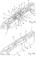
- the Figures 1 - 3 show the central part of the brake caliper 1 of a vehicle disc brake for commercial vehicles.
- the disc brake can be of the sliding caliper type or of the fixed caliper type.
- a brake pad is arranged in each case.
- the brake caliper 1 is provided with a pad well 6, over which a pad retainer 7 extends.
- the lining retainer 7 bridges the lining shaft 6 in such a way that the lining retainer 7 extends across both brake linings, with only the brake lining 3 arranged outside the vehicle being shown in the figures and not the second brake lining arranged inside the vehicle, which can be identical or different .
- the brake lining 3 consists of the actual friction lining 4 and a back plate 5.
- the back plate 5 is preferably made of cast metal.
- the back plate 5 serves to better distribute the brake pressure over the lining surface. In addition, it takes over the management and support of the brake lining either on the brake caliper 1 itself or on a brake carrier that is fixed to the axle.
- the in Figs. 6 and 7 The lining retainer 7 reproduced as a single part is elongated along its center line M and extends for most of its length parallel to the axis of rotation A of the brake disc. Its end inside the vehicle, shown on the right, is attached directly to the brake caliper 1, for which purpose this end of the hold-down device 7 is located in a recess 14 ( Fig. 3a ) of the brake caliper 1 is seated. The other end of the hold-down device 7 shown on the left is only attached indirectly to the brake caliper 1, which will be explained in more detail below.
- the hold-down 7 is designed as a rigid retaining bracket and is combined with a flexurally elastic leaf spring 9 to form a hold-down arrangement.
- the task of the hold-down arrangement is to fix both brake linings in relation to the lining well 6 in such a way that the brake linings cannot protrude or fall out of the lining well 6 radially outwards, based on the axis of rotation A of the brake disc.
- the hold-down 7 has a channel-shaped cross-section over the major part of its total length with a base 7C arranged on the longitudinal center line M of the hold-down, to which side flanks 8A, 8B adjoin along both longitudinal edges of the base, which reinforce this central longitudinal section of the hold-down against bending forces.
- the hold-down device can be supported on the edge of the inner brake lining, not shown in the drawing.
- the flanks 8A, 8B have the shape of sloping slopes.
- the hold-down device 7 has an approximately trapezoidal cross-section over this major part of its length, and in this case it has in particular the cross-section of a trapezoidal channel.
- the flat bottom of the channel formed by the base 7C which has approximately the width of the leaf spring 9, is followed by the side flanks 8A, 8B on both sides at an angle between 15 ° and 90 °, preferably at an angle of 20 °.
- the leaf spring 9 which consists of a spring steel, also extends on the longitudinal center line M. It is fastened with its one spring end in a first spring bearing and with its other spring end in a second spring abutment. Both fastenings can be released in order to remove the spring 9 and the lining retainer 7 arranged below it, and thus to get to the lining shaft 6 from the outside to exchange the brake linings.
- the leaf spring 9 extends on the outside of the hold-down 7 along this, and it is supported from the outside against the hold-down 7, whereby the latter is spring-loaded towards both brake linings. Therefore, the hold-down device 7, although it is itself rigid, is supported by constant spring force against both brake linings and acts on them with a force directed towards the axis of rotation A.
- the leaf spring 9 is supported on the outside of the lining retainer 7 with only a very short longitudinal section. On this short longitudinal section, which is located on a central section of the leaf spring 9 and above the lining shaft 6, the leaf spring is provided with a bend or a kink 9C which extends transversely to the longitudinal extent of the leaf spring 9. The leaf spring 9 rests against the hold-down 7 only with the outside of this bend or this kink 9C. The hold-down device 7 is therefore acted upon by the spring force in the direction of the brake linings 3 only at the location of this discrete system.
- a first spring abutment for the leaf spring 9 is located on the outside of the vehicle next to the lining shaft 6, and a second spring abutment is located on the inside of the vehicle on the brake caliper 1.
- the spring abutment on the outside of the vehicle has a bolt 13 to fix the relevant end 9A of the leaf spring 9.
- the brake caliper 1 is provided with the recess 14, which is open towards the lining shaft 6, in the form of a slot in order to form the second spring abutment. This slot offers space at the same time for the end of the hold-down 7 there and for the end of the leaf spring 9 there.
- the hold-down device 7 is provided with an end face at this end in which a recess 7B can be located ( Fig. 6 ).
- a form-fit element formed on the corresponding end of the leaf spring 9 then engages in the recess 7B.
- This type of longitudinal locking of the leaf spring 9 has the result that as soon as the hold-down 7 is in the opening or recess 14 of the brake caliper 1, the leaf spring 9 is locked in the longitudinal direction, namely axially caught on the hold-down 7. This measure is used for safety and facilitates the subsequent fixing of the hold-down 7 and above all the leaf spring 9 at the other end, that is to say in the area of the spring abutment shown on the left and located outside the vehicle.
- a secure preliminary longitudinal locking of the leaf spring 9 can also be achieved by engaging it with a form-locking element formed on the end of the leaf spring 9 on the inside of the vehicle in an opening 10 which is located directly in the brake caliper 1.
- the opening 10 is here a bore formed transversely to the slot 14 in the brake caliper.
- the hold-down 7 In order to make a contribution on the part of the hold-down 7 to reduce the structural tightness between the rotating vehicle wheel and the non-rotating brake parts, the hold-down is designed in a special way at its end located outside the vehicle, which is explained in more detail below.
- the hold-down device 7 is designed narrower on its end section located outside the vehicle with a width B than on the comparatively longer longitudinal section having the shape of a channel.
- the width B is uniform on this end portion and is no greater than the width of the base 7C.
- the hold-down 7 is provided on this shorter longitudinal section with a crank 11 adjoining the elongated base 7C, in that the hold-down 7, starting from the base 7C, initially has a first downward bend 11A and then a second bend 11B as Has counterbending.
- a straight longitudinal section 12 directly adjoins the second bend 11B, as the end of the hold-down 7 on the outside of the vehicle. In this way, the straight longitudinal section 12 lies lower or closer to the axis of rotation A than the base 7C of the channel-shaped longitudinal section.
- the S-shaped crank 11 is preferably designed so that its second bend 11B, which merges directly into the straight end section 12, does not directly adjoin the first bend 11A, but instead has a short, straight section 11C in between. Its angle to the channel-shaped longitudinal section is 110 °.
- the longitudinal section 12 extends over a length L essentially parallel to the axis of rotation A and offset parallel to the significantly longer, channel-shaped longitudinal section.
- the end section 12 runs offset by 15 to 20 mm from the base 7C of the channel-shaped section
- the area of the crank 11 can be reinforced by one or more stiffening beads 11D, since the hold-down 7 is relatively slim here with the width B, and bending forces can occur.
- the holding-down device 7 preferably consists of stamped and deformed sheet steel with a material thickness of at least 4 mm.
- the crank 11 or the longitudinal section 12 forming the end of the hold-down 7 engages under it without touching it. Nevertheless, this end region of the hold-down device is captured by the bolt 13 arranged above in such a way that it cannot, under any circumstances, detach itself from the brake shaft 6 to the outside.
- the crank 11 or the end section 12 of the hold-down device 7 are at such a height distance from the bolt 13 in the assembled state that there is no contact.
- the hold-down device 7 rests from above on the back plates 5 of both brake linings and is initially only movable in its longitudinal direction there, but is held in a fixed position transversely thereto by means of lateral shaped elements of the brake linings. Both brake linings are freely movable in the lining shaft 6 in the direction of the axis of rotation of the brake disc A and are guided with a certain amount of play in the circumferential direction of the brake disc.
- This combination of freedom of movement means that the hold-down device 7 is mounted on the brake linings 3 in its longitudinal extension freely and transversely with the brake linings 3 so as to be movable or floating to a limited extent.
- the movement in its longitudinal extension is narrowly limited in the assembled state by respective stops on the brake caliper 1.
- the stop surfaces between which the hold-down 7 can move for. B. machined by milling the brake caliper 1.
- the end section 12 is opposed to a projection 15 formed on the brake caliper 1 at a small distance.
- the projection 15 therefore forms a stop which limits the longitudinal mobility of the hold-down device 7 towards the outside of the vehicle.
- the projection 15 preferably extends to close to the circumference of the bolt 13, but without touching the bolt 13.
- Two bearing blocks 50 formed in one piece on the brake caliper 1 each have a bore in which the bolt 13 sits on the axle 13A. So that the bolt 13 cannot detach itself from the bearing blocks 50 and thus from the saddle in the longitudinal direction of the bolt, suitable locking rings, split pins or the like are provided on the bolt 13.
- Figs. 3a - 3c and here in particular Figure 3b show details of the fixing of the vehicle-outer end 9A of the leaf spring 9 on the abutment.
- a component of this spring abutment is a fastening bracket 60 which is connected to the brake caliper 1 by means of the bolt 13 so that it can pivot about the bolt axis 13A.
- the leaf spring 9 is supported with its spring end 9A against the inside or underside of the bracket 60 facing the axis 13A. It can be of additional advantage if a form-fit element formed on this spring end 9A engages in a slot-shaped opening 61 in the bracket 60 and thereby locks the pivoting position of the bracket 60.
- the bracket 60 shown as an individual part is the vehicle-outer abutment element for the leaf spring 9.
- the bracket 60 consists of a central section 62 parallel to the axis 13A, on which the opening 61 can be located, and two side sections arranged approximately at right angles with respect to the central section 62 63 together. These side sections are designed as tabs 63 and each provided with a round opening 66 arranged on the axis 13A. Since the two openings 66 are aligned with one another on the axis 13A, the axis 13A is at the same time the axis of alignment of the two openings 66. The bolt 13 passes through both openings at the same time.
- the edge of the tabs 63 facing the disc brake axis of rotation A has an edge contour 64 which is curved towards the axis 13A.
- the contour section of the contour 64 facing the disc brake axis A forms a stop, since the contour course is such that the contour 64 is partly at a greater distance A1 and partly at a smaller distance A2 from the axis 13A.
- the contour 64 can be eccentric or it can be circular arc-shaped, but then with an offset to the axis 13A.
- the bolt 13 is the fastening means to detachably fasten the bracket 60, which serves as an abutment element and as a blocking element, to the brake caliper 1.
- the end 9A of the leaf spring 9 rests under spring tension against the inside of the central section 62 facing the bolt 13. This inside is therefore the abutment 62A on which the spring 9 is supported with its spring end. The sum of these measures leads to the securing and maintenance of the bending stress in the leaf spring 9.
- An additional safety measure can be the form-fitting engagement of an angled form-fitting element additionally formed on the spring end 9A in the opening 61 of the bracket 60.
- the spring 9 can be bent upwards at this spring end, so that the outside of this bend faces the bolt axis 13A.
- the assembly of the assembly consisting of pad hold-down 7, leaf spring 9, bolt 13 and bracket 60 as an abutment element and locking element is done by first placing the other end of the leaf spring 9 on the hold-down 7 so that it engages behind the end of the hold-down 7 inside the vehicle .
- the parts, the hold-down device and the leaf spring, which are temporarily connected in this way, are then pushed in the longitudinal direction into the recess 14 in the brake caliper 1.
- the bracket 60 is placed on the other spring end 9A, which can be facilitated by the engagement of the form-fit element in the opening 61 of the bracket 60 and thus becomes even safer for the fitter.
- the end 9A of the spring 9 is supported on the abutment 62A on the inside of the bracket 60.
- the bracket 60 is moved downwards by manual pressure and by bending the leaf spring until the bolt 13 can be inserted into the bearing blocks 50 along the axis 13A.
- the exertion of pressure on the bracket 60 can then be ended, since the tension force of the leaf spring 9 is now safely absorbed by the bracket 60, which forms the abutment element, in conjunction with the bolt 13.
- the leaf spring 9 holds the hold-down device 7 on the brake linings 3 with spring preloading force and ensures that in the event of a stronger impact, e.g. B. due to a pothole passage, the radially outward lifting brake pad 3 is pushed back into its original position. Should the leaf spring 9 by z. B. break mechanical influences and thus lose their holding function, the hold-down device 7 is still held so securely by the bracket 60 arranged above and the recess 14 that the brake pads cannot be lost.
- crank 11 shown on the outside of the vehicle of the brake disc, narrower longitudinal section of the hold-down device 7 has the advantage that in this area disc brake parts protrude less radially outward and thus contribute to the structural constriction to the surrounding rotating around the brake To defuse vehicle wheel.
- the crank 11 leads to a space requirement in the area of the brake lining 3 arranged on the vehicle-outer side of the brake disc. This is therefore designed in a special way, which is explained in more detail below.
- the brake lining 3 arranged on the outside of the vehicle is composed of the friction lining 4 intended to rest against the brake disc and the stable back plate 5.
- the latter consists e.g. B. made of cast steel, the front side being designed as a fastening surface 16 for the friction lining 4, while the rear side 17 is designed as a pressure surface for transmitting the brake pressure. Because with this rear side 17, the back plate 5 rests against a corresponding pressure-exerting surface 18 of the brake caliper 1.
- the surface 18 is at the same time a wall of the covering shaft 6.
- the circumferential contour of the back plate 5 is determined by an upper or, with respect to the axis of rotation A, outer edge 21, an inner or lower edge 22 facing the axis of rotation A and two side edges 23A, 23B extending between the upper and lower edge, which run parallel to each other.
- the upper or outer edge 21 is characterized by a main course which takes up the shape of the brake disc. To this end, the upper edge 21 shows mainly, i. H. on its predominant length, an arc-shaped course, which takes over the circular shape on the circumference of the round brake disc. This has the advantage that the brake lining 3 does not protrude radially outward beyond the technically required circumference of the brake disk.
- the back plate 5 is supported in the circumferential direction with the two side edges 23A, 23B, so that the braking torques are transmitted to the brake caliper 1 or, alternatively, to a brake carrier of the disc brake that is fixed to the axis. To a lesser extent, the braking torques can also be transmitted via the lower edge 22 of the back plate 5.
- the friction lining 4 is also distinguished on its upper or outer edge 31 by a main course which takes up the shape of the brake disc.
- the upper edge 31 shows mainly, i. H. on its predominant length, an arc-shaped course, which takes on the circular shape on the circumference of the round brake disc, whereby this edge does not protrude radially outward beyond the circumference of the brake disc, but at the same time a maximum of contact area is available between friction lining 4 and brake disc.
- edges 21, 31 have a basically arched course, this includes individual deviations from this main design.
- a narrow recess 33 can be arranged eccentrically in the friction lining 4 and back plate 5, which is used to fasten an electrical brake lining wear sensor there.
- individual small projections can be formed on the edge 21 without impairing the main arcuate shape of the edge, which can be advantageous, for example, in the context of the production of the brake lining.
- the main course of the upper edge 21 of the back plate 5 is interrupted exactly in the middle between the two side edges 23A, 23B by a partial lowering 25 of the edge 21.
- the depression 25 is wider than the width B of the angled hold-down section.
- the friction lining 4 also has a free space in the same area. This is because, while the friction lining 4 is otherwise mainly curved on its outer edge 31, this primary design is also interrupted in the middle between the two side edges 23A, 23B by a depression 35 of the upper edge 31.
- the depression 35 also leads to a free space on the circumferential contour of the friction lining 4, through which the hold-down 7 extends with at least part of its cross section. For this purpose, the depression 35 is wider than the width B of the cranked hold-down section.
- the bottom of the depression 25 in the back plate 5 is lower and thus closer to the axis of rotation A than those sections 31A, 31B of the upper edge 31 of the Friction lining 4, which directly adjoin the depression 35 formed in the friction lining 4 in the circumferential direction.
- the lowering 25 therefore creates free space for the hold-down device to cross.
- the hold-down 7 occupies a position less far radially outwards on this part of its length, which reduces the risk caused by the structural tightness between the components of the disc brake and the vehicle wheel rotating around the brake, that brake parts will drag on the inside of the rotating Vehicle wheel is coming.
- a projection 40 is formed in one piece on the rear side 17 of the back plate 5, below its upper edge 21.
- the extension 40 is arranged closer to the upper edge 21 than to the lower edge 22 of the back plate 5. It is positioned centrally in the circumferential direction of the brake lining 3, that is to say has the same distance from both side edges 23A, 23B.
- a correspondingly designed surface of the brake caliper 1 with at least one downwardly directed support surface 42 ( Figure 3c ) Mistake. This is at right angles to the rear side 17 of the back plate 5 and is supported on the bottom of a recess 38 ( Figure 4b ) with which the brake caliper 1 is provided.
- the extension 40 has a square plan.
- the two outer corners 41 of the projection 40 spaced apart from the rear side 17 are each rounded, with a corner radius R of at least 4 mm each.
- the rounding of the corners 41 has manufacturing advantages with regard to the machining of the corresponding recess 38 in the brake caliper 1 ( Figure 4b ).
- This recess 38 serves as a lining receptacle in that it accommodates at least part of the shoulder 40 of the brake lining, and for this purpose it is provided with correspondingly rounded inner corners 39 of at least 4 mm corner radius.
- the hold-down surface 43 is lower and thus closer to the axis of rotation A than the depression 25.
- the hold-down 7 is supported against the brake lining only on the hold-down surface 43, namely with the lower side of the short one following the crank 11, which forms a support surface 12A Longitudinal section 12.
- the longitudinal section 12 is also the end section of the hold-down device. Its end face is opposite a transverse wall of that recess 38 of the brake caliper 1, which at least partially receives the extension 40.
- a comparatively shorter transition surface 44 adjoins the hold-down surface 43 for the abutment of the hold-down device 7 towards the friction lining 4.
- the transition surface 44 rises to the bottom of the depression 25, for example in the form of a bend or, alternatively, an inclined ramp.
- the transition surface 44 meets the bottom of the depression 25 at an edge 45, according to FIG Figure 3c this edge 45 is arranged in a plane of the back plate 5 which is located between the plane of the fastening surface 16 and the plane of the rear side 17.
- the end section 12 of the hold-down 7 supported on the hold-down surface 43 is therefore flanked by the two raised edge regions 47, as a result of which the hold-down 7 has little or no lateral play in relation to the brake lining 3.
- bracket 60 When the bracket 60 is mounted, it is not only an abutment element for the leaf spring 9, but it is also a blocking element at the same time. This is because the edge contours 64 of the tabs 63 form a stop which is not, or is only slightly, spaced from the opposing surfaces formed on the extension 40. This has the consequence that no or only a slight lifting of the brake lining 3 with its support surface 42 from the brake caliper is possible.
- the aforementioned locking effect is achieved in that a groove 48 is formed in each of the two edge regions 47 of the projection 40, which forms the counter-stop.
- each channel 48 extends along the respective side surface 49 of the attachment 40.
- the bottom of each channel 48 faces the bolt 13 and is either at a short distance from the respective contour 64 of the bracket 60, or there is even permanent contact between the contour 64 and the bottom of the channel 48. If there is no permanent contact, however, the distance is in any case small and, above all, less than the distance between the bolt 13 and the crank 11 or the end section 12 of the hold-down device 7.
- the contours 64 on the bracket 60 serving as a locking element therefore each form a stop, and the grooves 48 on the brake lining 3 each form the counter-stop. Should Therefore, the brake lining 3 hit upwards due to strong vibrations, which leads to an equally large lifting of the hold-down device 7, this movement is blocked at the latest when the channel 48 hits the contour 64. An even greater movement, which would then have to be completely absorbed by the leaf spring 9, is prevented and the life of the leaf spring 9 is thus extended.
- the channels 48 can be designed to be open along their one side, namely towards the respective side surface 49 of the extension 40.
- the channels 48 can be open at their end facing away from the back plate 5. Facing the back plate 5, they are of such a length that they not only extend over the depth of the extension 40, but also into the thickness of the back plate 5. This makes it possible for the stop formed by the contour 64 of the side sections 63 to be close to the back plate 5. This minimizes or even prevents a tilting moment in the event of a strike on the brake lining 3.
- the contour 64 is semicircularly curved, the center of the radius of the curvature being offset from the bolt axis 13A.
- the contour 64 is designed like a cam or an eccentric.
- a further embodiment of the bracket 60 is shown, here in individual assembly steps.
- the edges 64 formed on the bracket 60 are again designed in a pronounced cam or eccentric shape.
- the end 9A of the spring 9 on the outside of the vehicle is fixed by pivoting the bracket 60 already mounted on the bolt 13 according to the pivoting arrow by approximately 90 ° about the bolt axis 13A. This causes the end 9A of the spring to pass under the abutment 62A located on the central portion 62 of the bracket.
- the bracket 60 here forms a locking element which is held in its locking position in a spring-loaded manner by the supporting spring 9, which is shown in FIG Fig. 10 is reproduced below.
- the bracket 60 is acted upon by the spring 9 supported on its middle section 62 with a pivoting force which tends to move the stop 64 formed on the bracket towards the counter-stop 48 formed on the brake lining.
- This is achieved in that the inside of the central section 62, which faces the bolt 13 and on which the abutment 62A is located, is bent.
- This leads to a force component which endeavors, on the one hand, to always secure the bracket 60 against pivoting back, and, on the other hand, to always move the stop 64 formed thereon towards the counter-stop 48.
- the stop 64 rests against the counterstop 48 under spring force so that the brake lining 3 rests against the brake caliper 1 with a force acting in the radial direction and / or in the direction axially pointing away from the brake disc.
- Figures 9a-9c show a comparable design of the middle section 62 of the bracket 60, in which the abutment 62A shows a curved course, so that pivoting back of the bracket 60 against the pivoting arrow is practically impossible.
- An additional, form-fitting securing of the spring end against the bracket 60 is not required in this case.
- the hold-down device 7 is only slightly spaced from the leaf spring 9, which is supported in the slot-shaped recess 14 on the brake caliper.
- the inner of the two brake linings can only lift slightly from its radial support surface due to the action of the hold-down device 7.
- the hold-down device 7 at its other end located inside the vehicle, with which it is supported from above on the back plate of the inner brake lining, is designed in such a way that this hold-down end is supported against the brake caliper 1 in the circumferential direction.
- the hold-down 7 is provided at this end with a central section 70 extending on its longitudinal center line M and continuing the base 7C, as well as with a side section 71 or 72 on each side of the central section 70.
- the side sections 71, 72 are located in the extension of the side flanks 8A, 8B of the hold-down section designed as a channel and, viewed in the longitudinal direction of the hold-down, have an upwardly curved, hook-shaped course.
- an inner surface 77 arranged above the plane of the base 7C is formed on each side section 71, 72.
- the two inner surfaces 77 face one another in such a way that there is a free space between them.
- the support on the mating surfaces 81 can take place without play, or with a side play limited in the circumferential direction of the brake disk.
- the side sections 71, 72 are each separated from the middle section 70 by a longitudinal slot 73, 74, which is only open to the nearest end of the hold-down Cut. Only the middle section 70 protrudes into the slot 14, whereas the side sections 71, 72 are located outside the slot.
- the corresponding opposing surfaces 81 facing away from one another are formed on the brake caliper 1 above or, alternatively, below the slot 14 ( Fig. 2 ).
- the Fig. 11 shows a different design, on the one hand, of the hold-down device 7 and, on the other hand, of the extension formed on the back plate 5 of the brake lining.
- This is designed in two parts here, with a free space between the two sub-extensions 40.
- Both lugs or partial lugs 40 are each provided with a hold-down surface 43 angled at an angle to their support surface 42 on the underside, the two hold-down surfaces 43 together forming a "V".
- the angle of the hold-down surfaces 43 to the respective support surface 42 is between 30 ° and 60 °.
- the two approaches 40 jointly describe an essentially quadrangular floor plan, the two outer corners 41 of this floor plan spaced apart from the rear side 17 of the back plate 5 being rounded with corner radii R of at least 4 mm. In this way, these approaches 40 also fit into the in Figure 4b reproduced recess 38 of the brake caliper 1.
- the lowered end section 12 of the hold-down device 7 is composed of a base 12C and 12 adjoining the crank 11 sloping flanks on both sides of the base 12C.
- the undersides of these obliquely rising flanks each form a support surface 12A with which the hold-down 7 is supported on the brake lining.
Landscapes
- Engineering & Computer Science (AREA)
- General Engineering & Computer Science (AREA)
- Mechanical Engineering (AREA)
- Braking Arrangements (AREA)
Description
Die Erfindung betrifft eine Scheibenbremse mit einem Bremssattel, der eine Bremsscheibe und zu deren beiden Seiten in einem Belagschacht angeordnete Bremsbeläge übergreift, und mit einem quer über die Bremsbeläge führenden Niederhalter, der zu der Scheibenbremsachse hin gegen die Bremsbeläge abgestützt ist und mit seinem einen Ende in einem Schlitz des Bremssattels sitzt, wobei das stirnseitige Ende des Niederhalters einer Rückwand, und eine Ober- und eine Unterseite des Niederhalters einer oberen bzw. einer unteren Fläche des Schlitzes gegenüberliegt, und wobei der Niederhalter mit einem sich in den Schlitz erstreckenden Mittelabschnitt und mit einem Seitenabschnitt zu jeder Seite des Mittelabschnitts versehen ist, sich die Seitenabschnitte außerhalb des Schlitzes befinden, an jedem Seitenabschnitt eine Innenfläche ausgebildet ist, und die Innenflächen zur Ausbildung von Abstützflächen einander zugewandt sind.The invention relates to a disc brake with a brake caliper which overlaps a brake disc and brake linings arranged in a lining shaft on both sides, and with a hold-down device which leads across the brake linings and which is supported towards the disc brake axis against the brake linings and with one end in a slot of the brake caliper sits, wherein the front end of the hold-down a rear wall, and a top and a bottom of the hold-down an upper and a lower surface of the slot opposite, and wherein the hold-down with a central portion extending into the slot and with a Side portion is provided on each side of the central portion, the side portions are outside the slot, an inner surface is formed on each side portion, and the inner surfaces face one another to form support surfaces.
Die Erfindung betrifft ferner einen Niederhalter für die Befestigung von Bremsbelägen in einer Scheibenbremse mit einer Längserstreckung und einer demgegenüber geringeren Breite, wobei der Niederhalter auf einem großen Teil seiner Gesamtlänge eine Querschnittsgestalt aufweist, und auf einem anderen Teil seiner Gesamtlänge einen Endbereich mit einer anderen Querschnittsgestalt aufweist, und in dem Endbereich mit einem auf der Längsmittellinie des Niederhalters angeordneten Mittelabschnitt und mit einem Seitenabschnitt zu jeder Seite des Mittelabschnitts versehen ist, wobei an jedem Seitenabschnitt eine Innenfläche ausgebildet ist, und die Innenflächen zur Ausbildung von Abstützflächen einander zugewandt sind.The invention also relates to a hold-down device for fastening brake linings in a disc brake with a longitudinal extent and a smaller width, the hold-down device having a cross-sectional shape over a large part of its total length and an end region with a different cross-sectional shape on another part of its total length , and is provided in the end region with a central portion arranged on the longitudinal center line of the hold-down device and with a side portion on each side of the central portion, an inner surface being formed on each side portion, and the inner surfaces facing one another to form support surfaces.
Aus der
Eine gattungsgemäße Scheibenbremse mit den Merkmalen des Oberbegriffs ist aus der
Der Erfindung liegt daher die Aufgabe zugrunde, die bremssattelseitige Festlegung des Niederhalters fertigungstechnisch einfacher zu gestalten.The invention is therefore based on the object to design the brake caliper side of the hold-down produced more easily.
Hierzu wird bei einer Scheibenbremse mit den eingangs angegebenen Merkmalen vorgeschlagen, dass die Innenflächen ober- oder unterhalb des Schlitzes gegen den Bremssattel gerichtet sind. Vorzugsweise ist der Schlitz in seitlicher Richtung des Niederhalters jeweils völlig offen, was die Bearbeitung der oberen Fläche, der unteren Fläche und der Rückwand des Schlitzes durch ein spannendes Fertigungsverfahren erleichtert. Diese Bearbeitung kann z. B. mit einem einzigen Werkzeug und insbesondere einem Fräser, in einem einzigen Durchgang erfolgen.For this purpose, in the case of a disc brake with the features specified at the beginning, it is proposed that the inner surfaces be directed towards the brake caliper above or below the slot. The slot is preferably completely open in the lateral direction of the hold-down device, which facilitates the machining of the upper surface, the lower surface and the rear wall of the slot by an exciting manufacturing process. This processing can e.g. B. with a single tool and in particular a milling cutter, done in a single pass.
Hinsichtlich des erfindungsgemäßen Niederhalters wird vorgeschlagen, dass die Innenflächen ober- oder unterhalb der Ebene des Mittelabschnitts angeordnet sind.With regard to the hold-down device according to the invention, it is proposed that the inner surfaces are arranged above or below the plane of the central section.
Der Niederhalter ist damit so ausgestaltet, dass seine Abstützung in Umfangsrichtung der Bremsscheibe nicht innerhalb einer Ausnehmung in dem Bremssattel erfolgt, sondern diese Abstützung außerhalb der Ausnehmung an einer Gegenfläche des Bremssattels erfolgt. Diese Gegenfläche befindet sich außen oberhalb oder alternativ auch unterhalb des in dem Bremssattel ausgebildeten Schlitzes. Insgesamt wird damit eine fertigungstechnisch einfache und wenig Platz beanspruchende Lösung für eine spielfreie oder ein begrenztes Spiel zulassende Festlegung des Niederhalters in Bremsscheiben-Umfangsrichtung erzielt.The hold-down device is thus designed in such a way that its support in the circumferential direction of the brake disc does not take place within a recess in the brake caliper, but this support takes place outside the recess on a counter surface of the brake caliper. This mating surface is located on the outside above or, alternatively, below the slot formed in the brake caliper. Overall, a solution which is simple in terms of production engineering and takes up little space is achieved for a fixation of the hold-down device in the circumferential direction of the brake disc that is free of play or allows limited play.
Vorteilhafte Ausgestaltungen der Scheibenbremse und des Niederhalters sind in den jeweiligen Unteransprüchen angegeben. Ausführungsbeispiele werden im Folgenden anhand der Zeichnungen näher erläutert. Darin zeigen:
- Fig. 1
- eine perspektivische Darstellung des Bremssattels einer Fahrzeug-Scheibenbremse einschließlich des im Bremssattel ausgebildeten Belagschachts mit einem darin angeordneten Bremsbelag, sowie einer Niederhalteranordnung über dem Belagschacht;
- Fig. 2
- die Gegenstände nach
Fig. 1 in einer anderen perspektivischen Darstellung, jedoch ohne alle Teile der inFig. 1 komplett wiedergegebenen Niederhalteranordnung; - Fig. 3a
- die Gegenstände nach
Fig. 1 in einem mittig angelegten Längsschnitt durch den Sattel; - Fig. 3b
- die Gegenstände nach
Fig. 1 in einem anderen, hier nicht mittig angelegten Längsschnitt durch den Sattel; - Fig. 3c
- den linken Bereich der
Fig. 3a in größerem Maßstab; - Fig. 4a
- den linken Bereich der
Fig. 2 in größerem Maßstab; - Fig. 4b
- denselben Bereich wie
Fig. 4a , allerdings bei fehlendem Bremsbelag; - Fig. 5
- eine perspektivische Darstellung nur des Bremsbelags mit dem Betrachter zugewandter Rückenplatte;
- Fig. 6
- eine perspektivische Darstellung nur des an dem Bremssattel verwendeten Niederhalters der Niederhalteranordnung;
- Fig. 7
- den Niederhalter in einer Seitenansicht;
- Fig. 8
- eine perspektivische Darstellung nur des an dem Bremssattel verwendeten Bügels, welcher zugleich als Widerlagerelement und als Sperrelement dient;
- Fig. 9a - 9c
- drei verschiedene Varianten des Bügels und deren Zusammenwirken mit dem Bremsbelag;
- Fig. 10
- in vier verschiedenen Schritten das Befestigen der Blattfeder, und
- Fig. 11
- eine andere Ausführungsform des Niederhalters und des Bremsbelags.
- Fig. 1
- a perspective view of the brake caliper of a vehicle disc brake including the lining well formed in the brake caliper with a brake lining arranged therein, and a hold-down arrangement above the lining well;
- Fig. 2
- the items after
Fig. 1 in a different perspective view, but without all parts of the inFig. 1 completely reproduced hold-down arrangement; - Fig. 3a
- the items after
Fig. 1 in a central longitudinal section through the saddle; - Figure 3b
- the items after
Fig. 1 in another longitudinal section through the saddle, not in the middle; - Figure 3c
- the left area of the
Fig. 3a on a larger scale; - Figure 4a
- the left area of the
Fig. 2 on a larger scale; - Figure 4b
- same area as
Figure 4a , but with missing brake lining; - Fig. 5
- a perspective view of only the brake pad with the viewer facing back plate;
- Fig. 6
- a perspective view of only the hold-down device used on the brake caliper of the hold-down device;
- Fig. 7
- the hold-down device in a side view;
- Fig. 8
- a perspective view of only the bracket used on the brake caliper, which serves both as an abutment element and as a locking element;
- Figures 9a-9c
- three different variants of the bracket and their interaction with the brake lining;
- Fig. 10
- attaching the leaf spring in four different steps, and
- Fig. 11
- another embodiment of the hold-down device and the brake lining.
Die
Der Bremsbelag 3 besteht wie üblich aus dem eigentlichen Reibbelag 4 sowie einer Rückenplatte 5. Die Rückenplatte 5 besteht vorzugsweise aus Gussmetall. Die Rückenplatte 5 dient der besseren Verteilung des Bremsdrucks über die Belagfläche. Außerdem übernimmt sie die Führung und die Abstützung des Bremsbelags entweder an dem Bremssattel 1 selbst, oder an einem achsfesten Bremsträger.As usual, the
Der in
Zur Sicherung der beiden Bremsbeläge in dem Belagschacht 6 ist der Niederhalter 7 als ein starrer Haltebügel ausgebildet, und mit einer biegeelastischen Blattfeder 9 zu einer Niederhalteranordnung kombiniert. Aufgabe der Niederhalteranordnung ist es, beide Bremsbeläge so gegenüber dem Belagschacht 6 zu fixieren, dass die Bremsbeläge nicht nach radial außen, bezogen auf die Drehachse A der Bremsscheibe, aus dem Belagschacht 6 heraustreten oder herausfallen können.To secure the two brake linings in the lining well 6, the hold-
Der Niederhalter 7 ist auf dem überwiegenden Teil seiner Gesamtlänge von rinnenförmigem Querschnitt mit einer auf der Längsmittellinie M des Niederhalters angeordneten Basis 7C, an die sich längs beider Längsränder der Basis Seitenflanken 8A, 8B anschließen, die diesen zentralen Längsabschnitt des Niederhalters gegenüber Biegekräften verstärken.The hold-
Mit den Seitenflanken 8A, 8B kann sich der Niederhalter auf dem Rand des innenliegenden, auf der Zeichnung nicht dargestellten Bremsbelags abstützen. Hierzu kann es von Vorteil sein, wenn die Flanken 8A, 8B die Gestalt ansteigender Schrägen aufweisen. In diesem Fall weist der Niederhalter 7 auf diesem größten Teil seiner Länge einen in etwa trapezförmigen Querschnitt auf, und er weist in diesem Fall insbesondere den Querschnitt einer trapezförmigen Rinne auf.With the side flanks 8A, 8B, the hold-down device can be supported on the edge of the inner brake lining, not shown in the drawing. For this purpose it can be advantageous if the
An den durch die Basis 7C gebildeten, flachen Boden der Rinne, welcher in etwa die Breite der Blattfeder 9 aufweist, schließen sich zu beiden Seiten die Seitenflanken 8A, 8B in einem Winkel zwischen 15° und 90° an, vorzugsweise in einem Winkel von 20°.The flat bottom of the channel formed by the
Die aus einem Federstahl bestehende Blattfeder 9 erstreckt sich ebenfalls auf der Längsmittellinie M. Sie ist mit ihrem einen Federende in einem ersten Federlager, und mit ihrem anderen Federende in einem zweiten Federwiderlager befestigt. Beide Befestigungen sind lösbar, um die Feder 9 und den darunter angeordneten Belagniederhalter 7 zu entfernen, und so zum Austausch der Bremsbeläge von außen her an den Belagschacht 6 zu gelangen.The
Die Blattfeder 9 erstreckt sich auf der Außenseite des Niederhalters 7 längs zu diesem, und sie ist von außen her gegen den Niederhalter 7 abgestützt, wodurch dieser zu beiden Bremsbelägen hin federbelastet ist. Daher stützt sich der Niederhalter 7, obwohl selbst starr, unter dauernder Federkraft gegen beide Bremsbeläge ab und beaufschlagt diese jeweils mit einer zu der Drehachse A hin gerichteten Kraft.The
Die Blattfeder 9 stützt sich nur mit einem sehr kurzen Längsabschnitt außen an dem Belagniederhalter 7 ab. Auf diesem kurzen Längsabschnitt, der sich auf einem Mittelabschnitt der Blattfeder 9 und über dem Belagschacht 6 befindet, ist die Blattfeder mit einer Biegung bzw. einem Knick 9C versehen, der sich quer zur Längserstreckung der Blattfeder 9 erstreckt. Nur mit der Außenseite dieser Biegung bzw. dieses Knicks 9C liegt die Blattfeder 9 an dem Niederhalter 7 an. Nur am Ort dieser diskreten Anlage wird daher der Niederhalter 7 mit der Federkraft in Richtung auf die Bremsbeläge 3 beaufschlagt.The
Ein erstes Federwiderlager für die Blattfeder 9 befindet sich fahrzeugaußen neben dem Belagschacht 6, ein zweites Federwiderlager fahrzeuginnen am Bremssattel 1. Das fahrzeugäußere Federwiderlager weist für die Festlegung des betreffenden Endes 9A der Blattfeder 9 einen Bolzen 13 auf. Hingegen ist der Bremssattel 1 zur Bildung des zweiten Federwiderlagers mit der zu dem Belagschacht 6 hin offenen Ausnehmung 14 in Gestalt eines Schlitzes versehen. Dieser Schlitz bietet Platz zugleich für das dortige Ende des Niederhalters 7 wie auch für das dortige Ende der Blattfeder 9.A first spring abutment for the
Für die Montage der Anordnung aus Niederhalter 7 und Blattfeder 9 kann es von Vorteil sein, wenn die gemeinsam in die schlitzförmige Ausnehmung 14 des Bremssattels 1 eingesetzten Enden dieser beiden Bauteile in Längsrichtung zueinander verriegelt sind. Hierzu ist der Niederhalter 7 an diesem Ende mit einer Stirnfläche versehen, in der sich eine Ausnehmung 7B befinden kann (
Alternativ ist eine sichere vorläufige Längsverriegelung der Blattfeder 9 auch erreichbar, indem diese mit einem an dem fahrzeuginneren Ende der Blattfeder 9 ausgebildeten Formschlusselement in eine Öffnung 10 eingreift, die sich unmittelbar in dem Bremssattel 1 befindet. Die Öffnung 10 ist hier eine quer zu dem Schlitz 14 im Bremssattel ausgebildete Bohrung.Alternatively, a secure preliminary longitudinal locking of the
Um seitens des Niederhalters 7 einen Beitrag zu leisten, die bauliche Enge zwischen dem rotierenden Fahrzeugrad und den nichtrotierenden Bremsenteilen zu mindern, ist der Niederhalter an seinem fahrzeugaußen gelegenen Ende in besonderer Weise gestaltet, was im Folgenden näher erläutert wird.In order to make a contribution on the part of the hold-
Gemäß den
Vorzugsweise ist die S-förmige Kröpfung 11 so ausgestaltet, dass deren zweite Biegung 11B, welche unmittelbar in den geraden Endabschnitt 12 übergeht, nicht unmittelbar an die erste Biegung 11A anschließt, sondern sich dazwischen noch ein kurzer, gerade verlaufender Abschnitt 11C befindet. Dessen Winkel zu dem rinnenförmigen Längsabschnitt beträgt 110°.The S-shaped
Der Längsabschnitt 12 erstreckt sich auf einer Länge L im Wesentlichen parallel zu der Drehachse A und parallel versetzt zu dem deutlich längeren, rinnenförmigen Längsabschnitt. Bei dem Ausführungsbeispiel, bei dem der Niederhalter 7 eine Gesamtlänge von etwa 150 mm aufweist, verläuft der Endabschnitt 12 um 15 bis 20 mm versetzt zu der Basis 7C des rinnenförmigen AbschnittsThe
Der Bereich der Kröpfung 11 kann durch eine oder mehrere Versteifungssicken 11D verstärkt sein, da der Niederhalter 7 hier mit der Breite B relativ schlank ist, und Biegekräfte auftreten können. Vorzugsweise besteht der Niederhalter 7 aus gestanztem und verformtem Stahlblech mit einer Materialdicke von mindestens 4 mm.The area of the
Bei montiertem Bolzen 13 wird dieser von der Kröpfung 11 oder dem das Ende des Niederhalters 7 bildenden Längsabschnitt 12 ohne Berührungskontakt untergriffen. Trotzdem ist dieser Endbereich des Niederhalters durch den oberhalb angeordneten Bolzen 13 so gefangen, dass er sich unter keinen Umständen nach außen von dem Bremsschacht 6 lösen kann. Die Kröpfung 11 bzw. der Endabschnitt 12 des Niederhalters 7 weisen im montierten Zustand einen solchen Höhenabstand zu dem Bolzen 13 auf, dass es zu keinem Kontakt kommt.When the
Der Niederhalter 7 liegt von oben her auf den Rückenplatten 5 beider Bremsbeläge auf und ist dort zunächst nur in seiner Längsrichtung beweglich, hingegen quer dazu mittels seitlicher Formelemente der Bremsbeläge fixiert gehalten. Beide Bremsbeläge sind im Belagschacht 6 in Richtung der Drehachse der Bremsscheibe A frei beweglich und in Umfangsrichtung der Bremsscheibe mit einem gewissen Spiel geführt. Diese Kombination von Bewegungsfreiheiten führt dazu, dass der Niederhalter 7 an den Bremsbelägen 3 in seiner Längserstreckung frei und quer mit den Bremsbelägen 3 beschränkt beweglich bzw. schwimmend gelagert ist. Die Bewegung in seiner Längserstreckung wird in montiertem Zustand durch jeweilige Anschläge am Bremssattel 1 eng begrenzt. Hierzu sind die Anschlagflächen, zwischen denen sich der Niederhalter 7 bewegen kann, z. B. durch Fräsen des Bremssattels 1 mechanisch bearbeitet.The hold-down
In Längsrichtung des Niederhalters 7 steht dessen Endabschnitt 12 ein an dem Bremssattel 1 angeformter Vorsprung 15 mit geringem Abstand gegenüber. Der Vorsprung 15 bildet daher einen Anschlag, welcher die Längsbeweglichkeit des Niederhalters 7 nach fahrzeugaußen hin begrenzt.In the longitudinal direction of the hold-down
Vorzugsweise erstreckt sich der Vorsprung 15 bis nahe an den Umfang des Bolzens 13, allerdings ohne den Bolzen 13 zu berühren.The
Zwei einstückig an dem Bremssattel 1 angeformte Lagerböcke 50 weisen je eine Bohrung auf, in der der Bolzen 13 auf der Achse 13A sitzt. Damit sich der Bozen 13 nicht in Bolzenlängsrichtung aus den Lagerböcken 50 und damit aus dem Sattel lösen kann, sind an dem Bolzen 13 geeignete Sicherungsringe, Splinte oder dergleichen vorgesehen.Two bearing blocks 50 formed in one piece on the
Die
Der in
Der der Scheibenbremsdrehachse A zugewandte Rand der Laschen 63 weist eine Randkontur 64 auf, die zu der Achse 13A hin gekrümmt ist. Der der Scheibenbremsachse A zugewandte Konturabschnitt der Kontur 64 bildet einen Anschlag, da der Konturverlauf dergestalt ist, dass die Kontur 64 teils einen größeren Abstand A1, teils einen geringeren Abstand A2 zu der Achse 13A aufweist. Zum Beispiel kann die Kontur 64 exzenterförmig sein oder sie kann kreisbogenförmig sein, dann allerdings mit Versatz zu der Achse 13A.The edge of the
Der Bolzen 13 ist das Befestigungsmittel, um den als Widerlagerelement und als Sperrelement dienenden Bügel 60 lösbar an dem Bremssattel 1 zu befestigen. Zugleich liegt das Ende 9A der Blattfeder 9 unter Federspannung an der dem Bolzen 13 zugewandten Innenseite des Mittelabschnitts 62 an. Diese Innenseite ist daher das Widerlager 62A, an dem sich die Feder 9 mit ihrem Federende abstützt. Die Summe dieser Maßnahmen führt zur Sicherung und Aufrechterhaltung der Biegespannung in der Blattfeder 9.The
Eine zusätzliche Sicherungsmaßnahme kann das formschlüssige Eingreifen eines an dem Federende 9A zusätzlich ausgebildeten, abgewinkelten Formschlusselements in die Öffnung 61 des Bügels 60 sein. Zu diesem Zweck kann die Feder 9 an diesem Federende nach oben gebogen sein, so dass die Außenseite dieser Biegung der Bolzenachse 13A zugewandt ist.An additional safety measure can be the form-fitting engagement of an angled form-fitting element additionally formed on the
Die Montage der Anordnung bestehend aus Belagniederhalter 7, Blattfeder 9, Bolzen 13 und Bügel 60 als Widerlagerelement und Sperrelement erfolgt, indem zunächst die Blattfeder 9 mit ihrem anderen Ende so auf den Niederhalter 7 gelegt wird, dass sie hinter das fahrzeuginnere Ende des Niederhalters 7 greift. Sodann werden die so vorläufig verbundenen Teile Niederhalter und Blattfeder in Längsrichtung in die Ausnehmung 14 in dem Bremssattel 1 hineingeschoben.The assembly of the assembly consisting of pad hold-
In einem nächsten Schritt wird auf das andere Federende 9A der Bügel 60 aufgesetzt, was durch das Eingreifen des Formschlusselements in die Öffnung 61 des Bügels 60 erleichtert werden kann und so für den Monteur noch sicherer wird. Das Ende 9A der Feder 9 stützt sich dabei an dem Widerlager 62A innen an dem Bügel 60 ab. Nun wird nur der Bügel 60 durch manuellen Druck und unter Biegen der Blattfeder nach unten bewegt, bis sich der Bolzen 13 längs der Achse 13A in die Lagerböcke 50 einsetzen lässt. Sodann kann die Druckausübung auf den Bügel 60 beendet werden, da nunmehr die Spannkraft der Blattfeder 9 durch den das Widerlagerelement bildenden Bügel 60 in Verbindung mit dem Bolzen 13 sicher aufgenommen wird.In a next step, the
Nach radial außen hin hält die Blattfeder 9 mit Federvorspannkraft den Niederhalter 7 auf den Bremsbelägen 3 und sorgt dafür, dass bei einem stärkeren Stoß, z. B. aufgrund einer Schlaglochdurchfahrt, der nach radial außen abhebende Bremsbelag 3 wieder in seine Ursprungsposition gedrückt wird. Sollte die Blattfeder 9 durch z. B. mechanische Einflüsse brechen und damit ihre Haltefunktion verlieren, ist der Niederhalter 7 durch den darüber angeordneten Bügel 60 und die Ausnehmung 14 immer noch so sicher gehalten, dass die Bremsbeläge nicht verloren werden können.In the radial outward direction, the
Die in
Gemäß
Die Umfangskontur der Rückenplatte 5 ist bestimmt durch einen oberen bzw., bezüglich der Drehachse A, äußeren Rand 21, einen der Drehachse A zugewandten inneren bzw. unteren Rand 22 und zwei sich zwischen dem oberen und dem unteren Rand erstreckende Seitenränder 23A, 23B, die parallel zueinander verlaufen.The circumferential contour of the
Der obere bzw. äußere Rand 21 zeichnet sich durch einen Hauptverlauf aus, welcher die Form der Bremsscheibe aufgreift. Hierzu zeigt der obere Rand 21 hauptsächlich, d. h. auf seiner überwiegenden Länge, einen kreisbogenförmigen Verlauf, der die Kreisform am Umfang der runden Bremsscheibe übernimmt. Dies hat den Vorteil, dass der Bremsbelag 3 nicht über den technisch erforderlichen Umfang der Bremsscheibe radial nach außen vorsteht.The upper or
Mit den zwei Seitenrändern 23A, 23B ist die Rückenplatte 5 in Umfangsrichtung abgestützt, so dass die Bremsmomente auf den Bremssattel 1 oder alternativ auf einen achsfest montierten Bremsträger der Scheibenbremse übertragen werden. Zu einem geringeren Anteil kann die Übertragung der Bremsmomente auch über den unteren Rand 22 der Rückenplatte 5 erfolgen.The
Auch der Reibbelag 4 zeichnet sich an seinem oberen bzw. äußeren Rand 31 durch einen Hauptverlauf aus, welcher die Form der Bremsscheibe aufgreift. Hierzu zeigt der obere Rand 31 hauptsächlich, d. h. auf seiner überwiegenden Länge, einen kreisbogenförmigen Verlauf, der die Kreisform am Umfang der runden Bremsscheibe übernimmt, wodurch auch dieser Rand nicht über den Umfang der Bremsscheibe nach radial außen vorsteht, zugleich aber ein Maximum an Kontaktfläche zwischen Reibbelag 4 und Bremsscheibe zur Verfügung steht.The friction lining 4 is also distinguished on its upper or
Wenn die Ränder 21, 31 einen grundsätzlich bogenförmigen Verlauf aufweisen, schließt dies einzelne Abweichungen von dieser Hauptgestaltung ein. So kann außermittig in Reibbelag 4 und Rückenplatte 5 eine schmale Ausnehmung 33 angeordnet sein, welche der dortigen Befestigung eines elektrischen Bremsbelag-Verschleißsensors dient. Außerdem können an dem Rand 21, ohne Beeinträchtigung der bogenförmigen Hauptgestaltung des Randes, einzelne kleine Vorsprünge angeformt sein, welche zum Beispiel im Rahmen der Produktion des Bremsbelags von Vorteil sein können.If the
Um Platz und einen Freiraum für die Kröpfung 11 des Niederhalters 7 zu schaffen, ist der Hauptverlauf des oberen Randes 21 der Rückenplatte 5 genau in der Mitte zwischen den beiden Seitenrändern 23A, 23B durch eine partielle Absenkung 25 des Randes 21 unterbrochen. Die Absenkung 25 ist breiter als die Breite B des abgekröpften Niederhalterabschnitts.In order to create space and a free space for the
Nur im Bereich dieser Absenkung 25 ist daher, bezogen auf den Abstand zur Drehachse A, die Höhe der Rückenplatte 5 soweit radial reduziert, dass sich in der Rückenplatte 5 ein Freiraum ergibt, durch den sich der Niederhalter 7 mit zumindest einem Teil seines Querschnitts erstreckt.Only in the area of this
Ebenfalls um Platz für den Niederhalter 7 zu schaffen, weist in demselben Bereich auch der Reibbelag 4 einen Freiraum auf. Denn während der Reibbelag 4 an seinem Außenrand 31 ansonsten hauptsächlich bogenförmig verläuft, ist auch diese primäre Gestaltung in der Mitte zwischen den beiden Seitenrändern 23A, 23B durch eine Absenkung 35 des oberen Randes 31 unterbrochen. Die Absenkung 35 führt auch an der Umfangskontur des Reibbelags 4 zu einem Freiraum, durch den sich der Niederhalter 7 mit zumindest einem Teil seines Querschnitts erstreckt. Hierzu ist die Absenkung 35 breiter als die Breite B des abgekröpften Niederhalterabschnitts.Also in order to create space for the hold-down
Der Boden der Absenkung 25 in der Rückenplatte 5 ist tiefer und damit näher zu der Drehachse A angeordnet, als jene Abschnitte 31A, 31B des oberen Randes 31 des Reibbelags 4, die sich an die in dem Reibbelag 4 ausgebildete Absenkung 35 in Umfangsrichtung unmittelbar anschließen.The bottom of the
Durch die Absenkung 25 wird daher ein Freiraum für das Queren des Niederhalters geschaffen. Dadurch nimmt der Niederhalter 7 auf diesem Teil seiner Länge eine Position weniger weit radial außen ein, was die durch die bauliche Enge zwischen den Bauteilen der Scheibenbremse und dem um die Bremse rotierenden Fahrzeugrad hervorgerufene Gefahr reduziert, dass es zu einem Schleifen von Bremsenteilen innen am rotierenden Fahrzeugrad kommt.The lowering 25 therefore creates free space for the hold-down device to cross. As a result, the hold-
Gemäß
In einer Draufsicht von oben ist der Ansatz 40 von viereckigem Grundriss. Die beiden von der Rückseite 17 beabstandeten Außenecken 41 des Ansatzes 40 sind jeweils gerundet, mit einem Eckenradius R von jeweils mindestens 4 mm. Die Rundung der Ecken 41 hat fertigungstechnische Vorteile in Bezug auf die spanende Bearbeitung der korrespondierenden Ausnehmung 38 in dem Bremssattel 1 (
Der Stützfläche 42 abgewandt ist an dem Ansatz 40 eine flache Niederhaltefläche 43 mit einer Breite von 10 bis 20 mm und einer Länge bzw. Tiefe von mindestens 7 mm ausgebildet. Die Niederhaltefläche 43 ist tiefer und damit näher an der Drehachse A angeordnet, als die Absenkung 25. Ausschließlich auf der Niederhaltefläche 43 stützt sich der Niederhalter 7 gegen den Bremsbelag ab, nämlich mit der eine Auflagefläche 12A bildenden Unterseite des auf die Kröpfung 11 folgenden, kurzen Längsabschnitts 12.A flat hold-
Der Längsabschnitt 12 ist zugleich der Endabschnitt des Niederhalters. Seine Stirnfläche steht einer Querwand jener Ausnehmung 38 des Bremssattels 1 gegenüber, die den Ansatz 40 zumindest teilweise aufnimmt.The
An die Niederhaltefläche 43 für die Anlage des Niederhalters 7 schließt sich zu dem Reibbelag 4 hin eine im Vergleich kürzere Übergangsfläche 44 an. Die Übergangsfläche 44 steigt bis zu dem Boden der Absenkung 25 an, zum Beispiel in Gestalt einer Biegung oder alternativ einer schrägen Rampe. Die Übergangsfläche 44 trifft an einer Kante 45 auf den Boden der Absenkung 25, wobei gemäß
An die Niederhaltefläche 43 schließt sich seitlich, also in Umfangsrichtung des Bremsbelags betrachtet, jeweils ein Randbereich 47 an, der die Niederhaltefläche 43 überragt. Der auf der Niederhaltefläche 43 abgestützte Endabschnitt 12 des Niederhalters 7 wird daher von den zwei erhöhten Randbereichen 47 flankiert, wodurch der Niederhalter 7 kein oder wenig seitliches Spiel in Bezug auf den Bremsbelag 3 hat.Adjoining the hold-
Bei montiertem Bügel 60 ist dieser nicht nur ein Widerlagerelement für die Blattfeder 9, sondern er ist zugleich auch ein Sperrelement. Denn die Randkonturen 64 der Laschen 63 bilden einen Anschlag, der nicht oder nur wenig zu gegenüberliegend am Ansatz 40 ausgebildeten Flächen beabstandet ist. Dies hat zur Folge, dass kein bzw. nur ein geringes Abheben des Bremsbelages 3 mit seiner Stützfläche 42 von dem Bremssattel möglich ist. Die genannte Sperrwirkung wird erreicht, indem in jedem der beiden Randbereiche 47 des Ansatzes 40 eine Rinne 48 ausgebildet ist, die den Gegenanschlag bildet.When the
In Umfangsrichtung des Bremsbelags 3 betrachtet, sind die Rinnen 48 vor bzw. hinter der Mitte der Rückenplatte 5 angeordnet, wobei ihr Abstand zu dieser Mitte derselbe ist. Jede Rinne 48 erstreckt sich längs der jeweiligen Seitenfläche 49 des Ansatzes 40. Der Boden jeder Rinne 48 ist dem Bolzen 13 zugewandt und liegt der jeweiligen Kontur 64 des Bügels 60 entweder mit geringem Abstand gegenüber, oder es besteht sogar ein dauernder Kontakt zwischen der Kontur 64 und dem Boden der Rinne 48. Falls kein dauernder Kontakt besteht, ist aber jedenfalls der Abstand gering und vor allem geringer als der Abstand des Bolzens 13 zu der Kröpfung 11 bzw. zu dem Endabschnitt 12 des Niederhalters 7.Viewed in the circumferential direction of the
Die Konturen 64 an dem als Sperrelement dienenden Bügel 60 bilden daher jeweils einen Anschlag, und die Rinnen 48 am Bremsbelag 3 bilden jeweils den Gegenanschlag. Sollte daher der Bremsbelag 3 aufgrund starker Erschütterungen nach oben schlagen, was zu einem gleich großen Anheben auch des Niederhalters 7 führt, ist diese Bewegung spätestens dann gesperrt, wenn die Rinne 48 gegen die Kontur 64 stößt. Eine noch größere Bewegung, welche dann ganz von der Blattfeder 9 aufgenommen werden müsste, wird verhindert und so die Lebensdauer der Blattfeder 9 verlängert.The
Die Rinnen 48 können längs ihrer einen Seite, nämlich zu der jeweiligen Seitenfläche 49 des Ansatzes 40 hin, offen gestaltet sein. Die Rinnen 48 können an ihrem der Rückenplatte 5 abgewandten Ende offen sein. Der Rückenplatte 5 zugewandt sind sie von solcher Länge, dass sie sich nicht nur über die Tiefe des Ansatzes 40 erstrecken, sondern bis in die Dicke der Rückenplatte 5 hinein. Dadurch ist es möglich, dass der durch die Kontur 64 der Seitenabschnitte 63 gebildete Anschlag nahe der Rückenplatte 5 liegt. Dadurch wird ein Kippmoment im Falle eines Anschlagens am Bremsbelag 3 minimiert oder gar vermieden.The
In den
Bei
Bei
In
Auch die
Auch fahrzeuginnenseitig ist der Niederhalter 7 nur gering gegenüber der Blattfeder 9 beabstandet, welche sich in der schlitzförmigen Ausnehmung 14 an dem Bremssattel abstützt. Somit kann auch der innere der beiden Bremsbeläge durch die Wirkung des Niederhalters 7 nur geringfügig von seiner radialen Stützfläche abheben.On the inside of the vehicle, too, the hold-down
Insgesamt wird erreicht, dass die beiden Beläge 3 mittels Federkraft radial zu der Scheibenbremsachse A gehalten sind, und dass im Falle des Abhebens eines oder beider Bremsbeläge 3 der diesbezügliche Weg durch Anschläge und Gegenanschläge eng begrenzt ist.Overall, it is achieved that the two
Gemäß
Zwecks Abstützung gegen am Bremssattel 1 ausgebildete Gegenflächen 81 sind die beiden Innenflächen 77 so einander zugewandt, dass sich zwischen ihnen ein Freiraum befindet. Die Abstützung an den Gegenflächen 81 kann spielfrei erfolgen, oder mit einem in Umfangsrichtung der Bremsscheibe begrenzten Seitenspiel.For the purpose of support against opposing
Um die gebogenen Seitenabschnitte 71, 72 durch Umformen der Stahlblechplatte, aus der der Niederhalter 7 besteht, herzustellen, sind die Seitenabschnitte 71, 72 jeweils durch einen Längsschlitz 73, 74, welcher nur zu dem nächstliegenden Ende des Niederhalters offen ist, von dem Mittelabschnitt 70 getrennt. Nur der Mittelabschnitt 70 ragt in den Schlitz 14, hingegen befinden sich die Seitenabschnitte 71, 72 außerhalb des Schlitzes.In order to produce the
Zur Abstützung der Innenflächen 77 in Umfangsrichtung der Bremsbeläge sind an dem Bremssattel 1 oberhalb oder alternativ unterhalb des Schlitzes 14 die entsprechenden, einander abgewandten Gegenflächen 81 ausgebildet (
Die
Auch in dieser zweiteiligen Ausführungsform des Ansatzes 40 ist dieser unterhalb des oberen Randes 21 der Rückenplatte 5 an der Rückenplatte angeformt.In this two-part embodiment of the
In Draufsicht beschreiben die beiden Ansätze 40 gemeinsam einen im Wesentlichen viereckigen Grundriss, wobei die beiden zu der Rückseite 17 der Rückenplatte 5 beabstandeten Außenecken 41 dieses Grundrisses gerundet sind mit Eckenradien R von mindestens 4 mm. Auf diese Weise passen auch diese Ansätze 40 in die in
Zwecks Anpassung an die beiden Ansätze 40 setzt sich der abgesenkte Endabschnitt 12 des Niederhalters 7 zusammen aus einer an die Kröpfung 11 sich anschließenden Basis 12C und zu beiden Seiten der Basis 12C schräg ansteigenden Flanken. Die Unterseiten dieser schräg ansteigenden Flanken bilden jeweils eine Auflagefläche 12A, mit der sich der Niederhalter 7 auf dem Bremsbelag abstützt. Dies sind wiederum die einzigen Orte der Abstützung des Niederhalters 7 auf dem Bremsbelag 3.For the purpose of adapting to the two
- 11
- BremssattelBrake caliper
- 33
- BremsbelagBrake pad
- 44th
- ReibbelagFriction lining
- 55
- RückenplatteBackplate
- 66th
- BelagschachtLining shaft
- 77th
- NiederhalterHold-down
- 7A7A
- stirnseitiges Endefront end
- 7B7B
- AusnehmungRecess
- 7C7C
- BasisBase
- 8A8A
- SeitenflankeSide flank
- 8B8B
- SeitenflankeSide flank
- 99
- Feder, BlattfederSpring, leaf spring
- 9A9A
- Ende der BlattfederEnd of the leaf spring
- 9C9C
- KnickKink
- 1010
- Öffnungopening
- 1111
- KröpfungCrank
- 11A11A
- BiegungBend
- 11B11B
- BiegungBend
- 11C11C
- gerade verlaufender Abschnittstraight section
- 11D11D
- VersteifungssickeStiffening bead
- 1212
- Längsabschnitt, Endabschnitt des NiederhaltersLongitudinal section, end section of the hold-down device
- 12A12A
- AuflageflächeSupport surface
- 12C12C
- BasisBase
- 1313
- Bolzenbolt
- 13A13A
- Achse, FluchtungsachseAxis, alignment axis
- 1414th
- Schlitz, AusnehmungSlot, recess
- 1515th
- Vorsprunghead Start
- 1616
- BefestigungsflächeMounting surface
- 1717th
- Rückseiteback
- 1818th
- Flächearea
- 2121st
- oberer Randupper edge
- 2222nd
- unterer Randlower margin
- 23A23A
- SeitenrandMargin
- 23B23B
- SeitenrandMargin
- 2525th
- Absenkung in der RückenplatteLowering in the back plate
- 3131
- oberer Randupper edge
- 31A31A
- Abschnittsection
- 31B31B
- Abschnittsection
- 3333
- AusnehmungRecess
- 3535
- Absenkung im ReibbelagLowering in the friction lining
- 3838
- Ausnehmung im BremssattelRecess in the caliper
- 3939
- InneneckeInside corner
- 4040
- Ansatzapproach
- 4141
- Eckecorner
- 4242
- StützflächeSupport surface
- 4343
- NiederhalteflächeHold-down area
- 4444
- ÜbergangsflächeTransition surface
- 4545
- KanteEdge
- 4747
- RandbereichEdge area
- 4848
- RinneGutter
- 4949
- Seitepage
- 5050
- LagerbockBearing block
- 6060
- Bügel, Widerlagerelement, SperrelementBracket, abutment element, locking element
- 6161
- Öffnungopening
- 6262
- MittelabschnittMiddle section
- 62A62A
- WiderlagerAbutment
- 6363
- Seitenabschnitt, LascheSide section, tab
- 6464
- Kontur, AnschlagContour, stop
- 6666
- Öffnungopening
- 7070
- MittelabschnittMiddle section
- 7171
- SeitenabschnittSide section
- 7272
- SeitenabschnittSide section
- 7373
- LängsschlitzLongitudinal slot
- 7474
- LängsschlitzLongitudinal slot
- 7777
- InnenflächeInner surface
- 8181
- Gegenfläche am BremssattelCounter surface on the brake caliper
- AA.
- Drehachse der BremsscheibeRotation axis of the brake disc
- A1A1
- Abstanddistance
- A2A2
- Abstanddistance
- BB.
- Breitewidth
- LL.
- Länge des EndabschnittsLength of the end section
- MM.
- LängsmittellinieLongitudinal center line
- RR.
- EckenradiusCorner radius
Claims (9)
- Disc brake having a brake calliper (1) which engages over a brake disc and brake linings (3) which are arranged at both sides thereof in a lining shaft (6), and having a holding-down member (7) which extends transversely over the brake linings (3) and which is supported in the direction towards the disc brake axle (A) against the brake linings (3) and which is located with one end thereof in a slot (14) of the brake calliper (1), wherein the front end of the holding-down member (7) is opposite a rear wall, and an upper side and a lower side of the holding-down member (7) are opposite an upper face and a lower face of the slot (14), respectively, and wherein the holding-down member (7) is provided with a central portion (70) which extends into the slot (14) and with a side portion (71, 72) at each side of the central portion (70), the side portions (71, 72) are located outside the slot (14), an inner face (77) is formed on each side portion (71, 72) and the inner faces (77) face each other in order to form support faces, characterized in that the inner faces (77) above or below the slot (14) are directed against the brake calliper (1).
- Disc brake according to claim 1, characterized in that the slot (14) is in each case open in the lateral direction of the holding-down member (7), and in that the rear wall, the upper face and the lower face of the slot (14) are surface-processed by means of a machining production method.
- Disc brake according to either claim 1 or claim 2, characterized in that the holding-down member (7) over a large portion of the overall length thereof is constructed as a groove comprising an elongate base (7C) and side flanks (8A, 8B) which are arranged at the sides of the base (7C).
- Holding-down member for fixing brake linings in a disc brake having a longitudinal extent and a comparatively smaller width, wherein the holding-down member (7) has over a large portion of the overall length thereof a cross-sectional form and has over another portion of the overall length thereof an end region with a different cross-sectional form and in the end region is provided with a central portion (70) which is arranged on the longitudinal centre line (M) of the holding-down member (7) and with a side portion (71, 72) at each side of the central portion (70), wherein an inner face (77) is formed on each side portion (71, 72) and the inner faces (77) face each other in order to form support faces, characterized in that the inner faces (77) are arranged above or below the plane of the central portion (70).
- Holding-down member according to claim 4, characterized in that the holding-down member (7) over a large portion of the overall length thereof is constructed as a groove comprising an elongate base (7C) and side flanks (8A, 8B) arranged at the sides of the base (7C), and in that the central portion (70) is constructed as an extension of the base (7C).
- Holding-down member according to claim 4, characterized in that the inner faces (77) are arranged above the plane of the central portion (70).
- Holding-down member according to any one of claims 4 to 6, characterized in that the side portions (71, 72) in the longitudinal direction of the holding-down member have a bent path, preferably a hook-like path.
- Holding-down member according to any one of claims 4 to 7, characterized in that the side portions (71, 72) are each separated from the central portion (70) by means of a longitudinal slot (73, 74) which is open in the direction towards the closest end of the holding-down member.
- Holding-down member according to any one of claims 4 to 8, characterized by a recess (7B) which is arranged on the longitudinal centre line (M) in the end face of the central portion (70).
Applications Claiming Priority (1)
| Application Number | Priority Date | Filing Date | Title |
|---|---|---|---|
| DE102015122558.1A DE102015122558A1 (en) | 2015-12-22 | 2015-12-22 | Disc brake and hold-down for attaching brake pads in a disc brake |
Publications (2)
| Publication Number | Publication Date |
|---|---|
| EP3199827A1 EP3199827A1 (en) | 2017-08-02 |
| EP3199827B1 true EP3199827B1 (en) | 2021-01-20 |
Family
ID=57460397
Family Applications (1)
| Application Number | Title | Priority Date | Filing Date |
|---|---|---|---|
| EP16201634.9A Active EP3199827B1 (en) | 2015-12-22 | 2016-12-01 | Disc brake and holder for the fixing of brake pads in a disc brake |
Country Status (2)
| Country | Link |
|---|---|
| EP (1) | EP3199827B1 (en) |
| DE (1) | DE102015122558A1 (en) |
Families Citing this family (2)
| Publication number | Priority date | Publication date | Assignee | Title |
|---|---|---|---|---|
| CN110173670B (en) * | 2019-07-02 | 2024-03-12 | 上海罗曼照明科技股份有限公司 | Adjustable clamp |
| DE102019131840A1 (en) * | 2019-11-25 | 2021-05-27 | Knorr-Bremse Systeme für Nutzfahrzeuge GmbH | Disc brake for a commercial vehicle |
Citations (9)
| Publication number | Priority date | Publication date | Assignee | Title |
|---|---|---|---|---|
| EP1069334A1 (en) | 1999-07-13 | 2001-01-17 | BPW Bergische Achsen Kommanditgesellschaft | Retainer element for disc brake pads |
| DE102005045877B3 (en) | 2005-09-26 | 2007-02-15 | Knorr-Bremse Systeme für Nutzfahrzeuge GmbH | Disk brake for commercial vehicle, has mounting bracket that extends in axial direction of disk, is spring loaded in longitudinal axial direction and lies in form fit retainer, and spring that is supported at mounting bracket |
| DE102006002306A1 (en) | 2006-01-18 | 2007-08-02 | Knorr-Bremse Systeme für Nutzfahrzeuge GmbH | Disk brake for truck has locking element held on holding bracket, which lies against wall of brake saddle when holding bracket has been fitted |
| DE102005052436B3 (en) | 2005-11-03 | 2007-08-16 | Knorr-Bremse Systeme für Nutzfahrzeuge GmbH | Disc brake and brake pad for a disc brake, in particular for a commercial vehicle |
| EP1898115A1 (en) | 2006-09-02 | 2008-03-12 | BPW Bergische Achsen KG | Vehicle disc brake |
| DE102006039298B3 (en) | 2006-08-22 | 2008-04-10 | Knorr-Bremse Systeme für Nutzfahrzeuge GmbH | Disc brake, in particular for a commercial vehicle |
| DE102012108667A1 (en) | 2012-09-17 | 2014-03-20 | Knorr-Bremse Systeme für Nutzfahrzeuge GmbH | Arrangement of a pad retaining bracket on the caliper of a disc brake and brake pad |
| WO2014183838A1 (en) | 2013-05-13 | 2014-11-20 | Wabco Europe Bvba | Caliper disc brake of a vehicle, in particular a commercial vehicle, and holding-down device of such a brake |
| DE102014107227A1 (en) | 2014-03-14 | 2015-09-17 | Knorr-Bremse Systeme für Nutzfahrzeuge GmbH | Disc brake with pad retainer and safety device, and brake pad set |
Family Cites Families (4)
| Publication number | Priority date | Publication date | Assignee | Title |
|---|---|---|---|---|
| GB0423602D0 (en) * | 2004-10-22 | 2004-11-24 | Freeman Automotive Uk Ltd | Vehicle brake |
| DE202006021291U1 (en) * | 2006-01-18 | 2014-12-08 | Knorr-Bremse Systeme für Nutzfahrzeuge GmbH | Disc brake, in particular for a commercial vehicle |
| DE102013008161A1 (en) * | 2013-05-13 | 2014-11-13 | Wabco Europe Bvba | Caliper disc brake of a vehicle, especially a commercial vehicle, and caliper of such a brake |
| DE102015000857A1 (en) * | 2015-01-24 | 2015-08-20 | Daimler Ag | caliper |
-
2015
- 2015-12-22 DE DE102015122558.1A patent/DE102015122558A1/en active Pending
-
2016
- 2016-12-01 EP EP16201634.9A patent/EP3199827B1/en active Active
Patent Citations (9)
| Publication number | Priority date | Publication date | Assignee | Title |
|---|---|---|---|---|
| EP1069334A1 (en) | 1999-07-13 | 2001-01-17 | BPW Bergische Achsen Kommanditgesellschaft | Retainer element for disc brake pads |
| DE102005045877B3 (en) | 2005-09-26 | 2007-02-15 | Knorr-Bremse Systeme für Nutzfahrzeuge GmbH | Disk brake for commercial vehicle, has mounting bracket that extends in axial direction of disk, is spring loaded in longitudinal axial direction and lies in form fit retainer, and spring that is supported at mounting bracket |
| DE102005052436B3 (en) | 2005-11-03 | 2007-08-16 | Knorr-Bremse Systeme für Nutzfahrzeuge GmbH | Disc brake and brake pad for a disc brake, in particular for a commercial vehicle |
| DE102006002306A1 (en) | 2006-01-18 | 2007-08-02 | Knorr-Bremse Systeme für Nutzfahrzeuge GmbH | Disk brake for truck has locking element held on holding bracket, which lies against wall of brake saddle when holding bracket has been fitted |
| DE102006039298B3 (en) | 2006-08-22 | 2008-04-10 | Knorr-Bremse Systeme für Nutzfahrzeuge GmbH | Disc brake, in particular for a commercial vehicle |
| EP1898115A1 (en) | 2006-09-02 | 2008-03-12 | BPW Bergische Achsen KG | Vehicle disc brake |
| DE102012108667A1 (en) | 2012-09-17 | 2014-03-20 | Knorr-Bremse Systeme für Nutzfahrzeuge GmbH | Arrangement of a pad retaining bracket on the caliper of a disc brake and brake pad |
| WO2014183838A1 (en) | 2013-05-13 | 2014-11-20 | Wabco Europe Bvba | Caliper disc brake of a vehicle, in particular a commercial vehicle, and holding-down device of such a brake |
| DE102014107227A1 (en) | 2014-03-14 | 2015-09-17 | Knorr-Bremse Systeme für Nutzfahrzeuge GmbH | Disc brake with pad retainer and safety device, and brake pad set |
Also Published As
| Publication number | Publication date |
|---|---|
| DE102015122558A1 (en) | 2017-06-22 |
| EP3199827A1 (en) | 2017-08-02 |
Similar Documents
| Publication | Publication Date | Title |
|---|---|---|
| EP3612747B1 (en) | Disc brake, brake caliper of a disc brake, as well as hold-down piece and leaf spring for securing the brake linings of a disc brake | |
| EP3394466B1 (en) | Disc brake, brake pad for a disc brake, and hold-down device for securing brake pads | |
| EP2812595B1 (en) | Pad retention system of a disc brake of a motor vehicle | |
| EP2997278B1 (en) | Caliper disc brake of a vehicle, in particular a commercial vehicle, and holding-down device of such a brake | |
| EP1898114B1 (en) | Brake lining for vehicle disc brakes | |
| WO2017108027A1 (en) | Brake pad mounting of a vehicle disc brake, brake pad, bracket of a brake pad mounting | |
| DE3910154C2 (en) | Leaf spring arrangement for holding down the brake pad carrier in a disc brake | |
| WO2017108028A1 (en) | Brake lining for a disc brake, disc-brake hold-down for brake linings of a disc brake | |
| EP3033539B1 (en) | Brake pad of a disk brake, and disk brake | |
| EP3199827B1 (en) | Disc brake and holder for the fixing of brake pads in a disc brake | |
| DE102007041658A1 (en) | Disk brake for a vehicle comprises a spring element fixed to a brake caliper or housing on the outer side of a holding-down clamp | |
| EP1999395B1 (en) | Backing for brake devices, especially drum brakes, backing/friction lining unit and backing support of a pressing device | |
| DE1932057C3 (en) | Partly lined disc brakes, in particular for motor vehicles | |
| CH658301A5 (en) | DISC BRAKE, ESPECIALLY FOR VEHICLES. | |
| EP3199828B1 (en) | Brake pad holder of a vehicle disc brake and holder for the fixing of brake pads | |
| EP1934070B1 (en) | Adjusting device for a motor vehicle seat | |
| EP3791085B1 (en) | Brake pad backplate for a saddle brake tailored in dependence on the turning direction | |
| EP3368787B1 (en) | Disc brake, and leaf spring and mounting bracket of a disc brake pad press-up assembly | |
| EP0716246A1 (en) | Set of brake pads for floating caliper disc brake | |
| EP3567268B1 (en) | Brake assembly and method of manufacturing a brake assembly | |
| AT519370B1 (en) | Brake lining carrier plate |
Legal Events
| Date | Code | Title | Description |
|---|---|---|---|
| PUAI | Public reference made under article 153(3) epc to a published international application that has entered the european phase |
Free format text: ORIGINAL CODE: 0009012 |
|
| STAA | Information on the status of an ep patent application or granted ep patent |
Free format text: STATUS: THE APPLICATION HAS BEEN PUBLISHED |
|
| AK | Designated contracting states |
Kind code of ref document: A1 Designated state(s): AL AT BE BG CH CY CZ DE DK EE ES FI FR GB GR HR HU IE IS IT LI LT LU LV MC MK MT NL NO PL PT RO RS SE SI SK SM TR |
|
| AX | Request for extension of the european patent |
Extension state: BA ME |
|
| STAA | Information on the status of an ep patent application or granted ep patent |
Free format text: STATUS: REQUEST FOR EXAMINATION WAS MADE |
|
| 17P | Request for examination filed |
Effective date: 20171123 |
|
| RBV | Designated contracting states (corrected) |
Designated state(s): AL AT BE BG CH CY CZ DE DK EE ES FI FR GB GR HR HU IE IS IT LI LT LU LV MC MK MT NL NO PL PT RO RS SE SI SK SM TR |
|
| GRAP | Despatch of communication of intention to grant a patent |
Free format text: ORIGINAL CODE: EPIDOSNIGR1 |
|
| STAA | Information on the status of an ep patent application or granted ep patent |
Free format text: STATUS: GRANT OF PATENT IS INTENDED |
|
| INTG | Intention to grant announced |
Effective date: 20200914 |
|
| GRAS | Grant fee paid |
Free format text: ORIGINAL CODE: EPIDOSNIGR3 |
|
| GRAA | (expected) grant |
Free format text: ORIGINAL CODE: 0009210 |
|
| STAA | Information on the status of an ep patent application or granted ep patent |
Free format text: STATUS: THE PATENT HAS BEEN GRANTED |
|
| AK | Designated contracting states |
Kind code of ref document: B1 Designated state(s): AL AT BE BG CH CY CZ DE DK EE ES FI FR GB GR HR HU IE IS IT LI LT LU LV MC MK MT NL NO PL PT RO RS SE SI SK SM TR |
|
| REG | Reference to a national code |
Ref country code: GB Ref legal event code: FG4D Free format text: NOT ENGLISH |
|
| REG | Reference to a national code |
Ref country code: CH Ref legal event code: EP |
|
| REG | Reference to a national code |
Ref country code: DE Ref legal event code: R096 Ref document number: 502016012235 Country of ref document: DE |
|
| REG | Reference to a national code |
Ref country code: AT Ref legal event code: REF Ref document number: 1356676 Country of ref document: AT Kind code of ref document: T Effective date: 20210215 |
|
| REG | Reference to a national code |
Ref country code: IE Ref legal event code: FG4D Free format text: LANGUAGE OF EP DOCUMENT: GERMAN |
|
| REG | Reference to a national code |
Ref country code: SE Ref legal event code: TRGR |
|
| REG | Reference to a national code |
Ref country code: NL Ref legal event code: MP Effective date: 20210120 |
|
| REG | Reference to a national code |
Ref country code: LT Ref legal event code: MG9D |
|
| PG25 | Lapsed in a contracting state [announced via postgrant information from national office to epo] |
Ref country code: FI Free format text: LAPSE BECAUSE OF FAILURE TO SUBMIT A TRANSLATION OF THE DESCRIPTION OR TO PAY THE FEE WITHIN THE PRESCRIBED TIME-LIMIT Effective date: 20210120 Ref country code: HR Free format text: LAPSE BECAUSE OF FAILURE TO SUBMIT A TRANSLATION OF THE DESCRIPTION OR TO PAY THE FEE WITHIN THE PRESCRIBED TIME-LIMIT Effective date: 20210120 Ref country code: GR Free format text: LAPSE BECAUSE OF FAILURE TO SUBMIT A TRANSLATION OF THE DESCRIPTION OR TO PAY THE FEE WITHIN THE PRESCRIBED TIME-LIMIT Effective date: 20210421 Ref country code: PT Free format text: LAPSE BECAUSE OF FAILURE TO SUBMIT A TRANSLATION OF THE DESCRIPTION OR TO PAY THE FEE WITHIN THE PRESCRIBED TIME-LIMIT Effective date: 20210520 Ref country code: NO Free format text: LAPSE BECAUSE OF FAILURE TO SUBMIT A TRANSLATION OF THE DESCRIPTION OR TO PAY THE FEE WITHIN THE PRESCRIBED TIME-LIMIT Effective date: 20210420 Ref country code: BG Free format text: LAPSE BECAUSE OF FAILURE TO SUBMIT A TRANSLATION OF THE DESCRIPTION OR TO PAY THE FEE WITHIN THE PRESCRIBED TIME-LIMIT Effective date: 20210420 Ref country code: LT Free format text: LAPSE BECAUSE OF FAILURE TO SUBMIT A TRANSLATION OF THE DESCRIPTION OR TO PAY THE FEE WITHIN THE PRESCRIBED TIME-LIMIT Effective date: 20210120 |
|
| PG25 | Lapsed in a contracting state [announced via postgrant information from national office to epo] |
Ref country code: LV Free format text: LAPSE BECAUSE OF FAILURE TO SUBMIT A TRANSLATION OF THE DESCRIPTION OR TO PAY THE FEE WITHIN THE PRESCRIBED TIME-LIMIT Effective date: 20210120 Ref country code: RS Free format text: LAPSE BECAUSE OF FAILURE TO SUBMIT A TRANSLATION OF THE DESCRIPTION OR TO PAY THE FEE WITHIN THE PRESCRIBED TIME-LIMIT Effective date: 20210120 Ref country code: PL Free format text: LAPSE BECAUSE OF FAILURE TO SUBMIT A TRANSLATION OF THE DESCRIPTION OR TO PAY THE FEE WITHIN THE PRESCRIBED TIME-LIMIT Effective date: 20210120 |
|
| PG25 | Lapsed in a contracting state [announced via postgrant information from national office to epo] |
Ref country code: IS Free format text: LAPSE BECAUSE OF FAILURE TO SUBMIT A TRANSLATION OF THE DESCRIPTION OR TO PAY THE FEE WITHIN THE PRESCRIBED TIME-LIMIT Effective date: 20210520 |
|
| REG | Reference to a national code |
Ref country code: DE Ref legal event code: R026 Ref document number: 502016012235 Country of ref document: DE |
|
| PLBI | Opposition filed |
Free format text: ORIGINAL CODE: 0009260 |
|
| PG25 | Lapsed in a contracting state [announced via postgrant information from national office to epo] |
Ref country code: CZ Free format text: LAPSE BECAUSE OF FAILURE TO SUBMIT A TRANSLATION OF THE DESCRIPTION OR TO PAY THE FEE WITHIN THE PRESCRIBED TIME-LIMIT Effective date: 20210120 Ref country code: EE Free format text: LAPSE BECAUSE OF FAILURE TO SUBMIT A TRANSLATION OF THE DESCRIPTION OR TO PAY THE FEE WITHIN THE PRESCRIBED TIME-LIMIT Effective date: 20210120 Ref country code: SM Free format text: LAPSE BECAUSE OF FAILURE TO SUBMIT A TRANSLATION OF THE DESCRIPTION OR TO PAY THE FEE WITHIN THE PRESCRIBED TIME-LIMIT Effective date: 20210120 |
|
| PLAX | Notice of opposition and request to file observation + time limit sent |
Free format text: ORIGINAL CODE: EPIDOSNOBS2 |
|
| 26 | Opposition filed |
Opponent name: VRI-VERBAND DER REIBBELAGINDUSTRIE E.V. Effective date: 20211019 |
|
| PG25 | Lapsed in a contracting state [announced via postgrant information from national office to epo] |
Ref country code: SK Free format text: LAPSE BECAUSE OF FAILURE TO SUBMIT A TRANSLATION OF THE DESCRIPTION OR TO PAY THE FEE WITHIN THE PRESCRIBED TIME-LIMIT Effective date: 20210120 Ref country code: RO Free format text: LAPSE BECAUSE OF FAILURE TO SUBMIT A TRANSLATION OF THE DESCRIPTION OR TO PAY THE FEE WITHIN THE PRESCRIBED TIME-LIMIT Effective date: 20210120 Ref country code: DK Free format text: LAPSE BECAUSE OF FAILURE TO SUBMIT A TRANSLATION OF THE DESCRIPTION OR TO PAY THE FEE WITHIN THE PRESCRIBED TIME-LIMIT Effective date: 20210120 |
|
| REG | Reference to a national code |
Ref country code: DE Ref legal event code: R082 Ref document number: 502016012235 Country of ref document: DE Representative=s name: DREISS PATENTANWAELTE PARTG MBB, DE Ref country code: DE Ref legal event code: R082 Ref document number: 502016012235 Country of ref document: DE Representative=s name: JANKE SCHOLL PATENTANWAELTE PARTG MBB, DE |
|
| PG25 | Lapsed in a contracting state [announced via postgrant information from national office to epo] |
Ref country code: AL Free format text: LAPSE BECAUSE OF FAILURE TO SUBMIT A TRANSLATION OF THE DESCRIPTION OR TO PAY THE FEE WITHIN THE PRESCRIBED TIME-LIMIT Effective date: 20210120 Ref country code: ES Free format text: LAPSE BECAUSE OF FAILURE TO SUBMIT A TRANSLATION OF THE DESCRIPTION OR TO PAY THE FEE WITHIN THE PRESCRIBED TIME-LIMIT Effective date: 20210120 |
|
| PGFP | Annual fee paid to national office [announced via postgrant information from national office to epo] |
Ref country code: GB Payment date: 20211222 Year of fee payment: 6 |
|
| PLBB | Reply of patent proprietor to notice(s) of opposition received |
Free format text: ORIGINAL CODE: EPIDOSNOBS3 |
|
| PG25 | Lapsed in a contracting state [announced via postgrant information from national office to epo] |
Ref country code: SI Free format text: LAPSE BECAUSE OF FAILURE TO SUBMIT A TRANSLATION OF THE DESCRIPTION OR TO PAY THE FEE WITHIN THE PRESCRIBED TIME-LIMIT Effective date: 20210120 |
|
| PG25 | Lapsed in a contracting state [announced via postgrant information from national office to epo] |
Ref country code: IT Free format text: LAPSE BECAUSE OF FAILURE TO SUBMIT A TRANSLATION OF THE DESCRIPTION OR TO PAY THE FEE WITHIN THE PRESCRIBED TIME-LIMIT Effective date: 20210120 |
|
| PG25 | Lapsed in a contracting state [announced via postgrant information from national office to epo] |
Ref country code: IS Free format text: LAPSE BECAUSE OF FAILURE TO SUBMIT A TRANSLATION OF THE DESCRIPTION OR TO PAY THE FEE WITHIN THE PRESCRIBED TIME-LIMIT Effective date: 20210520 |
|
| REG | Reference to a national code |
Ref country code: DE Ref legal event code: R082 Ref document number: 502016012235 Country of ref document: DE Representative=s name: DREISS PATENTANWAELTE PARTG MBB, DE |
|
| PG25 | Lapsed in a contracting state [announced via postgrant information from national office to epo] |
Ref country code: MC Free format text: LAPSE BECAUSE OF FAILURE TO SUBMIT A TRANSLATION OF THE DESCRIPTION OR TO PAY THE FEE WITHIN THE PRESCRIBED TIME-LIMIT Effective date: 20210120 |
|
| REG | Reference to a national code |
Ref country code: CH Ref legal event code: PL |
|
| REG | Reference to a national code |
Ref country code: BE Ref legal event code: MM Effective date: 20211231 |
|
| PG25 | Lapsed in a contracting state [announced via postgrant information from national office to epo] |
Ref country code: LU Free format text: LAPSE BECAUSE OF NON-PAYMENT OF DUE FEES Effective date: 20211201 Ref country code: IE Free format text: LAPSE BECAUSE OF NON-PAYMENT OF DUE FEES Effective date: 20211201 |
|
| PG25 | Lapsed in a contracting state [announced via postgrant information from national office to epo] |
Ref country code: FR Free format text: LAPSE BECAUSE OF NON-PAYMENT OF DUE FEES Effective date: 20211231 Ref country code: BE Free format text: LAPSE BECAUSE OF NON-PAYMENT OF DUE FEES Effective date: 20211231 |
|
| PG25 | Lapsed in a contracting state [announced via postgrant information from national office to epo] |
Ref country code: LI Free format text: LAPSE BECAUSE OF NON-PAYMENT OF DUE FEES Effective date: 20211231 Ref country code: CH Free format text: LAPSE BECAUSE OF NON-PAYMENT OF DUE FEES Effective date: 20211231 |
|
| PG25 | Lapsed in a contracting state [announced via postgrant information from national office to epo] |
Ref country code: HU Free format text: LAPSE BECAUSE OF FAILURE TO SUBMIT A TRANSLATION OF THE DESCRIPTION OR TO PAY THE FEE WITHIN THE PRESCRIBED TIME-LIMIT; INVALID AB INITIO Effective date: 20161201 |
|
| PGFP | Annual fee paid to national office [announced via postgrant information from national office to epo] |
Ref country code: DE Payment date: 20230215 Year of fee payment: 7 |
|
| P01 | Opt-out of the competence of the unified patent court (upc) registered |
Effective date: 20230508 |
|
| PG25 | Lapsed in a contracting state [announced via postgrant information from national office to epo] |
Ref country code: NL Free format text: LAPSE BECAUSE OF NON-PAYMENT OF DUE FEES Effective date: 20210120 Ref country code: CY Free format text: LAPSE BECAUSE OF FAILURE TO SUBMIT A TRANSLATION OF THE DESCRIPTION OR TO PAY THE FEE WITHIN THE PRESCRIBED TIME-LIMIT Effective date: 20210120 |
|
| GBPC | Gb: european patent ceased through non-payment of renewal fee |
Effective date: 20221201 |
|
| APBM | Appeal reference recorded |
Free format text: ORIGINAL CODE: EPIDOSNREFNO |
|
| APBP | Date of receipt of notice of appeal recorded |
Free format text: ORIGINAL CODE: EPIDOSNNOA2O |
|
| APAH | Appeal reference modified |
Free format text: ORIGINAL CODE: EPIDOSCREFNO |
|
| PG25 | Lapsed in a contracting state [announced via postgrant information from national office to epo] |
Ref country code: GB Free format text: LAPSE BECAUSE OF NON-PAYMENT OF DUE FEES Effective date: 20221201 |
|
| APBQ | Date of receipt of statement of grounds of appeal recorded |
Free format text: ORIGINAL CODE: EPIDOSNNOA3O |
|
| PGFP | Annual fee paid to national office [announced via postgrant information from national office to epo] |
Ref country code: SE Payment date: 20231219 Year of fee payment: 8 Ref country code: AT Payment date: 20231214 Year of fee payment: 8 |