EP3590748B1 - Batteriekühlvorrichtung für elektrofahrzeug - Google Patents
Batteriekühlvorrichtung für elektrofahrzeug Download PDFInfo
- Publication number
- EP3590748B1 EP3590748B1 EP19165739.4A EP19165739A EP3590748B1 EP 3590748 B1 EP3590748 B1 EP 3590748B1 EP 19165739 A EP19165739 A EP 19165739A EP 3590748 B1 EP3590748 B1 EP 3590748B1
- Authority
- EP
- European Patent Office
- Prior art keywords
- cooling medium
- cooling
- battery
- width direction
- vehicle width
- Prior art date
- Legal status (The legal status is an assumption and is not a legal conclusion. Google has not performed a legal analysis and makes no representation as to the accuracy of the status listed.)
- Active
Links
Images





Classifications
-
- B—PERFORMING OPERATIONS; TRANSPORTING
- B60—VEHICLES IN GENERAL
- B60K—ARRANGEMENT OR MOUNTING OF PROPULSION UNITS OR OF TRANSMISSIONS IN VEHICLES; ARRANGEMENT OR MOUNTING OF PLURAL DIVERSE PRIME-MOVERS IN VEHICLES; AUXILIARY DRIVES FOR VEHICLES; INSTRUMENTATION OR DASHBOARDS FOR VEHICLES; ARRANGEMENTS IN CONNECTION WITH COOLING, AIR INTAKE, GAS EXHAUST OR FUEL SUPPLY OF PROPULSION UNITS IN VEHICLES
- B60K1/00—Arrangement or mounting of electrical propulsion units
-
- H—ELECTRICITY
- H01—ELECTRIC ELEMENTS
- H01M—PROCESSES OR MEANS, e.g. BATTERIES, FOR THE DIRECT CONVERSION OF CHEMICAL ENERGY INTO ELECTRICAL ENERGY
- H01M10/00—Secondary cells; Manufacture thereof
- H01M10/60—Heating or cooling; Temperature control
- H01M10/65—Means for temperature control structurally associated with the cells
- H01M10/655—Solid structures for heat exchange or heat conduction
- H01M10/6556—Solid parts with flow channel passages or pipes for heat exchange
-
- B—PERFORMING OPERATIONS; TRANSPORTING
- B60—VEHICLES IN GENERAL
- B60L—PROPULSION OF ELECTRICALLY-PROPELLED VEHICLES; SUPPLYING ELECTRIC POWER FOR AUXILIARY EQUIPMENT OF ELECTRICALLY-PROPELLED VEHICLES; ELECTRODYNAMIC BRAKE SYSTEMS FOR VEHICLES IN GENERAL; MAGNETIC SUSPENSION OR LEVITATION FOR VEHICLES; MONITORING OPERATING VARIABLES OF ELECTRICALLY-PROPELLED VEHICLES; ELECTRIC SAFETY DEVICES FOR ELECTRICALLY-PROPELLED VEHICLES
- B60L58/00—Methods or circuit arrangements for monitoring or controlling batteries or fuel cells, specially adapted for electric vehicles
- B60L58/10—Methods or circuit arrangements for monitoring or controlling batteries or fuel cells, specially adapted for electric vehicles for monitoring or controlling batteries
- B60L58/24—Methods or circuit arrangements for monitoring or controlling batteries or fuel cells, specially adapted for electric vehicles for monitoring or controlling batteries for controlling the temperature of batteries
- B60L58/26—Methods or circuit arrangements for monitoring or controlling batteries or fuel cells, specially adapted for electric vehicles for monitoring or controlling batteries for controlling the temperature of batteries by cooling
-
- B—PERFORMING OPERATIONS; TRANSPORTING
- B60—VEHICLES IN GENERAL
- B60K—ARRANGEMENT OR MOUNTING OF PROPULSION UNITS OR OF TRANSMISSIONS IN VEHICLES; ARRANGEMENT OR MOUNTING OF PLURAL DIVERSE PRIME-MOVERS IN VEHICLES; AUXILIARY DRIVES FOR VEHICLES; INSTRUMENTATION OR DASHBOARDS FOR VEHICLES; ARRANGEMENTS IN CONNECTION WITH COOLING, AIR INTAKE, GAS EXHAUST OR FUEL SUPPLY OF PROPULSION UNITS IN VEHICLES
- B60K1/00—Arrangement or mounting of electrical propulsion units
- B60K1/04—Arrangement or mounting of electrical propulsion units of the electric storage means for propulsion
-
- B—PERFORMING OPERATIONS; TRANSPORTING
- B60—VEHICLES IN GENERAL
- B60L—PROPULSION OF ELECTRICALLY-PROPELLED VEHICLES; SUPPLYING ELECTRIC POWER FOR AUXILIARY EQUIPMENT OF ELECTRICALLY-PROPELLED VEHICLES; ELECTRODYNAMIC BRAKE SYSTEMS FOR VEHICLES IN GENERAL; MAGNETIC SUSPENSION OR LEVITATION FOR VEHICLES; MONITORING OPERATING VARIABLES OF ELECTRICALLY-PROPELLED VEHICLES; ELECTRIC SAFETY DEVICES FOR ELECTRICALLY-PROPELLED VEHICLES
- B60L50/00—Electric propulsion with power supplied within the vehicle
- B60L50/50—Electric propulsion with power supplied within the vehicle using propulsion power supplied by batteries or fuel cells
- B60L50/60—Electric propulsion with power supplied within the vehicle using propulsion power supplied by batteries or fuel cells using power supplied by batteries
- B60L50/64—Constructional details of batteries specially adapted for electric vehicles
-
- F—MECHANICAL ENGINEERING; LIGHTING; HEATING; WEAPONS; BLASTING
- F28—HEAT EXCHANGE IN GENERAL
- F28F—DETAILS OF HEAT-EXCHANGE AND HEAT-TRANSFER APPARATUS, OF GENERAL APPLICATION
- F28F3/00—Plate-like or laminated elements; Assemblies of plate-like or laminated elements
- F28F3/12—Elements constructed in the shape of a hollow panel, e.g. with channels
-
- F—MECHANICAL ENGINEERING; LIGHTING; HEATING; WEAPONS; BLASTING
- F28—HEAT EXCHANGE IN GENERAL
- F28F—DETAILS OF HEAT-EXCHANGE AND HEAT-TRANSFER APPARATUS, OF GENERAL APPLICATION
- F28F9/00—Casings; Header boxes; Auxiliary supports for elements; Auxiliary members within casings
- F28F9/02—Header boxes; End plates
- F28F9/0246—Arrangements for connecting header boxes with flow lines
- F28F9/0248—Arrangements for sealing connectors to header boxes
-
- H—ELECTRICITY
- H01—ELECTRIC ELEMENTS
- H01M—PROCESSES OR MEANS, e.g. BATTERIES, FOR THE DIRECT CONVERSION OF CHEMICAL ENERGY INTO ELECTRICAL ENERGY
- H01M10/00—Secondary cells; Manufacture thereof
- H01M10/60—Heating or cooling; Temperature control
- H01M10/61—Types of temperature control
- H01M10/613—Cooling or keeping cold
-
- H—ELECTRICITY
- H01—ELECTRIC ELEMENTS
- H01M—PROCESSES OR MEANS, e.g. BATTERIES, FOR THE DIRECT CONVERSION OF CHEMICAL ENERGY INTO ELECTRICAL ENERGY
- H01M10/00—Secondary cells; Manufacture thereof
- H01M10/60—Heating or cooling; Temperature control
- H01M10/62—Heating or cooling; Temperature control specially adapted for specific applications
- H01M10/625—Vehicles
-
- H—ELECTRICITY
- H01—ELECTRIC ELEMENTS
- H01M—PROCESSES OR MEANS, e.g. BATTERIES, FOR THE DIRECT CONVERSION OF CHEMICAL ENERGY INTO ELECTRICAL ENERGY
- H01M10/00—Secondary cells; Manufacture thereof
- H01M10/60—Heating or cooling; Temperature control
- H01M10/65—Means for temperature control structurally associated with the cells
- H01M10/655—Solid structures for heat exchange or heat conduction
- H01M10/6554—Rods or plates
-
- H—ELECTRICITY
- H01—ELECTRIC ELEMENTS
- H01M—PROCESSES OR MEANS, e.g. BATTERIES, FOR THE DIRECT CONVERSION OF CHEMICAL ENERGY INTO ELECTRICAL ENERGY
- H01M10/00—Secondary cells; Manufacture thereof
- H01M10/60—Heating or cooling; Temperature control
- H01M10/65—Means for temperature control structurally associated with the cells
- H01M10/656—Means for temperature control structurally associated with the cells characterised by the type of heat-exchange fluid
-
- H—ELECTRICITY
- H01—ELECTRIC ELEMENTS
- H01M—PROCESSES OR MEANS, e.g. BATTERIES, FOR THE DIRECT CONVERSION OF CHEMICAL ENERGY INTO ELECTRICAL ENERGY
- H01M10/00—Secondary cells; Manufacture thereof
- H01M10/60—Heating or cooling; Temperature control
- H01M10/65—Means for temperature control structurally associated with the cells
- H01M10/656—Means for temperature control structurally associated with the cells characterised by the type of heat-exchange fluid
- H01M10/6567—Liquids
- H01M10/6568—Liquids characterised by flow circuits, e.g. loops, located externally to the cells or cell casings
-
- H—ELECTRICITY
- H01—ELECTRIC ELEMENTS
- H01M—PROCESSES OR MEANS, e.g. BATTERIES, FOR THE DIRECT CONVERSION OF CHEMICAL ENERGY INTO ELECTRICAL ENERGY
- H01M50/00—Constructional details or processes of manufacture of the non-active parts of electrochemical cells other than fuel cells, e.g. hybrid cells
- H01M50/20—Mountings; Secondary casings or frames; Racks, modules or packs; Suspension devices; Shock absorbers; Transport or carrying devices; Holders
- H01M50/249—Mountings; Secondary casings or frames; Racks, modules or packs; Suspension devices; Shock absorbers; Transport or carrying devices; Holders specially adapted for aircraft or vehicles, e.g. cars or trains
-
- B—PERFORMING OPERATIONS; TRANSPORTING
- B60—VEHICLES IN GENERAL
- B60K—ARRANGEMENT OR MOUNTING OF PROPULSION UNITS OR OF TRANSMISSIONS IN VEHICLES; ARRANGEMENT OR MOUNTING OF PLURAL DIVERSE PRIME-MOVERS IN VEHICLES; AUXILIARY DRIVES FOR VEHICLES; INSTRUMENTATION OR DASHBOARDS FOR VEHICLES; ARRANGEMENTS IN CONNECTION WITH COOLING, AIR INTAKE, GAS EXHAUST OR FUEL SUPPLY OF PROPULSION UNITS IN VEHICLES
- B60K1/00—Arrangement or mounting of electrical propulsion units
- B60K2001/003—Arrangement or mounting of electrical propulsion units with means for cooling the electrical propulsion units
- B60K2001/005—Arrangement or mounting of electrical propulsion units with means for cooling the electrical propulsion units the electric storage means
-
- B—PERFORMING OPERATIONS; TRANSPORTING
- B60—VEHICLES IN GENERAL
- B60L—PROPULSION OF ELECTRICALLY-PROPELLED VEHICLES; SUPPLYING ELECTRIC POWER FOR AUXILIARY EQUIPMENT OF ELECTRICALLY-PROPELLED VEHICLES; ELECTRODYNAMIC BRAKE SYSTEMS FOR VEHICLES IN GENERAL; MAGNETIC SUSPENSION OR LEVITATION FOR VEHICLES; MONITORING OPERATING VARIABLES OF ELECTRICALLY-PROPELLED VEHICLES; ELECTRIC SAFETY DEVICES FOR ELECTRICALLY-PROPELLED VEHICLES
- B60L2240/00—Control parameters of input or output; Target parameters
- B60L2240/40—Drive Train control parameters
- B60L2240/54—Drive Train control parameters related to batteries
- B60L2240/545—Temperature
-
- B—PERFORMING OPERATIONS; TRANSPORTING
- B60—VEHICLES IN GENERAL
- B60Y—INDEXING SCHEME RELATING TO ASPECTS CROSS-CUTTING VEHICLE TECHNOLOGY
- B60Y2306/00—Other features of vehicle sub-units
- B60Y2306/01—Reducing damages in case of crash, e.g. by improving battery protection
-
- H—ELECTRICITY
- H01—ELECTRIC ELEMENTS
- H01M—PROCESSES OR MEANS, e.g. BATTERIES, FOR THE DIRECT CONVERSION OF CHEMICAL ENERGY INTO ELECTRICAL ENERGY
- H01M2220/00—Batteries for particular applications
- H01M2220/20—Batteries in motive systems, e.g. vehicle, ship, plane
-
- H—ELECTRICITY
- H01—ELECTRIC ELEMENTS
- H01M—PROCESSES OR MEANS, e.g. BATTERIES, FOR THE DIRECT CONVERSION OF CHEMICAL ENERGY INTO ELECTRICAL ENERGY
- H01M50/00—Constructional details or processes of manufacture of the non-active parts of electrochemical cells other than fuel cells, e.g. hybrid cells
- H01M50/20—Mountings; Secondary casings or frames; Racks, modules or packs; Suspension devices; Shock absorbers; Transport or carrying devices; Holders
- H01M50/204—Racks, modules or packs for multiple batteries or multiple cells
-
- H—ELECTRICITY
- H01—ELECTRIC ELEMENTS
- H01M—PROCESSES OR MEANS, e.g. BATTERIES, FOR THE DIRECT CONVERSION OF CHEMICAL ENERGY INTO ELECTRICAL ENERGY
- H01M50/00—Constructional details or processes of manufacture of the non-active parts of electrochemical cells other than fuel cells, e.g. hybrid cells
- H01M50/20—Mountings; Secondary casings or frames; Racks, modules or packs; Suspension devices; Shock absorbers; Transport or carrying devices; Holders
- H01M50/244—Secondary casings; Racks; Suspension devices; Carrying devices; Holders characterised by their mounting method
-
- H—ELECTRICITY
- H01—ELECTRIC ELEMENTS
- H01M—PROCESSES OR MEANS, e.g. BATTERIES, FOR THE DIRECT CONVERSION OF CHEMICAL ENERGY INTO ELECTRICAL ENERGY
- H01M50/00—Constructional details or processes of manufacture of the non-active parts of electrochemical cells other than fuel cells, e.g. hybrid cells
- H01M50/20—Mountings; Secondary casings or frames; Racks, modules or packs; Suspension devices; Shock absorbers; Transport or carrying devices; Holders
- H01M50/271—Lids or covers for the racks or secondary casings
-
- Y—GENERAL TAGGING OF NEW TECHNOLOGICAL DEVELOPMENTS; GENERAL TAGGING OF CROSS-SECTIONAL TECHNOLOGIES SPANNING OVER SEVERAL SECTIONS OF THE IPC; TECHNICAL SUBJECTS COVERED BY FORMER USPC CROSS-REFERENCE ART COLLECTIONS [XRACs] AND DIGESTS
- Y02—TECHNOLOGIES OR APPLICATIONS FOR MITIGATION OR ADAPTATION AGAINST CLIMATE CHANGE
- Y02E—REDUCTION OF GREENHOUSE GAS [GHG] EMISSIONS, RELATED TO ENERGY GENERATION, TRANSMISSION OR DISTRIBUTION
- Y02E60/00—Enabling technologies; Technologies with a potential or indirect contribution to GHG emissions mitigation
- Y02E60/10—Energy storage using batteries
-
- Y—GENERAL TAGGING OF NEW TECHNOLOGICAL DEVELOPMENTS; GENERAL TAGGING OF CROSS-SECTIONAL TECHNOLOGIES SPANNING OVER SEVERAL SECTIONS OF THE IPC; TECHNICAL SUBJECTS COVERED BY FORMER USPC CROSS-REFERENCE ART COLLECTIONS [XRACs] AND DIGESTS
- Y02—TECHNOLOGIES OR APPLICATIONS FOR MITIGATION OR ADAPTATION AGAINST CLIMATE CHANGE
- Y02T—CLIMATE CHANGE MITIGATION TECHNOLOGIES RELATED TO TRANSPORTATION
- Y02T10/00—Road transport of goods or passengers
- Y02T10/60—Other road transportation technologies with climate change mitigation effect
- Y02T10/70—Energy storage systems for electromobility, e.g. batteries
-
- Y—GENERAL TAGGING OF NEW TECHNOLOGICAL DEVELOPMENTS; GENERAL TAGGING OF CROSS-SECTIONAL TECHNOLOGIES SPANNING OVER SEVERAL SECTIONS OF THE IPC; TECHNICAL SUBJECTS COVERED BY FORMER USPC CROSS-REFERENCE ART COLLECTIONS [XRACs] AND DIGESTS
- Y02—TECHNOLOGIES OR APPLICATIONS FOR MITIGATION OR ADAPTATION AGAINST CLIMATE CHANGE
- Y02T—CLIMATE CHANGE MITIGATION TECHNOLOGIES RELATED TO TRANSPORTATION
- Y02T10/00—Road transport of goods or passengers
- Y02T10/60—Other road transportation technologies with climate change mitigation effect
- Y02T10/7072—Electromobility specific charging systems or methods for batteries, ultracapacitors, supercapacitors or double-layer capacitors
-
- Y—GENERAL TAGGING OF NEW TECHNOLOGICAL DEVELOPMENTS; GENERAL TAGGING OF CROSS-SECTIONAL TECHNOLOGIES SPANNING OVER SEVERAL SECTIONS OF THE IPC; TECHNICAL SUBJECTS COVERED BY FORMER USPC CROSS-REFERENCE ART COLLECTIONS [XRACs] AND DIGESTS
- Y02—TECHNOLOGIES OR APPLICATIONS FOR MITIGATION OR ADAPTATION AGAINST CLIMATE CHANGE
- Y02T—CLIMATE CHANGE MITIGATION TECHNOLOGIES RELATED TO TRANSPORTATION
- Y02T90/00—Enabling technologies or technologies with a potential or indirect contribution to GHG emissions mitigation
- Y02T90/10—Technologies relating to charging of electric vehicles
- Y02T90/14—Plug-in electric vehicles
Definitions
- the present invention relates to a battery cooling device for an electric vehicle comprising a battery that is for driving the electric vehicle, a cooling member that has in an interior thereof a cooling medium passage, a cooling medium supply piping that supplies cooling medium to the cooling member, and a cooling medium discharge piping that discharges cooling medium from the cooling member.
- the present invention also relates to a battery cooling device for an electric vehicle comprising a battery that is for driving the electric vehicle, a battery case that supports the battery, a cooling medium jacket that is formed integrally with the battery case and has a cooling medium passage in an interior of the cooling medium jacket, a cooling medium supply piping that supplies cooling medium to the cooling medium jacket, and a cooling medium discharge piping that discharges cooling medium from the cooling medium jacket.
- WO 2017/025234 A1 and EP 2945219 A1 each show a battery cooling device for an electric vehicle according to the preamble of claim 1.
- US 2013/078489 shows a battery cooling device for an electric vehicle comprising a battery that is for driving the vehicle, a battery case that supports the battery, a cooling medium jacket that is formed integrally with the battery case and has a cooling medium passage in an interior of the cooling medium jacket, a cooling medium supply piping that supplies cooling medium to the cooling medium jacket, and a cooling medium discharge piping that discharges cooling medium from the cooling medium jacket, wherein the cooling medium supply piping and the cooling medium discharge piping are disposed in a fore-and-aft direction in a middle part in a vehicle width direction of a vehicle body, a plurality of cooling medium jackets as said cooling medium jacket extend toward opposite sides in the vehicle width direction from the cooling medium supply piping and the cooling medium discharge piping, and the cooling medium passage returns in an outer end part in the vehicle width direction of the cooling medium jacket.
- Japanese Patent No. 6064730 has made known an arrangement in which a plurality of panels (water jackets) are disposed on the bottom of a battery pack of an electric vehicle along the fore-and-aft direction of a vehicle body, a cooling medium supply passage is provided along one side edge in the vehicle width direction of the panels, a cooling medium discharge passage is provided along the other side edge in the vehicle width direction, the cooling medium supply passage and the cooling medium discharge passage are connected by means of a cooling passage meandering in a zig-zag manner, and the battery is cooled by cooling medium flowing from the cooling medium supply passage to the cooling medium discharge passage via the cooling passage.
- a cooling medium supply passage is provided along one side edge in the vehicle width direction of the panels
- a cooling medium discharge passage is provided along the other side edge in the vehicle width direction
- the cooling medium supply passage and the cooling medium discharge passage are connected by means of a cooling passage meandering in a zig-zag manner, and the battery is cooled by cooling medium flowing from the cooling medium supply passage to the cooling
- the cooling medium supply passage and the cooling medium discharge passage in which the flow rate of cooling medium is large, are disposed in the fore-and-aft direction along two side edges in the vehicle width direction of the panel, when an automobile is involved in a side collision the cooling medium supply passage or the cooling medium discharge passage can easily be damaged, and there is a possibility that the cooling medium will leak.
- cooling medium is flowing through the cooling passage from the upstream side to the downstream side it carries out heat exchange with a high temperature battery, and its temperature gradually increases; in the above conventional arrangement, since cooling medium flows through the cooling passage of the panel from one side to the other side in the vehicle width direction, the temperature of the cooling medium varies between said one side and said other side in the vehicle width direction, thus giving rise to the possibility that the cooling of the battery will become uneven.
- the present invention has been accomplished in light of the above circumstances, and it is an object thereof to provide a battery cooling device for an electric vehicle for which it is easy to protect cooling medium supply piping and cooling medium discharge piping when involved in a side collision and for which it is possible to evenly cool a battery.
- a battery cooling device for an electric vehicle according to claim 1.
- the battery cooling device comprises a battery that is for driving the electric vehicle, a cooling member that has in an interior thereof a cooling medium passage, a cooling medium supply piping that supplies cooling medium to the cooling member, and a cooling medium discharge piping that discharges cooling medium from the cooling member, wherein the cooling medium supply piping and the cooling medium discharge piping are disposed in a fore-and-aft direction in a middle part in a vehicle width direction of a vehicle body, a plurality of cooling members as said cooling member extend toward opposite sides in the vehicle width direction from the cooling medium supply piping and the cooling medium discharge piping, and the cooling medium passage returns in an outer end part in the vehicle width direction of the cooling member.
- the battery cooling device for an electric vehicle includes the battery for driving the electric vehicle, the cooling member having the cooling medium passage in the interior, the cooling medium supply piping supplying cooling medium to the cooling member, and the cooling medium discharge piping discharging cooling medium from the cooling member.
- the plurality of cooling members extend from the cooling medium supply piping and the cooling medium discharge piping toward opposite sides in the vehicle width direction, and the cooling medium passage returns in the outer end part in the vehicle width direction of the cooling member, when the vehicle is involved in a side collision it becomes difficult for the cooling medium supply piping and the cooling medium discharge piping disposed in the fore-and-aft direction in the middle part in the vehicle width direction to be damaged, and not only is the cooling medium prevented from leaking, but the cooling medium also flows by making a U-turn in the interior of the cooling member, thereby enabling a position on the outside in the vehicle width direction of the battery and a position on the inside in the vehicle width direction to be cooled evenly.
- two of the cooling members which extend toward opposite sides in the vehicle width direction from the middle part in the vehicle width direction, are formed as a unit, and the two cooling members comprise a common cooling medium inlet and a common cooling medium outlet.
- the two cooling members extending from the middle part in the vehicle width direction toward opposite sides in the vehicle width direction are formed as a unit, and the two cooling members include the common cooling medium inlet and the common cooling medium outlet, not only is the structure simplified compared with a case in which a plurality of cooling medium inlets and a plurality of cooling medium outlets are provided, but it is also possible to make the amount of cooling medium supplied to the two cooling members uniform.
- a diameter of the cooling medium inlet connected to an upstream side of the cooling medium supply piping is smaller than a diameter of the cooling medium inlet connected to a downstream side of the cooling medium supply piping.
- the diameter of the cooling medium inlet connected to the upstream side of the cooling medium supply piping is smaller than the diameter of the cooling medium inlet connected to the downstream side, it is possible to make the amounts of cooling medium supplied to the cooling member on the upstream side and the cooling member on the downstream side uniform.
- the cooling member comprises a mounting portion fixed to a battery case, and the cooling members that have different diameters for the cooling medium inlet have different shapes for the mounting portion.
- the cooling member since the cooling member includes the mounting part fixed to the battery case, and the cooling members having a different diameter for the cooling medium inlet have a different shape for the mounting part, it is possible to avoid a situation in which a cooling member having a different diameter for the cooling medium inlet is assembled at an erroneous position.
- a battery module 13 of embodiments corresponds to the battery of the present invention
- a cooling medium jacket 14 of the embodiments corresponds to the cooling member of the present invention
- a cooling medium supply passage 14a and a cooling medium discharge passage 14b of the embodiments correspond to the cooling medium passage of the present invention.
- Embodiments of the present invention are explained below by reference to FIG. 1 to FIGS. 8A and 8B .
- the fore-and-aft direction, the left-and-right direction (vehicle width direction), and the up-and-down direction in the Specification are on the basis of a vehicle body.
- a battery pack 11 mounted under a floor of a vehicle compartment of an electric vehicle includes a tray-shaped battery case 12, and twelve battery modules 13 are housed in the interior of the battery case 12.
- Each battery module 13, which has a rectangular parallelepiped shape, is formed by layering a plurality of battery cells and fastening them as a unit, and six of the battery modules 13 on each of the left and the right are disposed to form two lines that are symmetrical with respect to the center line of the battery case 12.
- An opening in an upper face of the battery case 12 is covered by a cover, which is not illustrated.
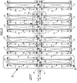
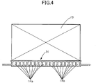
- twelve cooling medium jackets 14 for cooling the battery modules 13 are disposed on a bottom wall of the battery case 12 side by side as two, that is, left and right, lines with their longitudinal direction along the vehicle width direction, and one battery module 13 is disposed on each of the cooling medium jackets 14.
- a cooling medium supply piping 15 and a cooling medium discharge piping 16 are disposed in parallel with each other along the center line of the battery case 12, and an inner end part in the vehicle width direction of the cooling medium jacket 14 is connected to the cooling medium supply piping 15 and the cooling medium discharge piping 16.
- the six pairs of cooling medium jackets 14 have a basically identical structure apart from the details, and the structure of one thereof is explained below as an example.
- the pair of left and right cooling medium jackets 14 are formed as a unit; 18 cooling medium passages are formed in parallel with each other along the vehicle width direction in the interior of a main body part formed from a rectangular metal plate, nine thereof on the front side are cooling medium supply passages 14a, and nine thereof on the rear side are cooling medium discharge passages 14b.
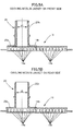
- a plate-shaped mounting portion 14c protrudes in the fore-and-aft direction from a middle part in the vehicle width direction of the cooling medium jackets 14, two mounting holes 14d are formed in each of front and rear sides of the mounting portion 14c (see FIG. 7 ), and one U-shaped cutout 14e is formed in one of the front and rear sides of the mounting portion 14c.
- a plate-shaped mounting portion 14f protrudes in the fore-and-aft direction from an outer end part in the vehicle width direction of the cooling medium jackets 14, and two mounting holes 14g are formed in the mounting portion 14f (see FIG. 6 ).
- a plurality of stud bolts 17 are provided on the bottom wall of the battery case 12 so as to project upward, and fitting these stud bolts 17 into the mounting holes 14d, 14g of the cooling medium jackets 14 and fastening with nuts 18 fixes the cooling medium jackets 14 to the bottom wall of the battery case 12.
- an erroneous assembly-preventing pin 19 projecting upward from the bottom wall of the battery case 12 is fitted into a cutout 14e formed in the mounting portion 14c of the cooling medium jackets 14.
- a nipple-shaped cooling medium inlet 20 includes a plate-shaped blocking portion 20a and a tubular linking portion 20b, and in a state in which the blocking portion 20a is fixed to the peripheral edge of the opening 14h the linking portion 20b is connected to the cooling medium supply piping 15.
- a nipple-shaped cooling medium outlet 21 includes a plate-shaped blocking portion 21a and a tubular linking portion 21b, and in a state in which the blocking portion 21a is fixed to the peripheral edge of the opening 14i the linking portion 21b is connected to the cooling medium discharge piping 16.
- An opening 14j is formed in an upper face of an end part in the vehicle width direction of the cooling medium jacket 14, and the nine cooling medium supply passages 14a and the nine cooling medium discharge passages 14b open in the opening 14j.
- Fixing a cover member 22 with an L-shaped cross section so as to cover the opening 14j of the cooling medium jacket 14 defines a communication chamber 23 between the cooling medium jacket 14 and the cover member 22, and the nine cooling medium supply passages 14a and the nine cooling medium discharge passages 14b are made to communicate with each other via the communication chamber 23.
- three pairs of cooling medium jackets 14 on the upstream side of the cooling medium supply piping 15 (that is, on the front side) and three pairs of cooling medium jackets 14 on the downstream side of the cooling medium supply piping 15 (that is, on the rear side) have slightly different structures.
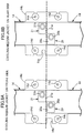
- an internal diameter d1 of the cooling medium inlet 20 of the three pairs of cooling medium jackets 14 on the front side is set to be smaller than an internal diameter d2 of the cooling medium inlet 20 of the three pairs of cooling medium jackets 14 on the rear side.
- an internal diameter d1 of the cooling medium outlet 21 thereof is set to be smaller than an internal diameter d2 of the cooling medium outlet 21 of the three pairs of cooling medium jackets 14 on the rear side.
- the pair of cooling medium jackets 14 can be used with their left and right sides reversed, and in this case the cooling medium inlet 20 and the cooling medium outlet 21 are exchanged and the cooling medium supply passages 14a and the cooling medium discharge passages 14b are exchanged.
- the pair of cooling medium jackets 14 on the front side the pair of cooling medium jacket 14 in the middle in the fore-and-aft direction are flipped horizontally with respect to the other two pairs of cooling medium jackets 14, and among the three pairs of cooling medium jackets 14 on the rear side the pair of cooling medium jacket 14 in the middle in the fore-and-aft direction are flipped horizontally with respect to the other two pairs of cooling medium jackets 14.
- Cooling medium supplied from the cooling medium supply piping 15 branches from the cooling medium inlet 20 of the pair of cooling medium jackets 14 positioned at the frontmost position toward the cooling medium supply passages 14a on the left and right sides, flows outward in the vehicle width direction, makes a U-turn in the communication chambers 23, flows inward in the vehicle width direction in the cooling medium discharge passages 14b on the left and right sides, is combined in the cooling medium outlet 21, and is returned to the cooling medium discharge piping 16.
- the left and right cooling medium jackets 14 are cooled with cooling medium
- the left and right battery modules 13 placed on the upper face thereof carry out heat exchange with the cooling medium jackets 14 and are cooled.
- cooling medium is supplied to the second pair to the sixth pair of cooling medium jackets 14, and the remaining battery modules 13 placed on the upper face thereof are cooled.
- cooling medium is supplied to the cooling medium supply piping 15, which is disposed in the fore-and-aft direction, from the front to the rear, cooling medium is easily supplied to the cooling medium jackets 14 connected to the upstream side of the cooling medium supply piping 15, and it is difficult for cooling medium to be supplied to the cooling medium jackets 14 connected to the downstream side of the cooling medium supply piping 15; in the present embodiment, since the internal diameter d1 of the cooling medium inlets 20 and the cooling medium outlets 21 of the three pairs of cooling medium jackets 14 on the upstream side is set to be small, and the internal diameter d2 of the cooling medium inlets 20 and the cooling medium outlets 21 of the three pairs of cooling medium jackets 14 on the downstream side is set to be large, it is possible by making the amount of cooling medium supplied to the six pairs of cooling medium jackets 14 uniform to evenly cool all of the battery modules 13.
- each cooling medium jacket 14 since the temperature of cooling medium flowing through the interior of each cooling medium jacket 14 is the lowest at the cooling medium inlet 20, gradually increases as a result of heat exchange with the battery module 13 while cooling medium flows through the cooling medium supply passages 14a and the cooling medium discharge passages 14b, and is the highest at the cooling medium outlet 21, there is a possibility that the bottom of the battery module 13 that is in contact with the cooling medium jacket 14 will be cooled unevenly.
- the downstream end of the cooling medium supply passages 14a makes a U-turn in the communication chamber 23 and is connected to the upstream end of the cooling medium discharge passages 14b
- the inner end side in the vehicle width direction of the battery module 13 is cooled with low temperature cooling medium on the upstream side of the cooling medium supply passages 14a and high temperature cooling medium on the downstream side of the cooling medium discharge passages 14b
- the outer end side in the vehicle width direction of the battery module 13 is cooled with an intermediate temperature cooling medium on the downstream side of the cooling medium supply passages 14a and an intermediate temperature cooling medium on the upstream side of the cooling medium discharge passages 14b; as a result, each part in the vehicle width direction of the battery module 13 can be cooled evenly, thereby preventing a difference in temperature from occurring.
- the pair of cooling medium jackets 14 include the cooling medium inlet 20 and the cooling medium outlet 21 in the middle part in the vehicle width direction, and the battery module 13 on the left side and the battery module 13 on the right side are cooled with cooling medium supplied and discharged from the cooling medium inlet 20 and the cooling medium outlet 21, compared with a case in which each cooling medium jacket 14 is provided with the cooling medium inlet 20 and the cooling medium outlet 21, not only can the structure be simplified, but it is also possible to evenly cool the left and right battery modules 13 by making the flow rate of cooling medium supplied to each of the pair of cooling medium jackets 14 uniform.
- FIG. 9 A second embodiment of the present invention is now explained by reference to FIG. 9 .
- downstream end of the cooling medium supply passages 14a of the cooling medium jacket 14 and the upstream end of the cooling medium discharge passages 14b are made to communicate with each other all at once via the communication chamber 23 formed in the interior of the cover member 22, but in the second embodiment the downstream end of the cooling medium supply passages 14a of the cooling medium jacket 14 and the upstream end of the cooling medium discharge passages 14b are made to communicate with each other individually via nine linking passages 14k formed from a U-shaped groove formed in the interior of the cover member 22.
- cooling medium does not form a vortex in the communication chamber 23, thus enabling the cooling medium to make a smooth U-turn.
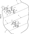
- a third embodiment of the present invention is now explained by reference to FIG. 10 .
- cooling medium jackets 14 formed as separate members are mounted on the bottom wall of the battery case 12 of the battery pack 11, but in the third embodiment the cooling medium jackets 14 are formed integrally with the bottom wall of the battery case 12.
- the embodiments include the twelve cooling medium jackets 14, but there may be any number of cooling medium jackets 14 as long as there are two or more.
- the cutouts 14e there is a large difference in the size of the cutouts 14e between the three pairs of cooling medium jackets 14 on the front side and the three pairs of cooling medium jackets 14 on the rear side, but even when the cutouts 14e have the same size, the function of preventing erroneous assembly is not changed. If the size of the cutouts 14e is different, a worker can differentiate visually between the cooling medium jackets 14 on the front side and the cooling medium jackets 14 on the rear side.
- a cooling medium supply piping and a cooling medium discharge piping are disposed in a fore-and-aft direction in a middle part in a vehicle width direction of a vehicle body.
- a plurality of cooling members extend toward opposite sides in the vehicle width direction from both the pipings.
- a cooling medium passage returns in an outer end part in the vehicle width direction of the cooling member. Therefore, when the vehicle is involved in a side collision, it becomes difficult for both the pipings to be damaged, and cooling medium is prevented from leaking.
- the cooling medium flows by making a U-turn inside the cooling member, thereby enabling positions on outside and inside in the vehicle width direction of a battery to be cooled evenly.
Landscapes
- Engineering & Computer Science (AREA)
- Chemical & Material Sciences (AREA)
- Chemical Kinetics & Catalysis (AREA)
- Electrochemistry (AREA)
- General Chemical & Material Sciences (AREA)
- Manufacturing & Machinery (AREA)
- Mechanical Engineering (AREA)
- Transportation (AREA)
- Power Engineering (AREA)
- Sustainable Energy (AREA)
- Life Sciences & Earth Sciences (AREA)
- Sustainable Development (AREA)
- Combustion & Propulsion (AREA)
- Aviation & Aerospace Engineering (AREA)
- Physics & Mathematics (AREA)
- General Engineering & Computer Science (AREA)
- Thermal Sciences (AREA)
- Cooling, Air Intake And Gas Exhaust, And Fuel Tank Arrangements In Propulsion Units (AREA)
- Secondary Cells (AREA)
- Arrangement Or Mounting Of Propulsion Units For Vehicles (AREA)
- Body Structure For Vehicles (AREA)
- Electric Propulsion And Braking For Vehicles (AREA)
Claims (4)
- Batteriekühlvorrichtung für ein elektrisches Fahrzeug, umfassend:eine Batterie (13), die zum Antrieb des elektrischen Fahrzeugs dient;ein Kühlelement (14), das in seinem Inneren einen Kühlmittelkanal (14a, 14b) aufweist,ein Kühlmittelzuführrohr (15), das dem Kühlelement (14) Kühlmittel zuführt; undein Kühlmittelabführrohr (16), das von dem Kühlelement (14) Kühlmittel abführt,wobei das Kühlmittelzuführrohr (15) und das Kühlmittelabführrohr (16) in einem in Fahrzeugbreitenrichtung eines Fahrzeugkörpers mittleren Teil in einer Vorne-Hinten-Richtung angeordnet sind,eine Mehrzahl von Kühlelementen (14) als das Kühlelement (14) sich in der Fahrzeugbreitenrichtung von dem Kühlmittelzuführrohr (15) und dem Kühlmittelabführrohr (16) zu entgegengesetzten Seiten hin erstrecken, undder Kühlmittelkanal (14a, 14b) in einem in der Fahrzeugbreitenrichtung äußeren Endteil des Kühlelements (14) wendet,dadurch gekennzeichnet, dasszwei der Kühlelemente (14), die sich von dem in der Fahrzeugbreitenrichtung mittleren Teil zu in der Fahrzeugbreitenrichtung entgegengesetzten Seiten hin erstrecken, als eine Einheit ausgebildet sind, unddie zwei Kühlelemente (14) einen gemeinsamen Kühlmitteleinlass (20) undeinen gemeinsamen Kühlmittelauslass (21) aufweisen.
- Die Batteriekühlvorrichtung für ein elektrisches Fahrzeug nach Anspruch 1, wobei in Bezug auf die Mehrzahl von Kühlelementen (14), zwei oder mehr Durchmesser-Typen für den Kühlmitteleinlass (20) vorhanden sind.
- Die Batteriekühlvorrichtung für ein elektrisches Fahrzeug nach Anspruch 2, wobei ein Durchmesser des Kühlmitteleinlasses (20), der mit einer stromaufwärtigen Seite des Kühlmittelzuführrohrs (15) verbunden ist, kleiner ist als ein Durchmesser des Kühlmitteleinlasses (20), der mit einer stromabwärtigen Seite des Kühlmittelzuführrohrs (15) verbunden ist.
- Die Batteriekühlvorrichtung für ein elektrisches Fahrzeug nach Anspruch 3, wobei
das Kühlelement (14) einen an einem Batteriegehäuse (12) befestigen Montageabschnitt (14c) aufweist, und
die Kühlelemente (14), die unterschiedliche Durchmesser für den Kühlmitteleinlass (20) haben, unterschiedliche Formen für den Montageabschnitt (14c) haben.
Applications Claiming Priority (1)
| Application Number | Priority Date | Filing Date | Title |
|---|---|---|---|
| JP2018078426A JP6683756B2 (ja) | 2018-04-16 | 2018-04-16 | 電動車両のバッテリ冷却装置 |
Publications (3)
| Publication Number | Publication Date |
|---|---|
| EP3590748A2 EP3590748A2 (de) | 2020-01-08 |
| EP3590748A3 EP3590748A3 (de) | 2020-02-12 |
| EP3590748B1 true EP3590748B1 (de) | 2021-03-03 |
Family
ID=65995654
Family Applications (1)
| Application Number | Title | Priority Date | Filing Date |
|---|---|---|---|
| EP19165739.4A Active EP3590748B1 (de) | 2018-04-16 | 2019-03-28 | Batteriekühlvorrichtung für elektrofahrzeug |
Country Status (4)
| Country | Link |
|---|---|
| US (1) | US10944137B2 (de) |
| EP (1) | EP3590748B1 (de) |
| JP (1) | JP6683756B2 (de) |
| CN (1) | CN110386032B (de) |
Families Citing this family (13)
| Publication number | Priority date | Publication date | Assignee | Title |
|---|---|---|---|---|
| JP6830979B2 (ja) | 2019-05-16 | 2021-02-17 | 本田技研工業株式会社 | 車両用バッテリユニットの冷却構造 |
| JP7652539B2 (ja) * | 2020-04-16 | 2025-03-27 | 株式会社ブルーエナジー | 蓄電装置 |
| KR102930876B1 (ko) | 2020-04-29 | 2026-02-24 | 주식회사 엘지에너지솔루션 | 배터리 팩, 그것을 포함하는 전자 디바이스, 및 자동차 |
| JP2022012796A (ja) * | 2020-07-02 | 2022-01-17 | 本田技研工業株式会社 | バッテリ装置及び電動車両 |
| US12485981B2 (en) | 2021-03-24 | 2025-12-02 | Polaris Industries Inc. | Electric recreational vehicle |
| JP2023090309A (ja) * | 2021-12-17 | 2023-06-29 | 株式会社ティラド | 組み合わせ部品の誤組防止構造およびその構造を有する熱交換器 |
| JP7154662B1 (ja) | 2022-03-17 | 2022-10-18 | 富士精工株式会社 | バッテリー冷却システム |
| US12123664B2 (en) | 2022-10-28 | 2024-10-22 | Valeo Systemes Thermiques | Tank and tube assembly for a heat exchanger |
| WO2024112704A2 (en) * | 2022-11-21 | 2024-05-30 | Tae Technologies, Inc. | Systems, devices, and methods for battery module cooling |
| FR3146197B1 (fr) * | 2023-02-27 | 2026-01-23 | Valeo Systemes Thermiques | Dispositif de régulation thermique avec collecteur central |
| JP7612737B2 (ja) * | 2023-03-08 | 2025-01-14 | 本田技研工業株式会社 | バッテリパック |
| DE102024113696A1 (de) * | 2024-05-16 | 2025-11-20 | Bayerische Motoren Werke Aktiengesellschaft | Verfahren zum Temperieren von Batteriezellen einer Fahrzeugbatterie mittels einer Temperiereinrichtung sowie Kraftfahrzeug |
| DE102025142499A1 (de) | 2024-11-07 | 2026-05-07 | Isuzu Motors Limited | Batteriepack |
Citations (2)
| Publication number | Priority date | Publication date | Assignee | Title |
|---|---|---|---|---|
| JP2019086183A (ja) * | 2017-11-02 | 2019-06-06 | 昭和電工株式会社 | 伝熱装置 |
| DE102018205962A1 (de) * | 2018-04-19 | 2019-10-24 | Dr. Ing. H.C. F. Porsche Aktiengesellschaft | Traktionsbatterie für ein elektrisch oder teilelektrisch antreibbares Fahrzeug |
Family Cites Families (21)
| Publication number | Priority date | Publication date | Assignee | Title |
|---|---|---|---|---|
| US4407269A (en) * | 1978-07-07 | 1983-10-04 | Sunsearch, Inc. | Solar energy collector system having balanced heat-exchange fluid flow |
| JP4608641B2 (ja) * | 2005-04-27 | 2011-01-12 | 株式会社豊田自動織機 | パワーモジュール用ヒートシンク |
| DE102010032899A1 (de) * | 2010-07-30 | 2012-02-02 | Valeo Klimasysteme Gmbh | Kühlvorrichtung für eine Fahrzeugbatterie sowie Fahrzeugbatteriebaugruppe mit einer solchen Kühlvorrichtung |
| JP5124006B2 (ja) * | 2010-11-16 | 2013-01-23 | 本田技研工業株式会社 | バッテリの冷却構造 |
| JP5533640B2 (ja) * | 2010-12-24 | 2014-06-25 | トヨタ自動車株式会社 | 電池冷却構造 |
| JP2013067335A (ja) * | 2011-09-26 | 2013-04-18 | Fuji Heavy Ind Ltd | 車載バッテリの冷却構造 |
| KR101372096B1 (ko) * | 2011-11-18 | 2014-03-07 | 엘지전자 주식회사 | 열교환기 |
| EP2608309A1 (de) * | 2011-12-21 | 2013-06-26 | Fortu Intellectual Property AG | Batteriemodul mit Batteriemodulgehäuse und Batteriezellen |
| US9647249B2 (en) * | 2012-01-17 | 2017-05-09 | Ford Global Technologies, Llc | Cooling system for vehicle batteries |
| DE102012005871A1 (de) * | 2012-03-23 | 2013-09-26 | Valeo Klimasysteme Gmbh | Kühlvorrichtung für eine Fahrzeugbatterie sowie Fahrzeugbatterie mit Kühlvorrichtung |
| CN202606801U (zh) * | 2012-03-29 | 2012-12-19 | 南通华东油压科技有限公司 | 一种开放式主控液压阀铸件砂芯 |
| CN202871634U (zh) * | 2012-09-10 | 2013-04-10 | 乐清市平兴电子有限公司 | 按钮开关 |
| CN202930463U (zh) * | 2012-10-29 | 2013-05-08 | 天津力神电池股份有限公司 | 18650快速串接标准模块 |
| JP6064730B2 (ja) | 2013-03-26 | 2017-01-25 | 三菱自動車工業株式会社 | 冷却装置 |
| DE102014106954B4 (de) * | 2014-05-16 | 2024-12-24 | Valeo Klimasysteme Gmbh | Vorrichtung zum Heizen und Kühlen eines Batteriepakets sowie Fahrzeugantriebsbatteriebaugruppe |
| US10263301B2 (en) * | 2015-01-09 | 2019-04-16 | Dana Canada Corporation | Counter-flow heat exchanger for battery thermal management applications |
| JP6513427B2 (ja) * | 2015-02-27 | 2019-05-15 | 昭和電工株式会社 | 液冷式冷却装置 |
| DE102015106948A1 (de) * | 2015-05-05 | 2016-11-10 | Dr. Ing. H.C. F. Porsche Aktiengesellschaft | Fahrzeugkomponente |
| DE102015215253A1 (de) * | 2015-08-11 | 2017-02-16 | Bayerische Motoren Werke Aktiengesellschaft | Kühlvorrichtung für Energiespeicher |
| JPWO2017033412A1 (ja) * | 2015-08-27 | 2018-06-14 | 三洋電機株式会社 | バッテリシステム及びバッテリシステムを備える電動車両 |
| CN206124686U (zh) * | 2016-09-23 | 2017-04-26 | 法雷奥汽车空调湖北有限公司 | 一种汽车空调滑动风门的防差错结构 |
-
2018
- 2018-04-16 JP JP2018078426A patent/JP6683756B2/ja active Active
-
2019
- 2019-03-28 EP EP19165739.4A patent/EP3590748B1/de active Active
- 2019-04-04 CN CN201910274420.1A patent/CN110386032B/zh active Active
- 2019-04-15 US US16/384,226 patent/US10944137B2/en active Active
Patent Citations (2)
| Publication number | Priority date | Publication date | Assignee | Title |
|---|---|---|---|---|
| JP2019086183A (ja) * | 2017-11-02 | 2019-06-06 | 昭和電工株式会社 | 伝熱装置 |
| DE102018205962A1 (de) * | 2018-04-19 | 2019-10-24 | Dr. Ing. H.C. F. Porsche Aktiengesellschaft | Traktionsbatterie für ein elektrisch oder teilelektrisch antreibbares Fahrzeug |
Also Published As
| Publication number | Publication date |
|---|---|
| US10944137B2 (en) | 2021-03-09 |
| US20190319319A1 (en) | 2019-10-17 |
| JP2019186149A (ja) | 2019-10-24 |
| EP3590748A2 (de) | 2020-01-08 |
| EP3590748A3 (de) | 2020-02-12 |
| JP6683756B2 (ja) | 2020-04-22 |
| CN110386032B (zh) | 2023-05-23 |
| CN110386032A (zh) | 2019-10-29 |
Similar Documents
| Publication | Publication Date | Title |
|---|---|---|
| EP3590748B1 (de) | Batteriekühlvorrichtung für elektrofahrzeug | |
| KR102740288B1 (ko) | 배터리 팩 하우징 및 이를 포함하는 배터리 팩 | |
| JP6543604B2 (ja) | 車両 | |
| CN110998216B (zh) | 用于电池壳体的调温设备 | |
| CN114383436A (zh) | 具有校准旁路的高性能热交换器 | |
| US20180111500A1 (en) | Vehicle power source system | |
| US10734693B2 (en) | Cell module for electric and hybrid vehicles | |
| WO2020000087A1 (en) | Heat exchanger with internal manifold structure | |
| JP2010503976A (ja) | モジュール化電池装置 | |
| US20250038303A1 (en) | Battery Pack | |
| KR20230126201A (ko) | 배터리 팩 | |
| CN114303276A (zh) | 热交换器 | |
| CN112531260A (zh) | 蓄电池组 | |
| JP7423232B2 (ja) | 車両のバッテリケース用冷却器 | |
| JP7306255B2 (ja) | 熱交換器 | |
| CN119050543A (zh) | 一种电池模组 | |
| US20250158207A1 (en) | Housing | |
| EP4645529A1 (de) | Batteriekühlvorrichtung | |
| KR102878251B1 (ko) | 전기자동차용 배터리 패키지 쿨링 장치 | |
| JP2024046107A (ja) | 電池ケース | |
| KR20250084685A (ko) | 배터리 하우징 | |
| CN216720145U (zh) | 电池包和具有其的车辆 | |
| KR20240086171A (ko) | 고전압 배터리 모듈 | |
| KR20230130902A (ko) | 차량용 냉매 모듈 및 이를 제조하는 제조방법 | |
| CN222655614U (zh) | 箱体、电子设备、动力总成及车辆 |
Legal Events
| Date | Code | Title | Description |
|---|---|---|---|
| PUAI | Public reference made under article 153(3) epc to a published international application that has entered the european phase |
Free format text: ORIGINAL CODE: 0009012 |
|
| STAA | Information on the status of an ep patent application or granted ep patent |
Free format text: STATUS: REQUEST FOR EXAMINATION WAS MADE |
|
| 17P | Request for examination filed |
Effective date: 20190328 |
|
| AK | Designated contracting states |
Kind code of ref document: A2 Designated state(s): AL AT BE BG CH CY CZ DE DK EE ES FI FR GB GR HR HU IE IS IT LI LT LU LV MC MK MT NL NO PL PT RO RS SE SI SK SM TR |
|
| AX | Request for extension of the european patent |
Extension state: BA ME |
|
| PUAL | Search report despatched |
Free format text: ORIGINAL CODE: 0009013 |
|
| AK | Designated contracting states |
Kind code of ref document: A3 Designated state(s): AL AT BE BG CH CY CZ DE DK EE ES FI FR GB GR HR HU IE IS IT LI LT LU LV MC MK MT NL NO PL PT RO RS SE SI SK SM TR |
|
| AX | Request for extension of the european patent |
Extension state: BA ME |
|
| RIC1 | Information provided on ipc code assigned before grant |
Ipc: B60K 1/04 20190101ALI20200109BHEP Ipc: B60K 1/00 20060101AFI20200109BHEP Ipc: H01M 10/625 20140101ALI20200109BHEP Ipc: F28F 3/12 20060101ALI20200109BHEP Ipc: H01M 10/613 20140101ALI20200109BHEP Ipc: H01M 10/617 20140101ALI20200109BHEP |
|
| GRAP | Despatch of communication of intention to grant a patent |
Free format text: ORIGINAL CODE: EPIDOSNIGR1 |
|
| STAA | Information on the status of an ep patent application or granted ep patent |
Free format text: STATUS: GRANT OF PATENT IS INTENDED |
|
| INTG | Intention to grant announced |
Effective date: 20201113 |
|
| GRAS | Grant fee paid |
Free format text: ORIGINAL CODE: EPIDOSNIGR3 |
|
| GRAA | (expected) grant |
Free format text: ORIGINAL CODE: 0009210 |
|
| STAA | Information on the status of an ep patent application or granted ep patent |
Free format text: STATUS: THE PATENT HAS BEEN GRANTED |
|
| AK | Designated contracting states |
Kind code of ref document: B1 Designated state(s): AL AT BE BG CH CY CZ DE DK EE ES FI FR GB GR HR HU IE IS IT LI LT LU LV MC MK MT NL NO PL PT RO RS SE SI SK SM TR |
|
| REG | Reference to a national code |
Ref country code: GB Ref legal event code: FG4D |
|
| REG | Reference to a national code |
Ref country code: CH Ref legal event code: EP Ref country code: AT Ref legal event code: REF Ref document number: 1366826 Country of ref document: AT Kind code of ref document: T Effective date: 20210315 |
|
| REG | Reference to a national code |
Ref country code: DE Ref legal event code: R096 Ref document number: 602019002853 Country of ref document: DE |
|
| REG | Reference to a national code |
Ref country code: IE Ref legal event code: FG4D |
|
| REG | Reference to a national code |
Ref country code: LT Ref legal event code: MG9D |
|
| PG25 | Lapsed in a contracting state [announced via postgrant information from national office to epo] |
Ref country code: NO Free format text: LAPSE BECAUSE OF FAILURE TO SUBMIT A TRANSLATION OF THE DESCRIPTION OR TO PAY THE FEE WITHIN THE PRESCRIBED TIME-LIMIT Effective date: 20210603 Ref country code: LT Free format text: LAPSE BECAUSE OF FAILURE TO SUBMIT A TRANSLATION OF THE DESCRIPTION OR TO PAY THE FEE WITHIN THE PRESCRIBED TIME-LIMIT Effective date: 20210303 Ref country code: GR Free format text: LAPSE BECAUSE OF FAILURE TO SUBMIT A TRANSLATION OF THE DESCRIPTION OR TO PAY THE FEE WITHIN THE PRESCRIBED TIME-LIMIT Effective date: 20210604 Ref country code: FI Free format text: LAPSE BECAUSE OF FAILURE TO SUBMIT A TRANSLATION OF THE DESCRIPTION OR TO PAY THE FEE WITHIN THE PRESCRIBED TIME-LIMIT Effective date: 20210303 Ref country code: HR Free format text: LAPSE BECAUSE OF FAILURE TO SUBMIT A TRANSLATION OF THE DESCRIPTION OR TO PAY THE FEE WITHIN THE PRESCRIBED TIME-LIMIT Effective date: 20210303 Ref country code: BG Free format text: LAPSE BECAUSE OF FAILURE TO SUBMIT A TRANSLATION OF THE DESCRIPTION OR TO PAY THE FEE WITHIN THE PRESCRIBED TIME-LIMIT Effective date: 20210603 |
|
| REG | Reference to a national code |
Ref country code: NL Ref legal event code: MP Effective date: 20210303 |
|
| REG | Reference to a national code |
Ref country code: AT Ref legal event code: MK05 Ref document number: 1366826 Country of ref document: AT Kind code of ref document: T Effective date: 20210303 |
|
| PG25 | Lapsed in a contracting state [announced via postgrant information from national office to epo] |
Ref country code: LV Free format text: LAPSE BECAUSE OF FAILURE TO SUBMIT A TRANSLATION OF THE DESCRIPTION OR TO PAY THE FEE WITHIN THE PRESCRIBED TIME-LIMIT Effective date: 20210303 Ref country code: RS Free format text: LAPSE BECAUSE OF FAILURE TO SUBMIT A TRANSLATION OF THE DESCRIPTION OR TO PAY THE FEE WITHIN THE PRESCRIBED TIME-LIMIT Effective date: 20210303 Ref country code: PL Free format text: LAPSE BECAUSE OF FAILURE TO SUBMIT A TRANSLATION OF THE DESCRIPTION OR TO PAY THE FEE WITHIN THE PRESCRIBED TIME-LIMIT Effective date: 20210303 Ref country code: SE Free format text: LAPSE BECAUSE OF FAILURE TO SUBMIT A TRANSLATION OF THE DESCRIPTION OR TO PAY THE FEE WITHIN THE PRESCRIBED TIME-LIMIT Effective date: 20210303 |
|
| PG25 | Lapsed in a contracting state [announced via postgrant information from national office to epo] |
Ref country code: NL Free format text: LAPSE BECAUSE OF FAILURE TO SUBMIT A TRANSLATION OF THE DESCRIPTION OR TO PAY THE FEE WITHIN THE PRESCRIBED TIME-LIMIT Effective date: 20210303 |
|
| PG25 | Lapsed in a contracting state [announced via postgrant information from national office to epo] |
Ref country code: SM Free format text: LAPSE BECAUSE OF FAILURE TO SUBMIT A TRANSLATION OF THE DESCRIPTION OR TO PAY THE FEE WITHIN THE PRESCRIBED TIME-LIMIT Effective date: 20210303 Ref country code: AT Free format text: LAPSE BECAUSE OF FAILURE TO SUBMIT A TRANSLATION OF THE DESCRIPTION OR TO PAY THE FEE WITHIN THE PRESCRIBED TIME-LIMIT Effective date: 20210303 Ref country code: CZ Free format text: LAPSE BECAUSE OF FAILURE TO SUBMIT A TRANSLATION OF THE DESCRIPTION OR TO PAY THE FEE WITHIN THE PRESCRIBED TIME-LIMIT Effective date: 20210303 Ref country code: EE Free format text: LAPSE BECAUSE OF FAILURE TO SUBMIT A TRANSLATION OF THE DESCRIPTION OR TO PAY THE FEE WITHIN THE PRESCRIBED TIME-LIMIT Effective date: 20210303 |
|
| PG25 | Lapsed in a contracting state [announced via postgrant information from national office to epo] |
Ref country code: IS Free format text: LAPSE BECAUSE OF FAILURE TO SUBMIT A TRANSLATION OF THE DESCRIPTION OR TO PAY THE FEE WITHIN THE PRESCRIBED TIME-LIMIT Effective date: 20210703 Ref country code: RO Free format text: LAPSE BECAUSE OF FAILURE TO SUBMIT A TRANSLATION OF THE DESCRIPTION OR TO PAY THE FEE WITHIN THE PRESCRIBED TIME-LIMIT Effective date: 20210303 Ref country code: PT Free format text: LAPSE BECAUSE OF FAILURE TO SUBMIT A TRANSLATION OF THE DESCRIPTION OR TO PAY THE FEE WITHIN THE PRESCRIBED TIME-LIMIT Effective date: 20210705 Ref country code: SK Free format text: LAPSE BECAUSE OF FAILURE TO SUBMIT A TRANSLATION OF THE DESCRIPTION OR TO PAY THE FEE WITHIN THE PRESCRIBED TIME-LIMIT Effective date: 20210303 |
|
| REG | Reference to a national code |
Ref country code: DE Ref legal event code: R097 Ref document number: 602019002853 Country of ref document: DE |
|
| REG | Reference to a national code |
Ref country code: BE Ref legal event code: MM Effective date: 20210331 |
|
| PLBE | No opposition filed within time limit |
Free format text: ORIGINAL CODE: 0009261 |
|
| STAA | Information on the status of an ep patent application or granted ep patent |
Free format text: STATUS: NO OPPOSITION FILED WITHIN TIME LIMIT |
|
| PG25 | Lapsed in a contracting state [announced via postgrant information from national office to epo] |
Ref country code: FR Free format text: LAPSE BECAUSE OF NON-PAYMENT OF DUE FEES Effective date: 20210503 Ref country code: MC Free format text: LAPSE BECAUSE OF FAILURE TO SUBMIT A TRANSLATION OF THE DESCRIPTION OR TO PAY THE FEE WITHIN THE PRESCRIBED TIME-LIMIT Effective date: 20210303 Ref country code: AL Free format text: LAPSE BECAUSE OF FAILURE TO SUBMIT A TRANSLATION OF THE DESCRIPTION OR TO PAY THE FEE WITHIN THE PRESCRIBED TIME-LIMIT Effective date: 20210303 Ref country code: DK Free format text: LAPSE BECAUSE OF FAILURE TO SUBMIT A TRANSLATION OF THE DESCRIPTION OR TO PAY THE FEE WITHIN THE PRESCRIBED TIME-LIMIT Effective date: 20210303 Ref country code: LU Free format text: LAPSE BECAUSE OF NON-PAYMENT OF DUE FEES Effective date: 20210328 Ref country code: IE Free format text: LAPSE BECAUSE OF NON-PAYMENT OF DUE FEES Effective date: 20210328 Ref country code: ES Free format text: LAPSE BECAUSE OF FAILURE TO SUBMIT A TRANSLATION OF THE DESCRIPTION OR TO PAY THE FEE WITHIN THE PRESCRIBED TIME-LIMIT Effective date: 20210303 |
|
| 26N | No opposition filed |
Effective date: 20211206 |
|
| PG25 | Lapsed in a contracting state [announced via postgrant information from national office to epo] |
Ref country code: SI Free format text: LAPSE BECAUSE OF FAILURE TO SUBMIT A TRANSLATION OF THE DESCRIPTION OR TO PAY THE FEE WITHIN THE PRESCRIBED TIME-LIMIT Effective date: 20210303 |
|
| PG25 | Lapsed in a contracting state [announced via postgrant information from national office to epo] |
Ref country code: IT Free format text: LAPSE BECAUSE OF FAILURE TO SUBMIT A TRANSLATION OF THE DESCRIPTION OR TO PAY THE FEE WITHIN THE PRESCRIBED TIME-LIMIT Effective date: 20210303 |
|
| PG25 | Lapsed in a contracting state [announced via postgrant information from national office to epo] |
Ref country code: IS Free format text: LAPSE BECAUSE OF FAILURE TO SUBMIT A TRANSLATION OF THE DESCRIPTION OR TO PAY THE FEE WITHIN THE PRESCRIBED TIME-LIMIT Effective date: 20210703 |
|
| PG25 | Lapsed in a contracting state [announced via postgrant information from national office to epo] |
Ref country code: BE Free format text: LAPSE BECAUSE OF NON-PAYMENT OF DUE FEES Effective date: 20210331 |
|
| REG | Reference to a national code |
Ref country code: DE Ref legal event code: R084 Ref document number: 602019002853 Country of ref document: DE |
|
| REG | Reference to a national code |
Ref country code: CH Ref legal event code: PL |
|
| PG25 | Lapsed in a contracting state [announced via postgrant information from national office to epo] |
Ref country code: LI Free format text: LAPSE BECAUSE OF NON-PAYMENT OF DUE FEES Effective date: 20220331 Ref country code: CH Free format text: LAPSE BECAUSE OF NON-PAYMENT OF DUE FEES Effective date: 20220331 |
|
| PG25 | Lapsed in a contracting state [announced via postgrant information from national office to epo] |
Ref country code: CY Free format text: LAPSE BECAUSE OF FAILURE TO SUBMIT A TRANSLATION OF THE DESCRIPTION OR TO PAY THE FEE WITHIN THE PRESCRIBED TIME-LIMIT Effective date: 20210303 |
|
| PG25 | Lapsed in a contracting state [announced via postgrant information from national office to epo] |
Ref country code: HU Free format text: LAPSE BECAUSE OF FAILURE TO SUBMIT A TRANSLATION OF THE DESCRIPTION OR TO PAY THE FEE WITHIN THE PRESCRIBED TIME-LIMIT; INVALID AB INITIO Effective date: 20190328 |
|
| GBPC | Gb: european patent ceased through non-payment of renewal fee |
Effective date: 20230328 |
|
| PG25 | Lapsed in a contracting state [announced via postgrant information from national office to epo] |
Ref country code: GB Free format text: LAPSE BECAUSE OF NON-PAYMENT OF DUE FEES Effective date: 20230328 |
|
| PG25 | Lapsed in a contracting state [announced via postgrant information from national office to epo] |
Ref country code: GB Free format text: LAPSE BECAUSE OF NON-PAYMENT OF DUE FEES Effective date: 20230328 |
|
| PG25 | Lapsed in a contracting state [announced via postgrant information from national office to epo] |
Ref country code: MK Free format text: LAPSE BECAUSE OF FAILURE TO SUBMIT A TRANSLATION OF THE DESCRIPTION OR TO PAY THE FEE WITHIN THE PRESCRIBED TIME-LIMIT Effective date: 20210303 |
|
| PG25 | Lapsed in a contracting state [announced via postgrant information from national office to epo] |
Ref country code: TR Free format text: LAPSE BECAUSE OF FAILURE TO SUBMIT A TRANSLATION OF THE DESCRIPTION OR TO PAY THE FEE WITHIN THE PRESCRIBED TIME-LIMIT Effective date: 20210303 |
|
| PG25 | Lapsed in a contracting state [announced via postgrant information from national office to epo] |
Ref country code: MT Free format text: LAPSE BECAUSE OF FAILURE TO SUBMIT A TRANSLATION OF THE DESCRIPTION OR TO PAY THE FEE WITHIN THE PRESCRIBED TIME-LIMIT Effective date: 20210303 |
|
| PGFP | Annual fee paid to national office [announced via postgrant information from national office to epo] |
Ref country code: DE Payment date: 20260219 Year of fee payment: 8 |