EP3590667A1 - Système de nettoyage pour un robot de cuisine utilisé dans la gastronomie, et système de robot de cuisine et cuisine gastronomique ainsi que procédé de nettoyage pour un système de robot de cuisine - Google Patents
Système de nettoyage pour un robot de cuisine utilisé dans la gastronomie, et système de robot de cuisine et cuisine gastronomique ainsi que procédé de nettoyage pour un système de robot de cuisine Download PDFInfo
- Publication number
- EP3590667A1 EP3590667A1 EP18182019.2A EP18182019A EP3590667A1 EP 3590667 A1 EP3590667 A1 EP 3590667A1 EP 18182019 A EP18182019 A EP 18182019A EP 3590667 A1 EP3590667 A1 EP 3590667A1
- Authority
- EP
- European Patent Office
- Prior art keywords
- cleaning
- kitchen
- robot
- cleaning system
- following additional
- Prior art date
- Legal status (The legal status is an assumption and is not a legal conclusion. Google has not performed a legal analysis and makes no representation as to the accuracy of the status listed.)
- Granted
Links
- 238000004140 cleaning Methods 0.000 title claims abstract description 235
- 238000000034 method Methods 0.000 title claims description 9
- 239000007788 liquid Substances 0.000 claims description 45
- 239000003595 mist Substances 0.000 claims description 18
- 238000009413 insulation Methods 0.000 claims description 17
- 238000002360 preparation method Methods 0.000 claims description 10
- 238000007789 sealing Methods 0.000 claims description 8
- 235000013305 food Nutrition 0.000 claims description 2
- 238000010276 construction Methods 0.000 description 8
- 239000000126 substance Substances 0.000 description 6
- 230000033001 locomotion Effects 0.000 description 4
- 230000000694 effects Effects 0.000 description 3
- 238000002955 isolation Methods 0.000 description 3
- 239000007921 spray Substances 0.000 description 3
- 239000004744 fabric Substances 0.000 description 2
- 235000015220 hamburgers Nutrition 0.000 description 2
- 235000013372 meat Nutrition 0.000 description 2
- 238000001556 precipitation Methods 0.000 description 2
- 241000446313 Lamella Species 0.000 description 1
- 230000006978 adaptation Effects 0.000 description 1
- 239000000443 aerosol Substances 0.000 description 1
- 230000000844 anti-bacterial effect Effects 0.000 description 1
- 230000001580 bacterial effect Effects 0.000 description 1
- 230000015572 biosynthetic process Effects 0.000 description 1
- 239000000356 contaminant Substances 0.000 description 1
- 238000011109 contamination Methods 0.000 description 1
- 238000010411 cooking Methods 0.000 description 1
- 230000008878 coupling Effects 0.000 description 1
- 238000010168 coupling process Methods 0.000 description 1
- 238000005859 coupling reaction Methods 0.000 description 1
- 238000007599 discharging Methods 0.000 description 1
- 238000009434 installation Methods 0.000 description 1
- 230000010354 integration Effects 0.000 description 1
- 238000004519 manufacturing process Methods 0.000 description 1
- NJPPVKZQTLUDBO-UHFFFAOYSA-N novaluron Chemical compound C1=C(Cl)C(OC(F)(F)C(OC(F)(F)F)F)=CC=C1NC(=O)NC(=O)C1=C(F)C=CC=C1F NJPPVKZQTLUDBO-UHFFFAOYSA-N 0.000 description 1
- 230000002787 reinforcement Effects 0.000 description 1
- 238000004904 shortening Methods 0.000 description 1
- 239000007787 solid Substances 0.000 description 1
- 238000003860 storage Methods 0.000 description 1
- XLYOFNOQVPJJNP-UHFFFAOYSA-N water Substances O XLYOFNOQVPJJNP-UHFFFAOYSA-N 0.000 description 1
- 230000003313 weakening effect Effects 0.000 description 1
- 238000009736 wetting Methods 0.000 description 1
Images


Classifications
-
- B—PERFORMING OPERATIONS; TRANSPORTING
- B25—HAND TOOLS; PORTABLE POWER-DRIVEN TOOLS; MANIPULATORS
- B25J—MANIPULATORS; CHAMBERS PROVIDED WITH MANIPULATION DEVICES
- B25J19/00—Accessories fitted to manipulators, e.g. for monitoring, for viewing; Safety devices combined with or specially adapted for use in connection with manipulators
- B25J19/0058—Means for cleaning manipulators, e.g. dust removing means
-
- B—PERFORMING OPERATIONS; TRANSPORTING
- B08—CLEANING
- B08B—CLEANING IN GENERAL; PREVENTION OF FOULING IN GENERAL
- B08B15/00—Preventing escape of dirt or fumes from the area where they are produced; Collecting or removing dirt or fumes from that area
- B08B15/02—Preventing escape of dirt or fumes from the area where they are produced; Collecting or removing dirt or fumes from that area using chambers or hoods covering the area
-
- B—PERFORMING OPERATIONS; TRANSPORTING
- B08—CLEANING
- B08B—CLEANING IN GENERAL; PREVENTION OF FOULING IN GENERAL
- B08B17/00—Methods preventing fouling
- B08B17/02—Preventing deposition of fouling or of dust
- B08B17/025—Prevention of fouling with liquids by means of devices for containing or collecting said liquids
-
- B—PERFORMING OPERATIONS; TRANSPORTING
- B08—CLEANING
- B08B—CLEANING IN GENERAL; PREVENTION OF FOULING IN GENERAL
- B08B3/00—Cleaning by methods involving the use or presence of liquid or steam
- B08B3/02—Cleaning by the force of jets or sprays
-
- B—PERFORMING OPERATIONS; TRANSPORTING
- B08—CLEANING
- B08B—CLEANING IN GENERAL; PREVENTION OF FOULING IN GENERAL
- B08B2203/00—Details of cleaning machines or methods involving the use or presence of liquid or steam
- B08B2203/02—Details of machines or methods for cleaning by the force of jets or sprays
- B08B2203/0229—Suction chambers for aspirating the sprayed liquid
-
- B—PERFORMING OPERATIONS; TRANSPORTING
- B08—CLEANING
- B08B—CLEANING IN GENERAL; PREVENTION OF FOULING IN GENERAL
- B08B2203/00—Details of cleaning machines or methods involving the use or presence of liquid or steam
- B08B2203/02—Details of machines or methods for cleaning by the force of jets or sprays
- B08B2203/0264—Splash guards
Definitions
- the invention relates to the field of kitchen robot systems and their cleaning.
- a kitchen robot in the sense of the invention is a system with a kitchen robot which can be moved in a fixed position in the kitchen or by means of a rail system, the kitchen robot having a robot arm which can move in itself and by means of which kitchen tools can be handled.
- Such kitchen robots are not yet very common. However, it is foreseeable that regular use in gastronomy is to be expected, particularly for mechanically simple tasks in the kitchen area. The use of such kitchen robots is particularly useful in the area of system catering with comparatively simple dishes and frequently repeated work steps.
- One example of an activity to be mentioned here is the preparation and turning of burger meat.
- the object of the invention is to provide a cleaning system and a kitchen robot system which allow easier cleaning of kitchen robots in the catering trade.
- this is achieved primarily by means of a cleaning system for a kitchen robot used in the catering trade.
- the cleaning system forms a cleaning room for receiving the kitchen robot at least in sections.
- This cleaning space is limited at least in sections by a flexible wall of the cleaning system, so that the cleaning space is thereby isolated from the surroundings of the kitchen.
- the cleaning system has a delivery system for a cleaning medium, which has at least one discharge nozzle, by means of which the cleaning medium can be introduced into the isolated cleaning room.
- the inventive formation of the cleaning room through a flexible wall has proven to be a particularly quick and inexpensive way to isolate the robot.
- Corresponding walls, which isolate the robot in the manner of a curtain or a covering can be stored in a space-saving manner when not in use, can be handled well by one person alone and are inexpensive to manufacture.
- the cleaning medium is usually a liquid which can dissolve the dirt, in particular by means of a fat-dissolving component, and which, additionally or alternatively, can prevent bacterial growth by means of an antibacterial effect.
- Several cleaning media can also be used simultaneously or in succession if the application system is designed for this.
- the cleaning medium is introduced as intended in the cleaning space formed or closed by the flexible wall in order to be deposited on the robot arm or its parts and / or to detach contaminants from here due to the liquid pressure.
- Two different designs of the flexible wall are preferred, namely on the one hand a construction with a cleaning hose which surrounds the kitchen robot or its robot arm at least in sections in the manner of a covering, and on the other hand a construction with an insulation tarpaulin attached to the walls of a kitchen appliance, other walls hangs down like a curtain from the kitchen or a frame provided for this purpose, and particularly preferably with further walls of a kitchen appliance or the kitchen together limits the isolated cleaning room.
- this cleaning hose surrounds the robot at least in sections.
- the surrounding space forms the cleaning room or part of it.
- the cleaning hose has at least one open end, so that it can be pulled at least over the gripper or the robot arm of the kitchen robot or over the entire kitchen robot and can thus isolate this gripper or robot arm or the entire kitchen robot from an environment.
- the cleaning hose therefore has at least one opening or open side, by means of which it can be pulled over the robot arm.
- the cleaning hose is preferably closed, with the exception of liquid inlets or outlets.
- a hose that is open on both sides, one end of which is permanently attached to the robot can also be advantageous.
- the cleaning hose preferably has an elongated shape corresponding to the longitudinal extent of a robot arm. This form is not important, however.
- a rather sack-like cover body that can surround the robot arm is also understood as a cleaning hose in the sense of the invention. Nevertheless, it is advantageous if the inner volume of the hose is at least roughly adapted to the robot arm to be encased. It is considered advantageous if the volume of the robot arm defined by the outer contour of the robot arm takes up at least 5%, in particular at least 10%, of the maximum volume of the cleaning hose.
- the cleaning hose is preferably made of PVC or another deformable plastic.
- the hose is inherently rigid to a limited extent by structuring its walls with partial reinforcements and / or weakenings, in particular in the manner of a bellows. This makes it difficult for the walls, which are undesirable for cleaning, to be placed directly on surfaces of the robot arm.
- a sealing device is preferably provided at at least one open end.
- This preferably comprises a circumferential sealing surface, which can be formed, for example, pointing inwards or in the direction of the end.
- the sealing surface is preferably deformable or even elastically stretchable and intended to rest on a counter surface of the kitchen robot.
- the above-mentioned tangential extensibility is particularly advantageous, since it allows a comparatively high degree of tightness to be achieved in a simple manner by the fact that the extensible sealing surface can be flexibly applied to surfaces of the robot arm in the manner of an elastic band.
- the cleaning system has a deformable insulation tarpaulin which at least partially forms the flexible wall.
- This insulation tarpaulin is preferably provided for attachment to a wall within the kitchen and, together with walls of the kitchen or the kitchen appliance, forms the cleaning space which is insulated from the environment for the purpose of cleaning the robot.
- walls of the workplace of the robot are thus preferably formed by structures that are present anyway, and the flexible wall, together with these, encloses the cleaning room in which the robot is mounted.
- the wall can hang like a curtain on the floor or in the direction of another kitchen surface or rest with its end on this.
- the insulation tarpaulin is preferably designed for releasable fastening to a rigid wall, in particular by a magnetically acting fastening system. This allows the insulation tarpaulin to be attached quickly in order to create the cleaning space.
- the application system of a cleaning system is intended for introducing cleaning liquid into the cleaning room which is insulated from the surroundings.
- it comprises a tank for stored cleaning liquid, a delivery device such as a pump, and channels that connect the tank and the delivery device to the discharge nozzle.
- the discharge nozzle is directed into the cleaning room, so that the liquid thereby discharged reaches the cleaning room and there meets the surfaces to be cleaned or is deposited thereon.
- the at least one discharge nozzle is integrated in the flexible wall of the cleaning system. This means that the component that also includes the flexible wall that holds at least one nozzle in position. This leads to a quite practical construction of the cleaning system, since the application system or its discharge nozzle is already positioned by the flexible wall. Cleaning can therefore begin immediately after the wall is attached.
- An alternative arrangement of the at least one discharge nozzle which, in the case of several discharge nozzles, can also be combined with the aforementioned design with discharge nozzle in the flexible wall according to the above description, provides that the discharge nozzle is fixed in place on the kitchen robot or in the area of the kitchen robot on a wall , Such a construction is particularly useful if at least parts of the application system and in particular the discharge nozzle are provided for being permanently installed in place.
- the discharge nozzle can be provided on a movable member of the robot arm. This means that the discharge nozzle is in close proximity to the surfaces of the robot arm to be cleaned. On the other hand, this arrangement of the cleaning nozzle also allows it to be used for cleaning surrounding surfaces by moving the robot arm along these surfaces for this purpose while cleaning medium is being discharged.
- the liquid cleaning medium is introduced into the cleaning space via the discharge nozzle mentioned, preferably in the form of a jet, a spray jet or a mist.
- a suitable discharge nozzle should be selected, in particular a single-substance nozzle or a two-substance nozzle.
- the application system can also be designed to introduce a further liquid into the cleaning chamber, which can in particular be a second cleaning medium which is introduced simultaneously, before or after the first cleaning medium.
- the further liquid can also be a rinsing liquid, in particular be water, by means of which the first cleaning medium is removed from the surfaces.
- the discharge of the cleaning medium in the form of a mist is particularly preferred.
- the mist settles reliably on all surfaces that require cleaning and also comes to hard-to-reach surfaces that are difficult or hardly accessible with a spray jet or jet.
- a design of the cleaning system in which the application system has a plurality of dispensing nozzles spaced apart from one another is therefore of particular advantage.
- At least one of the discharge nozzles is designed to generate the mist.
- the at least one further discharge nozzle is arranged or designed such that it can influence the spread of the mist of the first discharge nozzle by discharging gas or mist.
- This further discharge nozzle can thus also be a nozzle for introducing mist.
- it can in particular also be a discharge nozzle, by means of which air or another gas is directed into the cleaning room in order to set the cloud of fog already there in motion.
- a plurality of further nozzles which can generate negative pressure and / or positive pressure can also be provided.
- the movement of the mist in the cleaning room favors precipitation on the surfaces of the kitchen robot.
- the cleaning effect is significantly improved by the movement of the mist.
- the cleaning media or the rinsing liquid introduced into the cleaning room can be removed by opening the cleaning room or the flexible one Wall is removed and then the liquid is absorbed with a rag or the like.
- the cleaning system comprises a suction system for removing liquid and / or liquid residues of the cleaning medium and / or the rinsing liquid.
- a suction system has a suction opening at which a negative pressure is present, by means of which the mist can be sucked out of the cleaning room.
- the cleaning system described comprises the discharge device for the cleaning medium and the flexible surface section, by means of which the cleaning space is closed off from the surroundings. Since it is primarily a matter of cleaning the kitchen robot or its robot arm at the place of use, this cleaning room corresponds to the location of the kitchen robot. However, the cleaning room does not have to be completely surrounded by parts of the preferably at least partly mobile cleaning system. Instead, walls of the workplace of the kitchen robot can be used to produce the insulation mentioned.
- the cleaning system described can in principle be suitable for different robot types.
- this hose can be dimensioned sufficiently to encase both smaller and larger robot arms, forming the cleaning room.
- it is advantageous to adapt the cleaning system to a specific robot type since such an adaptation enables easier handling and because parts of the cleaning system can also be integrated directly into the kitchen robot.
- the invention therefore also relates to a kitchen robot system with a kitchen robot and with a cleaning system of the type described above for use in catering.
- the kitchen robot has at least one robot arm, which has a plurality of links, each of which is connected to one another via joints or guides and is movable relative to one another.
- a robot with a robot arm which is designed at least as a 4-axis robot arm and preferably as a 6-axis robot arm, is suitable as a kitchen robot.
- the cleaning chamber which is at least partially delimited by the flexible wall, in particular in the form of a cleaning hose, is preferably adapted to the shape and size of the robot or robot arm.
- the kitchen robot is designed in particular for a stationary arrangement and is therefore firmly attached to a work surface or in an area in front of the work surface, in particular screwed to a pedestal or base.
- the cleaning system is preferably at least partially designed for occasional attachment to the kitchen robot. This applies in particular to the part comprising the flexible wall, which can be stowed elsewhere when not in use.
- the application system can also be provided as a mobile application system which is installed for the purpose of cleaning the kitchen.
- the discharge nozzle can be permanently installed in the cleaning area in the area of the robot or, in particular, can be provided permanently on the robot arm.
- Such an attachment of the discharge nozzle simplifies, on the one hand, the handling of the cleaning system, since no handling of hose lines or the like is required during commissioning.
- the discharge nozzle depending on the type of arrangement of the discharge nozzle on the robot arm, it allows it to be moved by the given mobility of the robot arm during the discharge of the cleaning medium. This makes it possible not only to apply the cleaning liquid to the robot arm itself, but also to include the surrounding surfaces in a targeted manner.
- the feed line to the discharge nozzle in particular in the form of a hose, is also provided on or in the robot arm in a preferred embodiment.
- a design is particularly advantageous in which the feed line is provided within the robot arm, since this avoids complex geometries to be cleaned in the area of the feed line.
- the fixed installation on the kitchen robot or in the area of the kitchen robot can also be provided with regard to the flexible wall.
- the tube shape mentioned can make it possible, by means of a tube that is variable in length, that this tube remains compressed on the robot in an operating state of the robot and is pulled out for the purpose of cleaning, so that it completely or almost completely surrounds the robot arm.
- a design of the cleaning system with a deformable insulation tarpaulin it is possible to store it when it is not in use in a rolled-up stowage condition similar to a roller blind and to unwind it from here for cleaning purposes.
- the invention also relates to a catering kitchen with at least one preparation station or processing station, at which a kitchen robot system of the type described is provided with a cleaning system.
- the preparation station or processing station can be designed for use either by the kitchen robot or a human or can be used solely by the kitchen robot.
- the invention also relates to the method for cleaning a kitchen robot used in the catering trade with a cleaning system of the type described.
- the method relates to the at least two steps that first the gripper or the robot arm of the kitchen robot or the entire kitchen robot in a cleaning room compared to one Kitchen environment is isolated. After this isolation has taken place, a cleaning medium is introduced into the cleaning space by means of the discharge nozzle and is thus applied to surfaces of the gripper, the robot arm or the kitchen robot.
- the method therefore provides that an isolation space is created which surrounds the robot arm and which at least essentially prevents the subsequently introduced cleaning medium from reaching the remaining kitchen space.
- the isolated cleaning room is created at the location where the robot also works in normal kitchen operations.
- the insulation space is at least partially and in some designs predominantly surrounded by the flexible wall, which, depending on the design, envelop the cleaning space or delimit it together with solid walls of the kitchen. At least cleaning liquid is then introduced into the temporary cleaning space thus created, but preferably not necessarily in a nebulized form.
- the dwell time of the robot, the robot arm or the gripper attached to it in the cleaning room can be short, depending on the design of the process ( ⁇ 10 minutes). This is particularly so useful if a particularly effective cleaning liquid is used or if high pressure can be used to remove dirt quickly.
- embodiments of the method are also possible in which the length of stay is longer, in particular at least 30 minutes. This can be the case in particular if the cleaning liquid is used in a nebulized form, so that it takes longer for sufficient cleaning liquid to be deposited on all soiled areas. It can also be useful to leave the robot arm in the cleaning chamber for several hours under the influence of surrounding fog.
- the 1 and 2 show examples of possible arrangements of a kitchen robot 100 in a catering kitchen, which is provided with a preparation station 120, shown here, for example, as a grill station.
- the kitchen robot 100 in the embodiment of Fig. 1 is arranged behind the grill 122 of the preparation station 120, so that cooperative work with a human colleague is advantageously possible.
- the kitchen robot 100 can be installed as shown on the work surface or on a ceiling above the work surface. An additional linear traversability is also conceivable here.
- the kitchen robot 100 in the embodiment of Fig. 2 is arranged in front of the preparation station 120. This configuration is advantageous if the workstation is used exclusively or largely by the kitchen robot 100.
- the kitchen robots 100 shown have a base in the form of a fastening plate or a base and have a robot arm 102 which can be moved in relation thereto and whose members 104 can be pivoted and rotated about several axes.
- a kitchen tool 108 fastened at the distal end by means of an interchangeable coupling 106 can therefore be moved very flexibly in space and can be used, for example, to turn burger meat.
- the activities performed by the kitchen robot 100 are accompanied by contamination of the robot arm 102. While the kitchen tool 108 can only be uncoupled after use for cleaning purposes and can be put into the dishwasher, the rest of the robot arm is too heavy to be cleaned elsewhere.
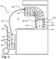
- Fig. 3 shows a first embodiment of a configuration with a cleaning system 20 provided for this purpose.
- the robot arm 102 is shown here during cleaning.
- a cleaning tube 40 has been drawn over the robot arm 102 from the distal end.
- the cleaning hose 40 is shown by way of example as a bellows hose.
- the wall of such a bellows hose is flexible in shape and thus allows simple curvature and shortening when not in use.
- a circumferential and inward-pointing sealing device 44 is provided, which rests on the proximal end of the robot arm 102 on an outside of the kitchen robot 100.
- the cleaning hose 40 is largely closed on the end side, so that the robot arm 102 as a whole is located within the cleaning space 22 closed by the cleaning hose 40.
- a liquid cleaning medium 62 is supplied to the cleaning room 22.
- a delivery system 60 which has a tank 68 and a pump 64 for this purpose.
- the tank and the pump are in the exemplary configuration of the Fig. 3 mounted on a mobile trolley 80.
- the pump 64 is connected via a feed channel 65 designed as a hose to a discharge nozzle 66, which in the present case is designed as a single-substance pressure nozzle, but could also be designed as a two-substance nozzle with a feed for a gas or steam mass flow.
- the discharge nozzle 66 is provided on the end face 46 of the cleaning hose 40 and projects into the cleaning space 22.
- a fine mist 90 of the cleaning medium 62 can be applied to surfaces of the robot arm 102. After the initial or continuous introduction of the fog 90, even hard-to-reach surfaces are gradually reached. After this has been done to a sufficient extent, the cleaning hose 40 can be removed and the cleaning liquid can be absorbed from the surfaces by means of a rag. The cleaning system 20 with the carriage 80 and the cleaning hose 40 can then be used for cleaning another robot or can be cleared to save space.
- the embodiment of the Fig. 4 differs from the previous one only in that the application system 60 is designed as an application system 60 integrated into the robot. This means that the discharge nozzle 66 usually remains installed during the cooking operation. For this purpose, it is provided on one of the limbs 104 of the robot arm 102. The feed channel 65 and the other liquid-carrying components are also permanently installed.
- the preparation of the cleaning process therefore only requires the attachment of the cleaning hose 40, which in this case is closed on the end face 46, and therefore involves little effort.
- the cleaning medium 62 is dispensed via the discharge nozzle 66 in the form of a mist or spray.
- the discharge nozzle 66 can alternatively be designed as a single-substance nozzle or a two-substance nozzle.
- the feed channel 65 in Fig. 4 is designed as a hose attached externally to the robot arm 102, is only provided for a better understanding of the function. In practice, integration of the feed channel into the robot arm is preferred, since this would otherwise make cleaning of the robot arm 102 more difficult.
- the attachment of the discharge nozzle 66 to the robot arm 102 further enables an operating mode in which the robot arm 102 is used for cleaning the rest of the workplace by wetting the surrounding surfaces of the workplace with cleaning medium 62 when the cleaning hose 40 is not attached.
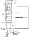
- the embodiment of the Figure 5A and 5B relates to the configuration of the kitchen robot 100 according to that discussed at the beginning Fig. 2 ,
- a cleaning hose 40 is provided, which in a variant of the exemplary embodiment can be provided as a part remaining fixed on the kitchen robot 100 (see Figure 5B ).
- the cleaning hose 40 surrounds the robot arm 102 and has a closed end face 46 at the upper end. At the lower end, the cleaning hose 40 seals with the base of the robot 100, a complete seal not being essential. It is usually sufficient if no large quantities of liquid and in particular no large quantities of atomized liquid emerge here.
- the application system 60 is designed as a permanently installed application system 60. Its discharge nozzles 66 are provided on a distal end of the robot arm 102, the feed channel 65 again being shown as an external hose, but could also be designed as a channel integrated in the robot arm.
- a suction system 70 is also provided, which has a suction opening 76 at the lower end of the cleaning chamber 22, at which a negative pressure is generated by means of a second pump 74 and atomized liquid can thus be transported into a residual liquid tank 78.
- the pump 74 can also be used in reverse pump direction to move the cloud of fog 90 up again.
- Figure 5B shows that in a special embodiment it is also conceivable that the cleaning hose 40 remains on the robot 100.
- the cleaning hose 40 designed as a bellows hose is compressed after removing a closure plate 47 attached to the end of the cleaning hose, so that it does not interfere with the normal operation of the kitchen robot 100.
- Fig. 6 shows an alternative design, the difference to the design of the Figure 5A . 5B this means that discharge nozzles 66 are attached to both the lower proximal end and the upper distal end of the robot arm 102, which in this way allow the mist 90 to be distributed even better throughout the entire cleaning space 22.
- alternating discharge of the cleaning medium in the form of a fog from the lower discharge nozzles 66 and the upper discharge nozzles 66 can also cause a movement of the cloud of fog 90, by means of which precipitation occurs particularly quickly on all surfaces to be cleaned.
- a carriage 80 which comprises the liquid cleaning medium 62 in a tank 68 and an associated pump 64.
- a rinsing liquid 63 is provided in a separate tank 69.
- the cleaning medium 62 and the rinsing liquid 63 can be conveyed to separate discharge nozzles 66, 67 through two feed channels 65 in the form of a hose.
- the discharge nozzles 66, 67 are not provided in a cleaning hose, but instead a flexible insulation tarpaulin 50, that is to say a deformable surface in the manner of a curtain, in the present case a lamella curtain.
- the insulation tarpaulin 50 closes off the grill area of the work station at the front, while the area on the other sides is delimited by walls 2, 3, 4 of the kitchen or the work station. This creates a cleaning room 22, which is closed to the kitchen environment 24.
- the insulation tarpaulin is attached to an extractor hood of the workplace by a magnetically acting fastening system 52 in the form of a magnetic strip.
- the insulation tarpaulin 50 hangs freely on the workplace. Since a special tightness is not important, there is no need for further fastening.
- cleaning medium mist 90 is discharged through the discharge nozzle 66 into the essentially insulated cleaning space 22.
- rinsing is then carried out by rinsing liquid 63, which is sprayed in through the discharge nozzle 67.
- the rinsing liquid removes the cleaning medium from the surfaces of the robot arm 102, which can also be moved for this purpose.
- the rinsing liquid can drain through a drain 124 in the work surface.
- the embodiment of the Fig. 8 differs from that of Fig. 7 in that according to the design of the Fig. 4 the application system 60 is provided as a permanently installed system.
- the discharge nozzle 66 is in turn provided on a link 104 of the robot arm 102.
Priority Applications (1)
| Application Number | Priority Date | Filing Date | Title |
|---|---|---|---|
| EP18182019.2A EP3590667B1 (fr) | 2018-07-05 | 2018-07-05 | Cuisine gastronomique avec robot cuisinier et système de nettoyage de ce robot ainsi que procédé de nettoyage de ce robot |
Applications Claiming Priority (1)
| Application Number | Priority Date | Filing Date | Title |
|---|---|---|---|
| EP18182019.2A EP3590667B1 (fr) | 2018-07-05 | 2018-07-05 | Cuisine gastronomique avec robot cuisinier et système de nettoyage de ce robot ainsi que procédé de nettoyage de ce robot |
Publications (2)
| Publication Number | Publication Date |
|---|---|
| EP3590667A1 true EP3590667A1 (fr) | 2020-01-08 |
| EP3590667B1 EP3590667B1 (fr) | 2023-04-19 |
Family
ID=62874696
Family Applications (1)
| Application Number | Title | Priority Date | Filing Date |
|---|---|---|---|
| EP18182019.2A Active EP3590667B1 (fr) | 2018-07-05 | 2018-07-05 | Cuisine gastronomique avec robot cuisinier et système de nettoyage de ce robot ainsi que procédé de nettoyage de ce robot |
Country Status (1)
| Country | Link |
|---|---|
| EP (1) | EP3590667B1 (fr) |
Cited By (3)
| Publication number | Priority date | Publication date | Assignee | Title |
|---|---|---|---|---|
| CN113143106A (zh) * | 2021-01-29 | 2021-07-23 | 上海优魅贸易有限公司 | 一种清洗柜台的设备 |
| US20220234155A1 (en) * | 2021-01-27 | 2022-07-28 | Festo Se & Co. Kg | Machining system for workpiece machining |
| CN114871227A (zh) * | 2022-06-22 | 2022-08-09 | 浙江炊大王炊具有限公司 | 一种压铸锅体自动擦锅机 |
Citations (8)
| Publication number | Priority date | Publication date | Assignee | Title |
|---|---|---|---|---|
| JPH0163483U (fr) * | 1987-10-16 | 1989-04-24 | ||
| DE4129778A1 (de) * | 1991-09-07 | 1992-07-09 | Daimler Benz Ag | Einrichtung zum selbsttaetigen und emissionsarmen reinigen von maschinengefuehrten spruehorganen |
| JP2005098662A (ja) * | 2003-09-22 | 2005-04-14 | Big Denki:Kk | 壁掛け型エアコンの洗浄カバー |
| US20050193901A1 (en) * | 2004-02-18 | 2005-09-08 | Buehler David B. | Food preparation system |
| EP2542388A1 (fr) * | 2010-03-01 | 2013-01-09 | Abb As | Robot mobile pour un environnement extérieur agressif et corrosif |
| EP2929989A1 (fr) * | 2012-12-05 | 2015-10-14 | Kawasaki Jukogyo Kabushiki Kaisha | Structure d'étanchéité d'articulation de robot |
| US20170188744A1 (en) * | 2015-12-31 | 2017-07-06 | Wu Ge | Cooking robot |
| WO2017220105A1 (fr) * | 2016-06-20 | 2017-12-28 | Abb Schweiz Ag | Appareil, système et procédé de nettoyage d'un objet allongé |
-
2018
- 2018-07-05 EP EP18182019.2A patent/EP3590667B1/fr active Active
Patent Citations (8)
| Publication number | Priority date | Publication date | Assignee | Title |
|---|---|---|---|---|
| JPH0163483U (fr) * | 1987-10-16 | 1989-04-24 | ||
| DE4129778A1 (de) * | 1991-09-07 | 1992-07-09 | Daimler Benz Ag | Einrichtung zum selbsttaetigen und emissionsarmen reinigen von maschinengefuehrten spruehorganen |
| JP2005098662A (ja) * | 2003-09-22 | 2005-04-14 | Big Denki:Kk | 壁掛け型エアコンの洗浄カバー |
| US20050193901A1 (en) * | 2004-02-18 | 2005-09-08 | Buehler David B. | Food preparation system |
| EP2542388A1 (fr) * | 2010-03-01 | 2013-01-09 | Abb As | Robot mobile pour un environnement extérieur agressif et corrosif |
| EP2929989A1 (fr) * | 2012-12-05 | 2015-10-14 | Kawasaki Jukogyo Kabushiki Kaisha | Structure d'étanchéité d'articulation de robot |
| US20170188744A1 (en) * | 2015-12-31 | 2017-07-06 | Wu Ge | Cooking robot |
| WO2017220105A1 (fr) * | 2016-06-20 | 2017-12-28 | Abb Schweiz Ag | Appareil, système et procédé de nettoyage d'un objet allongé |
Non-Patent Citations (1)
| Title |
|---|
| NATIONAL AERONAUTICS AND SPACE ADMINISTRATION, MARSHALL SPACE FLIGHT CENTER: "PORTABLE WATER-SAVING SHOWER FOR EMERGENCIES", NTIS TECH NOTES, US DEPARTMENT OF COMMERCE. SPRINGFIELD, VA, US, 1 March 1992 (1992-03-01), pages 173, XP000291027, ISSN: 0889-8464 * |
Cited By (3)
| Publication number | Priority date | Publication date | Assignee | Title |
|---|---|---|---|---|
| US20220234155A1 (en) * | 2021-01-27 | 2022-07-28 | Festo Se & Co. Kg | Machining system for workpiece machining |
| CN113143106A (zh) * | 2021-01-29 | 2021-07-23 | 上海优魅贸易有限公司 | 一种清洗柜台的设备 |
| CN114871227A (zh) * | 2022-06-22 | 2022-08-09 | 浙江炊大王炊具有限公司 | 一种压铸锅体自动擦锅机 |
Also Published As
| Publication number | Publication date |
|---|---|
| EP3590667B1 (fr) | 2023-04-19 |
Similar Documents
| Publication | Publication Date | Title |
|---|---|---|
| EP3590667B1 (fr) | Cuisine gastronomique avec robot cuisinier et système de nettoyage de ce robot ainsi que procédé de nettoyage de ce robot | |
| DE102016012488B4 (de) | Reinigungs-, Desinfektions- und Trocknungs-Anlage | |
| WO2009056424A1 (fr) | Dispositif de nettoyage pour nettoyer des pistolets pulvérisateurs | |
| WO1982000783A1 (fr) | Procede de travail et dispositif permettant d'executer ce procede, destine au nettoyage d'ustensiles | |
| DE1806634A1 (de) | Spritz- und Spruehvorrichtung und portalartiges Wasch- oder Spritzgestell | |
| DE2849099A1 (de) | Fussbodenreinigungsvorrichtung | |
| EP2220987B1 (fr) | Buse d'extraction par vaporisation destinée au nettoyage d'une surface, notamment à la décontamination de la surface | |
| EP0433589A2 (fr) | Installation de poudrage électrostatique | |
| DE4033321C2 (de) | Wärmetauscher eines Kraftfahrzeuges | |
| WO2023227726A1 (fr) | Tête de nettoyage à la vapeur | |
| CH684390A5 (de) | Reinigungsgerät. | |
| DE19546756C2 (de) | Hochdruckreinigungsvorrichtung | |
| DE102007063162B3 (de) | Modulartig zusammengesetzte Beschichtungszelle | |
| DE3626997A1 (de) | Vorrichtung zum verspruehen duennfluessiger medien | |
| DE102018121708A1 (de) | Reinigungsvorrichtung und Verfahren zum Reinigen eines im Tauchverfahren beschichteten Körpers | |
| DE102008027910A1 (de) | Vorrichtung zum Reinigen von Lackier- und/oder Klebepistolen | |
| DE102019124013B3 (de) | Reinigungsvorrichtung für Rohre, Schläuche oder dergleichen | |
| DE202012008555U1 (de) | Reinigungsvorrichtung zur Reinigung von Spritzpistolen | |
| DE7240741U (de) | Spritzeinrichtung, wie Spritzpistolen und dergleichen mit Loslaß-Abschaltung | |
| EP0341389B1 (fr) | Procédé et installation pour nettoyer les vitres des carrosseries neuves d'automobiles | |
| DE3712474C2 (fr) | ||
| DE4407956A1 (de) | Sandstrahlkasten zur Oberflächenbehandlung von vorzugsweise flachen Materialoberflächen | |
| AT524075B1 (de) | Rohrposthülse zum Desinfizieren eines Rohrleitungssystems einer Rohrpostanlage | |
| WO1997021378A1 (fr) | Dispositif de nettoyage a haute pression | |
| DE2121500A1 (de) | Verfahren und Vorrichtung zur Reinigung der Oberfläche von Festkörpern mit Flüssigkeiten |
Legal Events
| Date | Code | Title | Description |
|---|---|---|---|
| PUAI | Public reference made under article 153(3) epc to a published international application that has entered the european phase |
Free format text: ORIGINAL CODE: 0009012 |
|
| STAA | Information on the status of an ep patent application or granted ep patent |
Free format text: STATUS: THE APPLICATION HAS BEEN PUBLISHED |
|
| AK | Designated contracting states |
Kind code of ref document: A1 Designated state(s): AL AT BE BG CH CY CZ DE DK EE ES FI FR GB GR HR HU IE IS IT LI LT LU LV MC MK MT NL NO PL PT RO RS SE SI SK SM TR |
|
| AX | Request for extension of the european patent |
Extension state: BA ME |
|
| STAA | Information on the status of an ep patent application or granted ep patent |
Free format text: STATUS: REQUEST FOR EXAMINATION WAS MADE |
|
| 17P | Request for examination filed |
Effective date: 20200213 |
|
| RBV | Designated contracting states (corrected) |
Designated state(s): AL AT BE BG CH CY CZ DE DK EE ES FI FR GB GR HR HU IE IS IT LI LT LU LV MC MK MT NL NO PL PT RO RS SE SI SK SM TR |
|
| RIC1 | Information provided on ipc code assigned before grant |
Ipc: B08B 17/02 20060101ALI20220916BHEP Ipc: A47J 27/00 20060101ALI20220916BHEP Ipc: B08B 15/02 20060101ALI20220916BHEP Ipc: B08B 3/02 20060101ALI20220916BHEP Ipc: B25J 19/00 20060101AFI20220916BHEP |
|
| GRAP | Despatch of communication of intention to grant a patent |
Free format text: ORIGINAL CODE: EPIDOSNIGR1 |
|
| STAA | Information on the status of an ep patent application or granted ep patent |
Free format text: STATUS: GRANT OF PATENT IS INTENDED |
|
| INTG | Intention to grant announced |
Effective date: 20221104 |
|
| GRAS | Grant fee paid |
Free format text: ORIGINAL CODE: EPIDOSNIGR3 |
|
| GRAA | (expected) grant |
Free format text: ORIGINAL CODE: 0009210 |
|
| STAA | Information on the status of an ep patent application or granted ep patent |
Free format text: STATUS: THE PATENT HAS BEEN GRANTED |
|
| AK | Designated contracting states |
Kind code of ref document: B1 Designated state(s): AL AT BE BG CH CY CZ DE DK EE ES FI FR GB GR HR HU IE IS IT LI LT LU LV MC MK MT NL NO PL PT RO RS SE SI SK SM TR |
|
| REG | Reference to a national code |
Ref country code: GB Ref legal event code: FG4D Free format text: NOT ENGLISH |
|
| REG | Reference to a national code |
Ref country code: CH Ref legal event code: EP |
|
| REG | Reference to a national code |
Ref country code: DE Ref legal event code: R096 Ref document number: 502018011976 Country of ref document: DE |
|
| REG | Reference to a national code |
Ref country code: IE Ref legal event code: FG4D Free format text: LANGUAGE OF EP DOCUMENT: GERMAN |
|
| REG | Reference to a national code |
Ref country code: AT Ref legal event code: REF Ref document number: 1560845 Country of ref document: AT Kind code of ref document: T Effective date: 20230515 |
|
| P01 | Opt-out of the competence of the unified patent court (upc) registered |
Effective date: 20230502 |
|
| REG | Reference to a national code |
Ref country code: LT Ref legal event code: MG9D |
|
| REG | Reference to a national code |
Ref country code: NL Ref legal event code: MP Effective date: 20230419 |
|
| PG25 | Lapsed in a contracting state [announced via postgrant information from national office to epo] |
Ref country code: NL Free format text: LAPSE BECAUSE OF FAILURE TO SUBMIT A TRANSLATION OF THE DESCRIPTION OR TO PAY THE FEE WITHIN THE PRESCRIBED TIME-LIMIT Effective date: 20230419 |
|
| PG25 | Lapsed in a contracting state [announced via postgrant information from national office to epo] |
Ref country code: SE Free format text: LAPSE BECAUSE OF FAILURE TO SUBMIT A TRANSLATION OF THE DESCRIPTION OR TO PAY THE FEE WITHIN THE PRESCRIBED TIME-LIMIT Effective date: 20230419 Ref country code: PT Free format text: LAPSE BECAUSE OF FAILURE TO SUBMIT A TRANSLATION OF THE DESCRIPTION OR TO PAY THE FEE WITHIN THE PRESCRIBED TIME-LIMIT Effective date: 20230821 Ref country code: NO Free format text: LAPSE BECAUSE OF FAILURE TO SUBMIT A TRANSLATION OF THE DESCRIPTION OR TO PAY THE FEE WITHIN THE PRESCRIBED TIME-LIMIT Effective date: 20230719 Ref country code: ES Free format text: LAPSE BECAUSE OF FAILURE TO SUBMIT A TRANSLATION OF THE DESCRIPTION OR TO PAY THE FEE WITHIN THE PRESCRIBED TIME-LIMIT Effective date: 20230419 |
|
| PGFP | Annual fee paid to national office [announced via postgrant information from national office to epo] |
Ref country code: GB Payment date: 20230724 Year of fee payment: 6 Ref country code: CH Payment date: 20230801 Year of fee payment: 6 Ref country code: AT Payment date: 20230718 Year of fee payment: 6 |
|
| PG25 | Lapsed in a contracting state [announced via postgrant information from national office to epo] |
Ref country code: RS Free format text: LAPSE BECAUSE OF FAILURE TO SUBMIT A TRANSLATION OF THE DESCRIPTION OR TO PAY THE FEE WITHIN THE PRESCRIBED TIME-LIMIT Effective date: 20230419 Ref country code: PL Free format text: LAPSE BECAUSE OF FAILURE TO SUBMIT A TRANSLATION OF THE DESCRIPTION OR TO PAY THE FEE WITHIN THE PRESCRIBED TIME-LIMIT Effective date: 20230419 Ref country code: LV Free format text: LAPSE BECAUSE OF FAILURE TO SUBMIT A TRANSLATION OF THE DESCRIPTION OR TO PAY THE FEE WITHIN THE PRESCRIBED TIME-LIMIT Effective date: 20230419 Ref country code: LT Free format text: LAPSE BECAUSE OF FAILURE TO SUBMIT A TRANSLATION OF THE DESCRIPTION OR TO PAY THE FEE WITHIN THE PRESCRIBED TIME-LIMIT Effective date: 20230419 Ref country code: IS Free format text: LAPSE BECAUSE OF FAILURE TO SUBMIT A TRANSLATION OF THE DESCRIPTION OR TO PAY THE FEE WITHIN THE PRESCRIBED TIME-LIMIT Effective date: 20230819 Ref country code: HR Free format text: LAPSE BECAUSE OF FAILURE TO SUBMIT A TRANSLATION OF THE DESCRIPTION OR TO PAY THE FEE WITHIN THE PRESCRIBED TIME-LIMIT Effective date: 20230419 Ref country code: GR Free format text: LAPSE BECAUSE OF FAILURE TO SUBMIT A TRANSLATION OF THE DESCRIPTION OR TO PAY THE FEE WITHIN THE PRESCRIBED TIME-LIMIT Effective date: 20230720 Ref country code: AL Free format text: LAPSE BECAUSE OF FAILURE TO SUBMIT A TRANSLATION OF THE DESCRIPTION OR TO PAY THE FEE WITHIN THE PRESCRIBED TIME-LIMIT Effective date: 20230419 |
|
| PGFP | Annual fee paid to national office [announced via postgrant information from national office to epo] |
Ref country code: FR Payment date: 20230724 Year of fee payment: 6 Ref country code: DE Payment date: 20230720 Year of fee payment: 6 |
|
| PG25 | Lapsed in a contracting state [announced via postgrant information from national office to epo] |
Ref country code: FI Free format text: LAPSE BECAUSE OF FAILURE TO SUBMIT A TRANSLATION OF THE DESCRIPTION OR TO PAY THE FEE WITHIN THE PRESCRIBED TIME-LIMIT Effective date: 20230419 |
|
| PG25 | Lapsed in a contracting state [announced via postgrant information from national office to epo] |
Ref country code: SK Free format text: LAPSE BECAUSE OF FAILURE TO SUBMIT A TRANSLATION OF THE DESCRIPTION OR TO PAY THE FEE WITHIN THE PRESCRIBED TIME-LIMIT Effective date: 20230419 |
|
| REG | Reference to a national code |
Ref country code: DE Ref legal event code: R097 Ref document number: 502018011976 Country of ref document: DE |
|
| PG25 | Lapsed in a contracting state [announced via postgrant information from national office to epo] |
Ref country code: SM Free format text: LAPSE BECAUSE OF FAILURE TO SUBMIT A TRANSLATION OF THE DESCRIPTION OR TO PAY THE FEE WITHIN THE PRESCRIBED TIME-LIMIT Effective date: 20230419 Ref country code: SK Free format text: LAPSE BECAUSE OF FAILURE TO SUBMIT A TRANSLATION OF THE DESCRIPTION OR TO PAY THE FEE WITHIN THE PRESCRIBED TIME-LIMIT Effective date: 20230419 Ref country code: RO Free format text: LAPSE BECAUSE OF FAILURE TO SUBMIT A TRANSLATION OF THE DESCRIPTION OR TO PAY THE FEE WITHIN THE PRESCRIBED TIME-LIMIT Effective date: 20230419 Ref country code: EE Free format text: LAPSE BECAUSE OF FAILURE TO SUBMIT A TRANSLATION OF THE DESCRIPTION OR TO PAY THE FEE WITHIN THE PRESCRIBED TIME-LIMIT Effective date: 20230419 Ref country code: DK Free format text: LAPSE BECAUSE OF FAILURE TO SUBMIT A TRANSLATION OF THE DESCRIPTION OR TO PAY THE FEE WITHIN THE PRESCRIBED TIME-LIMIT Effective date: 20230419 Ref country code: CZ Free format text: LAPSE BECAUSE OF FAILURE TO SUBMIT A TRANSLATION OF THE DESCRIPTION OR TO PAY THE FEE WITHIN THE PRESCRIBED TIME-LIMIT Effective date: 20230419 |
|
| PLBE | No opposition filed within time limit |
Free format text: ORIGINAL CODE: 0009261 |
|
| STAA | Information on the status of an ep patent application or granted ep patent |
Free format text: STATUS: NO OPPOSITION FILED WITHIN TIME LIMIT |
|
| PG25 | Lapsed in a contracting state [announced via postgrant information from national office to epo] |
Ref country code: MC Free format text: LAPSE BECAUSE OF FAILURE TO SUBMIT A TRANSLATION OF THE DESCRIPTION OR TO PAY THE FEE WITHIN THE PRESCRIBED TIME-LIMIT Effective date: 20230419 |
|
| PG25 | Lapsed in a contracting state [announced via postgrant information from national office to epo] |
Ref country code: MC Free format text: LAPSE BECAUSE OF FAILURE TO SUBMIT A TRANSLATION OF THE DESCRIPTION OR TO PAY THE FEE WITHIN THE PRESCRIBED TIME-LIMIT Effective date: 20230419 |
|
| REG | Reference to a national code |
Ref country code: BE Ref legal event code: MM Effective date: 20230731 |
|
| PG25 | Lapsed in a contracting state [announced via postgrant information from national office to epo] |
Ref country code: LU Free format text: LAPSE BECAUSE OF NON-PAYMENT OF DUE FEES Effective date: 20230705 |
|
| 26N | No opposition filed |
Effective date: 20240122 |
|
| PG25 | Lapsed in a contracting state [announced via postgrant information from national office to epo] |
Ref country code: LU Free format text: LAPSE BECAUSE OF NON-PAYMENT OF DUE FEES Effective date: 20230705 |
|
| PG25 | Lapsed in a contracting state [announced via postgrant information from national office to epo] |
Ref country code: SI Free format text: LAPSE BECAUSE OF FAILURE TO SUBMIT A TRANSLATION OF THE DESCRIPTION OR TO PAY THE FEE WITHIN THE PRESCRIBED TIME-LIMIT Effective date: 20230419 |