EP3590432B1 - Röntgentomografievorrichtung und röntgentomografieverfahren - Google Patents
Röntgentomografievorrichtung und röntgentomografieverfahren Download PDFInfo
- Publication number
- EP3590432B1 EP3590432B1 EP18761564.6A EP18761564A EP3590432B1 EP 3590432 B1 EP3590432 B1 EP 3590432B1 EP 18761564 A EP18761564 A EP 18761564A EP 3590432 B1 EP3590432 B1 EP 3590432B1
- Authority
- EP
- European Patent Office
- Prior art keywords
- ray
- interest
- tomographic layer
- loi
- tomographic
- Prior art date
- Legal status (The legal status is an assumption and is not a legal conclusion. Google has not performed a legal analysis and makes no representation as to the accuracy of the status listed.)
- Active
Links
Images


Classifications
-
- A—HUMAN NECESSITIES
- A61—MEDICAL OR VETERINARY SCIENCE; HYGIENE
- A61B—DIAGNOSIS; SURGERY; IDENTIFICATION
- A61B6/00—Apparatus or devices for radiation diagnosis; Apparatus or devices for radiation diagnosis combined with radiation therapy equipment
- A61B6/50—Apparatus or devices for radiation diagnosis; Apparatus or devices for radiation diagnosis combined with radiation therapy equipment specially adapted for specific body parts; specially adapted for specific clinical applications
- A61B6/51—Apparatus or devices for radiation diagnosis; Apparatus or devices for radiation diagnosis combined with radiation therapy equipment specially adapted for specific body parts; specially adapted for specific clinical applications for dentistry
-
- A—HUMAN NECESSITIES
- A61—MEDICAL OR VETERINARY SCIENCE; HYGIENE
- A61B—DIAGNOSIS; SURGERY; IDENTIFICATION
- A61B6/00—Apparatus or devices for radiation diagnosis; Apparatus or devices for radiation diagnosis combined with radiation therapy equipment
- A61B6/44—Constructional features of apparatus for radiation diagnosis
- A61B6/4429—Constructional features of apparatus for radiation diagnosis related to the mounting of source units and detector units
- A61B6/4435—Constructional features of apparatus for radiation diagnosis related to the mounting of source units and detector units the source unit and the detector unit being coupled by a rigid structure
-
- A—HUMAN NECESSITIES
- A61—MEDICAL OR VETERINARY SCIENCE; HYGIENE
- A61B—DIAGNOSIS; SURGERY; IDENTIFICATION
- A61B6/00—Apparatus or devices for radiation diagnosis; Apparatus or devices for radiation diagnosis combined with radiation therapy equipment
- A61B6/02—Arrangements for diagnosis sequentially in different planes; Stereoscopic radiation diagnosis
- A61B6/025—Tomosynthesis
-
- A—HUMAN NECESSITIES
- A61—MEDICAL OR VETERINARY SCIENCE; HYGIENE
- A61B—DIAGNOSIS; SURGERY; IDENTIFICATION
- A61B6/00—Apparatus or devices for radiation diagnosis; Apparatus or devices for radiation diagnosis combined with radiation therapy equipment
- A61B6/02—Arrangements for diagnosis sequentially in different planes; Stereoscopic radiation diagnosis
- A61B6/03—Computed tomography [CT]
- A61B6/032—Transmission computed tomography [CT]
- A61B6/035—Mechanical aspects of CT
-
- A—HUMAN NECESSITIES
- A61—MEDICAL OR VETERINARY SCIENCE; HYGIENE
- A61B—DIAGNOSIS; SURGERY; IDENTIFICATION
- A61B6/00—Apparatus or devices for radiation diagnosis; Apparatus or devices for radiation diagnosis combined with radiation therapy equipment
- A61B6/46—Arrangements for interfacing with the operator or the patient
- A61B6/467—Arrangements for interfacing with the operator or the patient characterised by special input means
- A61B6/469—Arrangements for interfacing with the operator or the patient characterised by special input means for selecting a region of interest [ROI]
-
- A—HUMAN NECESSITIES
- A61—MEDICAL OR VETERINARY SCIENCE; HYGIENE
- A61B—DIAGNOSIS; SURGERY; IDENTIFICATION
- A61B6/00—Apparatus or devices for radiation diagnosis; Apparatus or devices for radiation diagnosis combined with radiation therapy equipment
- A61B6/54—Control of apparatus or devices for radiation diagnosis
- A61B6/542—Control of apparatus or devices for radiation diagnosis involving control of exposure
-
- A—HUMAN NECESSITIES
- A61—MEDICAL OR VETERINARY SCIENCE; HYGIENE
- A61B—DIAGNOSIS; SURGERY; IDENTIFICATION
- A61B6/00—Apparatus or devices for radiation diagnosis; Apparatus or devices for radiation diagnosis combined with radiation therapy equipment
- A61B6/02—Arrangements for diagnosis sequentially in different planes; Stereoscopic radiation diagnosis
- A61B6/03—Computed tomography [CT]
- A61B6/032—Transmission computed tomography [CT]
Definitions
- the present invention relates to a technique of performing X-ray tomography to acquire an X-ray tomographic image.
- An X-ray CT (computed tomography) imaging apparatus that performs tomographic imaging on any site of a human body is widely known in the field of medical X-ray diagnosis.
- image information an X-ray projection image or a transmission image
- the obtained image information is subjected to image processing to generate the X-ray tomographic image illustrating a tomographic plane obtained by cutting any site such as a head and a body.
- Patent Document 1 discloses a technique of performing CT imaging by reducing an influence of a high X-ray absorption site existing in the subject using a control model based on high X-ray absorption site information existing in the subject. Specifically, at least one of an increase in X-ray output and a decrease in turning speed is performed at timing at which an X-ray cone beam reaches the high X-ray absorption site (for example, a cervical spine). In Patent Document 1, a clear X-ray tomographic image is acquired by reducing the influence of the high X-ray absorption site.
- Patent Document 1 Japanese Patent Application Laid-Open No. 2006-288726
- Document US2010067650 A1 may be considered to disclose an X-ray tomography apparatus comprising: an X-ray generator that emits an X-ray beam; an X-ray detector that detects said X-ray beam emitted from said X-ray generator; a support that supports said X-ray generator and said X-ray detector; a tomographic layer-of-interest setting unit that sets a position of a tomographic area of interest; a turning drive unit that relatively turns said X-ray generator and said X-ray detector around at least a turning center axis with respect to said tomographic area of interest; an image processor that generates an X-ray tomographic image indicating said tomographic area of interest by performing image processing on a projection image generated based on an output signal output from said X-ray detector; and a controller that controls said turning drive unit.
- the dose with which the imaging region is irradiated may be increased more than usual.
- the X-ray exposure dose of the subject is increased.
- An object of the present invention is to provide a technique of acquiring the high-resolution X-ray tomographic image while preventing the increase in the X-ray exposure dose.
- an X-ray tomography apparatus includes: an X-ray generator that emits an X-ray beam; an X-ray detector that detects the X-ray beam emitted from the X-ray generator; a support that supports the X-ray generator and the X-ray detector; a tomographic layer-of-interest setting unit that sets a position of a tomographic layer of interest; a turning drive unit that relatively turns the X-ray generator and the X-ray detector around at least a turning center axis with respect to the tomographic layer of interest; an image processor that generates an X-ray tomographic image indicating the tomographic layer of interest by performing image processing on a projection image generated based on an output signal output from the X-ray detector; and a controller that controls the turning drive unit and a change in a unit time dose that is an X-ray dose with which the tomographic layer of interest is irradiated per unit time.
- the controller controls the turning drive unit and the change in the unit time dose such that the unit time dose in at least a part of a period in which a center axis of the X-ray beam is not orthogonal to the tomographic layer of interest is relatively smaller than the unit time dose in a period in which the center axis of the X-ray beam is orthogonal to the tomographic layer of interest.
- a second aspect is the X-ray tomography apparatus of the first aspect, in which the support includes a turning arm that supports the X-ray generator at one end side while supporting the X-ray detector at the other end side, and the turning drive unit turns the turning arm via a shaft, the shaft being connected to a position between the X-ray generator and the X-ray detector in the turning arm.
- a third aspect is the X-ray tomography apparatus of the first aspect or the second aspect, which further includes an imaging region setting unit that sets of an imaging region which is irradiated by the X-ray beam from a plurality of directions whereby a plurality of projection images are acquired, said imaging region setting unit (302) sets said imaging region based on an input operation of designation through an operation unit.
- a fourth aspect is the X-ray tomography apparatus of the third aspect, in which the tomographic layer-of-interest setting unit sets the position of the tomographic layer of interest according to the imaging region set by the imaging region setting unit.
- a fifth aspect is the X-ray tomography apparatus of the fourth aspect, in which the operation unit receives designation of the imaging region so as to include a part of a dental arch, and the tomographic layer-of-interest setting unit sets the tomographic layer of interest along the part of the dental arch included in the imaging region.
- a sixth aspect is the X-ray tomography apparatus of any one of the first aspect to the fifth aspect, in which the controller increases or decreases the unit time dose by increasing or decreasing intensity of the X-ray beam emitted from the X-ray generator, and the image processor generates the X-ray tomographic image after performing smoothing processing on the projection image obtained by irradiation of the X-ray beam having intensity lower than a predetermined threshold.
- a seventh aspect is the X-ray tomography apparatus of any one of the first aspect to the sixth aspect, further including a tomographic thickness designation receiving unit that receives designation of a tomographic thickness of the tomographic layer of interest.
- the controller determines an incident angle of the X-ray beam when the unit time dose is increased and decreased according to the designated tomographic thickness.
- An eighth aspect is the X-ray tomography apparatus of the third aspect, in which based on position information indicating a position of a high X-ray absorption site where X-ray absorptance is higher than that of other sites, the controller makes the unit time dose when the high X-ray absorption site is present on a path of the X-ray beam lager than the unit time dose when the high X-ray absorption site is absent.
- a ninth aspect is the X-ray tomography apparatus of any one of the first aspect to the eighth aspect, further including a movement drive unit that moves the X-ray detector relative to the tomographic layer of interest in a direction perpendicular to the turning center axis.
- the controller controls said movement drive unit to causes the X-ray detector to approach the tomographic layer of interest or move the X-ray generator away from the tomographic layer of interest as compared with at least a part of the period in which the center axis of the X-ray beam is not orthogonal to the tomographic layer of interest.
- an X-ray tomography method includes: (a) a step of setting a position of a tomographic layer of interest; (b) a step of relatively turning an X-ray generator and an X-ray detector around a turning center axis with respect to the tomographic layer of interest while the tomographic layer of interest is disposed between the X-ray generator and the X-ray detector; (c) a step of detecting an X-ray beam emitted from the X-ray generator in the step (b) using the X-ray detector; (d) a step of changing a unit time dose that is an X-ray dose with which the tomographic layer of interest is irradiated per unit time in the step (b); and (e) a step of generating an X-ray tomographic image indicating the tomographic layer of interest by performing image processing on a plurality of projection images generated based on an output signal output from the X-ray detector in the step (c).
- the step (d) is a step of changing the unit time dose such that the unit time dose in at least a part of a period in which a center axis of the X-ray beam is not orthogonal to the tomographic layer of interest is relatively smaller than the unit time dose in a period in which the center axis of the X-ray beam is orthogonal to the tomographic layer of interest.
- an X-ray tomography apparatus includes: an X-ray generator that emits an X-ray beam; an X-ray detector that detects the X-ray beam emitted from the X-ray generator; a support that supports the X-ray generator and the X-ray detector; a tomographic layer-of-interest setting unit that sets a position of a tomographic layer of interest; a turning drive unit that relatively turns the X-ray generator and the X-ray detector around at least a turning center axis with respect to the tomographic layer of interest; an image processor that generates an X-ray tomographic image indicating the tomographic layer of interest by performing image processing on a projection image generated based on an output signal output from the X-ray detector; and a controller that controls the turning drive unit and an increase or decrease in a unit time dose that is an X-ray dose with which the tomographic layer of interest is irradiated per unit time.
- the controller controls the turning drive unit and a change in the unit time dose such that the unit time dose in a period in which the X-ray beam is incident on the tomographic layer of interest in a confronting manner is relatively larger than the unit time dose in at least a part of a period in which the X-ray beam is not incident on the tomographic layer of interest in the confronting manner.
- an X-ray tomography apparatus includes: an X-ray generator that emits an X-ray beam; an X-ray detector that detects the X-ray beam emitted from the X-ray generator; a support that supports the X-ray generator and the X-ray detector; a tomographic layer-of-interest setting unit that sets a position of a tomographic layer of interest; a turning drive unit that relatively turns the X-ray generator and the X-ray detector around at least a turning center axis with respect to the tomographic layer of interest; an image processor that generates an X-ray tomographic image indicating the tomographic layer of interest by performing image processing on a projection image generated based on an output signal output from the X-ray detector; and a controller that controls the turning drive unit and a change in a unit time dose that is an X-ray dose with which the tomographic layer of interest is irradiated per unit time.
- the controller controls the turning drive unit and the change in the unit time dose such that the unit time dose in at least a part of a period in which the X-ray generator does not confront the tomographic layer of interest is relatively smaller than the unit time dose in a period in which the X-ray generator confronts the tomographic layer of interest.
- the high-resolution X-ray projection images can be obtained by the irradiation of the X-rays of the relatively high unit time dose.
- the X-ray exposure dose of the subject can be decreased by decreasing the unit time dose in the period in which the center axis of the X-ray beam is not orthogonal to the tomographic layer of interest.
- the high-resolution X-ray tomographic image of the tomographic layer of interest can be generated while the X-ray exposure dose of the subject is suppressed.
- the turning arm is turned via the shaft, which allows the X-ray generator and the X-ray detector to be integrally turned.
- an operator can designate the imaging region irradiated with the X-rays in the subject.
- the tomographic layer of interest is automatically set according to the set imaging region, so that the operator can omit the operation to set the tomographic layer of interest.
- the tomographic layer of interest is set along the dental arch. Consequently, the X-ray tomographic image of the tomographic layer of interest suitable for a dental diagnosis can be acquired.
- noise that is easily generated by a low dose can be reduced by performing smoothing processing on the projection image obtained with the low dose. Consequently, a suitable X-ray tomographic image can be generated.
- a suitable incident angle is determined when the unit time dose is changed according to the designated tomographic thickness. Consequently, the X-ray tomographic image indicating the tomographic layer of interest having the designated tomographic thickness can suitably be acquired.
- the X-ray dose absorbed by the high X-ray absorption site can be complemented by increasing the unit time dose when the high X-ray absorption site exists on the path of the X-ray beam.
- the degradation of the resolution of the X-ray projection image due to the high X-ray absorption site can be prevented.
- a magnification factor of the X-ray projection image projected onto the X-ray detector can be decreased by causing the X-ray detector to approach the tomographic layer of interest or move the X-ray generator away from the tomographic layer of interest. Consequently, blurring caused by an influence of the focal spot size of the X-ray can be decreased on the X-ray projection image obtained when the center axis of the X-ray beam is orthogonal to the tomographic layer of interest. This enables the improvement of the resolution of the projected image.
- the X-ray detector is brought closer to the tomographic layer of interest while limiting to a part of the projection angle when the X-ray generator and the X-ray detector are relatively rotated, the X-ray detector can be prevented from touching the subject or the X-ray generator can be prevented from colliding with another member.
- the high-resolution X-ray projection image can be acquired by the irradiation of the X-ray having the relatively high unit time dose.
- the X-ray exposure dose of the subject can be decreased by decreasing the unit time dose in the period in which the center axis of the X-ray beam is not orthogonal to the tomographic layer of interest.
- the high-resolution X-ray tomographic image of the tomographic layer of interest can be generated while the X-ray exposure dose of the subject is suppressed.
- the high-resolution X-ray projection image can be acquired by the irradiation of the X-ray having relatively high unit time dose as compared to the case where the X-ray beam is not incident on the tomographic layer of interest in the confronting manner.
- the X-ray exposure dose of the subject can be decreased by decreasing the unit time dose in the period in which the center axis of the X-ray beam is not orthogonal to the tomographic layer of interest.
- the high-resolution X-ray tomographic image of the tomographic layer of interest can be generated while the X-ray exposure dose of the subject is suppressed.
- the X-ray projection image having high image quality and high resolution can be acquired under good imaging conditions by irradiation of the X-rays having relatively high unit time dose as compared to the case where the X-ray beam is not incident on the tomographic layer of interest at substantially right angles.
- the X-ray exposure dose of the subject can be decreased by decreasing the unit time dose in the period in which the center axis of the X-ray beam is not incident on the tomographic layer of interest at substantially right angles.
- the X-ray tomographic image of the tomographic layer of interest can be generated with higher image quality and higher resolution while the X-ray exposure dose of the subject is suppressed.
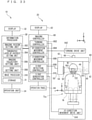
- Fig. 1 is a view illustrating a configuration of an X-ray tomography apparatus 10 according to an embodiment.
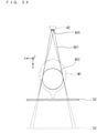
- Fig. 2 is a side view schematically illustrating an imaging unit 20 of the embodiment.
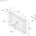
- Fig. 3 is a view conceptually illustrating a tomographic layer of interest LOI.
- a right-handed XYZ (X-axis, Y-axis, Z-axis) orthogonal coordinate system and a right-handed xyz (x-axis, y-axis, z-axis) orthogonal coordinate system are defined in Fig. 1 . Because a supporting relationship of a post 70 and a support 60 will be described in detail later, the detailed description is not made here, but the supporting relationship will be described in the minimum necessary range for explanation of each axial direction of a coordinate.
- the post 70 is erected on a base 7B placed on a ground on which the imaging unit 20 is installed, and an upper frame 64 includes a base end at a portion contacting with the post 70, and extends in one direction crossing a longitudinal direction of the post 70 from the base end.
- the upper frame 64 pivotally supports a turning unit 67 via a shaft 66.
- a turning axis 66A about which a turning arm 62 turns mechanically passes through the shaft 66.
- the axial direction of the turning axis 66A is a Z-axis direction.
- the X-ray tomography apparatus 10 in Fig. 1 is a standing type imaging apparatus.
- the Z-axis direction is a vertical direction, and is made to coincide with a body axis direction of a subject M1 positioned in the imaging unit 20.
- An arm 726 of a subject holder 72 has a base end in a portion contacting with the post 70, and extends in the same direction as the upper frame 64 from the base end.
- a head MH of the subject M1 is supported by a head support 72H such as a chin rest 722 provided on a leading end side of the arm 726.
- the post 70 extends in the Z-axis direction with respect to the base 7B.
- the base 7B spreads on the ground, and extends to at least a foot of the subject M1.
- each direction is defined on the assumption that the head MH is positioned and supported at a defined regular location by the head support 72H while facing in a regular direction.
- a front-rear direction of the head MH is a Y-axis direction
- a left-right direction of the head MH is an X-axis direction.
- the Z-axis direction is referred to as a Z-direction
- a Y-axis direction is referred to as a Y-direction
- an X-axis direction is referred to as an X-direction.
- a front of the head MH namely, the surface of the imaging unit 20 viewed from the direction in which the face is viewed from the front is set to the front of the imaging unit 20.
- Fig. 2 is a front view of the imaging unit 20.
- the upper frame 64 and the arm 726 extend in the X-direction (the -X-direction described below) from the post 70.
- the upper frame 64 and the arm 726 do not necessarily extend only in the X-direction.
- the upper frame 64 and the arm 726 may once extend in the Y-direction (the -Y-direction to be described below) and extend in the X-direction on the way.
- a + side and a ⁇ side in each axial direction will be described below.
- the direction from the head MH toward the base 7B, namely, a lower side is set to a -Z-side
- the direction away from the base 7B namely, an upper side is set to a +Z-side.
- the side supported by the upper frame 64 is the +Z-side
- the side supporting the turning arm 62 is the -Z-side.
- the direction in front of the head MH is set to a +Y-side
- the direction at the back of the head MH is set to a ⁇ Y-side.
- a right direction of the head MH is set to a +X-side
- a left direction is set to a -X-side.
- Each axial direction, each +, and each ⁇ are illustrated in a head perspective view MHPI that is a perspective view of the head MH in Fig. 1 .
- a visual line direction is defined as follows. In each axial direction, the direction viewed in ascending order of a numerical value is viewed as a + direction view, and the direction viewed in descending order of the numerical value is set to a ⁇ direction view.
- +ZV illustrated in the head perspective view MHPI is a +Z-direction view
- ⁇ ZV is a ⁇ Z-direction view
- +YV is a +Y-direction view
- -YV is a ⁇ Y-direction view
- +XV is a +X-direction view
- -XV is a -X-direction view.
- An xyz-orthogonal coordinate system is an orthogonal coordinate system defined in the turning arm 62 that rotates with respect to a portion (for example, the post 70) fixed in the imaging unit 20.
- the axial direction of the shaft 66 is set to a z-axis direction, and the z-axis direction is matched with the Z-axis direction of an XYZ-orthogonal coordinate system.
- a direction in which the X-ray generator 42 and the X-ray detector 52 are opposed to each other is set to a y-axis direction, and a direction orthogonal to the y-axis direction and the z-axis direction is set to an x-axis direction.
- the z-axis direction is referred to as a z-direction
- the y-axis direction is referred to as a y-direction
- the x-axis direction is referred to as an x-direction.
- the side of the X-ray detector 52 as viewed from the X-ray generator 42 is set to a +y-side.
- the right side toward the +y-side is set to a +x-side.
- the upper side in the vertical direction in the z-axis direction is set to a +z-side.
- the direction viewed in ascending order of the numerical value is referred to as the + direction view, and the direction viewed in descending order of the numerical value is referred to as the ⁇ direction view.
- the X-ray tomography apparatus 10 includes the imaging unit 20 and an information processor 30.
- the imaging unit 20 is an apparatus that collects X-ray projection data by performing X-ray tomography of the subject M1.
- the imaging unit 20 includes an X-ray generation unit 40, an X-ray detection unit 50, the support 60, the post 70, and an imaging controller 80.
- the X-ray generation unit 40 includes the X-ray generator 42 and an X-ray regulating unit 44.
- the X-ray generator 42 includes an X-ray tube that is an X-ray source that emits an X-ray. Intensity (output intensity) of an X-ray beam emitted from the X-ray generator 42 can be controlled by changing voltage and/or current supplied to the X-ray tube. Operation of the X-ray generator 42 is controlled by an X-ray generation controller 810 of the imaging controller 80.
- the X-ray regulating unit 44 regulates spread of the X-ray beam emitted from the X-ray generator 42, and forms the X-ray beam having a shape according to an imaging purpose. That is, the X-ray regulating unit 44 controls an X-ray irradiation range with respect to the subject M1 (examinee). The operation of the X-ray regulating unit 44 is controlled by the X-ray generation controller 810.
- the X-ray regulating unit 44 includes an X-ray shielding member disposed at a position close to the X-ray generator 42 and a moving mechanism (not illustrated) that moves the X-ray shielding member.
- the X-ray shielding member is constructed with a single plate member in which a plurality of openings having different opening shapes are provided or at least two plate members in which an opening having a required size or shape is formed by moving the plate members in an approaching or separating direction.
- the moving mechanism is constructed with a ball screw mechanism or a linear motor mechanism.
- the X-ray generator 42 and the X-ray regulating unit 44 are accommodated in a casing 46.
- the casing 46 is supported by the support 60 (in this case, the turning arm 62).
- the X-ray detection unit 50 includes the X-ray detector 52.
- the X-ray detector 52 detects an X-ray beam BX1 emitted from the X-ray generator 42.
- the X-ray detector 52 includes a flat panel detector (FPD) including a detection surface spreading in a flat shape or an X-ray image intensifier (I.I.).
- FPD flat panel detector
- I.I. X-ray image intensifier
- the plurality of detecting elements arranged on the detection surface of the X-ray detector 52 convert the intensity of the incident X-ray into an electric signal.
- the electric signal is input to the imaging controller 80 or the information processor 30 as an output signal, and an X-ray projection image is generated based on the output signal.
- the X-ray detector 52 is attached to a side portion of a casing 54 facing the X-ray generator 42, and the X-ray beam is emitted from the X-ray generator 42 to a detection surface of the X-ray detector 52.
- the casing 54 supporting the X-ray detector 52 is supported by the support 60 (in this case, the turning arm 62).
- the support 60 includes the turning arm 62 and the upper frame 64.
- the turning arm 62 is suspended from the upper frame 64 via the shaft 66.
- the casing 46 is attached to one end of the turning arm 62, and the casing 54 is attached to the other end of the turning arm 62. That is, the turning arm 62 supports the X-ray generator 42 at one end side with the casing 46 interposed therebetween, and supports the X-ray detector 52 at the other end side with the casing 54 interposed therebetween.
- the insides of the casings 46, 54 and the turning arm 62 form a series of cavities.
- Wirings (such as a signal wiring, a power supply wiring, and a control wiring) that operate each elements of the X-ray generation unit 40 and the X-ray detection unit 50 are disposed in the cavities.
- a working opening used to attach the wiring and a control board or an opening used to radiate heat may be provided at appropriate positions of the casings 46, 54 and the turning arm 62.
- the upper frame 64 is attached to the post 70.
- the shaft 66 extending in the Z-axis direction is attached to the upper frame 64, and the end of the shaft 66 is connected to an intermediate position between portions supporting the X-ray generation unit 40 and the X-ray detection unit 50 in the turning arm 62. Consequently, the turning arm 62 is suspended from the upper frame 64 via the shaft 66.
- a turning drive unit 642 is provided in the upper frame 64.
- the turning drive unit 642 rotates the shaft 66 to turn the turning arm 62 about the shaft 66.
- the turning drive unit 642 includes an endless belt entrained about the shaft 66 and a motor that rotates the endless belt.
- the turning drive unit 642 may be provided in the turning arm 62. In this case, the turning arm 62 rotates relative to the non-rotating shaft 66.
- the operation of the turning drive unit 642 is controlled by a turning controller.
- a turning axis 66A which is an axis on which the turning arm 62 turns mechanically, is set in the shaft 66 in design.
- the turning arm 62, the casing 46, and the casing 54 constitute a turning unit 67.
- the upper frame 64 is a turning support 64A that supports the turning unit 67 via the shaft 66.
- the turning arm 62 turns about the axis of the shaft 66, whereby the turning unit 67 turns about the turning axis 66A.
- the turning arm 62 supports the casing 46 at one end side, and supports the casing 54 at the other end side. Consequently, a part of the turning arm 62 supports the X-ray generator 42 while another part supports the X-ray detector 52, the turning axis 66A being sandwiched between the parts. That is, the support 60 supports the X-ray generator 42 and the X-ray detector 52.
- An XY-direction movement drive unit 644 that moves the shaft 66 in the X-axis direction and the Y-axis direction is provided in the upper frame 64.
- the XY-direction movement drive unit 644 is constructed with an XY-stage.
- the XY-direction movement drive unit 644 moves the turning drive unit 642 in the X-axis direction and the Y-axis direction together with the shaft 66. For this reason, the shaft 66 is movable in the XY-plane, and is rotatable about the axis in the Z-axis direction at a specific position after the movement in the XY-plane.
- the XY-direction movement drive unit 644 may be provided in the turning arm 62.
- the turning arm 62 moves in the X-axis direction and the Y-axis direction relative to the shaft 66 fixed at a constant position in the XY-plane.
- Both of the turning drive unit 642 and the XY-direction movement drive unit 644 may be provided in the turning arm 62.
- the turning arm 62 moves relatively in the X-axis direction and the Y-axis direction and rotates relatively with respect to the shaft 66, which is fixed at the constant position in the XY-plane and does not rotate.
- a Z-direction drive unit 646 that elevates and lowers the upper frame 64 in the Z-axis direction is provided in the upper frame 64 and the post 70.
- the Z-direction drive unit 646 includes a motor 6462, a ball screw 6464, a nut 6466, and a plurality (in this case, four) of rollers 6468.
- the motor 6462 rotates the ball screw 6464.
- the ball screw 6464 extends in the Z-axis direction.
- the nut 6466 is screwed in the ball screw 6464.
- Each of the rollers 6468 is engaged with a pair of rails 702 provided on the post 70, and the movement direction of the roller 6468 is restricted such that the roller 6468 moves only in the extending direction (Z-axis direction) of the pair of rails 702.
- the motor 6462 is attached to the post 70, and the nut 6466 is fixed to the upper frame 64.
- Each roller 6468 is attached to the upper frame 64.
- the motor 6462 rotates the ball screw 6464 clockwise or counterclockwise, whereby the nut 6466 moves upward or downward along the ball screw 6464.
- the rollers 6468 move on the pair of rails 702. Consequently, the upper frame 64 is elevated and lowered in the Z-axis direction.
- the X-ray generation unit 40 and the X-ray detection unit 50 which are supported by the turning arm 62, move in the Z-axis direction in association with the elevating and lowering movement of the upper frame 64.
- the post 70 is a member extending in the Z-axis direction, and supports the upper frame 64 and the subject holder 72.
- the subject holder 72 is a member that holds the subject M1.
- the subject holder 72 includes the chin rest 722, a lower frame 724, the arm 726, and an elevation drive unit 728.
- the chin rest 722 supports a jaw of the subject M1 to support the head of the subject M1.
- the subject holder 72 is connected to the lower frame 724 via the arm 726.
- the subject holder 72 may include a member (an ear rod or an arm sandwiching the left and right of the head of the subject M1) such as an ear rod that fixes the head of the subject M1 from both sides.
- the lower frame 724 is attached to the post 70, and moves in the Z-axis direction.
- the lower frame 724 moves in the Z-axis direction, whereby the chin rest 722 fixed to the arm 726 moves in the Z-axis direction.
- the arm 726 is a member that connects the lower frame 724 and the chin rest 722.
- the arm 726 is constructed with a portion extending in parallel to the XY-plane from the lower frame 724 and a portion, which extends to the Z-axis and is connected to the chin rest 722.
- the elevation drive unit 728 includes a motor 7282, a ball screw 7284, a nut 7286, and a plurality of (four in this case) rollers 7288.
- the motor 7282 rotates the ball screw 7284.
- the ball screw 7284 extends in the Z-axis direction.
- the nut 7286 is screwed in the ball screw 7284.
- Each of the rollers 7288 is engaged with the pair of rails 702, and the moving direction of the roller 7288 is restricted so as to move only in the extending direction (Z-axis direction) of the pair of rails 702.
- the motor 7282 and the ball screw 7284 are fixed to the lower frame 724.
- the nut 7286 is fixed to the upper frame 64.
- the ball screw 7284 extends in the +Z direction from a top of the lower frame 724, and is screwed in the nut 7286 fixed in the vicinity of the bottom of the upper frame 64.
- Each of the rollers 7288 is attached to the lower frame 724.
- the lower frame 724 moves in the Z-axis direction, whereby the chin rest 722 moves along the Z-axis.
- the support 60 is elevated and lowered with respect to the head MH by the relative movement while the height of the head MH is kept constant, which allows the X-ray irradiation location to be changed in the Z-axis direction.
- the support 60 is elevated and lowered together with the subject holder 72 according to the position of the head MH of the subject M1 using the Z-direction drive unit 646 to fix the head MH to the head support 72H.
- the subject holder 72 may be lowered using the elevation drive unit 728 by the same drive amount relative to the support 60.
- the subject holder 72 may be raised using the elevation drive unit 728 by the same drive amount relative to the support 60 while the support 60 is lowered using the Z-direction drive unit 646.
- the position where the head of the subject M1 is supported may be changed by changing the position in the Z-axis direction of the chin rest 722.
- the position of the chin rest 722 is set according to the position of the head of the subject M1 in an upright posture.
- the imaging controller 80 controls the operation of each element of the imaging unit 20 to cause the imaging unit 20 to perform the X-ray tomography.
- a hardware configuration of the imaging controller 80 is similar to that of a general computer or a work station. That is, the imaging controller 80 includes a CPU that performs various arithmetic processing, a ROM that is a read-only memory in which a basic program is stored, a RAM that is a readable and writable memory in which various pieces of information are stored, and a storage in which a control application or data is stored.
- the imaging controller 80 includes a turning controller 802, an XY-direction movement controller 804, a Z-direction movement controller 806, an X-ray detection controller 808, and an X-ray generation controller 810.
- Each controller is a function implemented by the operation of the CPU (general-purpose circuit) according to the controlling application. A part or all of the functions may be implemented in a hardware manner by construction of a dedicated circuit.
- portions used for various kinds of control by various control applications may be grasped as the controllers 802, 804, 806, 808, and integration thereof may be grasped as the imaging controller 80.
- the turning controller 802 controls the turning of the turning arm 62 by controlling the operation of the turning drive unit 642. Specifically, the turning controller 802 changes an irradiation angle of an X-ray beam BX1 with respect to the subject M1 by rotating the X-ray generator 42 supported by the turning arm 62 around the shaft 66.
- the XY-direction movement controller 804 controls the movement of the turning arm 62 in the X- and Y-axis directions as a result of the movement of the shaft 66 in the X-axis direction and the Y-axis direction. Specifically, the XY-direction movement controller 804 moves the X-ray generator 42 and the X-ray detector 52 in the X-axis direction and the Y-axis direction.
- the turning drive unit 642 and the XY-direction movement drive unit 644 constitute a turning movement drive unit 64D
- the turning controller 802 and the XY-direction movement controller 804 constitute a turning movement drive controller 80D.
- the Z-direction movement controller 806 controls the movement of the turning arm 62 in the Z-direction by controlling the operation of the Z-direction drive unit 646. Specifically, the Z-direction movement controller 806 moves the X-ray generator 42 and the X-ray detector 52 in the Z-direction.
- the X-ray detection controller 808 controls the operation of the X-ray detection unit 50.
- the X-ray detection controller 808 controls the operation of the X-ray detector 52.
- the X-ray generation controller 810 controls the operation of the X-ray generation unit 40.
- the X-ray generation controller 810 controls the operation of the X-ray generator 42. Specifically, on and off of the X-ray beam emitted from the X-ray generator 42 and the intensity of the X-ray beam are controlled by controlling the voltage or current supplied to the X-ray tube.
- the X-ray generation controller 810 controls shielding of the X-ray beam by controlling the operation of the X-ray regulating unit 44.
- the X-ray beam (such as an X-ray narrow beam and an X-ray cone beam) having the shape according to the imaging purpose is formed by the shielding control of the X-ray beam.
- the X-ray generation controller 810 controls the operation of the X-ray regulating unit 44 to prevent the region other than an imaging region ROI in the subject M1 from being irradiated with the X-ray beam.
- a display 82 and an operation panel 84 are connected to the imaging controller 80.
- the display 82 is constructed with a liquid crystal display or the like, and provided to display various pieces of information.
- the operation panel 84 is configured of a touch panel display, and is provided for an operator to input various pieces of information (including an imaging condition) to the imaging controller 80.
- the information processor 30 is connected to the imaging controller 80 so as to be capable of communicating information.
- a hardware configuration of the information processor 30 is similar to that of a general computer or a work station. That is, the information processor 30 includes a CPU that performs various pieces of arithmetic processing, a ROM that is a read-only memory in which a basic program is stored, a RAM that is a readable and writable memory in which various pieces of information are stored, and a storage 31 in which an application or data is stored.
- the information processor 30 includes an imaging region setting unit 302, a tomographic layer-of-interest setting unit 304, an imaging trajectory setting unit 306, a dose setting unit 308, and an image processor 310.
- Each processor is a function implemented by the operation of the CPU according to the application. However, some or all of these functions may be realized in hardware by a dedicated circuit.
- portions used for various kinds of control by various control applications may be grasped as the setting units 302, 304, 306, 308, 310, and integration thereof may be grasped as the information processor 30.
- the imaging region setting unit 302 has a function of setting the imaging region ROI.
- the imaging region ROI is a region that, when the imaging unit 20 performs the X-ray tomography, is irradiated with the X-ray beam from a plurality of directions to acquire a plurality of X-ray projection images.
- the imaging region setting unit 302 sets the imaging region ROI based on an input operation input by the operator through the operation unit 34.
- a virtual space on arithmetic operation corresponding to a real space of the imaging unit 20 is defined in the information processor 30.
- the setting of the imaging region ROI means the setting of a position, a size, a shape, and the like of the imaging region ROI in the virtual space defined in the information processor 30. A specific method for setting the imaging region ROI will be described later.
- the tomographic layer-of-interest setting unit 304 has a function of setting a tomographic layer of interest LOI.
- the tomographic layer of interest LOI is usually a tomographic layer on which the operator wants to perform the imaging.
- the tomographic layer-of-interest setting unit 304 sets the tomographic layer of interest LOI based on the information input to the information processor 30 by the operator through the operation unit 34. "The setting of the tomographic layer of interest LOI" means the setting of the tomographic layer of interest LOI in the virtual space defined by the information processor 30.
- the tomographic layer of interest LOI is set by the following procedure. That is, as illustrated in Fig. 3 , the tomographic layer-of-interest setting unit 304 determines the position, the size, and an orientation (normal direction DN1) of a tomographic plane of interest SL1 based on the operation input of the operator. The tomographic layer-of-interest setting unit 304 sets the tomographic layer of interest LOI having a required thickness in the normal direction DN1 based on the tomographic plane of interest SL1. In the example of Fig. 3 , the tomographic layer of interest LOI having a thickness TN1 in the normal direction DN1 is set around the tomographic plane of interest SL1.
- the thickness TN1 of the tomographic layer of interest LOI may be set based on designated input from the operator, or may be a predetermined specified value.
- the thickness TN1 is the specified value, for example, the position of the tomographic layer of interest LOI, characteristics (such as a height, a weight, age, and gender) of the subject, or the specified value according to an imaging site can previously made into a database, stored in the storage 31, and called according to the imaging. A more specific method for setting the tomographic layer of interest LOI will be described later.
- the imaging trajectory setting unit 306 has a function of setting trajectories (imaging trajectories) of the X-ray generator 42 and the X-ray detector 52 during the X-ray tomography when the imaging unit 20 performs the X-ray tomography. Specifically, in the imaging trajectory setting unit 306, a turning center axis RA1 parallel to the Z-axis passing through the center of the imaging region ROI is set to the rotation center, and a circular trajectory when the X-ray generator 42 and the X-ray detector 52 are rotated about the turning center axis RA1 at a predetermined rotation radius is set to a normal imaging trajectory.
- the imaging trajectory setting unit 306 changes the normal imaging trajectory according to the position of the tomographic layer of interest LOI set by the tomographic layer-of-interest setting unit 304. Specifically, the imaging trajectory setting unit 306 changes the normal imaging trajectory to determine the final imaging trajectory such that the X-ray generator 42 is moved away from the tomographic layer of interest LOI and the X-ray detector 52 approaches the tomographic layer of interest LOI when the X-ray generator 42 confronts the tomographic layer of interest LOI. The setting of the imaging trajectory will be described later.
- the dose setting unit 308 sets a dose per unit time (a unit time dose) with which the imaging region ROI of the subject M1 including the tomographic layer of interest LOI is irradiated during the X-ray tomography performed in the imaging unit 20. Specifically, the dose setting unit 308 generates dose control data for operating the imaging controller 80 such that at least a part of the unit time dose in the period in which the X-ray generator 42 does not confront the tomographic layer of interest LOI is smaller than the unit time dose in the period in which the X-ray generator 42 confronts the tomographic layer of interest LOI.
- the dose setting unit 308 when considering relatively, the dose setting unit 308 generates the dose control data for operating the imaging controller 80 such that the unit time dose in the period in which the X-ray generator 42 confronts the tomographic layer of interest LOI is larger than at least a part of the unit time dose of the period in which the X-ray generator 42 does not confront the tomographic layer of interest LOI.
- the setting of the unit time dose will be described later.
- the thickness direction of the thickness TN1 may be matched with the Y-direction, and a width direction of the width W1 may be matched with the X-direction.
- the vectors in the X- and Y-directions may be adapted for each region.
- the image processor 310 processes the X-ray projection image, which is generated based on the signal output by the X-ray detector 52 when the imaging unit 20 performs the X-ray tomography, and generates an X-ray tomographic image of the tomographic layer of interest LOI.
- the X-ray tomographic image generated by the image processor 310 is not limited to the X-ray tomographic image of the tomographic layer of interest LOI.
- the operator may receive designation of another tomographic layer at a position different from the tomographic layer of interest LOI in the imaging region ROI, and the image processor 310 may generate the X-ray tomographic image corresponding to the tomographic layer.
- the imaging controller 80 makes the unit time dose in the period in which the X-ray generator 42 does not confront the tomographic layer of interest LOI relatively smaller than the unit time dose in the period in which the X-ray generator 42 confronts the tomographic layer of interest LOI during the X-ray tomography.
- the image processor 310 may perform smoothing processing (blurring processing) on the X-ray projection image obtained by the irradiation of the unit time dose smaller than a predetermined threshold.
- a smoothing filter such as a moving average filter and a Gaussian filter having a required radius may be used.
- the smoothing processing may be performed in both the case where the X-ray generator 42 confronts the tomographic layer of interest LOI and the case where the X-ray generator 42 does not confront the tomographic layer of interest LOI.
- the size of the radius of the smoothing filter in the smoothing processing may be changed according to a projection angle, the thickness of the tomographic layer, or the magnitude of the unit time dose. The change in the size of the smoothing will be described later.
- the display 32 and the operation unit 34 are connected to the information processor 30.
- the display 32 is constructed with a liquid crystal display or the like, and provided to display various pieces of information. Specifically, the display 32 displays a display image with which the operator designates a condition of the X-ray tomography, a display image with which the operator designates the imaging region ROI or the tomographic layer of interest LOI, and the X-ray tomographic image generated by the image processor 310.
- the operation unit 34 is constructed with various input devices such as a keyboard and a mouse. As an example, the operation unit 34 is operated when the operator designates the imaging region ROI. That is, the operation unit 34 is an example of an imaging region designation unit.
- the display 32 may have a part or all of the functions of the operation unit 34 by constructing the display 32 with a touch panel.
- the imaging region ROI and the tomographic layer of interest LOI may be designated through the operation panel 84 connected to the imaging controller 80.
- a method for setting the tomographic layer of interest LOI or the imaging region ROI will be described below with reference to Figs. 4 to 8 .
- the tomographic layer of interest LOI or the imaging region ROI is set to the jaw in the head of the subject M1.
- the tomographic layer of interest LOI or the imaging region ROI is not limited to the case where the tomographic layer of interest LOI or the imaging region ROI is set to the jaw, and may be set to another site.
- Fig. 4 is a view illustrating the method for setting the tomographic layer of interest LOI.
- the display 32 displays a schematic diagram IL1 that simulates a lower jaw as a designation image for designating the tomographic layer of interest LOI.
- a plurality of teeth are also drawn in the schematic diagram IL1.
- the operator designates two end points EP1, EP2 with respect to the schematic diagram IL1 displayed on the display 32 using a cursor CU1.
- the end points EP1, EP2 may be designated by moving the cursor CU1 through a drag operation.
- the positions of the end points EP1, EP2 correspond to the positions of two points in the XY-plane in the real space.
- the linear tomographic plane of interest SL1 having end points EP1, EP2 at both ends is set when the two end points EP1, EP2 are designated (see Fig. 3 ).
- the end points EP1, EP2 have a width W1 of the tomographic plane of interest SL1.
- the end points EP1, EP2 are not necessarily set to both ends.
- the tomographic plane of interest SL1 having any width may be set on a straight line passing through the end points EP1, EP2.
- the linear tomographic layer of interest LOI having the required thickness TN1 in the normal direction DN1 is set based on the tomographic plane of interest SL1.
- a length (vertical width W2) in a depth direction (corresponding to the Z-axis direction of the real space) of the tomographic layer of interest LOI) is also set appropriately.
- the vertical width W2 of the tomographic layer of interest LOI may be designated by the operator, or automatically determined according to the physical characteristics (such as the gender, the age, the height, and the weight) or the imaging site of the subject M1 by the tomographic layer-of-interest setting unit 304.
- Fig. 5 is a view illustrating the method for setting the tomographic layer of interest LOI.
- the tomographic layer of interest LOI is set to the shape extending linearly in the XY-plane.
- the tomographic layer of interest LOI may be set to a curved shape.
- the tomographic layer-of-interest setting unit 304 may set the tomographic plane of interest SL1 to the curved shape according to the movement trajectory of the cursor CU1.
- the tomographic layer-of-interest setting unit 304 may set the tomographic layer of interest LOI extending in the curved manner based on the tomographic plane of interest SL1.
- Fig. 6 is a view illustrating the method for setting the tomographic layer of interest LOI.
- the operator sets the tomographic layer of interest LOI to any position.
- a plurality of candidate regions that are candidates of the tomographic layer of interest LOI are previously specified, and the operator selects the tomographic layer of interest LOI from among these candidate regions.
- seven candidate regions CR1 are previously determined in the schematic diagram IL1 of the jaw displayed on the display 32, and each candidate region CR1 is displayed by a broken line.
- the tomographic layer-of-interest setting unit 304 sets the selected candidate region CR1 to the tomographic layer of interest LOI.
- the designation operation of the tomographic layer of interest LOI can easily be performed.
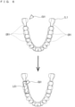
- Fig. 7 is a view illustrating the method for setting the imaging region ROI and the tomographic layer of interest LOI.
- the operator directly designates the tomographic layer of interest LOI on the designation image.
- the tomographic layer-of-interest setting unit 304 automatically sets the tomographic layer of interest LOI according to the imaging region ROI.
- the imaging region ROI may be set as follows. That is, the operator designates the position of the imaging region ROI (for example, the center position of the imaging region ROI) and the radius of the imaging region ROI using the cursor CU1 or the like. In response to the designation, the imaging region setting unit 302 sets the imaging region ROI having the designated radius at the designated position.
- the radius of the imaging region ROI may be designated by numerical input through the keyboard or the like, or designated by the drag operation using the mouse. Circular frames having various radii indicating the size of the imaging region ROI may previously be prepared, and the operator may select the frame having the specific radius from among the circular frames. In this case, the imaging region setting unit 302 may set the imaging region ROI at the position where the selected frame is disposed according to the disposition of the selected frame at the required position on the schematic diagram IL1.
- the tomographic layer-of-interest setting unit 304 automatically sets the tomographic layer of interest LOI according to a predetermined rule for the set imaging region ROI.
- the tomographic layer-of-interest setting unit 304 may set the tomographic layer of interest LOI based on a dental arch DA1 defined along the jaw.
- a dental arch DA1 defined along the jaw.
- the dental arch DA1 curved into a U-shape is defined in the schematic diagram IL1 of the jaw, and that the imaging region ROI is set so as to include the dental arch DA1.
- the tomographic layer-of-interest setting unit 304 may automatically set the tomographic layer of interest LOI along a part of the dental arch DA1 included in the imaging region ROI.
- the linear tomographic layer of interest LOI When the linear tomographic layer of interest LOI is set from the curved dental arch DA1, for example, a point on the portion of the dental arch DA1 of the imaging region ROI is taken as a representative point, and the tomographic layer of interest LOI may be set on a tangential line on the representative point of the dental arch DA1. Two points on a portion of the dental arch DA1 in the imaging region ROI may be selected, and the tomographic layer of interest LOI may be set on a straight line connecting the two points.
- the curved tomographic layer of interest LOI of the tomographic layer-of-interest setting unit 304 may be set based on the curved dental arch DA1.
- a curved portion of the dental arch DA1 in the imaging region ROI may be set to the tomographic plane of interest SL1, and a region having a predetermined thickness based on the curved portion may be set to the tomographic layer of interest LOI.
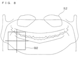
- Fig. 8 is a view illustrating the method for setting the tomographic layer of interest LOI.
- a panoramic X-ray image IL2 obtained by previously performing panoramic imaging of the jaw of the subject M1 is used as the designation image.
- the panoramic X-ray image IL2 is displayed on the display 32, and the tomographic layer of interest LOI or the imaging region ROI is set on the panoramic X-ray image IL2.
- Each pixel constituting the panoramic X-ray image IL2 has information about a coordinate position on the real space. For this reason, the coordinate position corresponding to the specific portion in the real space is specified when a specific portion on the panoramic X-ray image IL2 is selected using a cursor CU2.
- the cursor CU2 includes two straight lines orthogonal to each other.
- the operator aligns the intersection of the two straight lines with the site to be observed, namely, the tomographic layer of interest LOI, and performs the operation (such as a mouse click operation) to specify the position.
- the tomographic layer-of-interest setting unit 304 appropriately sets the linear or curved tomographic layer of interest LOI.
- the methods for setting the tomographic layer of interest LOI in Figs. 4 to 8 is merely illustrative.
- the present invention is not limited to the methods in Figs. 4 to 8 , and the tomographic layer of interest LOI may be set by another method.
- a plurality of X-ray projection images (fluoroscopic images) obtained by irradiating the subject M1 with the X-ray beam BX1 from a plurality of directions may be used as the designation image for designating the imaging region ROI or the tomographic layer of interest LOI.
- the coordinate position on the real space corresponding to the designated position can be specified by receiving the designation of the position of the imaging region ROI or the tomographic layer of interest LOI on two fluoroscopic images obtained by imaging the subject M1 from two directions.
- the technique described in Japanese Patent Application Laid-Open No. 2004-329293 may be used when the coordinate position in the real space is specified from the fluoroscopic images in the two directions.
- the imaging region setting unit 302 may set the imaging region ROI according to the tomographic layer of interest LOI. At this point, the imaging region ROI may be set such that the imaging region setting unit 302 includes the previously-set tomographic layer of interest LOI.
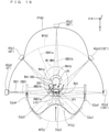
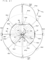
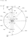
- Fig. 9 is a view illustrating an example of the X-ray tomography.
- Fig. 9 is a view illustrating a positional relationship among the X-ray generator 42, the X-ray detector 52, and the subject M1 during the X-ray tomography as viewed from the +Z-side (in Z-direction view). The same applies to Figs. 13 and 16 .
- the X-ray tomography in Fig. 9 is CT imaging in which the X-ray generator 42 and the X-ray detector 52 are turned by 180° around the subject M1. A portion including the front teeth is set to the imaging region ROI, and a region extending linearly along the tangential line of a part of the dental arch DA1 included in the imaging region ROI is set to the tomographic layer of interest LOI.
- the X-ray generator 42 is turned from a position 42p0 on the right side of the head to a position 42p4 on the left side of the head through a position 42p1 to a position 42p3 on a rear side of the head.
- the X-ray detector 52 is turned from a position 52p0 on the left side of the head to a position 52p4 on the right side of the head through a position 52p1 to a position 52p3 on a front side of the head.
- An imaging trajectory LT42 (NT42) of the X-ray generator 42 and an imaging trajectory LT52 (NT52) of the X-ray detector 52 are matched with an arc of a semicircle having a predetermined radius centered on a center point CP1 of the imaging region ROI.
- the imaging trajectory LT42 of the X-ray generator 42 and the imaging trajectory LT52 of the X-ray detector 52 will be described.
- the imaging trajectory LT42 of the X-ray generator 42 is a higher-level concept including both a normal imaging trajectory NT42 of the X-ray generator 42 (to be described later) and a magnification factor adjustment imaging trajectory PT42. That is, the imaging trajectory LT42 may be the normal imaging trajectory NT42 or the magnification factor adjustment imaging trajectory PT42.
- the imaging trajectory LT52 of the X-ray detector 52 is a higher-level concept including both a normal imaging trajectory NT52 of the X-ray detector 52 (to be described later) and a magnification factor adjustment imaging trajectory PT52. That is, the imaging trajectory LT52 may be the normal imaging trajectory NT52 or the magnification factor adjustment imaging trajectory PT52.
- the turning of the X-ray generator 42 rotates the X-ray beam BX1 advancing from the X-ray generator 42 to the X-ray detector 52.
- the angle projected onto the detection surface of the X-ray detector 52 changes with respect to the imaging region ROI.
- the time of start of the X-ray tomography means the time when the X-ray detector 52 detects the X-ray beam BX1 transmitted through the subject M1 to start the acquisition of the X-ray projection image.
- the X-ray generator 42 is disposed at the position 42p0 at the beginning of the X-ray tomography. For this reason, the projection angle when the X-ray generator 42 is located at the position 42p0 is 0°.
- the projection angle when the X-ray generator 42 is located at the position 42p2 is 90°, and the projection angle when the X-ray generator 42 is located at the position 42p4 is 180°.
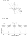
- Fig. 10 is a view illustrating the center axis X-ray CBX1 incident on the tomographic layer of interest LOI.
- a state in which the center axis X-ray CBX1 is incident on the tomographic layer of interest LOI at substantially right angles means a state in which the X-ray generator 42 confronts the tomographic layer of interest LOI (in other words, the irradiation axis of the X-ray beam BX1 is incident on the tomographic layer of interest LOI in a confronting manner).
- incident at substantially right angles means the state in which an incident angle ANG1 of the center axis X-ray CBX1 with respect to the tomographic layer of interest LOI is in a range of 85° to 95°, namely, a range of 90° ⁇ 5° to 90° + 5°, and in particular, in the state in which the center axis X-ray CBX1 is incident at right angles means the state in which the incident angle ANG1 becomes 90°. Needless to say, incident at right angles such as 90° is orthogonal. Incident at substantially right angles may also be referred to as “substantially orthogonal”.
- An extent to which the range of the substantially right angle is set can be appropriately adjusted from experience of image processing, and may be slightly wider or narrower than 85° to 95°.
- the range of 82° to 98° and the range of 88° to 92° can also be considered.
- the incident angle ANG1 means an angle around a turning direction RD1 of the X-ray generator 42 from a center line LL1 to the center axis X-ray CBX1 when the center line LL1 passing through the center of the tomographic layer of interest LOI is defined as viewed from the upper side in the Z-axis direction, namely, in Z-direction view.
- the X-ray generator 42 rotates clockwise with respect to the subject M1 as viewed from the +Z-side, that is, in -Z-direction view.
- the incident angle ANG1 is a clockwise angle from the center line LL1 to the center axis X-ray CBX1.
- the tangential line on the tomographic layer of interest LOI and at any point (for example, a barycentric point of the curve) on the curve along the tomographic layer of interest LOI is set to the center line LL1, and the angle between the center axis X-ray CBX1 and the center line LL1 is set to the incident angle ANG1.
- the incident angle ANG1 is 0°.
- the incident angle ANG1 is 90°.
- the incident angle ANG1 is 180°. That is, in this example, the X-ray generator 42 confronts the tomographic layer of interest LOI when passing through the position 42p2.
- the imaging trajectory setting unit 306 sets the normal imaging trajectories NT42, NT52 of the X-ray generator 42 and the X-ray detector 52. Specifically, the imaging trajectory setting unit 306 sets the normal imaging trajectories NT42, NT52 such that each of the X-ray generator 42 and the X-ray detector 52 moves on a circumference of a semicircle having a predetermined radius centered on the center point CP1 of the imaging region ROI.
- the dose setting unit 308 sets the unit time dose corresponding to the projection angle of the X-ray with which the subject M1 is irradiated during the CT imaging in Fig. 9 . Specifically, the dose setting unit 308 generates the dose control data for operating the imaging controller 80 such that the unit time dose in the period in which the X-ray generator 42 does not confront the tomographic layer of interest LOI is smaller than the unit time dose in the period in which the X-ray generator 42 confronts the tomographic layer of interest LOI.
- the dose setting unit 308 generates the dose control data for operating the imaging controller 80 such that the unit time dose in the period in which the X-ray generator 42 confronts the tomographic layer of interest LOI is larger than the unit time dose in the period in which the X-ray generator 42 does not confront the tomographic layer of interest LOI.
- a method for changing the unit time dose includes a method in which the X-ray generation controller 810 changes the X-ray intensity of the X-ray beam BX1 output from the X-ray generator 42 and a method in which turning movement drive controller 80D (in particular, the turning controller 802 for the turning of the turning arm 62) changes the turning velocity of the X-ray generator 42 (the angular velocity of the turning arm 62).
- the dose setting unit 308 may generate the dose control data for operating the X-ray generation controller 810.
- the dose setting unit 308 may generate the dose control data for operating the turning movement drive controller 80D.
- the unit time dose may be changed by changing both the X-ray intensity and the turning velocity.
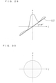
- Fig. 11 is a view illustrating a graph G10 of the X-ray intensity corresponding to the projection angle in the CT imaging of Fig. 9 .
- a horizontal axis indicates the projection angle
- a vertical axis indicates the X-ray intensity.
- the X-ray intensity in the period in which the X-ray generator 42 does not confront the tomographic layer of interest LOI (the state in which the irradiation axis of the X-ray beam BX1 is incident on the tomographic layer of interest LOI in the confronting manner, for example, the projection angles of 0°, 45°, 135° and 180°) is smaller than the X-ray intensity in the period in which the X-ray generator 42 confronts the tomographic layer of interest LOI (when the projection angle is 90°).
- the projection angles of 0°, 45°, 135° and 180° is smaller than the X-ray intensity in the period in which the X-ray generator 42 confronts the tomographic layer of interest LOI (when the projection angle is 90°).
- the X-ray intensity is set to I0 at the projection angles between 0° and 45°, and the X-ray intensity is increased from I0 to I1 until the projection angle reaches 90° after passing through about 45°. That is, the X-ray intensity is increased from I0 to I1 until the incident angle ANG1 reaches 90°.
- the X-ray intensity is decreased from I1 to I0 until the projection angle reaches 135° after exceeding 90°, and the X-ray intensity is maintained at I0 until the projection angle becomes 180°. That is, the X-ray intensity is decreased from I1 to I0 after the incident angle ANG1 exceeds 90°.
- the dose setting unit 308 generates the dose control data that causes the X-ray generation controller 810 to change the X-ray intensity according to the projection angle in Fig. 11 .
- the change curve (graph G10) of the X-ray intensity from the increase in the X-ray intensity from I0 to I1 to the decrease in the X-ray intensity again from I1 to I0 has a line symmetrical shape with the axis passing through the projection angle of 90° in the confronting state as a symmetrical axis.
- Fig. 12 is a view illustrating a graph G12 of the turning velocity of the X-ray generator 42 corresponding to the projection angle in the CT imaging of Fig. 9 .
- the horizontal axis indicates the projection angle
- the vertical axis indicates the turning velocity (angular velocity).
- the turning velocity is set to V0 at the projection angles between 0° and 45°, and the turning velocity is decreased from V0 to V1 until the projection angle reaches 90° after passing through about 45°. That is, the turning velocity is decreased from V0 to V1 until the incident angle ANG1 reaches 90°. Then, the turning velocity is increased from V1 to V0 until the projection angle reaches 135° after exceeding 90°, and the X-ray intensity is maintained at V0 until the projection angle becomes 180°. That is, the turning velocity is increased from V1 to V0 after the incident angle ANG1 exceeds 90°.
- the dose setting unit 308 generates the dose control data for causing the turning movement drive controller 80D, in this case, the turning controller 802, to change the turning velocity according to the projection angle in Fig. 12 .
- the turning velocity when the turning velocity is set to V0 at the projection angle of 0°, the X-ray generator 42 starts the turning from the position in front of the position 42p0, and the turning velocity may be increased to V0 until the X-ray generator 42 passes through the position 42p0.
- the X-ray generator 42 may start the turning from the position 42p0.
- the turning velocity may be increased from 0 to V0 until the projection angle becomes from 0° to a predetermined angle.
- the unit time dose in the period in which the X-ray generator 42 does not confront the tomographic layer of interest LOI can be set smaller than the unit time dose in the period in which the X-ray generator 42 confronts the tomographic layer of interest LOI. Consequently, the X-ray projection image can be acquired with high resolution when the tomographic layer of interest LOI is projected from the front surface. Thus, the X-ray tomographic image of the tomographic layer of interest LOI suitable for an image diagnosis can be generated.
- the X-ray exposure dose of the subject M1 can be decreased by suppressing the unit time dose in the period in which the X-ray generator 42 does not confront the tomographic layer of interest LOI to a low level.
- the unit time dose is lower than that in the conventional CT imaging except for when the X-ray generator 42 confronts the tomographic layer of interest LOI.
- circuit binning or image processing binning is performed in the X-ray detector 52.
- the binning is performed, the resolution may be degraded.
- the unit time dose is increased but the binning is not performed.
- the unit time dose in the period in which the X-ray generator 42 confronts the tomographic layer of interest LOI may be the same as that in the conventional CT imaging.
- the total exposure dose of the subject M1 in the CT imaging can be suppressed to a lower level as compared to the conventional technique.
- the unit time dose in the period in which the X-ray generator 42 confronts the tomographic layer of interest LOI may be increased larger than that in the past in order to improve the image quality (resolution) of the tomographic image of the tomographic layer of interest LOI.
- the unit time dose in the period in which the X-ray generator 42 does not confront the tomographic layer of interest LOI is decreased such that the total exposure dose of the subject M1 becomes smaller than that in the past.
- setting the unit time dose in the period in which the X-ray generator 42 confronts the tomographic layer of interest LOI larger than the unit time dose in the period in which the X-ray generator 42 does not confront the tomographic layer of interest LOI is the same as setting the unit time dose in the period in which the X-ray generator 42 does not confront the tomographic layer of interest LOI smaller than the unit time dose in the period in which the X-ray generator 42 confronts the tomographic layer of interest LOI.
- the turning is started from the position where the incident angle ANG1 becomes 0°.
- the turning is not necessarily started from the position where the incident angle ANG1 becomes 0°.
- the turning of the X-ray generator 42 may be started from the position where the incident angle ANG1 becomes an angle larger than 0° or the position where the incident angle ANG1 becomes an angle smaller than 0° (the position where the center axis X-ray CBX1 is emitted on the opposite side to the confronting side with respect to the tomographic layer of interest LOI).
- the unit time dose in the period in which the X-ray generator 42 confronts the tomographic layer of interest LOI namely, in the period in which the X-ray generator 42 is located at the position 42p2 is similarly increased larger than the unit time dose in the period in which the X-ray generator 42 does not confront the tomographic layer of interest LOI.
- the rotation of the X-ray generator 42 may be started from the near side in the rotational direction with respect to the position 42p0, and the emission of the X-ray beam BX1 may be started after the X-ray generator 42 reaches the position 42p0.
- a range that is not so close to the right angle as the substantially right angle, but is close to the right angle is referred to as a "near right angle”.
- Incidence in which the incident angles are the near right angle may be referred to as "near orthogonal incidence”.
- a range of a difference on the small side or the large side with respect to the orthogonal state is set to an angle Iao.
- the angle Iao is 5° when the substantially right angle ranges from 90° ⁇ 5° to 90° + 5°.
- the range of the near right angle can be defined in various ways, for example, 90° ⁇ 30° to 90° ⁇ angle Iao, 90° + angle Iao to 90° + 30°, 90 ° ⁇ 15° to 90° ⁇ angle Iao, and 90° + angle Iao to 90° + 15°.
- the period during which the X-ray intensity is maintained at intensity I1 in Fig. 11 and the period during which the turning velocity is maintained at velocity V1 in Fig. 12 may have a width.
- the pattern may be changed.
- the following control can be considered.
- At least setting the X-ray intensity to the intensity I1 at the orthogonal timing, and/or setting the turning velocity to velocity VI, and setting the X-ray strength to the strength lower than the strength I1 at at least a part of the period that is out of the orthogonal timing, and/or setting the turning velocity to the velocity higher than the velocity V1 are common. These variations can also be applied to tomosynthesis imaging (to be described later).
- the X-ray intensity between the X-ray intensities I0 and I1 is set to intensity IM
- the turning velocity between the turning velocities V0 and V1 is set to velocity VM.
- the control that changes the X-ray intensity or the turning velocity in the following manner may be assumed.
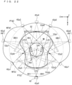
- Fig. 13 is a view illustrating an example of the X-ray tomography.
- the X-ray tomography in Fig. 13 is the CT imaging in which the X-ray generator 42 and the X-ray detector 52 are turned by 360° around the subject M1.
- the imaging region ROI and the tomographic layer of interest LOI in the CT imaging are the same as the CT imaging illustrated in Fig. 9 .
- the X-ray generator 42 is turned from a position 42p0 on the right side of the head to a position 42p4 on the left side of the head through a position 42p1 to a position 42p3 on a rear side of the head.
- the X-ray generator 42 passes from the position 42p4 while turning from the position 42p5 to the position 42p7 on the front side of the head, and returns again to the position 42p0.
- the X-ray detector 52 is turned from the position 52p0 on the left side of the head to the position 52p4 on the right side of the head through the position 52p1 to the position 52p3 on the front side of the head.
- the X-ray detector 52 passes from the position 52p4 while turning from the position 52p5 to the position 52p7 on the front side of the head, and returns again to the position 52p0.
- the normal imaging trajectory NT42 of the X-ray generator 42 and the normal imaging trajectory NT52 of the X-ray detector 52 are matched with a circumference having a predetermined radius centered on the center point CP1 of the imaging region ROI.
- the X-ray generator 42 confronts the tomographic layer of interest LOI twice.
- the first time is when the X-ray generator 42 is located at the position 42p2 (when the projection angle is 90°), and the second time is when the X-ray generator 42 is located at the position 42p6 (when the projection angle is 270°).
- the dose setting unit 308 generates the dose control data for operating the X-ray generation controller 810 or the turning controller 802 such that the unit time dose increases when the X-ray generator 42 passes through the positions 42p2, 42p6.
- Fig. 14 is a view illustrating the graph G10 of the X-ray intensity corresponding to the projection angle in the CT imaging of Fig. 13 .
- a horizontal axis indicates the projection angle
- a vertical axis indicates the X-ray intensity.
- the X-ray intensity is increased from I0 to I1 until the projection angle reaches 90° after passing through about 45°, and the X-ray intensity is decreased from I1 to I0 until the projection angle reaches 180° after passing through 90°.
- the X-ray intensity is increased from I0 to I1 until the projection angle reaches 270° after passing through 180°, and the X-ray intensity is decreased from I1 to I0 until the projection angle reaches 360° after passing through 270°.
- Fig. 15 is a view illustrating the graph G12 of the turning velocity corresponding to the projection angle in the CT imaging of Fig. 13 .
- the horizontal axis indicates the projection angle
- the vertical axis indicates the turning velocity (angular velocity).
- the turning velocity is set to V0 in the period in which the X-ray generator 42 does not confront the tomographic layer of interest LOI
- the turning velocity is set to V1 larger than I0 in the period in which the X-ray generator 42 confronts the tomographic layer of interest LOI.
- the turning velocity is increased from V0 to V1 until the projection angle reaches 90° after passing through about 45°, and the turning velocity is decreased from V1 to V0 until the projection angle reaches 180° after passing through 90°.
- the turning velocity is increased from V0 to V1 until the projection angle reaches 270° after passing through 180°, and the turning velocity is decreased from V1 to V0 until the projection angle reaches 360° after passing through 270°.
- the unit time dose in the period in which the X-ray generator 42 confronts the tomographic layer of interest LOI can be set larger than the unit time dose in the period in which the X-ray generator 42 does not confront the tomographic layer of interest LOI. Consequently, the resolution of the X-ray projection image obtained in the confronting state can be improved. Thus, the tomographic layer of interest LOI suitable for the image diagnosis can be acquired.
- the unit time dose is increased while limiting to a part of the projection angle, so that the X-ray exposure dose of the subject M1 can be suppressed.
- Fig. 16 is a view illustrating an example of the X-ray tomography.
- the X-ray tomography in Fig. 16 is the CT imaging in which the X-ray generator 42 and the X-ray detector 52 are turned by 180° around the subject M1.
- a portion including a right molar in the jaw of the subject M1 is set to the imaging region ROI, and a region extending linearly along a direction parallel to the tangential line of a part of the dental arch DA1 included in the imaging region ROI is set to the tomographic layer of interest LOI.
- the X-ray generator 42 is turned from the position 42p0 on the right rear side of the head of the subject M1 to the position 42p4 on the left rear side of the head through the positions 42p1 to 42p3 on the left side of the head.
- the X-ray detector 52 turns from the position 52p0 on the front left side of the head of the subject M1 to the position 52p4 on the rear right side of the head through the positions 52p1 to 52p3 on the right side of the head.
- the state occurs in which a part or a whole of the X-ray beam BX1 passes through a cervical spine that is a high X-ray absorption site HA1 while the X-ray generator 42 turns.
- the X-ray generator 42 passes through the position 42p1
- the X-ray beam BX1 passes through the high X-ray absorption site HA1.
- the dose setting unit 308 may generate the dose control data for making the unit time dose when the high X-ray absorption site HA1 exists on a path of the X-ray beam BX1 larger than the unit time dose when the high X-ray absorption site HA1 does not exist.
- Fig. 17 is a view illustrating a graph G14 of the X-ray intensity in the CT imaging of Fig. 16 .
- the dose setting unit 308 may create the dose control data for changing the X-ray intensity according to the projection angle as illustrated by the graph G14.
- the graph G14 is obtained by adding a graph G10a to the graph G10.
- the graph G10 is a curve indicating the X-ray intensity when the unit time dose is increased in the period in which the X-ray generator 42 confronts the tomographic layer of interest LOI.
- the X-ray intensity is set to I0 at the projection angle at which the X-ray generator 42 does not confront the tomographic layer of interest LOI
- the X-ray intensity is set to I1 (> I0) at the projection angle (90°) at which the X-ray generator 42 confronts the tomographic layer of interest LOI.
- the graph G10a is a curve indicating the amount of X-ray intensity increasing the unit time dose in order to reduce the influence of the high X-ray absorption site HA1.
- the increase in the X-ray intensity is started from a projection angle ⁇ 1 (in this case, 0° ⁇ ⁇ 1 ⁇ 45°) at which the X-ray beam BX1 starts to overlap the high X-ray absorption site HA1.
- the X-ray intensity is increased by I3 at a projection angle ⁇ 2 (in this case, 45° ⁇ ⁇ 2 ⁇ 90°) at which the overlap between the X-ray beam BX1 and the high X-ray absorption site HA1 becomes the maximum. Subsequently, the X-ray intensity is gradually decreased to a projection angle ⁇ 3 ( ⁇ 2 ⁇ ⁇ 3 ⁇ 90°) at which the overlap between the X-ray beam BX1 and the high X-ray absorption site HA1 disappears.
- ⁇ 2 in this case, 45° ⁇ ⁇ 2 ⁇ 90°
- the X-ray intensity increases in both of the graph G10 and the graph 10a until the projection angle becomes ⁇ 2 after passing through 45°. For this reason, in the graph G14, the X-ray intensity starts to increase from I0 when the projection angle is ⁇ 1, and the X-ray intensity becomes 14 at the projection angle ⁇ 2.
- the X-ray intensity 14 is larger than the X-ray intensity I1 in the period in which the X-ray generator 42 confronts the tomographic layer of interest LOI.
- the dose setting unit 308 generates the dose control data for changing the X-ray intensity as indicated by the graph G14, whereby the resolution of the X-ray projection image can be improved when the X-ray generator 42 confronts the tomographic layer of interest LOI, and the influence of the high X-ray absorption site HA1 can be reduced.
- position information about the high X-ray absorption site HA1 may previously be stored in the storage 31.
- the dose setting unit 308 can preferably read the position information about the high X-ray absorption site HA1 corresponding to a physical feature of the subject M1. That is, by previously preparing the positional information about the high X-ray absorption site HA1 in each physical feature of the subject M1, the X-ray tomography can be performed so as to reduce the influence of the high X-ray absorption site HA1 according to the subject M1.
- the operator may designate the position of the high X-ray absorption site HA1.
- the X-ray projection image (transmission image) obtained by previously performing the X-ray tomography of the subject M1 is displayed on the display 32 or the like, and the operator may select the high X-ray absorption site HA1 on the X-ray projection image.
- the highly accurate position information about the high X-ray absorption site HA1 can be acquired according to the individual subject M1.
- the influence of the high X-ray absorption site HA1 can accurately be reduced.
- the unit time dose is set to the maximum when the X-ray generator 42 confronts the tomographic layer of interest LOI.
- the unit time dose may be larger than that in the period in which the X-ray generator 42 confronts the tomographic layer of interest LOI in a part of the period in which the X-ray generator does not confront the tomographic layer of interest LOI.
- the unit time dose in the period in which the X-ray generator 42 confronts the tomographic layer of interest LOI may be larger than the unit time dose in at least a part of the period in which the X-ray generator 42 does not confront the tomographic layer of interest LOI.
- Figs. 9 and 13 does not mention the high X-ray absorption site HA1 for the sake of easy understanding. However, also in the examples of Figs. 9 and 13 , the influence of the high X-ray absorption site HA1 may be reduced.
- the high X-ray absorption site HA1 (cervical spine) can overlap the path of the X-ray beam BX1 at the timing when the X-ray generator 42 is located at the position 42p2.
- the unit time X-ray dose is preferably increased at the timing when the X-ray generator 42 is located at the position 42p2.
- the X-ray intensity at the projection angle of 90° may be further increased larger than I1 in the graph G10 of Fig. 11 .
- the turning velocity at the projection angle of 90° may further be decreased lower than V1 in the graph G12 of Fig. 12 .
- the high X-ray absorption site HA1 (cervical spine) can overlap the path of the X-ray beam BX1 at the timing when the X-ray generator 42 is located at the position 42p2 and the timing when the X-ray generator 42 is located at the position 42p6. For this reason, the unit time X dose is preferably increased at these timings.
- Fig. 18 is a view illustrating a relationship between a magnification factor and the resolution in the X-ray projection image.
- Fig. 18 schematically illustrates the X-ray generator 42 and the X-ray detector 52 when viewed from the +Z-side (in -Z-direction view).
- the X-ray beam BX1 spreading in a fan shape is emitted from the X-ray tube of the X-ray generator 42.
- the imaging region ROI is enlarged and projected onto the X-ray detector 52.
- the magnification factor of the X-ray projection image (hereinafter, referred to as a "projection magnification factor") projected onto the X-ray detector 52 is determined by a distance from the X-ray generator 42 to the imaging region ROI and a distance from the imaging region ROI to the X-ray detector 52.
- a projection magnification factor the magnification factor of the X-ray projection image projected onto the X-ray detector 52.
- a focal point of the X-ray beam BX1 emitted from the X-ray generator 42 is not a point strictly, but a focal plane 420 having a certain size.
- An anode (focal plane 420) of the actual X-ray tube is inclined with respect to an X-ray irradiation axis.
- the anode is illustrated so as to be perpendicular to the X-ray irradiation axis.
- an X-ray flux passing through the specific point in the X-ray beam BX1 emitted from the focal plane 420 is projected onto the detection surface of the X-ray detector 52 with constant spread. That is, the X-ray beam BX1 emitted from the focal plane 420 causes blurring on the X-ray projection image.
- the projection magnification factor increases, a degree of blurring also increases, and resultantly the resolution (sharpness) of the X-ray projection image decreases.
- the projection magnification factor is desirably decreased as much as possible.
- the X-ray detector 52 is caused to approach the imaging region ROI as much as possible, or the X-ray generator 42 is moved away from the imaging region ROI as much as possible.
- the X-ray detector 52 when the X-ray detector 52 is caused to approach the imaging region ROI, the X-ray detector 52 may come into contact with the subject M1.
- the X-ray generator 42 When the X-ray generator 42 is moved away from the imaging region ROI, there is a possibility that the X-ray generation unit 40 accommodating the X-ray generator 42 collides with another member (for example, the post 70) of the imaging unit 20 or another member other than the imaging unit 20 disposed in the periphery.
- the imaging trajectory setting unit 306 prevents the X-ray detector 52 from contacting with the subject M1 during the X-ray tomography, and sets the imaging trajectory so as to decrease the projection magnification factor as much as possible while preventing the X-ray generation unit 40 of the X-ray generator 42 from colliding with another member. A specific method for setting the imaging trajectory will be described below.
- Fig. 19 is a view illustrating an example of the X-ray tomography.
- the X-ray tomography in Fig. 19 is the CT imaging in which the X-ray generator 42 and the X-ray detector 52 are turned by 180° around the jaw of the subject M1. At this point, the vicinity of the front teeth of the subject M1 is set to the imaging region ROI, and the tomographic layer of interest LOI is set to a linear region along the dental arch DA1.
- the X-ray generator 42 is turned by 180° from a position 42p0 on the right side of the head of the subject M1 to a position 42p4 on the left side of the head after passing through a rear side of the head.
- the X-ray detector 52 passes through a front side of the head from a position 52p0 on the left side of the head of the subject M1, and is turned by 180° to a position 52p4 on the right side of the head.
- the imaging conditions and the like are matched with the CT imaging of Fig. 9 except that this CT imaging differs from the CT imaging of Fig. 9 in the imaging trajectories of the X-ray generator 42 and the X-ray detector 52.
- each of the X-ray generator 42 and the X-ray detector 52 is rotated at a constant rotation radius around a center point CP1 of the imaging region ROI. That is, in the normal CT imaging, the X-ray generator 42 and the X-ray detector 52 are moved on the normal imaging trajectories NT42, NT52.
- the X-ray generator 42 follows the normal imaging trajectory NT42, and the X-ray detector 52 follows the normal imaging trajectory NT52.
- the imaging trajectory setting unit 306 sets imaging trajectories PT42, PT52 in which the projection magnification factor in the period in which the imaging trajectory setting unit 306 confronts the tomographic layer of interest LOI in the imaging region ROI is smaller than that in the period in which the imaging trajectory setting unit 306 does not confront the tomographic layer of interest LOI. More specifically, when the X-ray generator 42 confronts the tomographic layer of interest LOI, as compared with the non-confrontation, the X-ray generator 42 is moved farther away from the tomographic layer of interest LOI, and the X-ray detector 52 is caused to approach the tomographic layer of interest LOI.
- the imaging trajectories PT42, PT52 are referred to as a magnification factor adjustment imaging trajectory
- the X-ray generator 42 follows the magnification factor adjustment imaging trajectory PT42
- the X-ray detector 52 follows the magnification factor adjustment imaging trajectory PT52.
- the CT imaging with the magnification factor adjustment imaging trajectories PT42, PT52 is referred to as magnification factor adjustment CT imaging.
- each of the positions 42p0 to 42p4 of the X-ray generator 42 is the position of the X-ray generator 42 where the incident angle ANG1 becomes 0°, 45°, 90°, 135°, and 180°. That is, the position where the X-ray generator 42 confronts the tomographic layer of interest LOI (the position where the irradiation axis of the X-ray beam BX1 is incident on the tomographic layer of interest LOI in the confronting manner) becomes the position 42p2.
- the position where the X-ray generator 42 does not confront the tomographic layer of interest LOI (the position where the irradiation axis of the X-ray beam BX1 is not incident on the tomographic layer of interest LOI in the confronting manner) becomes positions 42p0, 42p1, 42p3, 42p4.
- the position 42p2 in the confronting state is compared to the positions 42p0, 42p1, 42p3, 42p4 in the non-confronting state, the position 42p2 is a position farther from the tomographic layer of interest LOI than the other positions 42p0, 42p1, 42p3, 42p4. That is, the position 42p2 is set outside the normal imaging trajectory NT42 of the X-ray generator 42.
- the position 52p2 of the X-ray detector 52 in the confronting state is closer to the tomographic layer of interest LOI than the positions 52p0, 52p1, 52p3, 52p4 in the non-confronting state.
- the position 52p2 is set outside the normal imaging trajectory NT52 of the X-ray detector 52.
- the X-ray generator 42 In the CT imaging, until the X-ray generator 42 reaches the position 42p2 of the confronting state after passing through the position 42p1 where the incident angle ANG1 becomes 45°, the X-ray generator 42 is gradually moved away from the tomographic layer of interest LOI, and the X-ray detector 52 is gradually caused to approach the tomographic layer of interest LOI. Until the X-ray generator 42 reaches the position 42p3 where the incident angle ANG1 becomes 135° from the position 42p2 of the confronting state, the X-ray generator 42 is gradually caused to approach the tomographic layer of interest LOI, and the line X-ray detector 52 is gradually moved away from the tomographic layer of interest LOI.
- the position 42p1 to the position 42p3 are different from those of the normal imaging trajectory NT42, and other positions are matched.
- the position 52p1 to the position 52p3 are different from those of the normal imaging trajectory NT52, and other positions are matched.
- Fig. 20 is a view illustrating a fluctuation in the projection magnification factor corresponding to the projection angle.
- the projection magnification factor is kept constant until the incident angle ANG1 reaches 45°, and the projection magnification factor decreases gradually until the incident angle ANG1 becomes 90° after exceeding 45°.
- the projection magnification factor is minimized when the incident angle ANG1 is 90°.
- the projection magnification factor increases gradually until the incident angle ANG1 reaches 135° after the incident angle ANG1 exceeds 90°, and the projection magnification factor is kept constant after the incident angle ANG1 exceeds 135°.
- the magnification factor decreased in the confronting state when the state in which the X-ray generator 42 confronts the tomographic layer of interest LOI (when the X-ray generator 42 is located at the position 42p2) and the state in which the X-ray generator 42 does not confront the tomographic layer of interest LOI (for example, when the X-ray generator 42 is located at the positions 42p0, 42p1, 42p3, 42p4) are compared to each other.
- the magnification factor may be minimized only when the incident angle ANG1 is 90°.
- the minimized magnification factor may have a width. That is, the magnification factor may be maintained at the same minimum magnitude for a certain period from the timing at which the incident angle ANG1 is slightly less than 90°, through the timing at which the incident angle ANG1 is exactly 90°, and to the timing at which the incident angle ANG1 slightly exceeds 90°.
- the imaging trajectory setting unit 306 sets the imaging trajectories PT42, PT52 of the X-ray generator 42 and the X-ray detector 52.
- the imaging controller 80 moves the X-ray generator 42 and the X-ray detector 52 along the imaging trajectories PT42, PT52 by controlling the operations of the turning drive unit 642 and the XY-direction movement drive unit 644. That is, the imaging controller 80 controls the XY-direction movement drive unit 644 according to the incident angle ANG1 while changing the incident angle ANG1 by controlling the operation of the turning drive unit 642. Consequently, the imaging controller 80 relatively decreases the projection magnification factor in the confronting state when the confronting state and the non-confronting state are compared to each other.
- the turning center axis RA1 that is the turning center of the X-ray generator 42 and the X-ray detector 52. While the X-ray generator 42 moves from the position 42p0 to the position 42p1, and while the X-ray generator 42 moves from the position 42p3 to the position 42p4, the turning center axis RA1 is set to the center point CP1. On the other hand, while the X-ray generator 42 moves from the position 42p1 to the position 42p3, as indicated by an arrow D1 in Fig. 10 , the X-ray generator 42 moves on a circular trajectory in which the X-ray generator 42 moves away from the center point CP1 and returns to the center point CP1.
- the X-ray generator 42 and the X-ray detector 52 can be moved on the imaging trajectories PT42, PT52 by moving the shaft 66 on the trajectory of the turning center axis RA1 in Fig. 10 .
- the shaft 66 is not necessarily matched with the turning center axis RA1.
- the technique described in Japanese Patent Application Laid-Open No. 2007-29168 can also be applied to the present application. That is, while the shaft 66 is rotated, the shaft 66 is moved along a circumference of a predetermined radius centered on the center point CP1 of the imaging region ROI in the XY-plane.
- the X-ray generator 42 and the X-ray detector 52 may be turned around the turning center axis RA1 matched with the center point CP1.
- the turning center axis RA1 is set at a position different from the shaft 66 that is the mechanical turning axis.
- the rotational movement and the movement in the XY-plane of the X-ray generator 42 and the X-ray detector 52 are performed by the rotation about the Z-axis of the shaft 66 of the turning arm 62 and the movement in the XY-plane.
- the setting of the imaging trajectories PT42, PT52 of the X-ray generator 42 and the X-ray detector 52 is equivalent to the setting of the position in the XY-plane of the shaft 66 according to the rotation amount of the shaft 66.
- the description of the movement of the turning center axis RA1 will be further supplemented.
- the turning center axis RA1 moves as the rotation center at any time while the X-ray generator 42 and the X-ray detector 52 move along the magnification factor adjustment imaging trajectories PT42, PT52.
- an incident angle at which the incident angle ANG1 is an intermediate angle between 45° and 90° is set to an incident angle ANGla
- an incident angle at which the incident angle ANG1 is 90° is set to an incident angle ANG1b.
- the center axis X-ray CBX1 at the incident angle ANGla is set to a center axis X-ray CBX1A (not illustrated), and the center axis X-ray CBX1 at the incident angle ANGlb is set to a center axis X-ray CBX1B (not illustrated).
- the position of the turning center axis RA1 at the incident angle ANGla takes the position of, for example, RAla in Fig. 10
- the position of the turning center axis RA1 at the incident angle ANGlb takes the position of, for example, RAlb in Fig. 10 .
- the center axis X-ray CBX1 at the incident angle ANGla is a center axis X-ray CBXla matched with the center axis X-ray CBX1A in an incident angle manner
- the center axis X-ray CBX1 at the incident angle ANGlb is a center axis X-ray CBXlb matched with the center axis X-ray CBX1B in the incident angle manner.
- the incident angle is caused to correspond to the incident angle in the normal CT imaging in which the turning center is fixed to one point, and the approach and movement away of the X-ray generator 42 and the X-ray detector 52 are changed with respect to the imaging region during the imaging, which allows the magnification factor adjustment CT imaging to be performed.
- the position RAlb of the turning center axis RA1 at the incident angle of 90° is located at a peak separated from the center point CP1.
- the degree of separation of the position RAla from the center point CP1 is equal to the degree between the position RA10 and the position RA1b. That is, although the position RAla is separated farther from the center point CP1 than the position RA10, the degree of the position RAla is not as large as that of the position RA1b.
- the position of the turning center axis RA1 moves on the axial line of the center axis X-ray CBX1 at each timing at which the incident angle changes.
- the position of the turning center axis RA1 gradually changes such that a degree of separation of the turning center axis RA1 from the center point CP1 peaks while the center axis X-ray CBX1 is incident on the tomographic layer of interest LOI in the confronting manner.
- the degree of separation is maintained so as to be maximized not only in the state in which the center axis X-ray CBX1 is incident on the tomographic layer of interest LOI in the confronting manner, but also in the period of good incident angles close to the confronting state.
- the projection magnification factor is decreased when the X-ray generator 42 confronts the tomographic layer of interest LOI, so that the blurring caused by the size of the focal plane 420 can be reduced on the X-ray projection image when the tomographic layer of interest LOI is projected from the front surface. That is, the X-ray projection image can be acquired with high resolution when the tomographic layer of interest LOI is projected from the front surface.
- the image quality of the X-ray tomographic image generated with respect to the tomographic layer of interest LOI by the image processor 310 can be improved.
- the X-ray detector 52 is caused to approach the tomographic layer of interest LOI by limiting to a part of the entire turning range in which the X-ray generator 42 and the X-ray detector 52 are turned, which prevents the X-ray detector 52 from contacting with the subject M1.
- the X-ray generator 42 is moved away from the tomographic layer of interest LOI by limiting to a part of the entire turning range, so that the X-ray generator 42 or the X-ray generation unit 40 accommodating the X-ray generator 42 and one end of the turning arm 62 supporting the X-ray generation unit 40 can be prevented from colliding with another member (such as the post 70).
- the X-ray generation controller 810 controls the operation of the X-ray regulating unit 44 according to the movement of the X-ray generator 42 away from the tomographic layer of interest LOI during the turning, so that the emission range of the X-ray beam BX1 (a spread angle (fan angle) about the Z-axis of the X-ray beam BX1) may be decreased. Consequently, the range wider than the imaging region ROI can be prevented from being irradiated with the X-ray beam BX1, so that an X-ray exposure dose of the subject M1 can be reduced.
- the setting of the imaging region ROI is received such that the imaging region ROI includes at least a part of the dental arch DA1, and the tomographic layer of interest LOI may be set along a part of the dental arch DA1 set in the imaging region ROI. Consequently, because the X-ray tomographic image along the dental arch DA1 can be acquired, the X-ray tomographic image suitable for the dental diagnosis can be acquired.
- the dental arch DA1 is unevenly distributed in front of the head of the subject M1, and extends along a front edge of the head.
- the setting of the tomographic layer of interest LOI along the dental arch can cause the X-ray detector 52 to approach the head when the X-ray generator confronts the tomographic layer of interest LOI.
- the high-resolution X-ray tomographic image can easily be acquired.
- the imaging trajectory setting unit 306 determines the imaging trajectories PT42, PT52, and the dose setting unit 308 sets the unit time dose of the X-ray with which the subject M1 is irradiated during the X-ray tomography. That is, the dose setting unit 308 generates the dose control data for operating the imaging controller 80 such that the unit time dose in the period in which the X-ray generator 42 confronts the tomographic layer of interest LOI is larger than the unit time dose in the period in which the X-ray generator 42 does not confront the tomographic layer of interest LOI.
- the dose setting unit 308 may generate the dose control data that causes the X-ray generation controller 810 to change the X-ray intensity in Fig. 11 .
- the dose setting unit 308 may generate the dose control data that causes the turning controller 802 to change the turning velocity in Fig. 12 .
- Fig. 21 is a view illustrating an example of the X-ray tomography.
- the X-ray tomography in Fig. 21 is the CT imaging, in which the vicinity of the right molar in the jaw is set to the imaging region ROI and a part of the dental arch DA1 is included in the imaging region ROI.
- the tomographic layer of interest LOI is the region extending linearly along the tangential line of a part of the dental arch DA1 included in the imaging region ROI.
- the X-ray generator 42 is turned by 360° from the position 42p0 at the right rear side of the head of the subject M1 to the position 42p0 after passing through each of the positions 42p1 to 42p7.
- the X-ray detector 52 is turned by 360° from the position 52p0 on the left front side of the head of the subject M1 to the position 52p0 after passing through each of the positions 52p1 to 52p7. That is, in the CT imaging, the imaging conditions and the like are matched with those in the CT imaging of Fig. 13 except for the imaging trajectory.
- the nose of the head is expressed as 12 o'clock
- the back of the head is expressed as 6 o'clock
- a right ear is expressed as 3 o'clock
- a left ear is expressed as 9 o'clock.
- the center axis X-ray CBX1 confronts the tomographic layer of interest LOI while being orthogonal to the tomographic layer of interest LOI when the subject M1 is irradiated with the X-ray beam BX1 from the right side of the subject M1 (specifically, between 12 o'clock and 3 o'clock, and the right side when the entire head is roughly divided into the left and the right) (when the X-ray generator 42 passes through the position 42p2 and the X-ray detector 52 passes through the position 52p2), and when the subject M1 is irradiated with the X-ray beam BX1 from the left side of the subject M1 (specifically, between 6 o'clock and 9 o'clock, and the left side when the entire head is roughly divided into the left and the right) (when the X-ray generator 42 passes through the position 42p6 and the X-ray detector 52 passes through the position 52p6).
- the X-ray generator 42 In the CT imaging, when the X-ray generator 42 confronts the tomographic layer of interest LOI, the X-ray generator 42 passes through the positions 42p2, 42p6.
- the positions 42p2, 42p6 are positions moved farther away from the tomographic layer of interest LOI than the position (for example, the positions 42p0, 42p1, 42p3 to 42p5, 42p7) of the X-ray generator 42 in the period in which the X-ray generator 42 does not confront the tomographic layer of interest LOI.
- the X-ray detector 52 passes through the positions 52p2, 52p6.
- the positions 52p2, 52p6 are positions moved farther away from the tomographic layer of interest LOI than the position (for example, the positions 52p0, 52p1, 52p3 to 52p5, 52p7) of the X-ray detector 52 in the period in which the X-ray generator 42 does not confront the tomographic layer of interest LOI.
- the projection magnification factor in the period in which the X-ray generator 42 confronts the tomographic layer of interest LOI is smaller than the projection magnification factor in the period in which the X-ray generator 42 does not confront the tomographic layer of interest LOI.
- the confronting state when the X-ray generator 42 passes through the position 42p2 is set to a first confronting state
- the confronting state when the X-ray generator 42 passes through the position 42p6 is set to a second confronting state.
- the position 52p2 of the X-ray detector 52 in the first confronting state is closer to the tomographic layer of interest LOI than the position 52p6 of the X-ray detector 52 in the second confronting state.
- the X-ray detector 52 can be caused to approach the imaging region ROI as compared to the case of the irradiation from the right side (between 12 o'clock and 3 o'clock) when the subject M1 is irradiated with the X-ray beam BX1 from the left side (between 6 o'clock and 9 o'clock) of the subject M1.
- the imaging trajectories PT42, PT52 can be corrected when another mechanical element interferes with the turning of the X-ray generator 42 and the X-ray detector 52.
- the imaging trajectories PT42, PT52 can appropriately be corrected so as to avoid the post 70.
- the imaging trajectory setting unit 306 determines the imaging trajectories PT42, PT52, and the dose setting unit 308 sets the dose with which the subject M1 is irradiated during the X-ray tomography. That is, the dose setting unit 308 generates the dose control data for operating the imaging controller 80 such that the unit time dose in the period in which the X-ray generator 42 confronts the tomographic layer of interest LOI is larger than the unit time dose in the period in which the X-ray generator 42 does not confront the tomographic layer of interest LOI.
- the dose setting unit 308 may generate the dose control data that causes the X-ray generation controller 810 to change the X-ray intensity in Fig. 14 .
- the dose setting unit 308 may generate the dose control data that causes the turning movement drive controller 80D to change the turning velocity in Fig. 15 .
- the tomographic layer of interest LOI set in the imaging region ROI is not limited to one.
- Fig. 22 is a view illustrating an example of the X-ray tomography.
- the X-ray tomography in Fig. 22 is the CT imaging, in which the entire jaw of the subject M1 is set to the imaging region ROI and two tomographic layers of interest LOI1, LOI2 are set inside the imaging region ROI. At this point, the tomographic layers of interest LOI1, LOI2 are set to the left temporomandibular joint and the right temporomandibular joint, respectively.
- the X-ray generator 42 is turned by 360° from the position 42p0 in front of the head of the subject M1 to the position 42p0 after passing through the positions 42p1 to 42p7.
- the X-ray detector 52 is turned by 360° from the position 52p0 on the rear side of the head of the subject M1 to the position 52p0 after passing through the positions 52p1 to 52p7.
- the position 42p2 through which the X-ray generator 42 passes is farther from the tomographic layer of interest LOI1 as compared with the position (for example, positions 42p0, 42p1, 42p3 to 42p5, 42p7) in the period in which the X-ray generator 42 does not confront the tomographic layer of interest LOI1.
- the position 52p2 through which the X-ray detector 52 passes is closer to the tomographic layer of interest LOI1 than the position (for example, positions 52p0, 52p1, 52p3 to 52p5, 52p7) in the period in which the X-ray generator 42 does not confront the tomographic layer of interest LOI1.
- the projection magnification factor in the period in which the X-ray generator 42 confronts the tomographic layer of interest LOI1 can be decreased relatively smaller than the projection magnification factor in the period in which the X-ray generator 42 does not confront the tomographic layer of interest LOI1.
- the position 42p6 through which the X-ray generator 42 passes when the X-ray generator 42 confronts a tomographic layer of interest LOI2 is farther from the tomographic layer of interest LOI2 than the positions (for example, the positions 42p0, 42p1, 42p3 to 42p5, 42p7) in the non-confronting state.
- the position 52p6 through which the X-ray detector 52 passes is closer to the tomographic layer of interest LOI2 than the position (for example, positions 52p0, 52p1, p3 to 52p5, 52p7) in the non-confronting state. Consequently, the projection magnification factor can be decreased when the X-ray generator 42 confronts the tomographic layer of interest LOI2.
- the position 42p6 is the position when the X-ray generator 42 does not confront the tomographic layer of interest LOI1. It is also assumed that the position 42p2 is closer to the tomographic layer of interest LOI1 than the position 42p6. That is, the position 42p2 through which the X-ray generator 42 passes when confronting the tomographic layer of interest LOI1 is not necessarily farther from the tomographic layer of interest LOI1 than all the positions through which the X-ray generator 42 passes when the X-ray generator 42 does not confront the tomographic layer of interest LOI1.
- the position 42p2 may be farther from the tomographic layer of interest LOI1 than at least a part of all the positions through which the X-ray generator 42 passes when the X-ray generator 42 does not confront the tomographic layer of interest LOI1.
- the position 52p6 is the position of the X-ray detector 52 when the X-ray generator 42 does not confront the tomographic layer of interest LOI, but it is assumed that the position 52p6 is located closer to the tomographic layer of interest LOI than the position 52p2. That is, the position 52p2 may be closer to the tomographic layer of interest LOI1 than at least a part of all the positions through which the X-ray detector 52 passes when the X-ray generator 42 does not confront the tomographic layer of interest LOI1.
- the dose setting unit 308 generates the dose control data such that the unit time dose in the period in which the X-ray generator 42 confronts the tomographic layer of interest LOI is larger than the unit time dose in the period in which the X-ray generator 42 does not confront the tomographic layer of interest LOI.
- the dose setting unit 308 generates the dose control data such that the unit time dose in the period in which the X-ray generator 42 confronts the tomographic layer of interest LOI2 is larger than the unit time dose in the period in which the X-ray generator 42 does not confront the tomographic layer of interest LOI2.
- Fig. 23 is a view illustrating the graph G10 of the X-ray intensity corresponding to the projection angle in the CT imaging of Fig. 22 .
- the horizontal axis indicates the projection angle
- the vertical axis indicates the X-ray intensity.
- the X-ray intensity is set to I1 in the period in which the X-ray generator 42 confronts the tomographic layer of interest LOI1 (at the projection angle of ⁇ 1) and the period in which the X-ray generator 42 confronts the tomographic layer of interest LOI2 (at the projection angle of ⁇ 2), and the X-ray intensity is set to I0 smaller than I1 in the period in which the X-ray generator 42 does not confront the tomographic layer of interest LOI1 and the tomographic layer of interest LOI2.
- Fig. 24 is a view illustrating the graph G12 of the turning velocity corresponding to the projection angle in the CT imaging of Fig. 22 .
- the horizontal axis indicates the projection angle
- the vertical axis indicates the turning velocity.
- the turning velocity is set to V1 in the period in which the X-ray generator 42 confronts the tomographic layer of interest LOI1 (at the projection angle of ⁇ 1) and the period in which the X-ray generator 42 confronts the tomographic layer of interest LOI2 (at the projection angle of ⁇ 2), and the turning velocity is set to V0 smaller than V1 in the period in which the X-ray generator 42 does not confront the tomographic layer of interest LOI1 and the tomographic layer of interest LOI2.
- the projection magnification factor is reduced and the unit time dose is increased.
- the projection magnification factor may be decreased and the unit time dose may be increased.
- the projection magnification factor is decreased and the unit time dose is increased.
- the projection magnification factor may be decreased and the unit time dose may be increased.
- the support 60 is elevated and lowered with respect to the head MH by the relative movement, which allows the X-ray irradiation location to be changed in the Z-axis direction.
- the plurality of imaging regions located at different height positions can continuously be imaged such that one of the tooth rows of the upper jaw and the lower jaw is continuously imaged after the other is imaged.
- different regions of the dental arch may be set to the imaging target in each height position such that a front-tooth region is set in the upper jaw and a molar region is set in the lower jaw.
- Fig. 25 is a view illustrating an example of the X-ray tomography.
- the X-ray tomography in Fig. 25 is tomosynthesis imaging in which the X-ray generator 42 and the X-ray detector 52 are turned by an angle less than 180° around the head of the subject M1.
- the turning angle may be set to 90° or 60°. Any angle less than 180° may be set by the operation, and any angle between 90° and 60° may be set by the operation.
- the tomosynthesis imaging as illustrated in Fig.
- the X-ray projection image is acquired by rotating the X-ray generator 42 and the X-ray detector 52 to the left and right by a required angle around the incident angle ANG1 at which the X-ray generator 42 confronts the tomographic layer of interest LOI to be observed by an observer.
- an X-ray tomographic images having relatively high quality can be acquired by reconstruction with respect to the tomographic layer of interest LOI. Since the X-ray irradiation less than only 180° is performed, the tomosynthesis imaging has an advantage that an imaging time can be shortened while the X-ray exposure dose of the subject M1 is reduced as compared with the CT imaging.
- the imaging region ROI is set in the vicinity of the front teeth of the jaw of the subject M1, and the tomographic layer of interest LOI is set along the portion of the dental arch DA1 included in the imaging region ROI.
- the X-ray generator 42 is turned from the position 42p0 on the right rear side of the subject M1 to the position 42p2 on the left rear side
- the X-ray detector 52 is turned from the position 52p0 on the right front side of the subject M1 to the position 52p2 on the left front side.
- the imaging trajectories of the X-ray generator 42 and the X-ray detector 52 are set such that the X-ray generator 42 passes through the position 42p1 and the X-ray detector 52 passes through the position 52p1.
- the position 42p1 of the X-ray generator 42 is farther from the tomographic layer of interest LOI than the position (for example, the positions 42p0, 42p2) of the X-ray generator 42 when the X-ray generator 42 does not confront the tomographic layer of interest LOI.
- the position 52p1 is closer to the tomographic layer of interest LOI than the position (for example, the positions 52p0, 52p2) of the X-ray detector 52 when the X-ray generator 42 does not confront the tomographic layer of interest LOI.
- the setting of the imaging trajectory in this manner decreases the projection magnification factor during the confrontation, so that the high-quality X-ray tomographic image can be generated with respect to the tomographic layer of interest LOI.
- the dose setting unit 308 In performing the tomosynthesis imaging in Fig. 25 , the dose setting unit 308 generates the dose control data for operating the imaging controller 80 such that the unit time dose is relatively increased as compared with the case where the X-ray generator 42 confronts the tomographic layer of interest LOI and the case where the X-ray generator 42 does not confront the tomographic layer of interest LOI.
- the X-ray intensity when the X-ray generator 42 passes through the position 42p1 where the X-ray generator 42 confronts the tomographic layer of interest LOI is preferably increased larger than the X-ray intensity at the position (for example, the positions 42p0, 42p2) where the X-ray generator 42 does not confront the tomographic layer of interest LOI.
- the turning velocity when the X-ray generator 42 is located the position 42p1 where the X-ray generator 42 confronts the tomographic layer of interest LOI is preferably decreased smaller than the turning velocity at the position (for example, the positions 42p0, 42p2) where the X-ray generator 42 does not confront the tomographic layer of interest LOI.
- Fig. 26 is a flowchart illustrating the operation of the X-ray tomography apparatus 10. In the following description, it is assumed that positioning of the subject M1 in the imaging unit 20 is already completed.
- the information processor 30 causes the display 32 to display the designation image for designating the tomographic layer of interest LOI or the imaging region ROI (step S101).
- the designation image is a schematic diagram IL1 in which the site of interest is drawn, or a transmission image (such as a panoramic X-ray image IL2 and a transmission image in which the X-ray tomography is performed in the two directions) obtained by the X-ray tomography of the subject M1.
- the information processor 30 receives an operation to designate a skeleton size (step S102). For example, when the operator inputs the physical characteristics (such as the gender, the age, the height, and the weight) of the subject M1, the information processor 30 acquires the skeleton size corresponding to the input physical characteristics from a predetermined database. In each size, a standard size may be set from statistical data. The acquired skeleton size is used to approximately match the position of the imaging target site of the subject M1 disposed in the imaging unit 20 with the position of the imaging target site in the designation image.
- a skeleton size For example, when the operator inputs the physical characteristics (such as the gender, the age, the height, and the weight) of the subject M1, the information processor 30 acquires the skeleton size corresponding to the input physical characteristics from a predetermined database. In each size, a standard size may be set from statistical data. The acquired skeleton size is used to approximately match the position of the imaging target site of the subject M1 disposed in the imaging unit 20 with the position of the imaging target
- step S102 may be skipped.
- the information processor 30 may re-display the designation image matched with the designated skeleton size on the display 32. For example, the schematic diagram IL1 for each physical characteristic is previously prepared, and the schematic diagram IL1 corresponding to the specified physical characteristic may be displayed.
- the information processor 30 receives an operation to designate the tomographic layer of interest LOI or the imaging region ROI (step S103).
- the operation to designate the tomographic layer of interest LOI or the imaging region ROI is described with reference to Figs. 4 to 8 .
- each of the tomographic layer of interest LOI and the imaging region ROI may individually be designated.
- the tomographic layer of interest LOI may automatically be set according to the designation of the imaging region ROI.
- the imaging region ROI may automatically be set according to the designation of the tomographic layer of interest LOI.
- the tomographic layer-of-interest setting unit 304 sets the position, the size, and the direction of the tomographic layer of interest LOI based on the designation operation received in step S103 (step S104).
- the imaging trajectory setting unit 306 determines the imaging trajectories of the X-ray generator 42 and the X-ray detector 52 when the X-ray tomography is performed (step S105).
- the imaging trajectory setting unit 306 determines the imaging trajectories PT42, PT52 of the X-ray generator 42 and the X-ray detector 52 based on the tomographic layer of interest LOI set in step S104. Specifically, as described above with reference to Figs.
- the imaging trajectory setting unit 306 determines the imaging trajectories PT42, PT52 such that the projection magnification factor when the X-ray generator 42 confronts the tomographic layer of interest LOI is smaller than the projection magnification factor when the X-ray generator 42 does not confront the tomographic layer of interest LOI.
- the imaging trajectory setting unit 306 determines the normal imaging trajectories NT42, NT52 as described above with reference to Figs. 9 , 13 , and 16 .
- the operator can select whether the projection magnification factor is changed in performing the X-ray tomography. That is, a selection screen selecting necessity of the change of the projection magnification factor is displayed on the display 32, and the operator may perform operation input through the operation unit 34 according to the selection screen.
- the dose setting unit 308 sets the dose with which the subject M1 is irradiated when the X-ray tomography is performed (step S106). Specifically, as described with reference to Figs. 9 to 17 , the dose setting unit 308 generates the dose control data for operating the imaging controller 80 such that the unit time dose in the period in which the X-ray generator 42 confronts the tomographic layer of interest LOI is larger than the unit time dose in the period in which the X-ray generator 42 does not confront the tomographic layer of interest LOI.
- the dose setting unit 308 may generate the dose control data for operating the X-ray generation controller 810.
- the dose setting unit 308 may generate the dose control data for operating the turning movement drive controller 80D.
- the dose setting unit 308 may change the unit time dose corresponding to the projection angle in consideration of the high X-ray absorption site HA1.
- the dose setting unit 308 may generate the dose control data for operating the imaging controller 80 so as to increase the unit time dose at the projection angle at which the X-ray beam BX1 passes through the high X-ray absorption site HA1.
- the position information about the high X-ray absorption site HA1 used at this time may correspond to the skeleton size designated in step S102. In this case, the pieces of position information about a plurality of high X-ray absorption sites HA1 according to the physical characteristics of the subject is previously stored in the storage 31, and the position information corresponding to the designated skeleton size may be read out from the storage 31.
- the imaging unit 20 After the setting of the imaging trajectory in step S105 and the setting of the unit time dose in step S106, the imaging unit 20 performs the X-ray tomography (step S107). Specifically, data of the imaging trajectory and the dose control data are sent to the imaging controller 80. Based on the data, the X-ray irradiation with the set unit time dose is performed, and the turning movement drive controller 80D performs the control such that the turning controller 802 controls the operation of the turning drive unit 642, and such that the XY-direction movement controller 804 controls the operation of the XY-direction movement drive unit 644.
- the imaging unit 20 captures the X-ray projection image of the imaging region ROI projected on the detection surface of the X-ray detector 52 at a predetermined frame rate. The captured X-ray projection image is appropriately stored in the storage 31 or the like of the information processor 30.
- the image processor 310 performs reconstruction arithmetic processing on the plurality of X-ray projection images acquired in step S107 (step S108). Specifically, the image processor 310 generates three-dimensional volume data of the imaging region ROI by a filter correction back projection method (FBP method), a superposition integration method, or the like. The image processor 310 generates the X-ray tomographic image representing the tomographic layer of interest LOI based on the three-dimensional volume data. Although being concentrated on and around the tomographic layer of interest LOI, three-dimensional image data having a certain thickness can also be generated in the tomosynthesis imaging, and the X-ray tomographic image representing the tomographic layer of interest LOI can be generated.
- FBP method filter correction back projection method
- the dose setting unit 308 generates the dose control data so as to decrease the unit time dose when the X-ray generator 42 does not confront the tomographic layer of interest LOI.
- the noise is easily generated in the X-ray projection image. This is because the image quality is degraded due to the influence of Poisson noise (shot noise) generated by the low dose.
- the image processor 310 performs the smoothing processing on the X-ray projection image obtained at the projection angle in the non-confronting state.
- the X-ray tomographic image is generated for the tomographic layer of interest LOI
- the X-ray tomographic image is displayed on the display 32 (step S109).
- the smoothing filter used when the image processor 310 smoothes the X-ray projection image will be described below.
- Fig. 27 is a view illustrating the state in which the tomographic layer of interest LOI is irradiated with the X-ray.
- Fig. 28 is a view illustrating the change in the X-ray intensity when the X-ray tomography is performed on the tomographic layer of interest LOI.
- the tomographic layer of interest LOI that extends in parallel to the X-axis and has a predetermined thickness in the Y-axis direction.
- the center of the tomographic layer of interest LOI is set to an origin (0, 0) of an XY-coordinate system. It is assumed that the X-ray generator 42 turns such that the center axis X-ray CBX1 of the X-ray beam BX1 always passes through the origin.
- Fig. 27 it is assumed that the tomographic layer of interest LOI that extends in parallel to the X-axis and has a predetermined thickness in the Y-axis direction.
- the center of the tomographic layer of interest LOI is set to an origin (0, 0) of an XY-coordinate system. It is assumed that the X-ray generator 42 turns such that the center axis X-ray CBX1 of the X-ray beam BX1 always passes through the origin.
- the direction of the center axis X-ray CBX1 at the beginning of the X-ray tomography is set to the +X-direction
- the rotation angle of the center axis X-ray CBX1 from the X-axis is set to the projection angle ⁇ .
- X-ray irradiation starts with the relatively low X-ray intensity I0 from the projection angle of 0°, and the X-ray intensity is increased from the near side on which the projection angle becomes 90° - ⁇ .
- the X-ray irradiation is performed with relatively high X-ray intensity I1.
- the X-ray intensity is maintained at I1 at the projection angle of 90° and around 90°.
- the X-ray intensity is decreased from the near side on which the projection angle becomes 90° + ⁇ , and the X-ray intensity is decreased from around the projection angle that passes through 90° + ⁇ , and decreased to the relatively low X-ray intensity I0.
- the X-ray intensity is maintained at I0 until the projection angle becomes 180°.
- Fig. 29 is a view illustrating a spatial frequency distribution of the X-ray projection image projected at the projection angle ⁇ .
- a Fourier coefficient at the position of a straight line LL2 is obtained as illustrated in Fig. 29 .
- the angle between the straight line LL2 and the horizontal axis ( ⁇ axis) is ⁇ - 90°.
- the Fourier coefficient of a high-frequency component is acquired while attenuated more than the Fourier coefficient of a low-frequency component.
- Fig. 30 is a view conceptually illustrating the spatial frequency distribution of X-ray projection data for 180°.
- the spatial frequency distribution in which the Fourier coefficient of the high frequency component is attenuated with respect to the original image can be obtained by acquiring X-ray projection data for 180°.
- the original image can be reconstructed by performing inverse Fourier transform or the like on the spatial frequency distribution.
- the Gaussian filter H is given by the following equation.
- the multiplication of the spatial frequency distribution of projection data and the Gaussian filter H means the obtainment of a composition product (h ⁇ f) of a distribution f obtained by the inverse Fourier transform and h that is the inverse Fourier transform of H.
- the inverse Fourier transform h and the composition product (h ⁇ f) of H are given by the following equations.
- the obtainment of the composition product of the distribution f and the inverse Fourier transform h is equivalent to the blurring of the distribution f in the Y-direction.
- the blurring in the Y-direction means performing addition in the Y-direction. That is, the blurring in the Y-direction is equivalent to calculation of the X-ray tomographic image having a tomographic thickness 2r or 4r.
- Fig. 31 is a view illustrating multiplication of the spatial frequency distribution of the projection data in Fig. 30 and the Gaussian filter H. As illustrated in Fig. 31 , the shape is attenuated in an ⁇ -direction by multiplying the spatial frequency distribution of the projection data in Fig. 30 by the Gaussian filter H.
- the image in which the X-ray tomography obtaining the spatial frequency distribution in Fig. 31 and the inverse Fourier transform are performed is an image in which the distribution f obtained by CT reconstruction is blurred by the inverse Fourier transform h of the equation (2), namely, an image of the tomographic layer parallel to the X-axis.
- the image processing is performed on the obtained X-ray projection image.
- the smoothing processing (blurring processing) in the rotational direction is performed on the X-ray projection image obtained at the projection angle at which the X-ray intensity is relatively small (10).
- the noise is reduced by the addition because the image quality is degraded due to the influence of Poisson noise (shot noise) generated by the low dose.
- Fig. 32 is a view conceptually illustrating the spatial frequency distribution of all pieces of X-ray projection data when the smoothing processing is performed on the low-dose X-ray projection image.
- the spatial frequency distribution of Fig. 32 as to the spatial frequency distribution corresponding to the projection angle (0° to 90° - ⁇ , 90° + ⁇ to 180°) of relatively low unit time dose, a distribution radius becomes relatively small because the high-frequency component is attenuated by the smoothing processing.
- the spatial frequency distribution corresponding to the projection angle (90° - ⁇ to 90° + ⁇ ) of relatively high unit time dose the distribution radius becomes relatively large.
- the spatial frequency distribution in Fig. 32 includes information necessary for the calculation of the X-ray tomographic image of the tomographic layer of interest LOI having a certain thickness in the Y-axis direction.
- d is the radius of the smoothing filter.
- ⁇ is the thickness of the required tomographic layer of interest LOI
- the length on the + ⁇ -side of the rectangular region RR in the spatial frequency distribution becomes 1/ ⁇ .
- the range of the angle at which the relatively high unit time dose is irradiated is reduced when the thickness ⁇ of the tomographic layer of interest LOI is increased, and the range of the angle at which the relatively higher unit time dose is irradiated is enlarged when the thickness ⁇ of the tomographic layer of interest LOI is decreased.
- a tomographic thickness designation receiving unit 304t that receives the designation of the tomographic thickness (not illustrated) may be provided in the tomographic layer-of-interest setting unit 304.
- an increase and decrease pattern of the unit time dose based on the control of the imaging controller 80 may be set according to the size of the tomographic thickness relating to the designation received by the tomographic thickness designation receiving unit 304t. That is, when the tomographic thickness relating to the designation is relatively large, the imaging controller 80 may relatively reduce the range of the incident angle of the X-ray beam BX1 emitting the relatively high unit time dose. When the tomographic thickness relating to the designation is relatively small, the imaging controller 80 may enlarge the range of the incident angle of the X-ray beam BX1 emitting the relatively high unit time dose.
- the radius of the smoothing may be changed according to the dose change (the change in the smoothing size). Specifically, when the dose is 1/ ⁇ , the radius d of the smoothing filter may be increased larger than 2 ⁇ . When the radius d is excessively increased, the strength of the rectangular region RR is weakened.
- the high X-ray intensity is set to I1 and the low X-ray intensity is set to 10. It is assumed that T ⁇ 0 is the total dose when the X-ray tomography is performed while the X-ray intensity is fixed at I1, and that T ⁇ 1 is the total dose of the X-ray tomography of the embodiment.
- the ratio of TyO and T ⁇ 1 is given by the following equation (5).
- T ⁇ 0 : T ⁇ 1 becomes approximately 4 : 1. That is, when the X-ray tomography is performed while the low dose and the high dose are switched, the total exposure dose can be suppressed to 1/4 as compared with the case where the X-ray tomography is always performed with the high dose.
- An SN ratio is decreased by decreasing the unit time dose. It is conceivable that the SN ratio is improved by adding pixel values by the dose ratio.
- the dose ratio in this case, the ratio of X-ray intensities I0 and I1
- 1/5 1/2d, namely, the radius d may be set to 2.5 when the pixels are continuously considered.
- 1/5 1/(2d + 1), namely, the radius d may be set to 2.
- ⁇ may be set to any value.
- the arithmetic calculation may be performed while ⁇ is set to 5° according to the substantially right angle in the above description with reference to Fig. 10 .
- Fig. 33 is a view illustrating a configuration of an X-ray tomography apparatus 10 according to a first modification.
- a subject holder 72a of the first modification includes a subject chair 74 on which the subject M1 is seated.
- the XY-direction movement drive unit 644 translates the turning arm 62 in the XY plane by moving the shaft 66 in the X axis direction and the Y axis direction.
- the X-ray generator 42 and the X-ray detector 52 move relative to the subject M1 in the X-axis direction and the Y-axis direction.
- the XY-direction movement drive unit 644 is connected to the subject chair 74, and moves the subject chair 74 in the X-axis direction and the Y-axis direction. Consequently, the subject M1 moves relative to the X-ray generator 42 and the X-ray detector 52 of the turning arm 62 in the X-axis direction and the Y-axis direction.
- the subject chair 74 is moved so as to move the subject M1 to an appropriate position during the X-ray tomography. That is, when the X-ray generator 42 confronts the tomographic layer of interest LOI, the portion corresponding to the tomographic layer of interest LOI is moved away from the X-ray generator 42, and caused to approach the X-ray detector 52. Consequently, the projection magnification factor can be decreased in the confronting state.
- the turning drive unit 642 rotates the turning arm 62 to turn the X-ray generator 42 and the X-ray detector 52 around the subject M1.
- the turning drive unit 642 may rotate the subject holder to rotate the subject.
- the imaging unit 20 does not necessarily include the turning arm 62.
- the X-ray generation unit 40 and the X-ray detection unit 50 are attached to a ring-shaped annular member, the X-ray generation unit 40 and the X-ray detection unit 50 may move along the circumferential direction of the annular member.
- a virtual axis passing through the center of the annular member is the turning center axis RA1.
- the turning center axis RA1 extending in the Z-axis direction is set to the vertical direction.
- the turning center axis RA1 may be set to the horizontal direction.
- the projection magnification factor when the X-ray generator 42 confronts the tomographic layer of interest LOI, the projection magnification factor is decreased by moving both the X-ray generator 42 and the X-ray detector 52 with respect to the tomographic layer of interest LOI.
- the projection magnification factor may be decreased by moving only one of the X-ray generator 42 and the X-ray detector 52 with respect to the tomographic layer of interest LOI.
- Fig. 34 is a view illustrating the state in which the projection magnification factor is decreased by moving only the X-ray detector 52. As illustrated in Fig. 34 , the projection magnification factor is decreased by causing only the X-ray detector 52 to approach the imaging region ROI. Consequently, the blurring on the X-ray projection image due to the size of the focal plane 420 can be reduced.
- a movement drive unit (not illustrated) that moves the X-ray detector 52 in the y-direction may be provided in the X-ray detection unit 50.
- the movement drive unit may be constructed with a linear motor type or ball screw type drive unit.
- Fig. 35 is a view illustrating the state in which the projection magnification factor is decreased by moving only the X-ray generator 42.
- the projection magnification factor is decreased by moving only the X-ray generator 42 (focal plane 420) away from the imaging region ROI. Consequently, the blurring on the X-ray projection image due to the size of the focal plane 420 can be reduced.
- the focal plane 420 in Figs. 34 and 35 is equivalent to the focal plane 420 in Fig. 18 .
- a movement drive unit that moves the entire X-ray generation unit 40 including the X-ray generator 42 in the y-direction may be provided in the turning arm 62.
- the turning arm 62 is expandably configured.
- Fig. 36 is a schematic side view illustrating a turning arm 62a according to a modification.
- one end 620 supporting the X-ray generation unit 40 is configured to be accommodated inside a main body 622 of the turning arm 62.
- the turning arm 62a includes a movement drive unit (not illustrated) that moves the one end 620 in the y-direction.
- the movement drive unit accommodates the one end 620 in the main body 622, whereby the turning arm 62 is shortened and the X-ray generator 42 approaches the X-ray detector 52.
- the movement drive unit takes the one end 620 out of the main body 622, whereby the turning arm 62 is extended to separate the X-ray generator 42 from the X-ray detector 52.
- the turning arm 62a of the modification In the turning arm 62a of the modification, the turning arm 62a itself is expandable when the X-ray generation unit 40 is moved. When the turning arm 62a passes through a space that collides with another member during the turning, the collision can be avoided by shortening the turning arm 62a.
- Fig. 37 is a schematic side view illustrating a turning arm 62b according to a modification.
- the turning arm 62b includes a movement drive unit 624 that moves the X-ray generation unit 40 in the y-direction with respect to the turning arm 62.
- the projection magnification factor can be decreased by moving the X-ray generator 42 in the direction in which the X-ray generator 42 is moved away from the subject M1.
- the turning arm 62b by moving the X-ray generation unit 40 in the y-direction, the X-ray generation unit 40 can be prevented from contacting with another member during the turning. Because the turning arm 62b itself is not expandable, it is necessary that the turning arm 62b be turned such that the turning arm 62 does not contact with another member. In this respect, the turning arm 62a in Fig. 37 is more advantageous than the turning arm 62b.
- Fig. 38 is a view illustrating an example of the X-ray tomography.
- Fig. 39 is a view illustrating the graph G10 of the X-ray intensity corresponding to the projection angle in the CT imaging of Fig. 38 .
- the imaging region ROI and the tomographic layer of interest LOI in this CT imaging are matched with the imaging region ROI and the tomographic layer of interest LOI in the CT imaging of Fig. 9 .
- this CT imaging differs from the CT imaging of Fig. 9 in that the position 42p0 of the X-ray generator 42 at the beginning of the X-ray is the position where the X-ray generator 42 confronts the tomographic layer of interest LOI.
- the X-ray intensity is set to relatively large I1 at the projection angle of 0° as illustrated in Fig. 39 .
- the X-ray intensity is set to I0 smaller than I1 in the period in which the X-ray generator 42 does not confront the tomographic layer of interest LOI (for example, the period in which the X-ray generator 42 passes through the positions 42p1 to 42p3).
- the X-ray generator 42 confronts the tomographic layer of interest LOI again at the position 42p4 where the projection angle becomes 180°.
- the X-ray intensity may be increased to I1 until the X-ray generator 42 reaches the position 42p4.
- the change of the unit time dose is performed by the change of the X-ray intensity
- the change of the unit time dose may be performed by the change of the turning velocity.
- Fig. 40 is a view illustrating an example of the X-ray tomography.
- the X-ray tomography in Fig. 40 is an example of the CT imaging called offset scan.
- the X-ray detector 52 is disposed while laterally offset with respect to the center point CP1 of the imaging region ROI such that the irradiation range of the X-ray beam BX1 becomes greater than or equal to a half of the imaging region ROI and less than the whole imaging region ROI.
- the center axis X-ray CBX1 of the X-ray beam BX1 is set at a position displaced from the center point CP1 of the imaging region ROI.
- the turning center of the X-ray beam BX1 during the CT imaging is set to the center point CP1 of the imaging region ROI.
- the CT imaging in which the X-ray projection data of the imaging region ROI is acquired is performed while the X-ray beam BX1 is shifted so as to always pass through the half of the imaging region ROI.
- the X-ray generator 42 is turned from the position 42p0 by 360° about the center point CP1 of the imaging region ROI to acquire the X-ray projection data for 180° with respect to the imaging region ROI.
- the imaging controller 80 controls the turning drive unit 642 and the XY-direction movement drive unit 644 to move the shaft 66 on the circular trajectory indicated by a broken line.
- the unit time dose in the period in which the X-ray generator 42 confronts the tomographic layer of interest LOI may be increased larger than the unit time dose in the period in which the X-ray generator 42 does not confront the tomographic layer of interest LOI.
- the X-ray generator 42 becomes the state in which the center axis X-ray CBX1 of the X-ray beam BX1 emitted from the X-ray generator 42 is orthogonally incident on the tomographic layer of interest LOI, namely, the state in which the X-ray generator 42 confront the tomographic layer of interest LOI at the position 42p0 where the projection angle is 0° and the position 42p2 where the projection angle is 180°.
- the unit time dose is relatively increased at the positions 42p0, 42p2.
Landscapes
- Health & Medical Sciences (AREA)
- Life Sciences & Earth Sciences (AREA)
- Engineering & Computer Science (AREA)
- Medical Informatics (AREA)
- Heart & Thoracic Surgery (AREA)
- Animal Behavior & Ethology (AREA)
- Biophysics (AREA)
- Nuclear Medicine, Radiotherapy & Molecular Imaging (AREA)
- Optics & Photonics (AREA)
- Pathology (AREA)
- Radiology & Medical Imaging (AREA)
- Biomedical Technology (AREA)
- Physics & Mathematics (AREA)
- Molecular Biology (AREA)
- Surgery (AREA)
- High Energy & Nuclear Physics (AREA)
- General Health & Medical Sciences (AREA)
- Public Health (AREA)
- Veterinary Medicine (AREA)
- Dentistry (AREA)
- Oral & Maxillofacial Surgery (AREA)
- Pulmonology (AREA)
- Theoretical Computer Science (AREA)
- Human Computer Interaction (AREA)
- Apparatus For Radiation Diagnosis (AREA)
Claims (12)
- Röntgentomografievorrichtung (10), aufweisend:einen Röntgengenerator (40), der einen Röntgenstrahl emittiert;einen Röntgendetektor (50), der den vom Röntgengenerator (40) emittierten Röntgenstrahl detektiert;einen Träger (60), der den Röntgengenerator (40) und den Röntgendetektor (50) trägt;eine eine interessierende tomografische Schicht einstellende Einheit (304), die eine Position einer interessierenden tomografischen Schicht (LOI) einstellt;eine Drehantriebseinheit (642), die den Röntgengenerator (40) und den Röntgendetektor (50) um zumindest eine Drehzentrumsachse (RA1) in Bezug auf die interessierende tomografische Schicht (LOI) relativ dreht;einen Bildprozessor (310), der ein Röntgentomografiebild, das die interessierende tomografische Schicht (LOI) angibt, erzeugt, indem eine Bildverarbeitung an einem Projektionsbild durchgeführt wird, das basierend auf einem vom Röntgendetektor (50) abgegebenen Ausgangssignal erzeugt wird; undeinen Controller (80), der die Drehantriebseinheit (642) und eine Änderung einer Einheitszeitdosis steuert, die eine Röntgendosis ist, mit der die interessierende tomografische Schicht (LOI) pro Einheitszeit bestrahlt wird,wobei der Controller (80) die Drehantriebseinheit (642) und die Änderung der Einheitszeitdosis so steuert, dass die Einheitszeitdosis in zumindest einem Teil einer Periode, in der eine Zentrumsachse (CBX1) des Röntgenstrahls nicht orthogonal zur interessierenden tomografischen Schicht (LOI) ist, relativ geringer ist als die Einheitszeitdosis in einer Periode, in der die Zentrumsachse (CBX1) des Röntgenstrahls zur interessierenden tomografischen Schicht (LOI) orthogonal ist.
- Röntgentomografievorrichtung (10) nach Anspruch 1, wobeider Träger (60) einen Dreharm (62; 62a; 62b) umfasst, der den Röntgengenerator (40) an einer Endseite trägt, während er den Röntgendetektor (50) an der anderen Endseite trägt, unddie Drehantriebseinheit (642) den Dreharm (62; 62a; 62b) über eine Welle (66) dreht, wobei die Welle (66) mit einer Position zwischen dem Röntgengenerator (40) und dem Röntgendetektor (50) im Dreharm (62; 62a; 62b) verbunden ist.
- Röntgentomografievorrichtung (10) nach Anspruch 1 oder 2, ferner aufweisend eine einen Abbildungsbereich einstellende Einheit (302), die einen Abbildungsbereich einstellt, der mittels des Röntgenstrahls aus einer Vielzahl von Richtungen bestrahlt wird, wodurch eine Vielzahl von Projektionsbildern erfasst wird, wobei die einen Abbildungsbereich einstellende Einheit (302) den Abbildungsbereich basierend auf einer Eingabeoperation zur Bestimmung über eine Bedienungseinheit (34) einstellt.
- Röntgentomografievorrichtung (10) nach Anspruch 3, wobei die eine interessierende tomografische Schicht einstellende Einheit (304) die Position der interessierenden tomografischen Schicht (LOI) gemäß dem durch die einen Abbildungsbereich einstellende Einheit (302) eingestellten Abbildungsbereich einstellt.
- Röntgentomografievorrichtung (10) nach Anspruch 4, wobeidie Bedienungseinheit (34) eine Bestimmung des Abbildungsbereichs empfängt, so dass er einen Teil eines Zahnbogens (DA1) enthält, unddie eine interessierende tomografische Schicht einstellende Einheit (304) die interessierende tomografische Schicht (LOI) entlang dem Teil des Zahnbogens (DA1) einstellt, der im Abbildungsbereich (DA1) enthalten ist.
- Röntgentomografievorrichtung (10) nach einem der Ansprüche 1 bis 5, wobeider Controller (80) die Einheitszeitdosis erhöht oder verringert, indem er die Intensität des vom Röntgengenerator (40) emittierten Röntgenstrahls erhöht oder verringert, undder Bildprozessor (310) das Röntgentomografiebild erzeugt, nachdem eine Glättungsverarbeitung an dem Projektionsbild durchgeführt ist, das durch Einstrahlung des Röntgenstrahls mit einer Intensität erhalten wird, die niedriger als eine vorbestimmte Schwelle ist.
- Röntgentomografievorrichtung (10) nach einem der Ansprüche 1 bis 6, ferner aufweisend eine eine Bestimmung der Tomografiedicke empfangende Einheit (304t), die eine Bestimmung einer Tomografiedicke der interessierenden tomografischen Schicht (LOI) empfängt,
wobei der Controller (80) einen Einfallswinkel des Röntgenstrahls bestimmt, wenn die Einheitszeitdosis gemäß der bestimmten Tomografiedicke erhöht und verringert wird. - Röntgentomografievorrichtung (10) nach Anspruch 3, wobei basierend auf einer Positionsinformation, die eine Position einer Stelle (HA1) mit hoher Röntgenabsorption angibt, wo ein Röntgenabsorptionsgrad höher als jener von anderen Stellen ist, der Controller (80) die Einheitszeitdosis, wenn die Stelle (HA1) mit hoher Röntgenabsorption auf einem Pfad des Röntgenstrahls vorhanden ist, stärker als die Einheitszeitdosis einrichtet, wenn die Stelle (HA1) mit hoher Röntgenabsorption nicht vorhanden ist.
- Röntgentomografievorrichtung (10) nach einem der Ansprüche 1 bis 8, ferner aufweisend eine Bewegungsantriebseinheit (644), die den Röntgendetektor (50) relativ zur interessierenden tomografischen Schicht (LOI) in einer Richtung senkrecht zur Drehzentrumsachse (RA1) bewegt,
wobei, wenn die Zentrumsachse (CBX1) des Röntgenstrahls zur interessierenden tomografischen Schicht (LOI) orthogonal ist, der Controller (80) die Bewegungsantriebseinheit (644) steuert, um zu veranlassen, dass sich der Röntgendetektor (50) der interessierenden tomografischen Schicht (LOI) annähert oder sich der Röntgengenerator (40) von der interessierenden tomografischen Schicht (LOI) weg bewegt, verglichen mit zumindest einem Teil der Periode, in der die Zentrumsachse (CBX1) des Röntgenstrahls zur interessierenden tomografischen Schicht (LOI) nicht orthogonal ist. - Röntgentomografieverfahren, aufweisend:(a) einen Schritt, um eine Position einer interessierenden tomografischen Schicht (LOI) einzustellen;(b) einen Schritt, um einen Röntgengenerator (40) und einen Röntgendetektor (50) um eine Drehzentrumsachse (RA1) in Bezug auf die interessierende tomografische Schicht (LOI) relativ zu drehen, während die interessierende tomografische Schicht (LOI) zwischen dem Röntgengenerator (40) und dem Röntgendetektor (50) angeordnet ist;(c) einen Schritt, um einen vom Röntgengenerator (40) im Schritt (b) emittierten Röntgenstrahl unter Verwendung des Röntgendetektors (50) zu detektieren;(d) einen Schritt, um eine Einheitszeitdosis zu ändern, die eine Röntgendosis ist, mit der die interessierende tomografische Schicht (LOI) pro Einheitszeit im Schritt (b) bestrahlt wird; und(e) einen Schritt, um ein Röntgentomografiebild zu erzeugen, das die interessierende tomografische Schicht (LOI) angibt, indem eine Bildverarbeitung an einer Vielzahl von Projektionsbildern durchgeführt wird, die basierend auf einem vom Röntgendetektor (50) im Schritt (c) abgegebenen Ausgangssignal erzeugt werden,
wobei der Schritt (d) ein Schritt ist, um die Einheitszeitdosis so zu ändern, dass die Einheitszeitdosis in zumindest einem Teil einer Periode, in der eine Zentrumsachse (CBX1) des Röntgenstrahls nicht orthogonal zur interessierenden tomografischen Schicht (LOI) ist, relativ geringer ist als die Einheitszeitdosis in einer Periode, in der die Zentrumsachse (CBX1) des Röntgenstrahls zur interessierenden tomografischen Schicht (LOI) orthogonal ist. - Röntgentomografievorrichtung (10), aufweisend:einen Röntgengenerator (40), der einen Röntgenstrahl emittiert;einen Röntgendetektor (50), der den vom Röntgengenerator (40) emittierten Röntgenstrahl detektiert;einen Träger (60), der den Röntgengenerator (40) und den Röntgendetektor (50) trägt;eine eine interessierende tomografische Schicht einstellende Einheit (304), die eine Position einer interessierenden tomografischen Schicht (LOI) einstellt;eine Drehantriebseinheit (642), die den Röntgengenerator (40) und den Röntgendetektor (50) um zumindest eine Drehzentrumsachse (RA1) in Bezug auf die interessierende tomografische Schicht (LOI) relativ dreht;einen Bildprozessor (310), der ein Röntgentomografiebild, das die interessierende tomografische Schicht (LOI) angibt, erzeugt, indem eine Bildverarbeitung an einem Projektionsbild durchgeführt wird, das basierend auf einem vom Röntgendetektor (50) abgegebenen Ausgangssignal erzeugt wird;
undeinen Controller (80), der die Drehantriebseinheit (642) und eine Erhöhung oder Verringerung der Einheitszeitdosis steuert, die eine Röntgendosis ist, mit der die interessierende tomografische Schicht (LOI) pro Einheitszeit bestrahlt wird,wobei der Controller (80) die Drehantriebseinheit (642) und eine Änderung der Einheitszeitdosis so steuert, dass die Einheitszeitdosis in einer Periode, in der der Röntgenstrahl gegenüberstehend auf die interessierende tomografische Schicht (LOI) fällt, relativ stärker ist als die Einheitszeitdosis in zumindest einem Teil einer Periode, in der der Röntgenstrahl nicht gegenüberstehend auf die interessierende tomografische Schicht (LOI) von Interesse fällt. - Röntgentomografievorrichtung (10), aufweisend:einen Röntgengenerator (40), der einen Röntgenstrahl emittiert;einen Röntgendetektor (50), der den vom Röntgengenerator (40) emittierten Röntgenstrahl detektiert;einen Träger (60), der den Röntgengenerator (40) und den Röntgendetektor (50) trägt;eine eine interessierende tomografische Schicht einstellende Einheit (304), die eine Position einer interessierenden tomografischen Schicht (LOI) einstellt;eine Drehantriebseinheit (642), die den Röntgengenerator (40) und den Röntgendetektor (50) um zumindest eine Drehzentrumsachse (RA1) in Bezug auf die interessierende tomografische Schicht (LOI) relativ dreht;einen Bildprozessor (310), der ein Röntgentomografiebild, das die interessierende tomografische Schicht (LOI) angibt, erzeugt, indem eine Bildverarbeitung an einem Projektionsbild durchgeführt wird, das basierend auf einem vom Röntgendetektor (50) abgegebenen Ausgangssignal erzeugt wird; undeinen Controller (80), der die Drehantriebseinheit (642) und eine Änderung einer Einheitszeitdosis steuert, die eine Röntgendosis ist, mit der die interessierende tomografische Schicht (LOI) pro Einheitszeit bestrahlt wird,wobei unter der Annahme, dass ein Einfallswinkel einer Zentrumsachse (CBX1) des Röntgenstrahls, der von 85° bis 95° reicht, in Bezug auf die interessierende tomografische Schicht (LOI) ein Zustand ist, in dem der Röntgengenerator (40) der interessierenden tomografischen Schicht (LOI) gegenübersteht,der Controller (80) die Drehantriebseinheit (642) und die Änderung der Einheitszeitdosis so steuert, dass die Einheitszeitdosis in zumindest einem Teil einer Periode, in der der Röntgengenerator (40) der interessierenden tomografischen Schicht (LOI) nicht gegenübersteht, relativ geringer ist als die Einheitszeitdosis in einer Periode, in der der Röntgengenerator (40) der interessierenden tomografischen Schicht (LOI) gegenübersteht.
Applications Claiming Priority (2)
| Application Number | Priority Date | Filing Date | Title |
|---|---|---|---|
| JP2017039345A JP6734212B2 (ja) | 2017-03-02 | 2017-03-02 | X線断層撮影装置およびx線断層撮影方法 |
| PCT/JP2018/008063 WO2018159820A1 (ja) | 2017-03-02 | 2018-03-02 | X線断層撮影装置およびx線断層撮影方法 |
Publications (3)
| Publication Number | Publication Date |
|---|---|
| EP3590432A1 EP3590432A1 (de) | 2020-01-08 |
| EP3590432A4 EP3590432A4 (de) | 2020-11-11 |
| EP3590432B1 true EP3590432B1 (de) | 2022-01-26 |
Family
ID=63370969
Family Applications (1)
| Application Number | Title | Priority Date | Filing Date |
|---|---|---|---|
| EP18761564.6A Active EP3590432B1 (de) | 2017-03-02 | 2018-03-02 | Röntgentomografievorrichtung und röntgentomografieverfahren |
Country Status (4)
| Country | Link |
|---|---|
| US (1) | US10874360B2 (de) |
| EP (1) | EP3590432B1 (de) |
| JP (1) | JP6734212B2 (de) |
| WO (1) | WO2018159820A1 (de) |
Families Citing this family (8)
| Publication number | Priority date | Publication date | Assignee | Title |
|---|---|---|---|---|
| JP6666283B2 (ja) * | 2017-02-23 | 2020-03-13 | 株式会社モリタ製作所 | X線断層撮影装置およびx線断層撮影方法 |
| JP6734212B2 (ja) * | 2017-03-02 | 2020-08-05 | 株式会社モリタ製作所 | X線断層撮影装置およびx線断層撮影方法 |
| KR102043357B1 (ko) * | 2017-10-18 | 2019-11-12 | 오스템임플란트 주식회사 | 영상 확대율 변경 방법 및 장치 |
| JP6985236B2 (ja) * | 2018-10-24 | 2021-12-22 | 株式会社モリタ製作所 | 医療用ct撮影装置、医療用ct撮影方法、プログラム及び記録媒体 |
| IT201900001225A1 (it) * | 2019-01-28 | 2020-07-28 | General Medical Merate S P A | Metodo predittivo per controllare un'apparecchiatura radiologica e apparecchiatura radiologica che lo implementa |
| EP3777693B1 (de) * | 2019-08-12 | 2022-03-16 | DENTSPLY SIRONA Inc. | Mess- und datenkommunikationsvorrichtung für ein intraorales zahnärztliches radiologiesystem |
| CN111528875B (zh) * | 2020-04-23 | 2023-05-05 | 上海逸动医学科技有限公司 | 一种基于线性化路径的x光扫描系统 |
| WO2024042901A1 (ja) * | 2022-08-26 | 2024-02-29 | 勝弘 市川 | X線撮像装置 |
Family Cites Families (13)
| Publication number | Priority date | Publication date | Assignee | Title |
|---|---|---|---|---|
| US7136452B2 (en) * | 1995-05-31 | 2006-11-14 | Goldpower Limited | Radiation imaging system, device and method for scan imaging |
| JP3919048B2 (ja) * | 1998-09-02 | 2007-05-23 | 株式会社モリタ製作所 | 局所照射x線ct撮影装置 |
| US6493415B1 (en) * | 1999-03-25 | 2002-12-10 | Nihon University | X-ray computed tomography method and apparatus |
| JP4509493B2 (ja) * | 2003-04-25 | 2010-07-21 | ジーイー・メディカル・システムズ・グローバル・テクノロジー・カンパニー・エルエルシー | X線ct画像撮影方法およびx線ct装置 |
| JP4163991B2 (ja) | 2003-04-30 | 2008-10-08 | 株式会社モリタ製作所 | X線ct撮影装置及び撮影方法 |
| JP4205691B2 (ja) | 2005-04-11 | 2009-01-07 | 株式会社モリタ製作所 | 医療用x線撮影装置 |
| JP4632891B2 (ja) | 2005-07-22 | 2011-02-16 | 株式会社モリタ製作所 | X線ct撮影装置およびx線ct撮影方法 |
| FR2905256B1 (fr) * | 2006-09-05 | 2008-11-21 | Gen Electric | Procede d'obtention d'une image de tomosynthese |
| JP5569951B2 (ja) | 2008-09-01 | 2014-08-13 | 学校法人日本大学 | 頭部用x線ct撮影装置及びその撮影制御方法 |
| US9668705B2 (en) * | 2010-07-13 | 2017-06-06 | Takara Telesystems Corp. | X-ray tomogram imaging device |
| FR2968188A1 (fr) | 2010-12-01 | 2012-06-08 | Gen Electric | Procede et systeme pour generation d'images de tomosynthese avec reduction du flou |
| JP6076822B2 (ja) | 2012-05-02 | 2017-02-08 | 株式会社モリタ製作所 | X線ct撮影装置 |
| JP6734212B2 (ja) * | 2017-03-02 | 2020-08-05 | 株式会社モリタ製作所 | X線断層撮影装置およびx線断層撮影方法 |
-
2017
- 2017-03-02 JP JP2017039345A patent/JP6734212B2/ja active Active
-
2018
- 2018-03-02 US US16/490,075 patent/US10874360B2/en active Active
- 2018-03-02 EP EP18761564.6A patent/EP3590432B1/de active Active
- 2018-03-02 WO PCT/JP2018/008063 patent/WO2018159820A1/ja not_active Ceased
Also Published As
| Publication number | Publication date |
|---|---|
| EP3590432A1 (de) | 2020-01-08 |
| US10874360B2 (en) | 2020-12-29 |
| WO2018159820A1 (ja) | 2018-09-07 |
| JP6734212B2 (ja) | 2020-08-05 |
| US20200008760A1 (en) | 2020-01-09 |
| JP2018143335A (ja) | 2018-09-20 |
| EP3590432A4 (de) | 2020-11-11 |
Similar Documents
| Publication | Publication Date | Title |
|---|---|---|
| EP3590432B1 (de) | Röntgentomografievorrichtung und röntgentomografieverfahren | |
| EP3586751B1 (de) | Röntgentomograf und röntgentomografieverfahren | |
| JP5171215B2 (ja) | X線ct装置 | |
| JP4646570B2 (ja) | 非対称ジオメトリを用いる放射線トモシンセシスの画像収集 | |
| EP3420907A2 (de) | Variabler bildaufnahmeabstand | |
| EP2865335B1 (de) | Abtastsystem zur dreidimensionalen Bildgebung | |
| US8817944B2 (en) | X-ray imaging apparatus | |
| US8498375B2 (en) | X-ray imaging apparatus | |
| US20030099328A1 (en) | 3D reconstruction system and method utilizing a variable X-ray source to image distance | |
| US10881373B2 (en) | X-ray CT apparatus | |
| EP2774544B1 (de) | Medizinisches Röntgen-CT-Fotografiegerät | |
| KR20150053768A (ko) | 부분적인 ct 이미징을 위한 장치 | |
| JP2018033781A (ja) | X線ct装置 | |
| CN1923138A (zh) | X射线ct及x射线摄影方法 | |
| JP2009534079A (ja) | 複数の部分的な走査軌道を有するコーンビーム・コンピュータ断層撮影 | |
| CN114469155A (zh) | 一种螺旋ct扫描的控制方法 | |
| US20130142303A1 (en) | X-ray image diagnosis apparatus | |
| US20170325759A1 (en) | X-ray ct apparatus | |
| US12059282B2 (en) | Medical imaging system with contoured detector | |
| JP2002320609A (ja) | X線ct装置 | |
| JP2011136027A (ja) | X線ct撮影装置、再構成処理方法 | |
| JP4794223B2 (ja) | X線ct装置 | |
| JP7222947B2 (ja) | X線撮影装置およびx線撮影方法 | |
| US9737277B2 (en) | X-ray CT system and medical image processing method | |
| KR20230095960A (ko) | 객체의 치아 이미징을 위한 제어기, 치아 이미징 시스템, 및 방법 |
Legal Events
| Date | Code | Title | Description |
|---|---|---|---|
| STAA | Information on the status of an ep patent application or granted ep patent |
Free format text: STATUS: THE INTERNATIONAL PUBLICATION HAS BEEN MADE |
|
| PUAI | Public reference made under article 153(3) epc to a published international application that has entered the european phase |
Free format text: ORIGINAL CODE: 0009012 |
|
| STAA | Information on the status of an ep patent application or granted ep patent |
Free format text: STATUS: REQUEST FOR EXAMINATION WAS MADE |
|
| 17P | Request for examination filed |
Effective date: 20190913 |
|
| AK | Designated contracting states |
Kind code of ref document: A1 Designated state(s): AL AT BE BG CH CY CZ DE DK EE ES FI FR GB GR HR HU IE IS IT LI LT LU LV MC MK MT NL NO PL PT RO RS SE SI SK SM TR |
|
| AX | Request for extension of the european patent |
Extension state: BA ME |
|
| DAV | Request for validation of the european patent (deleted) | ||
| DAX | Request for extension of the european patent (deleted) | ||
| A4 | Supplementary search report drawn up and despatched |
Effective date: 20201012 |
|
| RIC1 | Information provided on ipc code assigned before grant |
Ipc: A61B 6/02 20060101ALI20201006BHEP Ipc: A61B 6/00 20060101ALI20201006BHEP Ipc: A61B 6/03 20060101AFI20201006BHEP Ipc: A61B 6/14 20060101ALI20201006BHEP |
|
| GRAP | Despatch of communication of intention to grant a patent |
Free format text: ORIGINAL CODE: EPIDOSNIGR1 |
|
| STAA | Information on the status of an ep patent application or granted ep patent |
Free format text: STATUS: GRANT OF PATENT IS INTENDED |
|
| INTG | Intention to grant announced |
Effective date: 20210906 |
|
| GRAS | Grant fee paid |
Free format text: ORIGINAL CODE: EPIDOSNIGR3 |
|
| GRAA | (expected) grant |
Free format text: ORIGINAL CODE: 0009210 |
|
| STAA | Information on the status of an ep patent application or granted ep patent |
Free format text: STATUS: THE PATENT HAS BEEN GRANTED |
|
| AK | Designated contracting states |
Kind code of ref document: B1 Designated state(s): AL AT BE BG CH CY CZ DE DK EE ES FI FR GB GR HR HU IE IS IT LI LT LU LV MC MK MT NL NO PL PT RO RS SE SI SK SM TR |
|
| REG | Reference to a national code |
Ref country code: GB Ref legal event code: FG4D |
|
| REG | Reference to a national code |
Ref country code: CH Ref legal event code: EP |
|
| REG | Reference to a national code |
Ref country code: AT Ref legal event code: REF Ref document number: 1464638 Country of ref document: AT Kind code of ref document: T Effective date: 20220215 |
|
| REG | Reference to a national code |
Ref country code: IE Ref legal event code: FG4D |
|
| REG | Reference to a national code |
Ref country code: DE Ref legal event code: R096 Ref document number: 602018030108 Country of ref document: DE |
|
| REG | Reference to a national code |
Ref country code: FI Ref legal event code: FGE |
|
| REG | Reference to a national code |
Ref country code: LT Ref legal event code: MG9D |
|
| REG | Reference to a national code |
Ref country code: NL Ref legal event code: MP Effective date: 20220126 |
|
| REG | Reference to a national code |
Ref country code: AT Ref legal event code: MK05 Ref document number: 1464638 Country of ref document: AT Kind code of ref document: T Effective date: 20220126 |
|
| PG25 | Lapsed in a contracting state [announced via postgrant information from national office to epo] |
Ref country code: NL Free format text: LAPSE BECAUSE OF FAILURE TO SUBMIT A TRANSLATION OF THE DESCRIPTION OR TO PAY THE FEE WITHIN THE PRESCRIBED TIME-LIMIT Effective date: 20220126 |
|
| PG25 | Lapsed in a contracting state [announced via postgrant information from national office to epo] |
Ref country code: SE Free format text: LAPSE BECAUSE OF FAILURE TO SUBMIT A TRANSLATION OF THE DESCRIPTION OR TO PAY THE FEE WITHIN THE PRESCRIBED TIME-LIMIT Effective date: 20220126 Ref country code: RS Free format text: LAPSE BECAUSE OF FAILURE TO SUBMIT A TRANSLATION OF THE DESCRIPTION OR TO PAY THE FEE WITHIN THE PRESCRIBED TIME-LIMIT Effective date: 20220126 Ref country code: PT Free format text: LAPSE BECAUSE OF FAILURE TO SUBMIT A TRANSLATION OF THE DESCRIPTION OR TO PAY THE FEE WITHIN THE PRESCRIBED TIME-LIMIT Effective date: 20220526 Ref country code: NO Free format text: LAPSE BECAUSE OF FAILURE TO SUBMIT A TRANSLATION OF THE DESCRIPTION OR TO PAY THE FEE WITHIN THE PRESCRIBED TIME-LIMIT Effective date: 20220426 Ref country code: LT Free format text: LAPSE BECAUSE OF FAILURE TO SUBMIT A TRANSLATION OF THE DESCRIPTION OR TO PAY THE FEE WITHIN THE PRESCRIBED TIME-LIMIT Effective date: 20220126 Ref country code: HR Free format text: LAPSE BECAUSE OF FAILURE TO SUBMIT A TRANSLATION OF THE DESCRIPTION OR TO PAY THE FEE WITHIN THE PRESCRIBED TIME-LIMIT Effective date: 20220126 Ref country code: ES Free format text: LAPSE BECAUSE OF FAILURE TO SUBMIT A TRANSLATION OF THE DESCRIPTION OR TO PAY THE FEE WITHIN THE PRESCRIBED TIME-LIMIT Effective date: 20220126 Ref country code: BG Free format text: LAPSE BECAUSE OF FAILURE TO SUBMIT A TRANSLATION OF THE DESCRIPTION OR TO PAY THE FEE WITHIN THE PRESCRIBED TIME-LIMIT Effective date: 20220426 |
|
| PG25 | Lapsed in a contracting state [announced via postgrant information from national office to epo] |
Ref country code: PL Free format text: LAPSE BECAUSE OF FAILURE TO SUBMIT A TRANSLATION OF THE DESCRIPTION OR TO PAY THE FEE WITHIN THE PRESCRIBED TIME-LIMIT Effective date: 20220126 Ref country code: LV Free format text: LAPSE BECAUSE OF FAILURE TO SUBMIT A TRANSLATION OF THE DESCRIPTION OR TO PAY THE FEE WITHIN THE PRESCRIBED TIME-LIMIT Effective date: 20220126 Ref country code: GR Free format text: LAPSE BECAUSE OF FAILURE TO SUBMIT A TRANSLATION OF THE DESCRIPTION OR TO PAY THE FEE WITHIN THE PRESCRIBED TIME-LIMIT Effective date: 20220427 Ref country code: AT Free format text: LAPSE BECAUSE OF FAILURE TO SUBMIT A TRANSLATION OF THE DESCRIPTION OR TO PAY THE FEE WITHIN THE PRESCRIBED TIME-LIMIT Effective date: 20220126 |
|
| PG25 | Lapsed in a contracting state [announced via postgrant information from national office to epo] |
Ref country code: IS Free format text: LAPSE BECAUSE OF FAILURE TO SUBMIT A TRANSLATION OF THE DESCRIPTION OR TO PAY THE FEE WITHIN THE PRESCRIBED TIME-LIMIT Effective date: 20220526 |
|
| REG | Reference to a national code |
Ref country code: DE Ref legal event code: R097 Ref document number: 602018030108 Country of ref document: DE |
|
| PG25 | Lapsed in a contracting state [announced via postgrant information from national office to epo] |
Ref country code: SM Free format text: LAPSE BECAUSE OF FAILURE TO SUBMIT A TRANSLATION OF THE DESCRIPTION OR TO PAY THE FEE WITHIN THE PRESCRIBED TIME-LIMIT Effective date: 20220126 Ref country code: SK Free format text: LAPSE BECAUSE OF FAILURE TO SUBMIT A TRANSLATION OF THE DESCRIPTION OR TO PAY THE FEE WITHIN THE PRESCRIBED TIME-LIMIT Effective date: 20220126 Ref country code: RO Free format text: LAPSE BECAUSE OF FAILURE TO SUBMIT A TRANSLATION OF THE DESCRIPTION OR TO PAY THE FEE WITHIN THE PRESCRIBED TIME-LIMIT Effective date: 20220126 Ref country code: MC Free format text: LAPSE BECAUSE OF FAILURE TO SUBMIT A TRANSLATION OF THE DESCRIPTION OR TO PAY THE FEE WITHIN THE PRESCRIBED TIME-LIMIT Effective date: 20220126 Ref country code: EE Free format text: LAPSE BECAUSE OF FAILURE TO SUBMIT A TRANSLATION OF THE DESCRIPTION OR TO PAY THE FEE WITHIN THE PRESCRIBED TIME-LIMIT Effective date: 20220126 Ref country code: DK Free format text: LAPSE BECAUSE OF FAILURE TO SUBMIT A TRANSLATION OF THE DESCRIPTION OR TO PAY THE FEE WITHIN THE PRESCRIBED TIME-LIMIT Effective date: 20220126 Ref country code: CZ Free format text: LAPSE BECAUSE OF FAILURE TO SUBMIT A TRANSLATION OF THE DESCRIPTION OR TO PAY THE FEE WITHIN THE PRESCRIBED TIME-LIMIT Effective date: 20220126 |
|
| REG | Reference to a national code |
Ref country code: CH Ref legal event code: PL |
|
| PG25 | Lapsed in a contracting state [announced via postgrant information from national office to epo] |
Ref country code: AL Free format text: LAPSE BECAUSE OF FAILURE TO SUBMIT A TRANSLATION OF THE DESCRIPTION OR TO PAY THE FEE WITHIN THE PRESCRIBED TIME-LIMIT Effective date: 20220126 |
|
| PLBE | No opposition filed within time limit |
Free format text: ORIGINAL CODE: 0009261 |
|
| STAA | Information on the status of an ep patent application or granted ep patent |
Free format text: STATUS: NO OPPOSITION FILED WITHIN TIME LIMIT |
|
| REG | Reference to a national code |
Ref country code: BE Ref legal event code: MM Effective date: 20220331 |
|
| GBPC | Gb: european patent ceased through non-payment of renewal fee |
Effective date: 20220426 |
|
| 26N | No opposition filed |
Effective date: 20221027 |
|
| PG25 | Lapsed in a contracting state [announced via postgrant information from national office to epo] |
Ref country code: LU Free format text: LAPSE BECAUSE OF NON-PAYMENT OF DUE FEES Effective date: 20220302 Ref country code: LI Free format text: LAPSE BECAUSE OF NON-PAYMENT OF DUE FEES Effective date: 20220331 Ref country code: IE Free format text: LAPSE BECAUSE OF NON-PAYMENT OF DUE FEES Effective date: 20220302 Ref country code: GB Free format text: LAPSE BECAUSE OF NON-PAYMENT OF DUE FEES Effective date: 20220426 Ref country code: CH Free format text: LAPSE BECAUSE OF NON-PAYMENT OF DUE FEES Effective date: 20220331 |
|
| PG25 | Lapsed in a contracting state [announced via postgrant information from national office to epo] |
Ref country code: SI Free format text: LAPSE BECAUSE OF FAILURE TO SUBMIT A TRANSLATION OF THE DESCRIPTION OR TO PAY THE FEE WITHIN THE PRESCRIBED TIME-LIMIT Effective date: 20220126 Ref country code: BE Free format text: LAPSE BECAUSE OF NON-PAYMENT OF DUE FEES Effective date: 20220331 |
|
| P01 | Opt-out of the competence of the unified patent court (upc) registered |
Effective date: 20230509 |
|
| PG25 | Lapsed in a contracting state [announced via postgrant information from national office to epo] |
Ref country code: IT Free format text: LAPSE BECAUSE OF FAILURE TO SUBMIT A TRANSLATION OF THE DESCRIPTION OR TO PAY THE FEE WITHIN THE PRESCRIBED TIME-LIMIT Effective date: 20220126 |
|
| PG25 | Lapsed in a contracting state [announced via postgrant information from national office to epo] |
Ref country code: MK Free format text: LAPSE BECAUSE OF FAILURE TO SUBMIT A TRANSLATION OF THE DESCRIPTION OR TO PAY THE FEE WITHIN THE PRESCRIBED TIME-LIMIT Effective date: 20220126 Ref country code: CY Free format text: LAPSE BECAUSE OF FAILURE TO SUBMIT A TRANSLATION OF THE DESCRIPTION OR TO PAY THE FEE WITHIN THE PRESCRIBED TIME-LIMIT Effective date: 20220126 |
|
| PG25 | Lapsed in a contracting state [announced via postgrant information from national office to epo] |
Ref country code: HU Free format text: LAPSE BECAUSE OF FAILURE TO SUBMIT A TRANSLATION OF THE DESCRIPTION OR TO PAY THE FEE WITHIN THE PRESCRIBED TIME-LIMIT; INVALID AB INITIO Effective date: 20180302 |
|
| PG25 | Lapsed in a contracting state [announced via postgrant information from national office to epo] |
Ref country code: MT Free format text: LAPSE BECAUSE OF FAILURE TO SUBMIT A TRANSLATION OF THE DESCRIPTION OR TO PAY THE FEE WITHIN THE PRESCRIBED TIME-LIMIT Effective date: 20220126 |
|
| PGFP | Annual fee paid to national office [announced via postgrant information from national office to epo] |
Ref country code: DE Payment date: 20250128 Year of fee payment: 8 |
|
| PGFP | Annual fee paid to national office [announced via postgrant information from national office to epo] |
Ref country code: FI Payment date: 20250314 Year of fee payment: 8 |
|
| PGFP | Annual fee paid to national office [announced via postgrant information from national office to epo] |
Ref country code: FR Payment date: 20250210 Year of fee payment: 8 |
|
| PG25 | Lapsed in a contracting state [announced via postgrant information from national office to epo] |
Ref country code: TR Free format text: LAPSE BECAUSE OF FAILURE TO SUBMIT A TRANSLATION OF THE DESCRIPTION OR TO PAY THE FEE WITHIN THE PRESCRIBED TIME-LIMIT Effective date: 20220126 |