EP3587685B1 - Trägerelement für ein in einen spülkasten einzubringendes reinigungselement - Google Patents
Trägerelement für ein in einen spülkasten einzubringendes reinigungselement Download PDFInfo
- Publication number
- EP3587685B1 EP3587685B1 EP18179719.2A EP18179719A EP3587685B1 EP 3587685 B1 EP3587685 B1 EP 3587685B1 EP 18179719 A EP18179719 A EP 18179719A EP 3587685 B1 EP3587685 B1 EP 3587685B1
- Authority
- EP
- European Patent Office
- Prior art keywords
- holding
- tab
- guide
- support element
- holding tab
- Prior art date
- Legal status (The legal status is an assumption and is not a legal conclusion. Google has not performed a legal analysis and makes no representation as to the accuracy of the status listed.)
- Active
Links
Images





Classifications
-
- E—FIXED CONSTRUCTIONS
- E03—WATER SUPPLY; SEWERAGE
- E03D—WATER-CLOSETS OR URINALS WITH FLUSHING DEVICES; FLUSHING VALVES THEREFOR
- E03D9/00—Sanitary or other accessories for lavatories ; Devices for cleaning or disinfecting the toilet room or the toilet bowl; Devices for eliminating smells
- E03D9/02—Devices adding a disinfecting, deodorising, or cleaning agent to the water while flushing
- E03D9/03—Devices adding a disinfecting, deodorising, or cleaning agent to the water while flushing consisting of a separate container with an outlet through which the agent is introduced into the flushing water, e.g. by suction ; Devices for agents in direct contact with flushing water
- E03D9/033—Devices placed inside or dispensing into the cistern
- E03D9/035—Devices connected to the actuation mechanism
-
- E—FIXED CONSTRUCTIONS
- E03—WATER SUPPLY; SEWERAGE
- E03D—WATER-CLOSETS OR URINALS WITH FLUSHING DEVICES; FLUSHING VALVES THEREFOR
- E03D1/00—Water flushing devices with cisterns ; Setting up a range of flushing devices or water-closets; Combinations of several flushing devices
- E03D1/01—Shape or selection of material for flushing cisterns
- E03D1/012—Details of shape of cisterns, e.g. for connecting to wall, for supporting or connecting flushing-device actuators
- E03D1/0125—Details of shape of cisterns, e.g. for connecting to wall, for supporting or connecting flushing-device actuators of built-in cisterns
-
- E—FIXED CONSTRUCTIONS
- E03—WATER SUPPLY; SEWERAGE
- E03D—WATER-CLOSETS OR URINALS WITH FLUSHING DEVICES; FLUSHING VALVES THEREFOR
- E03D9/00—Sanitary or other accessories for lavatories ; Devices for cleaning or disinfecting the toilet room or the toilet bowl; Devices for eliminating smells
- E03D9/02—Devices adding a disinfecting, deodorising, or cleaning agent to the water while flushing
- E03D9/03—Devices adding a disinfecting, deodorising, or cleaning agent to the water while flushing consisting of a separate container with an outlet through which the agent is introduced into the flushing water, e.g. by suction ; Devices for agents in direct contact with flushing water
- E03D9/033—Devices placed inside or dispensing into the cistern
- E03D9/037—Active dispensers, i.e. comprising a moving dosing element
-
- E—FIXED CONSTRUCTIONS
- E03—WATER SUPPLY; SEWERAGE
- E03D—WATER-CLOSETS OR URINALS WITH FLUSHING DEVICES; FLUSHING VALVES THEREFOR
- E03D9/00—Sanitary or other accessories for lavatories ; Devices for cleaning or disinfecting the toilet room or the toilet bowl; Devices for eliminating smells
- E03D9/02—Devices adding a disinfecting, deodorising, or cleaning agent to the water while flushing
- E03D2009/024—Devices adding a disinfecting, deodorising, or cleaning agent to the water while flushing using a solid substance
Definitions
- the present invention relates to a carrier element for a cleaning element to be introduced into a cistern according to claim 1.
- a disadvantage of the technical teaching of EP 1 970 496 is that the cleaning rod can jam in the slide-in element. As a result, the cleaning rod is not supplied to the cistern, which is disadvantageous for the user.
- the invention is based on the object of specifying a slide-in arrangement for a cleaning element of a cistern which overcomes the disadvantages of the prior art.
- a Carrier element for a cleaning element to be introduced into a cistern, a support element, a first retaining tab protruding from the support element and a second retaining tab protruding from the support element.
- the space between the two retaining tabs defines a receiving area for the cleaning element, the cleaning element being able to be clamped in the receiving area by the two retaining tabs.
- the first holding tab is arranged to be displaceable with respect to the support element from a holding position to a release position, wherein in the holding position the cleaning element is essentially firmly clamped between the two holding tabs and wherein in the release position the cleaning element is released and can fall out of the receiving area.
- the first retaining tab is mounted in a longitudinal guide on the support element and the movement from the retaining position to the release position is a longitudinal movement in the direction of the longitudinal guide, with the first retaining tab being pushed against the support element in such a way that the part of the first retaining tab protruding from the support element is in the released position becomes smaller than in the holding position.
- the displaceability of the first retaining tab results in the advantage that a retaining tab clamping the cleaning element is moved away, the clamping being released. This ensures that the cleaning element can safely reach the cistern from the receiving area. Due to the displaceable arrangement, a carrier element can therefore be created with which a cleaning element can be inserted very easily into a cistern.
- tab is meant a comparatively thin member that extends away from the support member.
- cleaning element means an element which can be inserted into the cistern and slowly decomposes by interacting with the water in the cistern and has a cleaning effect on the sanitary article connected to the cistern.
- the cleaning element can also be referred to as a cleaning tablet or cleaning rod.
- the cleaning element is in the form of a cylindrical rod of circular diameter. Other shapes are also conceivable.
- the first holding tab can be moved in the longitudinal guide and can be displaced in the longitudinal guide relative to the support element.
- a longitudinal movement is understood to mean a movement in the direction of a longitudinal axis.
- the movement is provided by the longitudinal guide.
- the longitudinal guidance is provided by a groove on the support element, the first holding element being slidable in said groove.
- the first holding tab is preferably formed separately from the support element.
- the first retaining tab preferably has a stop which can be brought into engagement with a retaining element which is fixed relative to the support element in such a way that the first retaining tab is moved when the carrier element is displaced.
- the retaining element can be part of a guide, for example, into which the carrier element is inserted. The first retaining tab is held by the stop on the retaining element and the further movement of the carrier element causes the retaining tab to be displaced in its longitudinal guide with respect to the support element. This has the advantage that the holding tab can be moved into the guide by inserting the carrier element.
- the first retaining tab is pushed against the support element in such a way that the part of the first retaining tab protruding from the support element is smaller in the release position than in the retaining position.
- the second retaining tab is designed to be movable relative to the support element, with the part of the second retaining tab protruding from the support element being smaller in the release position than in the retaining position.
- the carrier element In the released position, the carrier element typically protrudes with the two retaining tabs into the cistern.
- the mobility of the first and/or the second retaining tabs towards the support element results in the advantage that after the cleaning element has been ejected into the cistern, the first or second retaining tab be moved towards the support element, which reduces the structure of the support element. This frees up space for other elements.
- the receiving area between the two retaining tabs is preferably delimited by a wall surface of the support element, with the wall surface being oriented essentially at right angles to the first retaining tab or to the longitudinal guide, and with a free end of the first retaining flap that is remote from the wall surface lying in the retaining position in front of the wall surface and is movable in the release position up to the wall surface or behind the wall surface.
- This specific design has the advantage that the compactness of the carrier element in the area of the first retaining tab can be increased after it has been pushed into a guide.
- the second retaining tab is preferably mounted on the support element such that it can pivot about a pivot axis, with a spring element pressing the second retaining tab against the receiving area and thus against the cleaning element lying in the receiving area.
- the second retaining tab can preferably be pivoted completely towards the support element, so that the second retaining tab is in contact with the support element when the first retaining tab is in the release position. This allows a high degree of compactness to be achieved.
- the second retaining tab is pivoted toward the wall surface and rests against the wall surface.
- the support element preferably has a receptacle for a filter element for filtering air from an odor extraction system.
- the filter element is preferably mounted in the receptacle in an exchangeable manner. This means that the filter element can be replaced if it is dirty. However, the filter element can also be mounted firmly in the carrier element, in which case the carrier element then has to be replaced if it becomes dirty.
- the arrangement of the seat for the filter element on the support element has the advantage that several parts that have to be replaced periodically, namely the cleaning element and the filter element, are arranged on the same support element.
- a feed arrangement for feeding a cleaning element into a cistern comprises a carrier element as described above and a guide into which the carrier element can be inserted, the guide having a release area on the side of the first retaining tab, which is located such that when the first retaining tab is in lies in its release position, the cleaning element can be fed through the release area into the cistern.
- the guide is preferably also a longitudinal guide which correspondingly guides the carrier element on its outside.
- the guide for the carrier element is preferably oriented in the same direction as the longitudinal guide between the first holding tab and the support element.
- the guide preferably has a retaining element on the side facing the first retaining tab, on which the first retaining tab hangs with the stop during the insertion movement in such a way that when the carrier element is pushed further into the guide, the first retaining tab is displaced in the longitudinal guide.
- the retaining element is preferably a spring clip and the stop has two stop surfaces, with one of the two stop surfaces coming into contact with the spring clip when the carrier element is pushed into the guide in such a way that the first retaining clip is moved into the release position, and when the carrier element is pulled out of the guide, the other of the two stop surfaces comes into contact with the spring tab in such a way that the first retaining tab returns to the retaining position is moved.
- the guide preferably also has a spring element with a spring arm.
- the spring element provides resistance with the spring arm when the carrier element is pushed into the guide.
- the spring arm rests against a first surface on the carrier element and is moved against its spring action during the insertion movement.
- the spring arm hits a flank that is fixedly arranged on the guide, which raises the spring arm from said first surface and, as the insertion movement continues, comes to lie behind the first surface on a second surface.
- a cistern arrangement comprises a cistern with an inspection opening and a protective plate closing the opening, the feed arrangement being arranged on the protective plate according to the above description and protruding into the cistern.
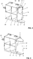
- FIG. 1 to 4 a carrier element 1 for a cleaning element 2 to be introduced into a cistern is shown.
- the Figures 1 to 2 show a first embodiment of the carrier element 1 and the Figures 3 to 4 show a second embodiment of the carrier element 1.
- both embodiments will now be described together, with the differences being discussed separately.
- cleaning element is understood to mean, for example, a cleaning tablet or a cleaning rod which slowly decomposes in the water of a cistern and thus has a cleaning effect on the cistern and the sanitary article connected downstream.
- the carrier element 1 has a support element 3 , a first retaining tab 4 protruding from the support element 3 and a second retaining tab 5 protruding from the support element 3 .
- a gap between the two holding tabs 4, 5 defines a receiving area 6 for the cleaning element 2.
- the cleaning element 2 can be placed in the receiving area 6.
- the recording area 6 can in particular in the figures 2 and 4 be recognized well, in which the cleaning element 2 than in the Recording area 6 is shown used.
- the cleaning element 2 can be clamped in the receiving area 6 by the two holding tabs 4 , 5 .
- the first retaining tab 4 is arranged to be movable, here displaceable, from a retaining position to a release position with respect to the support element 3 .
- the first retaining tab 4 is in the retaining position.
- the cleaning element 2 is essentially firmly clamped between the two holding tabs 4 , 5 .
- the release position the cleaning element 2 is released so that it can fall out of the receiving area 6 .
- the first retaining tab 4 is pushed along a longitudinal movement L from the retaining position to the release position. As a result, the clamping effect on the cleaning element 2 is eliminated.
- the first holding tab 4 is mounted in a longitudinal guide 7 on the support element 3 .
- the movement from the holding position to the release position is a longitudinal movement in the direction of the longitudinal guide 7 .
- the longitudinal guide 7 is arranged here in the area of a side surface of the support element 3 .
- the longitudinal movement bears the reference L.
- the second holding tab 5 is mounted on the support element 3 such that it can pivot about a pivot axis S.
- FIG. A spring element 12 acts on the second retaining tab 5 in such a way that the second retaining tab 5 is pressed against the receiving area 6 and thus against the cleaning element 2 lying in the receiving area 6 .
- the mounting of the second retaining tab 5 is designed in such a way that it is pivoted completely towards the support element 3 in its release position. This means that the second holding tab 5 rests on the support element 3 accordingly when there is no cleaning element 2 in the receiving area 6 .
- the receiving area 6 is further delimited between the two retaining tabs 4 , 5 by a wall surface 10 of the support element 3 . Otherwise the recording area 6 is not limited.
- the wall surface 10 is essentially at right angles to the first retaining tab 4 or to the longitudinal guide 7.
- a free end 11 of the first retaining tab 4 that is remote from the wall surface 10 lies in the retaining position in front of the wall surface 10 and in the release position this free end 11 is preferably up to the Wall surface 10 or behind the wall surface 10 movable. This increases the compactness of the carrier element 1 be increased when the first retaining tab 4 is in the release position.
- the support element 3 also has a receptacle 13 for a filter element 14 for filtering air from an odor extraction system.
- the filter element 14 is preferably mounted in the receptacle 13 in an exchangeable manner.
- the receptacle 13 essentially has a rectangular cross section.
- the filter element is cuboid and can be inserted into the receptacle 13 .
- the area in which the filter element 14 is located in the first embodiment is provided with a reinforcing cross 26 .
- the carrier element 1 according to the second embodiment has the same design as the carrier element 1 according to the first embodiment. This means that the first embodiment of the carrier element 1 can be used in a configuration with odor extraction and the second embodiment of the carrier element 1 can be used in a configuration without odor extraction, with the receptacle being identical in both configurations.
- the carrier element 1 has an actuating tab 27 in both embodiments.
- the actuating tab 27 is formed on the support element opposite the receiving area 6 and can be appropriately gripped by the user for inserting the carrier element 1 into a guide.
- the feed arrangement 15 is part of a protective plate 28 here, which can be arranged in an inspection opening of a cistern.
- the feed arrangement 15 comprises a carrier element 1 as described above and a guide 16 in which the carrier element 1 can be inserted.
- the guide 16 is here part of the protective plate 28. However, it can also be arranged on other elements in other configurations.
- the guide 16 has a release area 17 on the side of the first retaining tab 4 .
- the release area 17 is located in such a way that when the first retaining tab 4 is in its release position, the cleaning element 2 can be fed through the release area 17 into the cistern.
- the release area 17 is essentially provided by a shortened design of the guide 16 compared to the carrier element in the direction of the guide 16 .
- the carrier element 1 is shown with a further insertion depth into the guide 16 .
- the first retaining tab 4 , the second retaining tab 5 and the cleaning element 2 are in such a way that parts are already in the release area 17 .
- the cleaning element 2 falls into the cistern.
- the first retaining tab 4 was moved in the longitudinal guide 7 during insertion into the guide 16 and is in its release position.
- the first retaining tab 4 is in the release position.
- the cleaning element 2 can fall out of the receiving area 6 .
- the cleaning element 2 falls into a guide tube 29. In the installed state, the guide tube 29 protrudes into the cistern.
- the second retaining tab 5 Due to the spring element 12 and due to the force of gravity on the second retaining tab 5 , the second retaining tab 5 is folded towards the support element 3 when the cleaning element 2 has been removed from the receiving area 6 .
- This can be in the Figures 7a and 7b be recognized well.
- the second retaining tab 5 is located snugly on the support element 2 and the first retaining tab 4 is pulled back accordingly.
- the carrier element 1 In the position shown in the Figures 7a and 7b the carrier element 1 is in its fully retracted position. If the carrier element 1 is designed with the filter element 12 according to the first embodiment, the filter element 12 can be flowed through accordingly with exhaust air, which is supplied here by the fan 30 to the filter element 14 . This achieves cleaning of the exhaust air.
- the fan 30 is preferably also mounted on the protective plate 28 .
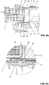
- FIG. 8a, 8b shows how the first holding tab 4 is moved from the holding position to the release position or from the release position to the holding position.
- the first holding tab 4 has a stop 8 .
- the stop 8 here has two stop surfaces 19, 20 and it is arranged on the underside of the first retaining tab 4.
- the stop 8 can be brought into engagement with a retaining element 9 fixed to the support element 3 in such a way that the first retaining tab 4 is moved relative to the support element 3 in the longitudinal guide 7 when the carrier element 1 is displaced.
- the retaining element 9 lies between the two stop surfaces 19, 20. If the carrier element 1 is pushed in further in the direction L, the stop 8 will hit the stop surface 19 on the retaining element 9. The stop 8 in combination with the retaining element 9 hold the retaining tab 4 in place so that it does not move any further despite the further displacement of the carrier element 1 .
- first retaining tab 4 pulls back with respect to the moving support element 3 and is displaced relative to the support element 3 .
- the first retaining tab 4 is moved from the retaining position into the release position and the cleaning element 2 is released accordingly, as a result of which it can fall into the cistern.
- This movement is supported by the spring action of the spring element 12 which presses the second holding tab 5 against the receiving area and thus also against the cleaning element 2 .
- the stop 8 has a second stop surface 20 .
- the first retaining tab 4 can be moved from the release position back into the retaining position on the second stop surface 20 .
- the second stop surface 20 is present on the retaining element 9 and thus the corresponding movement of the first retaining tab 4 is performed.
- the retaining element 9 is designed as a leaf spring, so that it can deflect into the area of the stop 8 .
- the spring element 21 is part of the guide 16 and has a spring arm 22 .
- the spring element 21 acts with its spring arm 22 on the carrier element 1.
- the spring element 21 provides a corresponding resistance when the carrier element 1 is pushed into the guide.
- the spring element 21 with the spring arm 22 is present on a first surface 23, which is formed on the support element 3.
- the spring arm 22 is tensioned accordingly.
- This can in the Figure 10b , which is an enlargement of the Figure 10a forms, to be recognized well. Then the spring element 21 with the spring arm 22 hits a flank 24 .
- the flank 24 is in turn arranged on the guide 16 .
- the flank 24 is inclined at an angle to the direction of insertion or to the longitudinal direction L. This means that the spring element is raised with respect to the first surface 23 as it is pushed in further and thus comes to lie over the first surface 23 . This means that the spring element comes to the height of the surface 31, which adjoins the first surface 23 at a right angle. At this level, the first surface 23 no longer provides a stop for the spring arm 22 and the spring arm 22 snaps back.
- the spring arm 22 is thus in its original position and comes in the Figure 10c shown to lie behind a second surface 25, which is also formed from the support member 3. Here the spring arm 22 then provides a stop against the movement out of the guide 16 .
Landscapes
- Health & Medical Sciences (AREA)
- Public Health (AREA)
- Life Sciences & Earth Sciences (AREA)
- Engineering & Computer Science (AREA)
- Hydrology & Water Resources (AREA)
- Water Supply & Treatment (AREA)
- Epidemiology (AREA)
- Cleaning In General (AREA)
Description
- Die vorliegende Erfindung betrifft ein Trägerelement für ein in einen Spülkasten einzubringendes Reinigungselement nach Anspruch 1.
- Aus der
EP 1 970 496 ist ein Einschubelement bekannt geworden, mit welchem ein Reinigungsstab in einen Spülkasten eingeschoben werden kann. Dabei wird der Reinigungsstab am Einschubelement gelagert und anschliessend in eine Halterung am Spülkasten eingeschoben. Der Reinigungsstab kann dann dem Spülkasten zugeführt werden. - Nachteilig an der technischen Lehre der
EP 1 970 496 ist, dass sich der Reinigungsstab im Einschubelement verkanten kann. Hierdurch wird der Reinigungsstab nicht dem Spülkasten zugeführt, was für den Benutzer nachteilig ist. - Aus der
GB 2 449 505 - Ausgehend von diesem Stand der Technik liegt der Erfindung eine Aufgabe zugrunde, eine Einschubanordnung für ein Reinigungselement eines Spülkastens anzugeben, welcher die Nachteile des Standes der Technik überwindet. Insbesondere ist es eine Aufgabe der vorliegenden Erfindung, eine Einschubanordnung anzugeben, welche eine sichere Zuführung des Reinigungselementes in den Spülkasten erlaubt.
- Diese Aufgabe löst der Gegenstand von Anspruch 1. Demgemäss umfasst ein Trägerelement für ein in einen Spülkasten einzubringendes Reinigungselement ein Supportelement, eine vom Supportelement abstehende erste Haltelasche und eine vom Supportelement abstehende zweite Haltelasche. Der Zwischenraum zwischen den beiden Haltelaschen definiert einen Aufnahmebereich für das Reinigungselement, wobei das Reinigungselement im Aufnahmebereich durch die beiden Haltelaschen einklemmbar ist. Die erste Haltelasche ist bezüglich des Supportelementes von einer Haltelage in eine Freigabelage verschiebbar angeordnet, wobei in der Haltelage das Reinigungselement zwischen den beiden Haltelaschen im Wesentlichen fest eingeklemmt ist und wobei in der Freigabelage das Reinigungselement freigegeben ist und aus dem Aufnahmebereich herausfallen kann. Die erste Haltelasche ist in einer Längsführung am Supportelement gelagert und die Bewegung von der Haltelage in die Freigabelage ist eine Längsbewegung in Richtung der Längsführung, wobei die erste Haltelasche derart gegen das Supportelement verschoben wird, dass der vom Supportelement abstehende Teil der ersten Haltelasche in der Freigabelage kleiner wird als in der Haltelage.
- Durch die Verschiebbarkeit der ersten Haltelasche ergeht der Vorteil, dass eine das Reinigungselement klemmende Haltelasche wegbewegt wird, wobei die Klemmung aufgehoben wird. Hierdurch wird sichergestellt, dass das Reinigungselement sicher aus dem Aufnahmebereich in den Spülkasten gelangen kann. Durch die verschiebbare Anordnung kann demnach ein Trägerelement geschaffen werden, mit welchem ein Reinigungselement sehr einfach in einen Spülkasten eingegeben werden kann.
- Unter der Ausdrucksweise "Lasche" wird ein vergleichsweise dünnes Element verstanden, welches sich vom Supportelement wegerstreckt.
- Unter der Ausdrucksweise "Reinigungselement" wird ein Element verstanden, welches in den Spülkasten einsetzbar ist und sich durch in Zusammenwirkung mit dem Wasser im Spülkasten langsam zersetzt und eine Reinigungswirkung für den am Spülkasten angeschlossenen Sanitärartikel aufweist. Das Reinigungselement kann auch als Reinigungstablette oder Reinigungsstab bezeichnet werden. Typischerweise hat das Reinigungselement die Form eines zylindrischen Stabes mit kreisförmigem Durchmesser. Andere Formen sind auch denkbar. Die erste Haltelasche ist gemäss der Erfindung in der Längsführung bewegbar und kann in der Längsführung relativ zum Supportelement verschoben werden.
- Unter einer Längsbewegung wird eine Bewegung in Richtung einer Längsachse verstanden. Die Bewegung wird dabei durch die Längsführung bereitgestellt. Vorzugsweise wird die Längsführung durch eine Nute am Supportelement bereitgestellt, wobei das erste Halteelement in der besagten Nute verschiebbar ist.
- Vorzugsweise ist die erste Haltelasche separat vom Supportelement ausgebildet.
- Vorzugsweise weist die erste Haltelasche einen Anschlag auf, welcher mit einem zum Supportelement feststehenden Rückhalteelement derart in den Eingriff bringbar ist, dass die erste Haltelasche bei einem Verschieben des Trägerelementes bewegt wird. Das Rückhalteelement kann beispielsweise Teil einer Führung sein, in welche das Trägerelement eingeschoben wird. Die erste Haltelasche wird dabei über den Anschlag am Rückhaltelement gehalten und durch das weitere Bewegen des Trägerelementes verschiebt sich die Haltelasche in ihrer Längsführung bezüglich des Supportelementes. Hierdurch ergeht der Vorteil, dass die Haltelasche durch das Einsetzen des Trägerelementes in die Führung verschoben werden kann.
- Die erste Haltelasche wird erfindungsgemäss derart gegen das Supportelement verschoben, dass der vom Supportelement abstehende Teil der ersten Haltelasche in der Freigabelage kleiner ist als in der Haltelage.
- Zusätzlich ist es auch denkbar, dass die zweite Haltelasche relativ zum Supportelement bewegbar ausgebildet ist, wobei der vom Supportelement abstehende Teil der zweiten Haltelasche in der Freigabelage kleiner ist als in der Haltelage.
- Typischerweise ragt das Trägerelement in der Freigabelage mit den beiden Haltelaschen in den Spülkasten ein, durch die Bewegbarkeit der ersten und/oder der zweiten Haltelaschen zum Supportelement hin ergeht der Vorteil, dass nach dem Abwurf des Reinigungselementes in den Spülkasten die erste bzw. die zweite Haltelasche zum Supportelement hin bewegt werden, was die Struktur des Supportelementes verkleinert. Hierdurch kann Raum für andere Elemente freigegeben werden.
- Vorzugsweise ist der Aufnahmebereich zwischen den beiden Haltelaschen durch eine Wandfläche des Supportelementes begrenzt, wobei die Wandfläche im Wesentlichen rechtwinklig zur ersten Haltelasche bzw. zur Längsführung orientiert ist und wobei ein entfernt zur Wandfläche liegendes freies Ende der ersten Haltelasche in der Haltelage vor der Wandfläche liegt und in der Freigabelage bis zur Wandfläche oder hinter die Wandfläche bewegbar ist. Diese konkrete Ausbildung hat den Vorteil, dass die Kompaktheit des Trägerelementes im Bereich der ersten Haltelasche nach dem Einschieben in eine Führung erhöht werden kann.
- Vorzugsweise ist die zweite Haltelasche um eine Schwenkachse verschwenkbar am Supportelement gelagert, wobei ein Federelement die zweite Haltelasche gegen den Aufnahmebereich und somit gegen das im Aufnahmebereich liegende Reinigungselement drückt. Hierdurch werden verschiedene Vorteile erzielt. Erstens wird das Reinigungselement im Aufnahmebereich durch die Wirkung des Federelementes fest gehalten. Zweitens wird beim Wegschieben der ersten Haltelasche die Federkraft des Federelementes zusätzlich für einen guten Auswurf aus dem Aufnahmebereich sorgen. Drittens wird bei eingeklappter Haltelasche die Kompaktheit des Trägerelementes im Bereich der zweiten Haltelasche nach dem Einschieben in eine Führung erhöht.
- Vorzugsweise ist die zweite Haltelasche vollständig zum Supportelement hin verschwenkbar, so dass die zweite Haltelasche am Supportelement anliegt, wenn die erste Haltelasche in der Freigabelage liegt. Hierdurch kann ein hoher Grad an Kompaktheit erreicht werden.
- Vorzugsweise wird die zweite Haltelasche zur Wandfläche hin geschwenkt und steht an der Wandfläche an.
- Vorzugsweise weist das Supportelement eine Aufnahme für ein Filterelement zur Filterung von Luft einer Geruchsabsaugung auf. Das Filterelement ist vorzugsweise austauschbar in der Aufnahme gelagert. Somit kann das Filterelement bei entsprechender Verschmutzung ausgetauscht werden. Das Filterelement kann aber auch fest im Trägerelement gelagert sein, wobei dann das Trägerelement bei Verschmutzung desselben ausgetauscht werden muss.
- Die Anordnung der Aufnahme für das Filterelement am Supportelement hat den Vorteil, dass mehrere periodisch zu ersetzende Teile, nämlich das Reinigungselement und das Filterelement, am gleichen Trägerelement angeordnet sind.
- Eine Zuführanordnung für die Zuführung eines Reinigungselementes in einen Spülkasten umfasst ein Trägerelement nach obiger Beschreibung und eine Führung, in welche das Trägerelement einschiebbar ist, wobei die Führung auf der Seite der ersten Haltelasche einen Freigabebereich aufweist, welcher derart liegt, dass wenn die erste Haltelasche in ihrer Freigabelage liegt, das Reinigungselement durch den Freigabebereich in den Spülkasten zuführbar ist.
- Die Führung ist vorzugsweise ebenfalls eine Längsführung, welche das Trägerelement auf seiner Aussenseite entsprechend führt.
- Die Führung für das Trägerelement ist vorzugsweise in die gleiche Richtung orientiert wie die Längsführung zwischen der ersten Haltelasche und dem Supportelement.
- Vorzugsweise weist die Führung auf der der ersten Haltelasche zugewandten Seite ein Rückhalteelement auf, an welchem die erste Haltelasche mit dem Anschlag bei der Einschubbewegung derart einhängt, dass bei weiterem Einschub des Trägerelementes in die Führung die erste Haltelasche in der Längsführung verschoben wird.
- Das heisst mit anderen Worten, dass durch die Bewegung des Trägerelementes in seiner Führung gleichzeitig die Haltelasche relativ zum Supportelement verschoben wird. Hierdurch ergeht der Vorteil, dass der Benutzer nur das Trägerelement betätigen muss und dass das Auswerfen des Reinigungselementes "automatisch" erfolgt.
- Vorzugsweise ist das Rückhalteelement eine Federlasche und der Anschlag weist zwei Anschlagsflächen auf, wobei bei Einschieben des Trägerelementes in die Führung eine der beiden Anschlagsflächen mit der Federlasche derart in Kontakt kommt, dass die erste Haltelasche in die Freigabelage bewegt wird und wobei beim Ausziehen des Trägerelementes aus der Führung die andere der beiden Anschlagsflächen mit der Federlasche in Kontakt kommt, derart, dass die erste Haltelasche wieder in die Haltelage bewegt wird.
- Vorzugsweise weist die Führung weiterhin ein Federelement mit einem Federarm auf. Das Federelement stellt mit dem Federarm beim Einschieben des Trägerelementes in die Führung einen Widerstand bereit. Der Federarm steht an einer ersten Fläche am Trägerelement an und wird bei der Einschubbewegung gegen dessen Federwirkung bewegt.
- Der Federarm trifft bei der Einschubewegung auf eine fest an der Führung angeordnete Flanke, welche den Federarm von der besagten ersten Fläche anhebt und bei weitergehender Einschubbewegung hinter die erste Fläche an eine zweite Fläche zu liegen kommt.
- Eine Spülkastenanordnung umfasst einen Spülkasten mit einer Revisionsöffnung und einer die Öffnung verschliessende Schutzplatte, wobei die Zuführanordnung nach obiger Beschreibung an der Schutzplatte angeordnet ist und in den Spülkasten einragt.
- Weitere Ausführungsformen sind in den abhängigen Ansprüchen angegeben.
- Bevorzugte Ausführungsformen der Erfindung werden im Folgenden anhand der Zeichnungen beschrieben, die lediglich zur Erläuterung dienen und nicht einschränkend auszulegen sind. In den Zeichnungen zeigen:
- Fig. 1
- eine perspektivische Ansicht einer ersten Ausführungsform eines Trägerelementes mit einem Filterelement für ein in einen Spülkasten einzubringendes Reinigungselement;
- Fig. 2
- die Ansicht der
Figur 1 mit dem Reinigungselement; - Fig. 3
- eine perspektivische Ansicht einer zweiten Ausführungsform eines Trägerelementes für ein in einen Spülkasten einzubringendes Reinigungselement;
- Fig. 4
- die Ansicht der
Figur 3 mit dem Reinigungselement; - Fig. 5a/5b
- eine perspektivische Ansicht einer Schutzplatte für einen Spülkasten mit einer Führung für das Trägerelement nach den vorhergehenden Figuren von vorne und hinten;
- Fig. 6a/6b
- die Ansichten der
Figuren 5a/5b , wobei das Trägerelement weiter in die Führung eingeschoben ist; - Fig. 7a/7b
- die Ansichten der
Figuren 5a/5b , wobei das Trägerelement bis zum Anschlag in die Führung eingeschoben ist; - Fig. 8a/8b
- eine Schnittdarstellung und eine Vergrösserung des Details X durch die Führung nach den vorhergehenden Figuren;
- Fig. 9a/9b
- eine perspektivische Ansicht von oben mit einem Detail eines Federelementes; und
- Fig. 10a-c
- eine weitere perspektivische Ansicht der
Figuren 9a/9b von oben. - In den
Figuren 1 bis 4 wird ein Trägerelement 1 für ein in einen Spülkasten einzubringenden Reinigungselement 2 gezeigt. DieFiguren 1 bis 2 zeigen eine erste Ausführungsform des Trägerelementes 1 und dieFiguren 3 bis 4 zeigen eine zweite Ausführungsform des Trägerelementes 1. In der Folge werden nun beide Ausführungsformen gemeinsam beschrieben, wobei auf die Unterschiede separat eingegangen wird. - Unter der Ausdrucksweise "Reinigungselement" wird beispielweise eine Reinigungstablette oder ein Reinigungsstab verstanden, welcher sich im Wasser eines Spülkastens langsam zersetzt und so eine reinigende Wirkung für den Spülkasten und für den nachgeschalteten Sanitärartikel aufweist.
- Das Trägerelement 1 weist ein Supportelement 3, eine vom Supportelement 3 abstehende erste Haltelasche 4 und eine vom Supportelement 3 abstehende zweite Haltelasche 5 auf. Ein Zwischenraum zwischen den beiden Haltelaschen 4, 5 definiert einen Aufnahmebereich 6 für das Reinigungselement 2. Im Aufnahmebereich 6 kann das Reinigungselement 2 platziert werden. Der Aufnahmebereich 6 kann insbesondere in den
Figuren 2 und4 gut erkannt werden, in welchen das Reinigungselement 2 als in den Aufnahmebereich 6 eingesetzt dargestellt ist. Das Reinigungselement 2 ist im Aufnahmebereich 6 durch die beiden Haltelaschen 4, 5 einklemmbar. - Die erste Haltelasche 4 ist bezüglich des Supportelementes 3 von einer Haltelage in eine Freigabelage bewegbar, hier verschiebbar, angeordnet. In den
Figuren 1 bis 4 befindet sich die erste Haltelasche 4 jeweils in der Haltelage. In der Haltelage ist das Reinigungselement 2 zwischen den beiden Haltelaschen 4, 5 im Wesentlichen fest eingeklemmt. In der Freigabelage ist das Reinigungselement 2 freigegeben, so dass dieses aus dem Aufnahmebereich 6 herausfallen kann. In der gezeigten Ausführungsform wird die erste Haltelasche 4 entlang einer Längsbewegung L von der Haltelage in die Freigabelage geschoben. Hierdurch fällt die Klemmwirkung auf das Reinigungselement 2 weg. - Die erste Haltelasche 4 ist in einer Längsführung 7 am Supportelement 3 gelagert. Die Bewegung von der Haltelage in die Freigabelage ist eine Längsbewegung in Richtung der Längsführung 7. Die Längsführung 7 ist hier im Bereich einer Seitenfläche des Supportelementes 3 angeordnet. Die Längsbewegung trägt das Bezugszeichen L.
- Die zweite Haltelasche 5 ist in der gezeigten Ausführungsform um eine Schwenkachse S verschwenkbar am Supportelement 3 gelagert. Ein Federelement 12 wirkt auf die zweite Haltelasche 5 derart, dass die zweite Haltelasche 5 gegen den Aufnahmebereich 6 und somit gegen das im Aufnahmebereich 6 liegende Reinigungselement 2 gedrückt wird. Die Lagerung der zweiten Haltelasche 5 ist in der gezeigten Ausführungsform dabei derart ausgebildet, dass diese in ihrer Freigabelage vollständig zum Supportelement 3 hin verschwenkt ist. Das heisst, die zweite Haltelasche 5 liegt am Supportelement 3 entsprechend an, wenn kein Reinigungselement 2 im Aufnahmebereich 6 liegt.
- Der Aufnahmebereich 6 ist zwischen den beiden Haltelaschen 4, 5 weiter durch eine Wandfläche 10 des Supportelementes 3 begrenzt. Ansonsten ist der Aufnahmebereich 6 nicht begrenzt. Die Wandfläche 10 steht im Wesentlichen rechtwinklig zur ersten Haltelasche 4 bzw. zur Längsführung 7. Ein entfernt zur Wandfläche 10 liegendes freies Ende 11 der ersten Haltelasche 4 liegt in der Haltelage vor der Wandfläche 10 und in der Freigabelage ist dieses freie Ende 11 vorzugsweise bis zur Wandfläche 10 oder aber hinter die Wandfläche 10 bewegbar. Hierdurch wird die Kompaktheit des Trägerelementes 1 erhöht werden, wenn die erste Haltelasche 4 in der Freigabelage liegt.
- In der ersten Ausführungsform gemäss den
Figuren 1 bis 2 weist das Supportelement 3 weiter eine Aufnahme 13 für ein Filterelement 14 zur Filterung von Luft einer Geruchsabsaugung auf. Das Filterelement 14 ist vorzugsweise austauschbar in der Aufnahme 13 gelagert. In der gezeigten Ausführungsform weist die Aufnahme 13 im Wesentlichen einen rechteckigen Querschnitt auf. Das Filterelement ist quaderförmig ausgebildet und kann in die Aufnahme 13 eingesetzt werden. - In der zweiten Ausführungsform ist der Bereich, in welchem in der ersten Ausführungsform das Filterelement 14 liegt, mit einem Verstärkungskreuz 26 versehen.
- Aussenseitig weist dabei das Trägerelement 1 gemäss der zweiten Ausführungsform die gleiche Ausbildung auf wie das Trägerelement 1 gemäss der ersten Ausführungsform. Das heisst, die erste Ausführungsform des Trägerelementes 1 kann in eine Konfiguration mit Geruchsabsaugung und die zweite Ausführungsform des Trägerelementes 1 kann in eine Konfiguration ohne Geruchsabsaugung eingesetzt werden, wobei die Aufnahme bei beiden Konfigurationen identisch ausgebildet sein kann.
- Weiter weist das Trägerelement 1 in beiden Ausführungsformen eine Betätigungslasche 27 auf. Die Betätigungslasche 27 ist am Supportelement gegenüber des Aufnahmebereichs 6 angeformt und kann vom Benutzer zum Einsetzen des Trägerelementes 1 in eine Führung entsprechend ergriffen werden.
- In den
Figuren 5a und 5b wird das Einsetzen des Trägerelementes 1 in eine Zuführanordnung 15 gezeigt. Die Zuführanordnung 15 ist hier Teil einer Schutzplatte 28, welche in einer Revisionsöffnung eines Spülkastens angeordnet werden kann. Die Zuführanordnung 15 umfasst ein Trägerelement 1 nach obiger Beschreibung und eine Führung 16, in welcher das Trägerelement 1 einschiebbar ist. Die Führung 16 ist hier Teil der Schutzplatte 28. Sie kann aber in anderen Konfigurationen auch an anderen Elementen angeordnet sein. - Die Führung 16 weist auf der Seite der ersten Haltelasche 4 einen Freigabebereich 17 auf.
- Der Freigabebereich 17 liegt dabei derart, dass wenn die erste Haltelasche 4 in ihrer Freigabelage liegt, das Reinigungselement 2 durch den Freigabebereich 17 in den Spülkasten zuführbar ist. In der gezeigten Ausführungsform wird der Freigabebereich 17 im Wesentlichen durch eine gegenüber dem Trägerelement in Richtung der Führung 16 gesehen verkürzte Ausbildung der Führung 16 bereitgestellt.
- In den
Figuren 5a, 5b wird das Trägerelement im Einschub in die Führung 16 gezeigt. Dabei liegt die erste Haltelasche 4 beziehungsweise die zweite Haltelasche 5 und das Reinigungselement 2 noch derart, dass diese den Freigabebereich 17 noch nicht erreicht haben. - In den
Figuren 6a und 6b wird das Trägerelement 1 mit einer weiteren Einschubtiefe in die Führung 16 gezeigt. Dabei liegen die erste Haltelasche 4, die zweite Haltelasche 5 und das Reinigungselement 2 derart, dass Teile bereits im Freigabebereich 17 liegen. Insbesondere wird in denFiguren 6a und 6b gezeigt, wie das Reinigungselement 2 in den Spülkasten fällt. Die erste Haltelasche 4 wurde während des Einschiebens in die Führung 16 in der Längsführung 7 bewegt und liegt in ihrer Freigabelage. In derFigur 6b kann gut erkannt werden, dass sich die erste Haltelasche 4 in der Freigabelage befindet. Hierdurch kann das Reinigungselement 2 aus dem Aufnahmebereich 6 herausfallen. In der gezeigten Variante fällt das Reinigungselement 2 in ein Führungsrohr 29. Das Führungsrohr 29 ragt im eingebauten Zustand in den Spülkasten ein. - Aufgrund des Federelementes 12 und aufgrund der Schwerkraft an der zweiten Haltelasche 5 wird die zweite Haltelasche 5 zum Supportelement 3 zugeklappt, wenn das Reinigungselement 2 sich aus dem Aufnahmebereich 6 entfernt hat. Dies kann in den
Figuren 7a und 7b gut erkannt werden. In derFigur 7b befindet sich die zweite Haltelasche 5 eng anliegend am Supportelement 2 und die erste Haltelasche 4 ist entsprechend zurückgezogen. In der gezeigten Stellung in denFiguren 7a und 7b befindet sich das Trägerelement 1 in seiner vollständig eingeschobenen Lage. Sofern das Trägerelement 1 gemäss der ersten Ausführungsform mit dem Filterelement 12 ausgebildet ist, kann das Filterelement 12 entsprechend mit Abluft, welche hier vom Lüfter 30 dem Filterelement 14 zugeführt wird, durchströmt werden. Hierdurch wird eine Reinigung der Abluft erreicht. Der Lüfter 30 ist vorzugsweise ebenfalls an der Schutzplatte 28 gelagert. - In den
Figuren 8a, 8b wird gezeigt, wie die erste Haltelasche 4 von der Haltelage in die Freigabelage bzw. von der Freigabelage in die Haltelage bewegt wird. Die erste Haltelasche 4 weist einen Anschlag 8 auf. Der Anschlag 8 weist hier zwei Anschlagsflächen 19, 20 auf und er ist unterseitig an der ersten Haltelasche 4 angeordnet. Der Anschlag 8 ist mit einem zum Supportelement 3 feststehenden Rückhalteelement 9 derart in den Eingriff bringbar, dass die erste Haltelasche 4 bei einem Verschieben des Trägerelementes 1 entsprechend relativ zum Supportelement 3 in der Längsführung 7 bewegt wird. - In der
Figur 8b , welche eine Vergrösserung des Details X derFigur 8a zeigt, liegt das Rückhalteelement 9 zwischen den beiden Anschlagsflächen 19, 20. Bei einem weiteren Einschieben des Trägerelementes 1 in Richtung L wird der Anschlag 8 mit der Anschlagsfläche 19 auf das Rückhalteelement 9 auftreffen. Der Anschlag 8 in Kombination mit dem Rückhalteelement 9 halten die Haltelasche 4 entsprechend fest, so dass sich diese trotz des weiteren Verschiebens des Trägerelementes 1 nicht weiter bewegt. - Das heisst, die erste Haltelasche 4 zieht sich bezüglich des sich bewegenden Supportelementes 3 zurück und wird relativ zum Supportelement 3 verschoben. Durch diese Blockierung und das weitere Vorschieben des Supportelementes 3 wird die erste Haltelasche 4 von der Haltelage in die Freigabelage bewegt und das Reinigungselement 2 wird entsprechend freigegeben, wodurch es in den Spülkasten hineinfallen kann. Diese Bewegung wird durch die Federwirkung des Federelementes 12 unterstützt, welches die zweite Haltelasche 5 gegen den Aufnahmebereich und somit auch gegen das Reinigungselement 2 drückt.
- Der Anschlag 8 weist, wie bereits erwähnt, eine zweite Anschlagsfläche 20 auf. An der zweiten Anschlagsfläche 20 kann beim Herausziehen des Trägerelementes 1 die erste Haltelasche 4 von der Freigabelage zurück in die Haltelage bewegt werden. Mit Blick auf die
Figur 8 wird dies klar, wenn die Bewegung des Supportelementes 3 beziehungsweise des Trägerelementes 1 gegen die mit dem Pfeil symbolisierte Längsrichtung erfolgt. Hierbei wird die zweite Anschlagsfläche 20 am Rückhalteelement 9 anstehen und somit wird die entsprechende Bewegung der ersten Haltelasche 4 ausgeführt. - Das Rückhalteelement 9 ist hier in der gezeigten Ausführungsform als Blattfeder ausgeführt, so dass diese in den Bereich des Anschlags 8 einfedern kann.
- In den
Figuren 9a bis 10c wird nun die Funktionsweise eines Federelementes 21 genauer erläutert. Das Federelement 21 ist Teil der Führung 16 und weist einen Federarm 22 auf. Das Federelement 21 wirkt mit seinem Federarm 22 auf das Trägerelement 1. Dabei stellt das Federelement 21 beim Einschieben des Trägerelementes 1 in die Führung einen entsprechenden Widerstand bereit. In derFigur 9b kann gut erkannt werden, dass das Federelement 21 mit dem Federarm 22 an einer erste Fläche 23, die am Supportelement 3 angeformt ist, ansteht. Beim weiteren Vorschieben des Trägerelementes 1 wird der Federarm 22 entsprechend gespannt. Dies kann in derFigur 10b , welche eine Vergrösserung derFigur 10a bildet, gut erkannt werden. Weiter trifft dann das Federelement 21 mit dem Federarm 22 auf eine Flanke 24 auf. Die Flanke 24 ist wiederum an der Führung 16 angeordnet. Die Flanke 24 ist dabei winklig geneigt zur Einschubrichtung bzw. zur Längsrichtung L ausgebildet. Das heisst, das Federelement wird bezüglich der ersten Fläche 23 bei weiterem Einschieben angehoben und kommt somit über die erste Fläche 23 zu liegen. Das heisst, das Federelement kommt auf die Höhe der Fläche 31, die sich der ersten Fläche 23 mit einem rechten Winkel anschliesst. Auf dieser Höhe stellt die erste Fläche 23 keinen Anschlag mehr für den Federarm 22 bereit und der Federarm 22 schnellt zurück. Der Federarm 22 liegt somit in seiner Ausgangsposition und kommt, in derFigur 10c gezeigt, hinter eine zweite Fläche 25 zu liegen, welche ebenfalls vom Supportelement 3 angeformt ist. Hier stellt der Federarm 22 sodann einen Anschlag gegen die Bewegung aus der Führung 16 hinaus.BEZUGSZEICHENLISTE 1 Trägerelement 21 Federelement 2 Reingungselement 22 Federarm 3 Supportelement 23 erste Fläche 4 erste Haltelasche 24 Flanke 5 zweite Haltelasche 25 zweite Fläche 6 Aufnahmebereich 26 Verstärkungskreuz 7 Längsführung 27 Betätigungslasche 8 Anschlag 28 Schutzplatte 9 Rückhalteelement 29 Führungsrohr 10 Wandfläche 30 Lüftereinheit 11 freies Ende 31 Fläche 12 Federelement L Längsrichtung 13 Aufnahme S Schwenkachse 14 Filterelement 15 Zuführanordnung 16 Führung 17 Freigabebereich 18 Rückhalteelement 19 Anschlagsfläche 20 Anschlagsfläche
Claims (13)
- Trägerelement (1) für ein in einen Spülkasten einzubringendes Reinigungselement (2), insbesondere eine sich im Wasser auflösendes Reinigungselement, umfassendein Supportelement (3),eine vom Supportelement (3) abstehende erste Haltelasche (4) undeine vom Supportelement (3) abstehende zweite Haltelasche (5),wobei der Zwischenraum zwischen den beiden Haltelaschen (4, 5) einen Aufnahmebereich (6) für das Reinigungselement (2) definiert,wobei das Reinigungselement (2) im Aufnahmebereich (6) durch die beiden Haltelaschen (4, 5) einklemmbar ist,wobei die erste Haltelasche (4) bezüglich des Supportelementes (3) von einer Haltelage in eine Freigabelage verschiebbar angeordnet ist, wobei in der Haltelage das Reinigungselement (2) zwischen den beiden Haltelaschen (4, 5) im Wesentlichen fest eingeklemmt ist und wobei in der Freigabelage das Reinigungselement (2) freigegeben ist und aus dem Aufnahmebereich (6) herausfallen kann,wobei die erste Haltelasche (4) in einer Längsführung (7) am Supportelement (3) gelagert ist und die Bewegung von der Haltelage in die Freigabelage eine Längsbewegung in Richtung der Längsführung (7) ist, undwobei die erste Haltelasche (4) derart gegen das Supportelement (3) verschoben wird, dass der vom Supportelement (4) abstehende Teil der ersten Haltelasche (4) in der Freigabelage kleiner wird als in der Haltelage.
- Trägerelement (1) nach Anspruch 1, dadurch gekennzeichnet, dass die erste Haltelasche (4) einen Anschlag (8) aufweist, welcher mit einem zum Supportelement (3) feststehenden Rückhalteelement (9) derart in den Eingriff bringbar ist, dass , bei einer Verwendung des Trägerelements, die erste Haltelasche (4) bei einem Verschieben des Trägerelementes (1) bewegt wird.
- Trägerelement (1) nach einem der vorhergehenden Ansprüche, dadurch gekennzeichnet, dass auch die zweite Haltelasche (5) derart relativ zum Supportelement (3) bewegbar ist, dass der vom Supportelement (4) abstehende Teil der zweiten Haltelasche (5) in der Freigabelage kleiner wird als in der Haltelage.
- Trägerelement (1) nach einem der vorhergehenden Ansprüche, dadurch gekennzeichnet, dass der Aufnahmebereich (6) zwischen den beiden Haltelaschen (4, 5) durch eine Wandfläche (10) des Supportelementes (3) begrenzt ist, wobei die Wandfläche (10) im Wesentlichen rechtwinklig zur ersten Haltelasche (4) bzw. zur Längsführung (7) orientiert ist und wobei ein entfernt zur Wandfläche (10) liegendes freies Ende (11) der ersten Haltelasche (4) in der Haltelage vor der Wandfläche (10) liegt und in der Freigabelage bis zur Wandfläche (10) oder hinter die Wandfläche (10) bewegbar ist.
- Trägerelement (1) nach einem der vorhergehenden Ansprüchen, dadurch gekennzeichnet, dass die zweite Haltelasche (5) um eine Schwenkachse (S) verschwenkbar am Supportelement (3) gelagert ist, wobei ein Federelement (12) die zweite Haltelasche (5) gegen den Aufnahmebereich (6) und somit gegen das im Aufnahmebereich (6) liegende Reinigungselement (2) drückt.
- Trägerelement (1) nach Anspruch 5, dadurch gekennzeichnet, dass die zweite Haltelasche (5) vollständig zum Supportelement (3) hin verschwenkbar ist, so dass die zweite Haltelasche (5) am Supportelement (3) anliegt, wenn die erste Haltelasche (4) in der Freigabelage liegt bzw. wenn kein Reinigungselement (2) im Aufnahmebereich (6) liegt.
- Trägerelement (1) nach einem der vorhergehenden Ansprüche, dadurch gekennzeichnet, dass das Supportelement (3) eine Aufnahme (13) für ein Filterelement (14) zur Filterung von Luft einer Geruchsabsaugung aufweist, wobei das Filterelement (14) vorzugsweise austauschbar in der Aufnahme gelagert ist.
- Zuführanordnung (15) für die Zuführung eines Reinigungselementes (2) in einen Spülkasten , umfassend ein Trägerelement (1) nach einem der vorhergehenden Ansprüche und eine Führung (16), in welche das Trägerelement (1) einschiebbar ist, wobei die Führung (16) auf der Seite der ersten Haltelasche (4) einen Freigabebereich (17) aufweist, welcher derart liegt, dass wenn die erste Haltelasche (4) in ihrer Freigabelage liegt, das Reinigungselement (2) durch den Freigabebereich (17) in den Spülkasten zuführbar ist.
- Zuführanordnung (15) nach Anspruch 8, dadurch gekennzeichnet, dass die Führung (16) auf der der ersten Haltelasche (4) zugewandten Seite ein Rückhalteelement (18) aufweist, an welchem die erste Haltelasche (4) mit dem Anschlag (8) bei der Einschubbewegung derart einhängt, dass bei weiterem Einschub des Trägerelementes (1) in die Führung die erste Haltelasche (4) in der Längsführung (7) verschoben wird.
- Zuführanordnung (15) nach Anspruch 9, dadurch gekennzeichnet, dass das Rückhalteelement (18) eine Federlasche ist und dass der Anschlag (8) zwei Anschlagsflächen (19, 20) aufweist, wobei bei Einschieben des Trägerelementes (1) in die Führung (16) eine der beiden Anschlagsflächen (19) mit der Federlasche (18) derart in Kontakt kommt, dass die erste Haltelasche (4) in die Freigabelage bewegt wird und wobei beim Ausziehen des Trägerelementes (1) aus der Führung die andere der beiden Anschlagsflächen (20) mit der Federlasche (18) derart in Kontakt kommt, dass die die erste Haltelasche (4) wieder in die Haltelage bewegt wird.
- Zuführanordnung (15) nach einem der Ansprüche 8 bis 10, dadurch gekennzeichnet, dass die Führung (16) weiterhin ein Federelement (21) mit einem Federarm (22) aufweist, welches beim Einschieben des Trägerelementes (1) in die Führung einen Widerstand bereitstellt, wobei der Federarm (22) an einer ersten Fläche (23) am Trägerelement (1) ansteht und wobei der Federarm bei der Einschubbewegung gegen dessen Federwirkung bewegt wird.
- Zuführanordnung (15) nach Anspruch 11, dadurch gekennzeichnet, dass der Federarm (22) bei der Einschubbewegung auf eine fest an der Führung (16) angeordnete Flanke (24) trifft, welche den Federarm (22) von der besagten ersten Fläche (23) anhebt und bei weitergehender Einschubbewegung hinter die erste Fläche (23) an eine zweite Fläche (25) zu liegen kommt.
- Spülkastenanordnung umfassend einen Spülkasten mit einer Revisionsöffnung und einer die Revisionsöffnung verschliessenden Schutzplatte (28), wobei die Zuführanordnung (15) nach einem der Ansprüche 8 bis 12 an der Schutzplatte angeordnet ist und in den Spülkasten einragt.
Priority Applications (3)
| Application Number | Priority Date | Filing Date | Title |
|---|---|---|---|
| PL18179719.2T PL3587685T3 (pl) | 2018-06-26 | 2018-06-26 | Element nośny dla wprowadzanego do spłuczki elementu czyszczącego |
| EP18179719.2A EP3587685B1 (de) | 2018-06-26 | 2018-06-26 | Trägerelement für ein in einen spülkasten einzubringendes reinigungselement |
| AU2019204453A AU2019204453B2 (en) | 2018-06-26 | 2019-06-25 | Carrier element for a cleaning element to be introduced into a cistern |
Applications Claiming Priority (1)
| Application Number | Priority Date | Filing Date | Title |
|---|---|---|---|
| EP18179719.2A EP3587685B1 (de) | 2018-06-26 | 2018-06-26 | Trägerelement für ein in einen spülkasten einzubringendes reinigungselement |
Publications (2)
| Publication Number | Publication Date |
|---|---|
| EP3587685A1 EP3587685A1 (de) | 2020-01-01 |
| EP3587685B1 true EP3587685B1 (de) | 2022-06-22 |
Family
ID=62784059
Family Applications (1)
| Application Number | Title | Priority Date | Filing Date |
|---|---|---|---|
| EP18179719.2A Active EP3587685B1 (de) | 2018-06-26 | 2018-06-26 | Trägerelement für ein in einen spülkasten einzubringendes reinigungselement |
Country Status (3)
| Country | Link |
|---|---|
| EP (1) | EP3587685B1 (de) |
| AU (1) | AU2019204453B2 (de) |
| PL (1) | PL3587685T3 (de) |
Family Cites Families (4)
| Publication number | Priority date | Publication date | Assignee | Title |
|---|---|---|---|---|
| SE530978C2 (sv) | 2007-03-13 | 2008-11-04 | Stefan Danielsson Spogardh | Doseringsanordning för vattenklosett med slädaggregat |
| GB2449505B (en) * | 2007-05-25 | 2012-02-15 | Jeyes Group Ltd | Tablet dispenser |
| NL2002473C2 (nl) * | 2009-02-01 | 2010-08-03 | V L D Verwarming Loodgieten Dakbedekking | Hulpinrichting voor het in het inbouw-spoelwaterreservoir van een toileteenheid brengen van een tabletreinigingsmiddel, van een dergelijke hulpinrichting voorziene toileteenheid, alsmede reinigingstablet. |
| PL2226437T3 (pl) * | 2009-03-06 | 2015-08-31 | Geberit Int Ag | Spłuczka i sposób wprowadzania do spłuczki dodatkowych substancji |
-
2018
- 2018-06-26 EP EP18179719.2A patent/EP3587685B1/de active Active
- 2018-06-26 PL PL18179719.2T patent/PL3587685T3/pl unknown
-
2019
- 2019-06-25 AU AU2019204453A patent/AU2019204453B2/en not_active Ceased
Also Published As
| Publication number | Publication date |
|---|---|
| AU2019204453A1 (en) | 2020-01-23 |
| PL3587685T3 (pl) | 2022-08-16 |
| EP3587685A1 (de) | 2020-01-01 |
| AU2019204453B2 (en) | 2024-08-01 |
Similar Documents
| Publication | Publication Date | Title |
|---|---|---|
| EP2117381B1 (de) | AUSSTOßER EINES BEWEGBAREN MÖBELTEILS | |
| DE2742166C2 (de) | Vorrichtung zum Ver- und Entriegeln von Formplatten einer Spritzgieß- oder Preßform | |
| DE102020109014A1 (de) | Absenk-stützen-anordnung für ein fahrrad | |
| DE102009049429A1 (de) | Schiebeanordnung | |
| EP2649906A2 (de) | Vorrichtung zum Öffnen und Schließen eines bewegbaren Möbelteils | |
| EP3153115B1 (de) | Knochenstanze mit unverlierbarem stanzschieber | |
| WO2012025519A1 (de) | Nietsetzgerät | |
| WO2016037692A1 (de) | Sanitäre auslaufarmatur | |
| DE602004006017T2 (de) | Pumpe zur abgabe von fluidprodukten | |
| EP2713822B1 (de) | Schiebeanordnung | |
| EP3098357B1 (de) | Betätigungsvorrichtung für ein ablaufventil eines spülkastens | |
| EP3195780B1 (de) | Saugdüse | |
| DE2609671C2 (de) | Mechanischer Druckbleistift mit beweglichem Minenschutzrohr | |
| DE69506828T2 (de) | Gleitkörper für einen Füllminenstift | |
| EP3587685A1 (de) | Trägerelement für ein in einen spülkasten einzubringendes reinigungselement | |
| EP0191015A1 (de) | Kombigerät zum heften und lochen von blättern insbesondere aus papier | |
| DE202009006924U1 (de) | Einzugsvorrichtung | |
| EP0600123B1 (de) | Tablettenspender mit einer unteren Ausfallöffnung | |
| DE19700213A1 (de) | Dosierpistole zur Verwendung mit Dentalpatronen | |
| EP3461980A1 (de) | Auslöseeinheit und möbelstück mit einer derartigen einheit | |
| EP1552778B1 (de) | Uriniervorrichtung zur Anbringung an einer eine Toilettenbrille und/oder einen Toilettendeckel aufweisenden Toilettenschlüssel | |
| EP4488459A1 (de) | Betätigungseinheit | |
| EP3861974A1 (de) | Kapselverschliesseinrichtung zum verschliessen zweiteiliger kapseln | |
| DE3306524A1 (de) | Dosiervorrichtung | |
| DE1431607B2 (de) | Vorrichtung zum ueberfuehren von gegenstaenden |
Legal Events
| Date | Code | Title | Description |
|---|---|---|---|
| PUAI | Public reference made under article 153(3) epc to a published international application that has entered the european phase |
Free format text: ORIGINAL CODE: 0009012 |
|
| STAA | Information on the status of an ep patent application or granted ep patent |
Free format text: STATUS: THE APPLICATION HAS BEEN PUBLISHED |
|
| AK | Designated contracting states |
Kind code of ref document: A1 Designated state(s): AL AT BE BG CH CY CZ DE DK EE ES FI FR GB GR HR HU IE IS IT LI LT LU LV MC MK MT NL NO PL PT RO RS SE SI SK SM TR |
|
| AX | Request for extension of the european patent |
Extension state: BA ME |
|
| STAA | Information on the status of an ep patent application or granted ep patent |
Free format text: STATUS: REQUEST FOR EXAMINATION WAS MADE |
|
| 17P | Request for examination filed |
Effective date: 20200310 |
|
| RBV | Designated contracting states (corrected) |
Designated state(s): AL AT BE BG CH CY CZ DE DK EE ES FI FR GB GR HR HU IE IS IT LI LT LU LV MC MK MT NL NO PL PT RO RS SE SI SK SM TR |
|
| GRAP | Despatch of communication of intention to grant a patent |
Free format text: ORIGINAL CODE: EPIDOSNIGR1 |
|
| STAA | Information on the status of an ep patent application or granted ep patent |
Free format text: STATUS: GRANT OF PATENT IS INTENDED |
|
| INTG | Intention to grant announced |
Effective date: 20211203 |
|
| GRAJ | Information related to disapproval of communication of intention to grant by the applicant or resumption of examination proceedings by the epo deleted |
Free format text: ORIGINAL CODE: EPIDOSDIGR1 |
|
| STAA | Information on the status of an ep patent application or granted ep patent |
Free format text: STATUS: REQUEST FOR EXAMINATION WAS MADE |
|
| INTC | Intention to grant announced (deleted) | ||
| GRAP | Despatch of communication of intention to grant a patent |
Free format text: ORIGINAL CODE: EPIDOSNIGR1 |
|
| STAA | Information on the status of an ep patent application or granted ep patent |
Free format text: STATUS: GRANT OF PATENT IS INTENDED |
|
| GRAS | Grant fee paid |
Free format text: ORIGINAL CODE: EPIDOSNIGR3 |
|
| GRAA | (expected) grant |
Free format text: ORIGINAL CODE: 0009210 |
|
| STAA | Information on the status of an ep patent application or granted ep patent |
Free format text: STATUS: THE PATENT HAS BEEN GRANTED |
|
| INTG | Intention to grant announced |
Effective date: 20220504 |
|
| AK | Designated contracting states |
Kind code of ref document: B1 Designated state(s): AL AT BE BG CH CY CZ DE DK EE ES FI FR GB GR HR HU IE IS IT LI LT LU LV MC MK MT NL NO PL PT RO RS SE SI SK SM TR |
|
| REG | Reference to a national code |
Ref country code: GB Ref legal event code: FG4D Free format text: NOT ENGLISH |
|
| REG | Reference to a national code |
Ref country code: CH Ref legal event code: EP |
|
| REG | Reference to a national code |
Ref country code: DE Ref legal event code: R096 Ref document number: 502018009955 Country of ref document: DE |
|
| REG | Reference to a national code |
Ref country code: AT Ref legal event code: REF Ref document number: 1499855 Country of ref document: AT Kind code of ref document: T Effective date: 20220715 |
|
| REG | Reference to a national code |
Ref country code: IE Ref legal event code: FG4D Free format text: LANGUAGE OF EP DOCUMENT: GERMAN |
|
| REG | Reference to a national code |
Ref country code: SE Ref legal event code: TRGR |
|
| REG | Reference to a national code |
Ref country code: LT Ref legal event code: MG9D |
|
| REG | Reference to a national code |
Ref country code: NL Ref legal event code: MP Effective date: 20220622 |
|
| PG25 | Lapsed in a contracting state [announced via postgrant information from national office to epo] |
Ref country code: NO Free format text: LAPSE BECAUSE OF FAILURE TO SUBMIT A TRANSLATION OF THE DESCRIPTION OR TO PAY THE FEE WITHIN THE PRESCRIBED TIME-LIMIT Effective date: 20220922 Ref country code: LT Free format text: LAPSE BECAUSE OF FAILURE TO SUBMIT A TRANSLATION OF THE DESCRIPTION OR TO PAY THE FEE WITHIN THE PRESCRIBED TIME-LIMIT Effective date: 20220622 Ref country code: HR Free format text: LAPSE BECAUSE OF FAILURE TO SUBMIT A TRANSLATION OF THE DESCRIPTION OR TO PAY THE FEE WITHIN THE PRESCRIBED TIME-LIMIT Effective date: 20220622 Ref country code: GR Free format text: LAPSE BECAUSE OF FAILURE TO SUBMIT A TRANSLATION OF THE DESCRIPTION OR TO PAY THE FEE WITHIN THE PRESCRIBED TIME-LIMIT Effective date: 20220923 Ref country code: FI Free format text: LAPSE BECAUSE OF FAILURE TO SUBMIT A TRANSLATION OF THE DESCRIPTION OR TO PAY THE FEE WITHIN THE PRESCRIBED TIME-LIMIT Effective date: 20220622 Ref country code: BG Free format text: LAPSE BECAUSE OF FAILURE TO SUBMIT A TRANSLATION OF THE DESCRIPTION OR TO PAY THE FEE WITHIN THE PRESCRIBED TIME-LIMIT Effective date: 20220922 |
|
| PG25 | Lapsed in a contracting state [announced via postgrant information from national office to epo] |
Ref country code: RS Free format text: LAPSE BECAUSE OF FAILURE TO SUBMIT A TRANSLATION OF THE DESCRIPTION OR TO PAY THE FEE WITHIN THE PRESCRIBED TIME-LIMIT Effective date: 20220622 Ref country code: LV Free format text: LAPSE BECAUSE OF FAILURE TO SUBMIT A TRANSLATION OF THE DESCRIPTION OR TO PAY THE FEE WITHIN THE PRESCRIBED TIME-LIMIT Effective date: 20220622 |
|
| PG25 | Lapsed in a contracting state [announced via postgrant information from national office to epo] |
Ref country code: NL Free format text: LAPSE BECAUSE OF FAILURE TO SUBMIT A TRANSLATION OF THE DESCRIPTION OR TO PAY THE FEE WITHIN THE PRESCRIBED TIME-LIMIT Effective date: 20220622 |
|
| PG25 | Lapsed in a contracting state [announced via postgrant information from national office to epo] |
Ref country code: SM Free format text: LAPSE BECAUSE OF FAILURE TO SUBMIT A TRANSLATION OF THE DESCRIPTION OR TO PAY THE FEE WITHIN THE PRESCRIBED TIME-LIMIT Effective date: 20220622 Ref country code: SK Free format text: LAPSE BECAUSE OF FAILURE TO SUBMIT A TRANSLATION OF THE DESCRIPTION OR TO PAY THE FEE WITHIN THE PRESCRIBED TIME-LIMIT Effective date: 20220622 Ref country code: RO Free format text: LAPSE BECAUSE OF FAILURE TO SUBMIT A TRANSLATION OF THE DESCRIPTION OR TO PAY THE FEE WITHIN THE PRESCRIBED TIME-LIMIT Effective date: 20220622 Ref country code: PT Free format text: LAPSE BECAUSE OF FAILURE TO SUBMIT A TRANSLATION OF THE DESCRIPTION OR TO PAY THE FEE WITHIN THE PRESCRIBED TIME-LIMIT Effective date: 20221024 Ref country code: ES Free format text: LAPSE BECAUSE OF FAILURE TO SUBMIT A TRANSLATION OF THE DESCRIPTION OR TO PAY THE FEE WITHIN THE PRESCRIBED TIME-LIMIT Effective date: 20220622 Ref country code: EE Free format text: LAPSE BECAUSE OF FAILURE TO SUBMIT A TRANSLATION OF THE DESCRIPTION OR TO PAY THE FEE WITHIN THE PRESCRIBED TIME-LIMIT Effective date: 20220622 Ref country code: CZ Free format text: LAPSE BECAUSE OF FAILURE TO SUBMIT A TRANSLATION OF THE DESCRIPTION OR TO PAY THE FEE WITHIN THE PRESCRIBED TIME-LIMIT Effective date: 20220622 |
|
| PG25 | Lapsed in a contracting state [announced via postgrant information from national office to epo] |
Ref country code: IS Free format text: LAPSE BECAUSE OF FAILURE TO SUBMIT A TRANSLATION OF THE DESCRIPTION OR TO PAY THE FEE WITHIN THE PRESCRIBED TIME-LIMIT Effective date: 20221022 |
|
| REG | Reference to a national code |
Ref country code: DE Ref legal event code: R097 Ref document number: 502018009955 Country of ref document: DE |
|
| PG25 | Lapsed in a contracting state [announced via postgrant information from national office to epo] |
Ref country code: MC Free format text: LAPSE BECAUSE OF FAILURE TO SUBMIT A TRANSLATION OF THE DESCRIPTION OR TO PAY THE FEE WITHIN THE PRESCRIBED TIME-LIMIT Effective date: 20220622 Ref country code: AL Free format text: LAPSE BECAUSE OF FAILURE TO SUBMIT A TRANSLATION OF THE DESCRIPTION OR TO PAY THE FEE WITHIN THE PRESCRIBED TIME-LIMIT Effective date: 20220622 |
|
| PG25 | Lapsed in a contracting state [announced via postgrant information from national office to epo] |
Ref country code: LU Free format text: LAPSE BECAUSE OF NON-PAYMENT OF DUE FEES Effective date: 20220626 Ref country code: IE Free format text: LAPSE BECAUSE OF NON-PAYMENT OF DUE FEES Effective date: 20220626 Ref country code: DK Free format text: LAPSE BECAUSE OF FAILURE TO SUBMIT A TRANSLATION OF THE DESCRIPTION OR TO PAY THE FEE WITHIN THE PRESCRIBED TIME-LIMIT Effective date: 20220622 |
|
| PLBE | No opposition filed within time limit |
Free format text: ORIGINAL CODE: 0009261 |
|
| STAA | Information on the status of an ep patent application or granted ep patent |
Free format text: STATUS: NO OPPOSITION FILED WITHIN TIME LIMIT |
|
| 26N | No opposition filed |
Effective date: 20230323 |
|
| P01 | Opt-out of the competence of the unified patent court (upc) registered |
Effective date: 20230523 |
|
| PG25 | Lapsed in a contracting state [announced via postgrant information from national office to epo] |
Ref country code: SI Free format text: LAPSE BECAUSE OF FAILURE TO SUBMIT A TRANSLATION OF THE DESCRIPTION OR TO PAY THE FEE WITHIN THE PRESCRIBED TIME-LIMIT Effective date: 20220622 |
|
| PG25 | Lapsed in a contracting state [announced via postgrant information from national office to epo] |
Ref country code: IT Free format text: LAPSE BECAUSE OF FAILURE TO SUBMIT A TRANSLATION OF THE DESCRIPTION OR TO PAY THE FEE WITHIN THE PRESCRIBED TIME-LIMIT Effective date: 20220622 |
|
| PG25 | Lapsed in a contracting state [announced via postgrant information from national office to epo] |
Ref country code: MK Free format text: LAPSE BECAUSE OF FAILURE TO SUBMIT A TRANSLATION OF THE DESCRIPTION OR TO PAY THE FEE WITHIN THE PRESCRIBED TIME-LIMIT Effective date: 20220622 Ref country code: CY Free format text: LAPSE BECAUSE OF FAILURE TO SUBMIT A TRANSLATION OF THE DESCRIPTION OR TO PAY THE FEE WITHIN THE PRESCRIBED TIME-LIMIT Effective date: 20220622 |
|
| PG25 | Lapsed in a contracting state [announced via postgrant information from national office to epo] |
Ref country code: HU Free format text: LAPSE BECAUSE OF FAILURE TO SUBMIT A TRANSLATION OF THE DESCRIPTION OR TO PAY THE FEE WITHIN THE PRESCRIBED TIME-LIMIT; INVALID AB INITIO Effective date: 20180626 |
|
| PG25 | Lapsed in a contracting state [announced via postgrant information from national office to epo] |
Ref country code: TR Free format text: LAPSE BECAUSE OF FAILURE TO SUBMIT A TRANSLATION OF THE DESCRIPTION OR TO PAY THE FEE WITHIN THE PRESCRIBED TIME-LIMIT Effective date: 20220622 |
|
| REG | Reference to a national code |
Ref country code: BE Ref legal event code: PD Owner name: GEBERIT HOLDING AG; CH Free format text: DETAILS ASSIGNMENT: CHANGE OF OWNER(S), MERGE; FORMER OWNER NAME: GEBERIT INTERNATIONAL AG Effective date: 20240528 Ref country code: BE Ref legal event code: HC Owner name: GEBERIT INTERNATIONAL AG; CH Free format text: DETAILS ASSIGNMENT: CHANGE OF OWNER(S), CHANGE OF OWNER(S) NAME; FORMER OWNER NAME: GEBERIT HOLDING AG Effective date: 20240528 |
|
| PG25 | Lapsed in a contracting state [announced via postgrant information from national office to epo] |
Ref country code: MT Free format text: LAPSE BECAUSE OF FAILURE TO SUBMIT A TRANSLATION OF THE DESCRIPTION OR TO PAY THE FEE WITHIN THE PRESCRIBED TIME-LIMIT Effective date: 20220622 |
|
| PG25 | Lapsed in a contracting state [announced via postgrant information from national office to epo] |
Ref country code: BG Free format text: LAPSE BECAUSE OF FAILURE TO SUBMIT A TRANSLATION OF THE DESCRIPTION OR TO PAY THE FEE WITHIN THE PRESCRIBED TIME-LIMIT Effective date: 20220622 |
|
| PG25 | Lapsed in a contracting state [announced via postgrant information from national office to epo] |
Ref country code: BG Free format text: LAPSE BECAUSE OF FAILURE TO SUBMIT A TRANSLATION OF THE DESCRIPTION OR TO PAY THE FEE WITHIN THE PRESCRIBED TIME-LIMIT Effective date: 20220622 |
|
| REG | Reference to a national code |
Ref country code: AT Ref legal event code: PC Ref document number: 1499855 Country of ref document: AT Kind code of ref document: T Owner name: GEBERIT INTERNATIONAL AG, CH Effective date: 20241118 |
|
| PGFP | Annual fee paid to national office [announced via postgrant information from national office to epo] |
Ref country code: PL Payment date: 20250602 Year of fee payment: 8 Ref country code: DE Payment date: 20250618 Year of fee payment: 8 |
|
| PGFP | Annual fee paid to national office [announced via postgrant information from national office to epo] |
Ref country code: GB Payment date: 20250618 Year of fee payment: 8 |
|
| PGFP | Annual fee paid to national office [announced via postgrant information from national office to epo] |
Ref country code: BE Payment date: 20250618 Year of fee payment: 8 |
|
| PGFP | Annual fee paid to national office [announced via postgrant information from national office to epo] |
Ref country code: FR Payment date: 20250626 Year of fee payment: 8 |
|
| PGFP | Annual fee paid to national office [announced via postgrant information from national office to epo] |
Ref country code: AT Payment date: 20250620 Year of fee payment: 8 |
|
| PGFP | Annual fee paid to national office [announced via postgrant information from national office to epo] |
Ref country code: SE Payment date: 20250618 Year of fee payment: 8 |
|
| PGFP | Annual fee paid to national office [announced via postgrant information from national office to epo] |
Ref country code: CH Payment date: 20250701 Year of fee payment: 8 |