EP3586790B1 - Zahnersatzplatte und verfahren zur herstellung davon, plattenzahnersatz und verfahren zur herstellung davon - Google Patents
Zahnersatzplatte und verfahren zur herstellung davon, plattenzahnersatz und verfahren zur herstellung davon Download PDFInfo
- Publication number
- EP3586790B1 EP3586790B1 EP18761121.5A EP18761121A EP3586790B1 EP 3586790 B1 EP3586790 B1 EP 3586790B1 EP 18761121 A EP18761121 A EP 18761121A EP 3586790 B1 EP3586790 B1 EP 3586790B1
- Authority
- EP
- European Patent Office
- Prior art keywords
- socket
- denture base
- denture
- artificial tooth
- basal surface
- Prior art date
- Legal status (The legal status is an assumption and is not a legal conclusion. Google has not performed a legal analysis and makes no representation as to the accuracy of the status listed.)
- Active
Links
- 238000004519 manufacturing process Methods 0.000 title claims description 29
- 238000000034 method Methods 0.000 title description 8
- 239000000463 material Substances 0.000 claims description 39
- 210000004195 gingiva Anatomy 0.000 claims description 27
- 238000005520 cutting process Methods 0.000 claims description 13
- 230000002093 peripheral effect Effects 0.000 claims description 10
- 238000013461 design Methods 0.000 claims description 2
- 239000004925 Acrylic resin Substances 0.000 description 36
- 229920000178 Acrylic resin Polymers 0.000 description 36
- 229920005989 resin Polymers 0.000 description 29
- 239000011347 resin Substances 0.000 description 29
- NIXOWILDQLNWCW-UHFFFAOYSA-N 2-Propenoic acid Natural products OC(=O)C=C NIXOWILDQLNWCW-UHFFFAOYSA-N 0.000 description 20
- 238000011960 computer-aided design Methods 0.000 description 16
- 239000000853 adhesive Substances 0.000 description 14
- 239000000178 monomer Substances 0.000 description 14
- 150000002148 esters Chemical class 0.000 description 13
- CERQOIWHTDAKMF-UHFFFAOYSA-N Methacrylic acid Chemical compound CC(=C)C(O)=O CERQOIWHTDAKMF-UHFFFAOYSA-N 0.000 description 12
- 230000001070 adhesive effect Effects 0.000 description 12
- 238000012986 modification Methods 0.000 description 12
- 230000004048 modification Effects 0.000 description 12
- SMZOUWXMTYCWNB-UHFFFAOYSA-N 2-(2-methoxy-5-methylphenyl)ethanamine Chemical compound COC1=CC=C(C)C=C1CCN SMZOUWXMTYCWNB-UHFFFAOYSA-N 0.000 description 11
- 239000000805 composite resin Substances 0.000 description 11
- 210000001909 alveolar process Anatomy 0.000 description 9
- 229920001971 elastomer Polymers 0.000 description 8
- 238000003801 milling Methods 0.000 description 7
- 229920003229 poly(methyl methacrylate) Polymers 0.000 description 7
- 229920000642 polymer Polymers 0.000 description 7
- 238000006116 polymerization reaction Methods 0.000 description 7
- 239000004926 polymethyl methacrylate Substances 0.000 description 7
- 239000005060 rubber Substances 0.000 description 7
- 125000005907 alkyl ester group Chemical group 0.000 description 6
- VVQNEPGJFQJSBK-UHFFFAOYSA-N Methyl methacrylate Chemical compound COC(=O)C(C)=C VVQNEPGJFQJSBK-UHFFFAOYSA-N 0.000 description 5
- 235000019646 color tone Nutrition 0.000 description 5
- 239000011350 dental composite resin Substances 0.000 description 5
- HWSSEYVMGDIFMH-UHFFFAOYSA-N 2-[2-[2-(2-methylprop-2-enoyloxy)ethoxy]ethoxy]ethyl 2-methylprop-2-enoate Chemical compound CC(=C)C(=O)OCCOCCOCCOC(=O)C(C)=C HWSSEYVMGDIFMH-UHFFFAOYSA-N 0.000 description 4
- BAPJBEWLBFYGME-UHFFFAOYSA-N Methyl acrylate Chemical compound COC(=O)C=C BAPJBEWLBFYGME-UHFFFAOYSA-N 0.000 description 4
- AMFGWXWBFGVCKG-UHFFFAOYSA-N Panavia opaque Chemical compound C1=CC(OCC(O)COC(=O)C(=C)C)=CC=C1C(C)(C)C1=CC=C(OCC(O)COC(=O)C(C)=C)C=C1 AMFGWXWBFGVCKG-UHFFFAOYSA-N 0.000 description 4
- 230000014509 gene expression Effects 0.000 description 4
- 210000002050 maxilla Anatomy 0.000 description 4
- 239000000243 solution Substances 0.000 description 4
- 238000010146 3D printing Methods 0.000 description 3
- 229920000800 acrylic rubber Polymers 0.000 description 3
- 238000001723 curing Methods 0.000 description 3
- 239000011888 foil Substances 0.000 description 3
- 239000011256 inorganic filler Substances 0.000 description 3
- 229910003475 inorganic filler Inorganic materials 0.000 description 3
- 210000004373 mandible Anatomy 0.000 description 3
- 239000011159 matrix material Substances 0.000 description 3
- 229910052751 metal Inorganic materials 0.000 description 3
- 239000002184 metal Substances 0.000 description 3
- 210000000214 mouth Anatomy 0.000 description 3
- 229920000058 polyacrylate Polymers 0.000 description 3
- 230000000379 polymerizing effect Effects 0.000 description 3
- 229920001296 polysiloxane Polymers 0.000 description 3
- VYPSYNLAJGMNEJ-UHFFFAOYSA-N silicon dioxide Inorganic materials O=[Si]=O VYPSYNLAJGMNEJ-UHFFFAOYSA-N 0.000 description 3
- RMCCONIRBZIDTH-UHFFFAOYSA-N 2-(2-methylprop-2-enoyloxy)ethyl 1,3-dioxo-2-benzofuran-5-carboxylate Chemical compound CC(=C)C(=O)OCCOC(=O)C1=CC=C2C(=O)OC(=O)C2=C1 RMCCONIRBZIDTH-UHFFFAOYSA-N 0.000 description 2
- VTYYLEPIZMXCLO-UHFFFAOYSA-L Calcium carbonate Chemical compound [Ca+2].[O-]C([O-])=O VTYYLEPIZMXCLO-UHFFFAOYSA-L 0.000 description 2
- OKTJSMMVPCPJKN-UHFFFAOYSA-N Carbon Chemical compound [C] OKTJSMMVPCPJKN-UHFFFAOYSA-N 0.000 description 2
- 239000005062 Polybutadiene Substances 0.000 description 2
- 239000004820 Pressure-sensitive adhesive Substances 0.000 description 2
- MCMNRKCIXSYSNV-UHFFFAOYSA-N Zirconium dioxide Chemical compound O=[Zr]=O MCMNRKCIXSYSNV-UHFFFAOYSA-N 0.000 description 2
- 125000003647 acryloyl group Chemical group O=C([*])C([H])=C([H])[H] 0.000 description 2
- 125000000217 alkyl group Chemical group 0.000 description 2
- 229910052799 carbon Inorganic materials 0.000 description 2
- 239000004568 cement Substances 0.000 description 2
- 239000003086 colorant Substances 0.000 description 2
- 230000000052 comparative effect Effects 0.000 description 2
- 238000007796 conventional method Methods 0.000 description 2
- SUPCQIBBMFXVTL-UHFFFAOYSA-N ethyl 2-methylprop-2-enoate Chemical compound CCOC(=O)C(C)=C SUPCQIBBMFXVTL-UHFFFAOYSA-N 0.000 description 2
- MKVYSRNJLWTVIK-UHFFFAOYSA-N ethyl carbamate;2-methylprop-2-enoic acid Chemical compound CCOC(N)=O.CC(=C)C(O)=O.CC(=C)C(O)=O MKVYSRNJLWTVIK-UHFFFAOYSA-N 0.000 description 2
- 239000000945 filler Substances 0.000 description 2
- 229910052602 gypsum Inorganic materials 0.000 description 2
- 239000010440 gypsum Substances 0.000 description 2
- 238000002347 injection Methods 0.000 description 2
- 239000007924 injection Substances 0.000 description 2
- 230000013011 mating Effects 0.000 description 2
- -1 methacryloyl group Chemical group 0.000 description 2
- 230000000704 physical effect Effects 0.000 description 2
- 239000000049 pigment Substances 0.000 description 2
- 229920002857 polybutadiene Polymers 0.000 description 2
- 239000003505 polymerization initiator Substances 0.000 description 2
- 239000000843 powder Substances 0.000 description 2
- 229920002379 silicone rubber Polymers 0.000 description 2
- 239000004945 silicone rubber Substances 0.000 description 2
- 239000000126 substance Substances 0.000 description 2
- HRPVXLWXLXDGHG-UHFFFAOYSA-N Acrylamide Chemical compound NC(=O)C=C HRPVXLWXLXDGHG-UHFFFAOYSA-N 0.000 description 1
- 239000004593 Epoxy Substances 0.000 description 1
- IMROMDMJAWUWLK-UHFFFAOYSA-N Ethenol Chemical compound OC=C IMROMDMJAWUWLK-UHFFFAOYSA-N 0.000 description 1
- JIGUQPWFLRLWPJ-UHFFFAOYSA-N Ethyl acrylate Chemical compound CCOC(=O)C=C JIGUQPWFLRLWPJ-UHFFFAOYSA-N 0.000 description 1
- 244000043261 Hevea brasiliensis Species 0.000 description 1
- 241000339287 Ochna arborea Species 0.000 description 1
- 244000268528 Platanus occidentalis Species 0.000 description 1
- 239000006087 Silane Coupling Agent Substances 0.000 description 1
- 241000209140 Triticum Species 0.000 description 1
- 235000021307 Triticum Nutrition 0.000 description 1
- BZHJMEDXRYGGRV-UHFFFAOYSA-N Vinyl chloride Chemical compound ClC=C BZHJMEDXRYGGRV-UHFFFAOYSA-N 0.000 description 1
- 229920006223 adhesive resin Polymers 0.000 description 1
- PNEYBMLMFCGWSK-UHFFFAOYSA-N aluminium oxide Inorganic materials [O-2].[O-2].[O-2].[Al+3].[Al+3] PNEYBMLMFCGWSK-UHFFFAOYSA-N 0.000 description 1
- MTAZNLWOLGHBHU-UHFFFAOYSA-N butadiene-styrene rubber Chemical compound C=CC=C.C=CC1=CC=CC=C1 MTAZNLWOLGHBHU-UHFFFAOYSA-N 0.000 description 1
- QHIWVLPBUQWDMQ-UHFFFAOYSA-N butyl prop-2-enoate;methyl 2-methylprop-2-enoate;prop-2-enoic acid Chemical compound OC(=O)C=C.COC(=O)C(C)=C.CCCCOC(=O)C=C QHIWVLPBUQWDMQ-UHFFFAOYSA-N 0.000 description 1
- 229910000019 calcium carbonate Inorganic materials 0.000 description 1
- 239000000919 ceramic Substances 0.000 description 1
- 229910010293 ceramic material Inorganic materials 0.000 description 1
- 239000004927 clay Substances 0.000 description 1
- 238000004040 coloring Methods 0.000 description 1
- 150000001875 compounds Chemical class 0.000 description 1
- 238000000748 compression moulding Methods 0.000 description 1
- 210000003298 dental enamel Anatomy 0.000 description 1
- 239000005548 dental material Substances 0.000 description 1
- 210000004268 dentin Anatomy 0.000 description 1
- 230000008021 deposition Effects 0.000 description 1
- 230000000694 effects Effects 0.000 description 1
- 239000000806 elastomer Substances 0.000 description 1
- 125000005670 ethenylalkyl group Chemical group 0.000 description 1
- RTZKZFJDLAIYFH-UHFFFAOYSA-N ether Substances CCOCC RTZKZFJDLAIYFH-UHFFFAOYSA-N 0.000 description 1
- 239000010433 feldspar Substances 0.000 description 1
- 235000013312 flour Nutrition 0.000 description 1
- 230000009969 flowable effect Effects 0.000 description 1
- 229920001519 homopolymer Polymers 0.000 description 1
- 239000003112 inhibitor Substances 0.000 description 1
- 239000003999 initiator Substances 0.000 description 1
- 238000001746 injection moulding Methods 0.000 description 1
- 238000007641 inkjet printing Methods 0.000 description 1
- 239000004922 lacquer Substances 0.000 description 1
- 239000000203 mixture Substances 0.000 description 1
- 238000000465 moulding Methods 0.000 description 1
- 229920003052 natural elastomer Polymers 0.000 description 1
- 229920001194 natural rubber Polymers 0.000 description 1
- PNJWIWWMYCMZRO-UHFFFAOYSA-N pent‐4‐en‐2‐one Natural products CC(=O)CC=C PNJWIWWMYCMZRO-UHFFFAOYSA-N 0.000 description 1
- 238000000016 photochemical curing Methods 0.000 description 1
- 229920000728 polyester Polymers 0.000 description 1
- 239000010453 quartz Substances 0.000 description 1
- 239000002994 raw material Substances 0.000 description 1
- 230000009257 reactivity Effects 0.000 description 1
- 238000000110 selective laser sintering Methods 0.000 description 1
- 239000000377 silicon dioxide Substances 0.000 description 1
- 229920002050 silicone resin Polymers 0.000 description 1
- 238000005728 strengthening Methods 0.000 description 1
- 229920003048 styrene butadiene rubber Polymers 0.000 description 1
- 238000012719 thermal polymerization Methods 0.000 description 1
- 229920002803 thermoplastic polyurethane Polymers 0.000 description 1
- 210000000332 tooth crown Anatomy 0.000 description 1
Images


Classifications
-
- A—HUMAN NECESSITIES
- A61—MEDICAL OR VETERINARY SCIENCE; HYGIENE
- A61C—DENTISTRY; APPARATUS OR METHODS FOR ORAL OR DENTAL HYGIENE
- A61C13/00—Dental prostheses; Making same
- A61C13/01—Palates or other bases or supports for the artificial teeth; Making same
-
- A—HUMAN NECESSITIES
- A61—MEDICAL OR VETERINARY SCIENCE; HYGIENE
- A61C—DENTISTRY; APPARATUS OR METHODS FOR ORAL OR DENTAL HYGIENE
- A61C13/00—Dental prostheses; Making same
- A61C13/0003—Making bridge-work, inlays, implants or the like
- A61C13/0004—Computer-assisted sizing or machining of dental prostheses
-
- A—HUMAN NECESSITIES
- A61—MEDICAL OR VETERINARY SCIENCE; HYGIENE
- A61C—DENTISTRY; APPARATUS OR METHODS FOR ORAL OR DENTAL HYGIENE
- A61C13/00—Dental prostheses; Making same
- A61C13/0003—Making bridge-work, inlays, implants or the like
- A61C13/0006—Production methods
- A61C13/0019—Production methods using three dimensional printing
-
- A—HUMAN NECESSITIES
- A61—MEDICAL OR VETERINARY SCIENCE; HYGIENE
- A61C—DENTISTRY; APPARATUS OR METHODS FOR ORAL OR DENTAL HYGIENE
- A61C13/00—Dental prostheses; Making same
- A61C13/08—Artificial teeth; Making same
-
- A—HUMAN NECESSITIES
- A61—MEDICAL OR VETERINARY SCIENCE; HYGIENE
- A61C—DENTISTRY; APPARATUS OR METHODS FOR ORAL OR DENTAL HYGIENE
- A61C13/00—Dental prostheses; Making same
- A61C13/08—Artificial teeth; Making same
- A61C13/081—Making teeth by casting or moulding
-
- A—HUMAN NECESSITIES
- A61—MEDICAL OR VETERINARY SCIENCE; HYGIENE
- A61C—DENTISTRY; APPARATUS OR METHODS FOR ORAL OR DENTAL HYGIENE
- A61C13/00—Dental prostheses; Making same
- A61C13/08—Artificial teeth; Making same
- A61C13/087—Artificial resin teeth
-
- A—HUMAN NECESSITIES
- A61—MEDICAL OR VETERINARY SCIENCE; HYGIENE
- A61C—DENTISTRY; APPARATUS OR METHODS FOR ORAL OR DENTAL HYGIENE
- A61C13/00—Dental prostheses; Making same
- A61C13/10—Fastening of artificial teeth to denture palates or the like
-
- A—HUMAN NECESSITIES
- A61—MEDICAL OR VETERINARY SCIENCE; HYGIENE
- A61C—DENTISTRY; APPARATUS OR METHODS FOR ORAL OR DENTAL HYGIENE
- A61C13/00—Dental prostheses; Making same
- A61C13/10—Fastening of artificial teeth to denture palates or the like
- A61C13/1003—Fastening of artificial teeth to denture palates or the like by embedding in base material
- A61C13/1006—Fastening of artificial teeth to denture palates or the like by embedding in base material characterised by a tooth shape which improves retention
-
- A—HUMAN NECESSITIES
- A61—MEDICAL OR VETERINARY SCIENCE; HYGIENE
- A61C—DENTISTRY; APPARATUS OR METHODS FOR ORAL OR DENTAL HYGIENE
- A61C13/00—Dental prostheses; Making same
- A61C13/10—Fastening of artificial teeth to denture palates or the like
- A61C13/1003—Fastening of artificial teeth to denture palates or the like by embedding in base material
- A61C13/1009—Anchorage members, e.g. pins or bars; Means or methods for affixing pins to porcelain teeth
-
- A—HUMAN NECESSITIES
- A61—MEDICAL OR VETERINARY SCIENCE; HYGIENE
- A61C—DENTISTRY; APPARATUS OR METHODS FOR ORAL OR DENTAL HYGIENE
- A61C13/00—Dental prostheses; Making same
- A61C13/10—Fastening of artificial teeth to denture palates or the like
- A61C13/1003—Fastening of artificial teeth to denture palates or the like by embedding in base material
- A61C13/1013—Arch forms
- A61C13/1016—Methods or apparatus for mounting, holding or positioning a set of teeth
Definitions
- the present invention relates to a denture base and a method of manufacturing the same, and a denture.
- EP 1 444 965 A2 relates to a device and a method for manufacturing a dental prosthesis with which and in which the data records for fabricated teeth are fitted into a virtual model of the oral situation. It is possible to subsequently directly manufacture the denture base or to insert the fabricated teeth in the model.
- the artificial teeth are embedded in the denture base to fix the artificial teeth.
- Patients who require dentures have alveolar ridges of various different heights.
- the thickness of the denture base cannot be sufficiently ensured in regard to the areas directly under the artificial teeth to achieve a balance between fitting feeling and occlusal feeling.
- collar portions of the artificial teeth i.e., the portions embedded in the denture base
- the invention also provides a method of manufacturing a denture base comprising a cutting step of cutting a denture base material to obtain the denture base according to the invention.
- the invention further provides denture comprising the denture base according to invention and an artificial tooth according to the inventionattached to the socket of the denture base.
- An embodiment of the present invention is configured as described above, so there can be provided a denture base whose manufacturing burden can be reduced, and a denture having the denture base and an artificial tooth embedded therein.
- the area where the artificial tooth is to be embedded in the denture base is small, so the step of cutting the artificial tooth can be significantly reduced or eliminated even in a denture for a patient with a high alveolar ridge.
- the area of adhesion to the artificial tooth is increased because the basal surface of the denture base has a convex shape, and the fixing force of the artificial tooth can be raised.
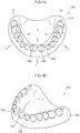
- a denture 300 pertaining to a first embodiment includes a denture base 100 and plural artificial teeth 200 attached to a base portion 102 of the denture base 100. Furthermore, the area of the base portion 102 that is seen as gingiva in a state in which the artificial teeth 200 are attached is referred to as a gingival area 110.
- FIG. 6 shows a denture 300 for a maxilla, the denture and the denture base may also be for a mandible.
- the denture base 100 has the base portion 102, which is the part to which the artificial teeth 200 are to be attached.
- a plurality of sockets 120 into which the artificial teeth 200 (see FIG. 6 ) are placed and fixed are formed adjacent to each other along a tooth row.
- the denture base 100 of FIG. 1A and FIG. 1B is shown in a state in which the sockets 120 are facing upward.
- the up and down direction and heights relating to the denture base 100 and referred to in the description below all follow the up and down direction and heights in the state shown in FIG. 1A and FIG. 1B .
- FIG. 1A and FIG. 1B Furthermore, in FIG.
- the arrows indicated by the curved dashed line between D-D indicate a direction along the tooth row.
- the direction of the arrows denoted by L represents a labial side or a buccal side
- the direction of the arrows denoted by T represents a lingual side.
- the expressions "direction along the tooth row,” “labial side” (which, in the present invention, unless otherwise specified, is expressed in this way as a concept that also includes “buccal side”), and "lingual side” referred to in the description below are directions indicated respectively by these arrows in FIG. 1A . Directions are indicated by these arrows where appropriate also in the drawings below.
- the sockets 120 are clearly demarcated by step portions 112 from the gingival area 110.
- the surfaces of the sockets 120 are lower by an amount corresponding to the height of the step portions 112 with respect to the gingival area 110.
- interdental papilla areas 114 are formed on both ends of each of the sockets 120 along the tooth row.
- the interdental papilla areas 114 include areas that form interdental papillae between the artificial teeth 200 that are to be attached to the sockets 120 and adjacent teeth.
- adjacent teeth means adjacent artificial teeth 120, but if the denture 300 is a partial denture, there are also cases where the adjacent teeth are natural teeth to which the partial denture is adjacent.
- Each of basal surfaces 130 which are surfaces of the sockets 120 to which the artificial teeth 200 are to be fixed, has a ridge shape interconnecting the interdental papilla areas 114 positioned on both ends of the corresponding socket 120.
- These ridge-shaped areas are referred to as socket apex portions 138.
- the socket apex portions 138 are the highest parts of the basal surfaces 130 of the sockets 120.
- the expression "ridge-shaped" in relation to the socket apex portions 138 refers to a state in which the sockets 120 are facing upward as in the drawings.
- the "ridges" are in the lowest position in the case of a denture 300 for a maxilla and conversely are in the highest position in the case of a denture 300 for a mandible.
- Each of the basal surfaces 130 of the sockets 120 is configured by a surface that is convex overall including the socket apex portion 138.
- surface that is convex overall means that basically the overall surface has a three-dimensional shape that is convex, and means that it is desirable for the overall surface to be formed as a convexly curved surface but that it is alright if the overall surface includes a flat surface in a part thereof or if the overall surface is formed in a convex shape by a combination of plural flat surfaces.
- a basal surface 132 on the labial side of each socket 120 is formed in a convex shape that slopes downward toward the labial side.
- the basal surface 132 on the labial side may also be formed as a flat surface.
- a basal surface 134 on the lingual side is also formed in a convex shape that slopes downward toward the lingual side.
- the basal surface 134 on the lingual side may also be formed as a flat surface.
- both the basal surface 132 on the labial side and the basal surface 134 on the lingual side may also be formed as flat surfaces.
- a peripheral area 136 of the basal surface 130 of each socket 120 is in mutually continuous abutment with the step portion 112 of the gingival area 110 on both the labial side and the lingual side. That is, the peripheral area 136 directly borders on the step portion 112, without a recessed structure such as a groove or a valley portion being interposed between the peripheral area 136 and the step portion 112. Furthermore, the step portion 112 also directly borders on the peripheral area 136, without a recessed structure such as a groove or a pocket being interposed between the step portion 112 and the peripheral area 136. This is what is expressed as "mutually continuous abutment" as described above.
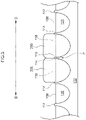
- FIG. 3 schematically shows, in a front view, a state in which the artificial teeth 200 are attached to some of the sockets 120.
- the interdental papilla areas 114 of the gingival area 110 are a little higher, by an amount corresponding to the step portion 112, than the height of the socket apex portions 138.
- this area is hidden between the teeth and cannot be seen from the labial side.
- the height of an apex portion 116 which is the highest part of the area (i.e., an interdental papilla P in the drawing) that can be seen from the labial side in the interdental papilla area 114 positioned between the two artificial teeth 200 that are adjacent to each other, is substantially the same as the height of the socket apex portions 138.
- the height of the socket apex portions 138 and the height of the apex portions 116 of the interdental papilla areas 114 are substantially the same means that it suffices to be able to perceive both heights as being the same at a glance, and this does not require that the heights be strictly the same. Thus, it is alright if there are cases where, in reality, either one is slightly higher than the other.
- FIG. 15A, FIG. 15B , and FIG. 15C The height of the apex portions 116 of the interdental papilla areas 114 that are seen from the labial side in a state in which the artificial teeth 200 are attached to the sockets 120 will be specifically described using FIG. 15A, FIG. 15B , and FIG. 15C .
- straight line a is a straight line that passes through the highest points of adjacent interdental papilla areas 114.
- Straight line b is a straight line that passes through a socket lower end portion 139 and is parallel to straight line a.
- Plane S1 is a plane that passes through straight line a and straight line b that are adjacent to each other.
- distance D1 is the distance between straight line a and straight line b.
- straight line c is a straight line that is parallel to straight line b and passes through the socket apex portion 138.
- plane S2 is a plane that passes through straight line b and straight line c.
- distance D2 is the distance between straight line b and straight line c. Plane S1 and plane S2 are not invariably limited to being in the same plane.
- the distance D3 is substantially the same as the distance D2 in a case where D1:D2 is 1:1.2 to 1:08, preferably a case where D1:D2 is 1:1.1 to 1:0.9, and more preferably a case where D1:D2 is 1:1 to 1:0.95.
- the socket apex portions 138 are substantially the same height as the apex portions 116 of the interdental papilla areas 114 that are seen from the labial side in a state in which the artificial teeth are attached to the sockets, the socket apex portions 138 may also be in a higher position than the apex portions 116 of the interdental papilla areas 114, that is, in a position where D3 ⁇ D2 in FIG. 15C .
- all the sockets may be formed as sockets having the socket apex portion 138 and having the basal surface 130 configured by a surface that is convex overall such as shown in FIG. 1A and FIG. 1B and also FIG. 2A to FIG. 2E , or sockets having the basal surface 130 may also be mixed with sockets having the conventional concave shape. Examples where sockets of different shapes are mixed together include using sockets having the basal surface 130 for anterior teeth and using sockets with the conventional concave shape for posterior teeth.
- the material of the denture base 100 serving as the denture base material is not particularly limited.
- acrylic resin is preferred because it is suited for manufacture using a CAD/CAM system (a manufacturing system equipped with a CAD (Computer Aided Design) system unit and a CAM (Computer Aided Manufacturing) system unit) as described later and because it has excellent adhesion to resin teeth made of commercially available acrylic resin.
- the acrylic resin is a polymer including at least one type selected from a group comprising a structural unit derived from acrylic acid, a structural unit derived from methacrylic acid, a structural unit derived from esters of acrylic acid, and a structural unit derived from esters of methacrylic acid.
- the acrylic resin in the present specification is a polymer obtained by polymerizing a monomer component including at least one type (hereinafter also referred to as an "acrylic monomer") selected from a group comprising acrylic acid, methacrylic acid, esters of acrylic acid, and esters of methacrylic acid.
- a monomer component including at least one type hereinafter also referred to as an "acrylic monomer” selected from a group comprising acrylic acid, methacrylic acid, esters of acrylic acid, and esters of methacrylic acid.
- the acrylic monomer that is at least a part of the raw material of the acrylic resin may be a monofunctional acrylic monomer or may be a polyfunctional acrylic monomer.
- monofunctional acrylic monomers include acrylic acid, methacrylic acid, esters of acrylic acid including at least one acryloyl group in one molecule, and esters of methacrylic acid including at least one methacryloyl group in one molecule.
- polyfunctional acrylic monomers examples include esters of acrylic acid including two or more acryloyl groups in one molecule and esters of methacrylic acid including two or more methacryloyl groups in one molecule.
- esters of acrylic acid alkyl esters of acrylic acid are preferred.
- alkyl esters of acrylic acid in which a carbon number of the alkyl group included in the site of the alkyl ester is 1 to 4 are more preferred, methyl acrylate and ethyl acrylate are even more preferred, and methyl acrylate is particularly preferred.
- esters of methacrylic acid alkyl esters of methacrylic acid are preferred.
- alkyl esters of methacrylic acid in which a carbon number of the alkyl group included in the site of the alkyl ester is 1 to 4 are preferred, methyl methacrylate and ethyl methacrylate are more preferred, and methyl methacrylate is particularly preferred.
- the acrylic resin is a polymer obtained by polymerizing a monomer component including a monofunctional acrylic monomer from a viewpoint of reactivity and productivity.
- the acrylic resin is a polymer obtained by polymerizing a monomer component including 50 mass% or more (preferably 80 mass% or more, more preferably 90 mass% or more, and even more preferably 95 mass% or more) of a monofunctional acrylic monomer.
- acrylic resin particularly preferred is a polymer including a structural unit derived from methyl methacrylate, and most preferred is a homopolymer of methyl methacrylate (polymethyl methacrylate (PMMA)).
- PMMA polymethyl methacrylate
- the acrylic resin may also include rubber from the viewpoint of impact resistance.
- Examples of types of the rubber include acrylic rubber, butadiene rubber, butadiene-acrylic rubber, butadiene-styrene rubber, and silicone rubber.
- the acrylic resin includes rubber
- it suffices to select the rubber type in consideration of appropriate physical properties but butadiene rubber or butadiene-acrylic rubber is preferred in consideration of a balance in physical properties such as hardness and impact resistance.
- the denture base 100 may be colored to a color tone close to that of gingiva from an aesthetic viewpoint. It suffices to use a pigment, dye, or coloring matter, for example, to color the denture base 100.
- the denture base 100 may be a denture base for a complete denture or may be a denture base for a partial denture.
- the denture base 100 may be a denture base for a maxillary denture, or may be a denture base for a mandibular denture, or may be a set of a maxillary denture and a mandibular denture.
- a CAD/CAM system In the manufacture of the denture base 100, as an example, a CAD/CAM system can be used. The manufacturing step resulting from the CAD/CAM system is referred to as a "CAD/CAM step.”
- the CAD system unit designs and creates, on the basis of 3D surface profile information of an oral cavity and 3D profile information of artificial teeth 200, profile information of the denture base 100 as digital data using a computer.
- the digital data also includes profile information of the sockets 120.
- the CAM system unit has, for example, a milling machine.
- the CAM system unit acquires the profile information that has been formed by the CAD system unit and forms, with the milling machine, the denture base 100. That is, the milling machine cuts, on the basis of the profile data of the denture base 100 that has been input, a resin block formed of the denture base material, whereby the denture base 100 is obtained.
- At least a part of the step of forming the denture base 100 includes a cutting step (e.g., cutting by the milling machine described above).
- a cutting step e.g., cutting by the milling machine described above.
- the sockets 120 can be formed with a high degree of precision.
- the profile information of the denture base 100 that has been obtained by the CAD system unit is included.
- the CAM unit forms the material of the denture base 100 to manufacture the denture base 100.
- the denture base 100 with the desired shape can be formed efficiently and with a high degree of precision.
- the profile information of the denture base 100 also includes the profile information of the sockets 120. Consequently, the denture base 100 having the sockets 120 may also be formed only by the CAD/CAM step using the milling machine.
- a manual work by a worker may be included as a part of the cutting step.
- a manufacturing system having a 3D printer may also be used instead of the milling machine of the manufacturing system described above.
- the CAM system unit acquires the profile information that has been formed by the CAD system unit, and the denture base 100 is formed by 3D printing using the 3D printer that is a part of the CAM system unit.
- the 3D printer forms the denture base 100 by layering the denture base material one layer at a time on the basis of the profile data of the denture base 100 that has been input.
- the 3D printer may employ any of stereolithography, selective laser sintering, fused deposition modeling, and inkjet printing.
- the profile information of the denture base 100 also includes the profile information of the sockets 120. Consequently, for example, the denture base 100 having the sockets 120 may also be formed only by the CAD/CAM step using the 3D printer.
- the denture base 100 in the step of forming the denture base 100 by 3D printing, the denture base 100, including also the shape of the sockets 120, can be formed only with the 3D printer. Thereby, a step of forming the sockets 120 by hand, for example, can be eliminated, or modification of the shape of the sockets 120 by hand, for example, can be minimized.
- the CAM unit As the system for manufacturing the denture base 100, it suffices for the CAM unit to have at least one of a milling machine and a 3D printer, and the CAM unit may also have both.
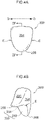
- the artificial tooth 200 has a basal surface 230 of the artificial tooth 200 that serves as a surface that is to be adhered to the basal surface 130 of the socket 120 of the denture base 100.
- the artificial tooth 200 of FIG. 4A to FIG. 4D is to be attached to the denture base 100 shown in FIG. 1A and FIG. 1B and is shown in a state in which its occlusal surface is facing upward. That is, the up and down direction of the artificial tooth 200 of FIG. 4A to FIG. 4D is the same as the up and down direction of the denture base 100 of FIG. 1A and FIG. 1B .
- the up and down direction and heights relating to the artificial tooth 200 and referred to in the following description all mean the up and down direction and heights in the state shown in FIG. 4A to FIG. 4D .
- the basal surface 230 of the artificial tooth 200 is configured by a surface that is concave overall so as to correspond to the basal surface 130 of the corresponding socket 120.
- the expression "surface that is concave overall” means that basically the overall surface has a three-dimensional shape that is concave, and means that it is desirable for the overall surface to be formed as a concavely curved surface, but in a case where part or all of the basal surface 130 of the socket 120 is formed by a flat surface, as long as the overall surface is formed in a concave shape, the basal surface 230 may also be configured by a flat surface as a part corresponding to that flat surface.
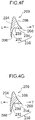
- the area -corresponding to the socket apex portion 138 - of the basal surface 230 of the artificial tooth 200 configured as a surface that is concave overall is in the highest position, and this area is referred to as a basal surface apex portion 238 (see FIG. 4D ).
- the basal surface apex portion 238 is valley-shaped and interconnects both ends E (see FIG. 4A to FIG. 4C ) of the artificial tooth 200 along the tooth row.
- both ends means the sides that have adjacent teeth (regardless of whether they are artificial teeth or natural teeth).
- What is here called “valley-shaped” means a shape like a "valley” in a case assuming that the basal surface 230 of the artificial tooth 200 is facing upward.
- this "valley" is in the lowest position in the case of a denture 300 for the maxilla and conversely is in the highest position in the case of a denture 300 for the mandible.
- a basal surface 232 on the labial side of the artificial tooth 200 is formed in a concave shape that continuously slopes downward toward the labial side. Furthermore, a basal surface 234 on the lingual side is also formed in a concave shape that continuously slopes downward toward the lingual side. That is, the peripheral area 136 of the basal surface 130 of the socket 120 of the denture base 100 to which the artificial tooth 200 is to be attached is in continuous abutment with the step portion 112 of the gingival area 110 both on the labial side and the lingual side as described above (see FIG. 2B ).
- the basal surface 230 of the artificial tooth 200 likewise also has a "continuous" shape, that is, does not have a projecting structure such as a protrusion or a ridge.
- the basal surface 232 on the labial side may also be formed as a flat surface in correspondence to the shape of the basal surface 132 on the labial side of the socket 120 shown in FIG. 2C .
- the basal surface 234 on the lingual side may also be formed as a flat surface in correspondence to the shape of the basal surface 134 on the lingual side of the socket 120 shown in FIG.
- the basal surface 232 on the labial side and the basal surface 234 on the lingual side may also both be formed as flat surfaces in respective correspondence to the shapes of the basal surface 132 on the labial side and the basal surface 134 on the lingual side of the socket 120 shown in FIG. 2E .
- Each of a labial-side surface 204 (see FIG. 4A and FIG. 4D ) and a lingual-side surface 206 (see FIG. 4B , FIG. 4C, and FIG. 4D ) of the artificial tooth 200 is formed as a continuous surface to their lower end edge 208.
- a continuous surface means that a step portion such as a so-called collar portion, which is an area of the conventional artificial tooth that is to be embedded in the denture base, is not formed in the lower end edges 208.
- the lower end edge 208 of each of the labial-side surface 204 and the lingual-side surface 206 of the artificial tooth 200 is visible even after the artificial tooth 200 is attached to the denture base 100 (see FIG. 5 ).
- these adjacent artificial teeth 200 may also be connected to each other.
- the artificial teeth 200 may be connected to each other at the areas where the artificial teeth 200 touch each other.
- the artificial tooth 200 be configured so that the basal surface apex portion 238 is visible from lateral directions of the artificial tooth.
- the space occupied by a line tangential to the basal surface apex portion 238 from one side surface side to the other side surface side runs clear through, so the basal surface apex portion 238 (see FIG. 4D ) is visible from the lateral directions.
- the material used for the artificial tooth 200 is appropriately selected from resin material normally used as dental material such as, for example, ceramic material such as feldspar, quartz, silica, alumina, and zirconia, or composite resins that include polymethyl methacrylate (PMMA) or dimethacrylate as a matrix resin and also include an inorganic filler, and acrylic resin.
- resin material normally used as dental material such as, for example, ceramic material such as feldspar, quartz, silica, alumina, and zirconia
- PMMA polymethyl methacrylate
- dimethacrylate include bisphenol A-glycidyl methacrylate (Bis-GMA), triethylene glycol dimethacrylate (TEGDMA), and urethane dimethacrylate (UDMA).
- materials with different color tones of two or more colors for the enamel layer and the dentin layer may also be used, separated into plural layers, and layered. Furthermore, two different materials that have different color tones may be prepared and combined, or materials that are the same but have different color tones may also be prepared and used.
- Examples of the artificial tooth 200 include an acrylic resin tooth, an acrylic hard resin tooth, and ceramic tooth.
- an acrylic resin tooth and hard resin tooth are preferred from the viewpoint of strengthening adhesion to the denture base 100.
- the artificial tooth 200 may be formed by compression molding, injection molding, or injection press molding, or may be cut and formed by CAD/CAM, for example, from a block of the artificial tooth material, or may be layered and formed by a 3D printer, for example.
- the artificial tooth 200 is fixed and attached to the denture base 100 so as to cover the basal surface 130 of the socket 120.
- the labial-side surface 204 of the artificial tooth 200 is formed as a continuous surface as mentioned above, the lower end edge 208 thereof is not embedded in the gingival area 110 and is visible from the outside in a state in which it is flush with the gingival area 110.
- the lingual-side surface 206 not shown in the drawing.
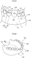
- the denture base 100 can be obtained by a cutting step of cutting the denture base material as described above or by a 3D printing step as described above. All the artificial teeth 200 are fixedly attached by an attachment step of attaching the artificial teeth 200 to the sockets 120 of the denture base 100, whereby the denture 300 shown in FIG. 6 is manufactured.
- the basal surfaces 230 of the artificial teeth 200 are fixed to the basal surfaces 130 of the sockets 120 and are attached in a state in which the alveolar ridge R of the maxilla is made to fit into a concave portion 104 of the base portion 102 of the denture base 100.
- the lower end edges 208 of both the labial-side surfaces 204 and the lingual-side surfaces 206 of the artificial teeth 200 are not embedded in the gingival area 110 and are visible from the outside.
- sockets 520 are recessed as in a conventional example as in a denture 700 of a comparative example shown in FIG. 7B , it is apparent that a base portion 502 of a denture base 500 must be reduced in thickness by that amount.
- the alveolar ridge R is high, in order to ensure that root portions 630 of artificial teeth 600 do not abut the alveolar ridge R, it is necessary to make the base portion 502 thicker and cut by that amount the root portions 630 where the artificial teeth 600 are to be fixed to the sockets 520.
- the fixing degree between the artificial teeth 600 and the sockets 520 may become insufficient.
- each of the sockets 120 is formed in a convex shape and the artificial teeth 200 are placed on and fixed to the sockets 120, so even when the alveolar ridge R is high, it is not necessary to cut the areas where the artificial teeth 200 are to be fixed to the sockets 120.
- a denture base whose manufacturing burden can be reduced, and a denture equipped with the denture base and an artificial tooth embedded therein.
- the thickness of the denture base does not need to be reduced and collar portions of the artificial teeth do not need to be cut beforehand.
- the areas where the artificial teeth are to be embedded in the denture base are small, so the step of cutting the artificial teeth even in a denture for a patient with a high alveolar ridge can be significantly reduced or eliminated.
- the area of adhesion to the artificial teeth is increased because each of the basal surfaces of the denture base has a convex shape, and the fixing force of the artificial teeth can be raised.
- the attachment step is also a step of adhering the artificial teeth 200 to the denture base 100, that is, an adhesion step.
- the adhesive (resin) for adhering the artificial teeth 200 to the denture base 100 for example, acrylic resin can be used.
- the acrylic resin is not particularly limited as long as it is capable of principal adhesion between the denture base 100 and the artificial teeth 200, and commercially available products may be used. That is, it is preferred that the adhesion step be a step (hereinafter referred to as a "principal adhesion step") of principally adhering the artificial teeth 200 to the denture base 100 using acrylic resin.
- principal adhesion between the denture base 100 and the artificial teeth 200 means that the artificial teeth 200 are fixedly attached to the denture base 100 to an extent that the denture base 100 and the artificial teeth 200 are capable of being used as the denture 300.
- acrylic resin used in the principal adhesion step examples include resin that is polymerized at a normal temperature (0 °C to 35 °C), resin that is polymerized by heat, and resin that is polymerized by light.
- resin that is polymerized at a normal temperature (0 °C to 35 °C) or the resin that is polymerized by heat examples include acrylic resin whose polymerization progresses at a relatively low temperature (0 °C to 70 °C) and acrylic resin whose polymerization progresses at 70 °C or higher.
- acrylic resin whose polymerization progresses at a relatively low temperature preferably 0 °C to 70 °C
- specific acrylic resin is referred to as "specific acrylic resin.”
- an acrylic resin comprising a mixture of a polymer powder and a monomer solution may be used.
- the acrylic resin When injecting the acrylic resin into the interstices between the sockets 120 and the artificial teeth 200, injection is easy if the acrylic resin is in a lowviscosity state just after mixing.
- the polymer powder include acrylic resin such as polymethyl methacrylate
- examples of the monomer solution include esters of methacrylic acid such as methyl methacrylate and ethyl methacrylate.
- the acrylic resin may also include other components such as, for example, a diffusion-promoting monomer such as 4-META (4-methacryloxyethyl trimellitate anhydride), a normaltemperature polymerization initiator (or a thermal polymerization initiator) such as TBB (trin-butylborane), a polymerization inhibitor, and a colorant.
- a diffusion-promoting monomer such as 4-META (4-methacryloxyethyl trimellitate anhydride)
- a normaltemperature polymerization initiator or a thermal polymerization initiator
- TBB trin-butylborane
- acrylic resin examples include ACRON (manufactured by GC Corporation), PalaXpress ultra (manufactured by Heraeus Kulzer), and Re-fine Bright manufactured by Hyundaichi Dental Mfg., Co.
- the adhesion step may also include a step (hereinafter also referred to as a "preliminary adhesion step") of preliminarily adhering the artificial teeth 200 to the denture base 100.
- preliminary adhesion means attaching the artificial teeth to the denture base to the extent that the positional relationship between the artificial teeth 200 and the denture base 100 is maintained, and being able to modify the positional relationship or easily cancel the state of adhesion as needed.
- Examples of methods of preliminary adhering the artificial teeth 200 to the denture base 100 include a method where dental composite resin or acrylic resin is used, the resin (dental composite resin or acrylic resin) is injected into the interstices between the artificial teeth 200 and at least some of the sockets 120, and the injected resin is polymerized at a normal temperature (0 °C to 35 °C), polymerized by heat, or polymerized by light (e.g., visible light).
- Examples of the resin used in the preliminary adhesion step include dental composite resin or acrylic resin.
- Examples of the acrylic resin used in the preliminary adhesion step include the same examples as those for the acrylic resin used in the principal adhesion step, but among them the specific acrylic resin (acrylic resin whose polymerization progresses at a relatively low temperature (preferably 0 °C to 70 °C)) is preferred.
- the dental composite resin will be described later.
- the adhesion step has the preliminary adhesion step
- removal of those artificial teeth 200 can be performed.
- the preliminary adhesion step be a step of preliminarily adhering the artificial teeth 200 to at least some of the sockets 120 of the denture base 100 from the viewpoint of more appropriately adjusting the amount of resin used in the principal adhesion.
- the dental composite resin is not particularly limited as long as it can preliminarily adhere the artificial teeth 200 and the denture base 100 to each other; for example, a composite resin (restorative material) such as a mold restorative material, a crown prosthesis material, or a dental filler, or a self-adhesive cement can be used.
- a composite resin restorative material
- a mold restorative material such as a mold restorative material, a crown prosthesis material, or a dental filler, or a self-adhesive cement
- the composite resin may include, for example, dimethacrylate as a matrix resin and also include an inorganic filler, a silane coupling agent, and so forth.
- dimethacrylate include bisphenol A-glycidyl methacrylate (Bis-GMA), triethylene glycol dimethacrylate (TEGDMA), and urethane dimethacrylate (UDMA).
- the self-adhesive cement may include polymethyl methacrylate (PMMA) or the aforementioned dimethacrylate as a matrix resin and may also include an adhesive substance, a filler, and so forth.
- PMMA polymethyl methacrylate
- dimethacrylate dimethacrylate
- examples of the composite resin include flowable types that have a low viscosity and a low elasticity and paste types that have a high viscosity and a high elasticity, but in view of the fact that each of the sockets 120 of the denture base 100 is configured by a surface that is convex overall, paste types that have a certain viscosity and elasticity are preferred.
- a photopolymerizable composite resin is preferred because it more appropriately enables positional adjustment of the artificial teeth 200.
- the composite resin that has been injected into the socket portions of the denture base is not cured before being exposed to light, so handling is excellent and it is easy to perform positional adjustment of the artificial teeth with good precision.
- the adhesive strength of the adhesion (preliminary adhesion) after curing is relatively weak, so the artificial teeth 200 can be easily removed from the denture base 100, and after the artificial teeth 200 are removed it is easy to apply the composite resin to the sockets 120 of the denture base 100 and re-adhere (preliminarily adhere) the artificial teeth 200 to the denture base 100.
- the artificial teeth 200 can be easily removed from the denture base 100 even after curing, so it is easy to perform positional adjustment by re-adhering (preliminarily adhering) the artificial teeth 200.
- the photopolymerizable composite resin may include, for example, a polymerizable compound such as an ester of acrylic acid or an ester of methacrylic acid, an inorganic filler, and a photopolymerization initiator, and may further include a polymerization accelerator.
- Examples of commercially available composite resin include Beautifil II (manufactured by Shofu Inc.) and Revotek (manufactured by GC Corporation).
- the artificial teeth 200 Before attaching the artificial teeth 200 to the denture base 100 with the adhesive in the attachment step (adhesion step), the artificial teeth 200 may also be temporarily fixed to the denture base 100 using a temporary fixing material. This temporary fixing also temporarily fixes the artificial teeth 200 to the denture base 100 to the extent that the positional relationship between the artificial teeth 200 and the denture base 100 is maintained. After the temporary fixing, the principal adhesion may be performed, without the preliminary adhesion being performed, as the attachment step.
- an adhesive material that deforms at 25 °C (normal temperature), for example, can be used as the temporary fixing material.
- the adhesive material include resin such as urethane resins, acrylic resins, silicone resins, vinyl chloride resins, vinyl alcohol resins, vinyl alkyl ether resins, or acrylamide resins, and rubber such as natural rubber, silicone rubber, or styrene-butadiene copolymer elastomer.
- putty e.g., model putty, dental putty
- tack label e.g., wheat flour clay, and adhesive metal foil tape, for example, may also be used as the adhesive material.
- Putty is a material used to fill depressions, cracks, and holes.
- Putty usually includes a pigment, a resin (a non-volatile vehicle), and a volatile substance.
- putty examples include one-component (one-part) or multi-component (two-part, etc.) putty such as epoxy putty, polyester putty, silicone putty, or a modified putty of these, lacquer putty, instant adhesive putty, gypsum putty, calcium carbonate putty, or photocurable putty.
- Tack label is a label where an adhesive material is provided on the back side of a base material, and is used by disposing the side with the adhesive material on the place to be temporarily fixed (e.g., near the boundary between the tooth crown and the tooth root).
- the material for the base material is not particularly limited.
- Examples of the pressure-sensitive adhesive material provided on the back side of the base material include the above-mentioned resins and the above-mentioned rubbers.
- metal foil tape known adhesive metal foil tapes can be used.
- dental putty is more preferred, and dental silicone putty is even more preferred.
- dental putty preferably dental silicone putty
- there is little reversion during deformation so positional adjustment of the artificial teeth 200 can be easily performed.
- the positional relationship between the artificial teeth 200 and the denture base 100 during temporary fixing is easily maintained.
- one type may be used by itself or two or more types may be used in combination.
- the shape of the temporary fixing material is not particularly limited as long as it is a shape by which the artificial teeth 200 can be temporarily fixed to the denture base, and a variety of shapes can be employed.
- the basal surface 130 of the socket 120 of the denture base 100 is configured by a surface that is convex overall
- the basal surface 230 of the artificial tooth 200 is configured as a surface that is concave overall
- the "surface that is convex overall" in relation to the basal surface 130 of the socket 120 also includes a surface where there is a concave shape such as the recessed portion 160 in part of the basal surface 130 of the socket 120 as shown in FIG. 16 .
- the "surface that is concave overall” in relation to the basal surface 230 of the artificial tooth 200 also includes a surface where there is a convex shape such as the projecting portion 240 in part of the basal surface 230 of the artificial tooth 200 as shown in FIG. 16 .
- the projecting portion 240 that forms parts of the basal surface 230 of the artificial tooth 200 is configured as a protrusion that is hidden from both the labial-side surface 204 and the lingual-side surface 206 of the artificial tooth 200.
- the recessed portion 160 that forms part of the basal surface 130 of the socket 120 of the denture base 100 is configured as a recess with which the projecting portion 240 that forms part of the basal surface 230 of the artificial tooth 200 mates.
- the projecting portion 240 of the artificial tooth 200 has a size that does not extend beyond straight line d that passes through the lower end edge 208 of the labial-side surface 204 and the lower end edge 208 of the lingual-side surface 206 of the artificial tooth 200 when the artificial tooth 200 is attached to the denture base 100.
- the recessed portion 160 of the basal surface 130 of the socket 120 has a size that does not extend beyond straight line d that passes through the lower end edge 208 of the labial-side surface 204 and the lower end edge 208 of the lingual-side surface 206 of the artificial tooth 200 when the artificial tooth 200 is attached to the denture base 100.
- Two or more of the recessed portions 160 may also be provided in the basal surface 130 of the socket 120, and two or more of the projecting portions 240 may also be provided in the basal surface 230 of the artificial tooth 200.
- all the recessed portions 160 and all the projecting portions 240 have a size that does not extend beyond straight line d that passes through the lower end edge 208 of the labial-side surface 204 and the lower end edge 208 of the lingual-side surface 206 of the artificial tooth 200 when the artificial tooth 200 is attached to the denture base 100.
- the recessed portion 160 described above is not necessarily provided in the basal surface 130 of the socket 120 of the denture base 100, and the projecting portion 240 described above is not necessarily provided in the basal surface 230 of the artificial tooth 200.
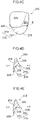
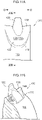
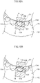
- the denture 300 of a second embodiment is the same in terms of its configuration, material, and method of manufacture as the denture 300 of the first embodiment except that, as shown in FIG. 8A and FIG. 8B , a protruding portion 122 projects from the socket apex portion 138 of the basal surface 130 of the socket 120 of the denture base 100 and, as shown in FIG. 9A and FIG. 9B , a recessed portion 202 corresponding to the protruding portion 122 is provided in the basal surface apex portion 238 of the basal surface 230 of the artificial tooth 200.
- the protruding portion 122 of the denture base 100 is fitted into the recessed portion 202 of the artificial tooth 200 and, as in the first embodiment, the basal surface 130 of the socket 120 and the basal surface 230 of the artificial tooth 200 are adhered to each other.
- the protruding portion 122 of the denture base 100 mates with the recessed portion 202 of the artificial tooth 200 as shown in the sectional view of FIG. 10 . Due to this mating, the fixing degree of the artificial tooth 200 with respect to the denture base 100 is enhanced. Other points are the same as those of the denture 300 of the first embodiment.
- the denture 300 of a third embodiment is the same as that of the second embodiment in that, as shown in FIG. 11A and FIG. 11B , the protruding portion 122 projects from the socket apex portion 138 of the basal surface 130 of the socket 120 of the denture base 100 and, as shown in FIG. 12A and FIG. 12B , the recessed portion 202 corresponding to the protruding portion 122 is provided in the basal surface apex portion 238 of the basal surface 230 of the artificial tooth 200.
- a cutout portion 210 is provided in the center portion of the lingual-side surface 206.
- FIG. 11B the protruding portion 122 projects from the socket apex portion 138 of the basal surface 130 of the socket 120 of the denture base 100 and, as shown in FIG. 12A and FIG. 12B , the recessed portion 202 corresponding to the protruding portion 122 is provided in the basal surface apex portion 238 of the basal surface 230 of the artificial tooth
- a raised portion 140 that mates with the cutout portion 210 is formed in the basal surface 134 on the lingual surface side of the denture base 100.
- the configuration, material, and method of manufacture are the same as those of the denture 300 of the first embodiment.
- the protruding portion 122 of the denture base 100 is fitted into the recessed portion 202 of the artificial tooth 200, the raised portion 140 of the artificial tooth 100 is simultaneously fitted into the cutout portion 210 of the artificial tooth 200, and, as in the first embodiment, the basal surface 130 of the socket 120 and the basal surface 230 of the artificial tooth 200 are adhered to each other.
- the protruding portion 122 of the denture base 100 mates with the recessed portion 202 of the artificial tooth 200, and the raised portion 140 of the denture base 100 mates with the cutout portion 210 of the artificial tooth 200. Due to this mating, the fixing degree of the artificial tooth 200 with respect to the denture base 100 is further enhanced. Other points are the same as those of the denture 300 of the first embodiment.
- the denture 300 pertaining to a fourth embodiment is a partial denture as shown in FIG. 14 .
- the artificial tooth 200 is attached to a socket (not shown) of the denture base 100.
- the lower end edge 208 of the labial-side surface 204 (and that of the lingual-side surface not shown in the drawing) of the artificial tooth 200 is visible from the outside in a state in which it is flush with the gingival area 110.
- Clasps 150 for allowing the denture 300 to clasp onto adjacent natural teeth are provided on both ends of the artificial tooth 200 along the tooth row.
- the present invention is applicable to a denture base, and a denture comprising a combination of the denture base and an artificial Z tooth.
Claims (9)
- Zahnersatzbasis (100), umfassend:einen Basisabschnitt (102);ein Zahnfach (120), das durch einen Stufenabschnitt (112) von einem Zahnfleischbereich (110) des Basisabschnitts (102) abgegrenzt ist und an dem ein künstlicher Zahn (200) zu befestigen ist; undInterdentalpapillenbereiche (114) des Zahnfleischbereichs (110), die an beiden Enden des Zahnfachs (120) entlang einer Zahnreihe positioniert sind und die Interdentalpapillen zwischen benachbarten Zähnen entsprechen,wobei in einem Zustand, in dem das Zahnfach (120) nach oben gerichtet ist:eine Basalfläche (130) des Zahnfachs (120) einen rippenförmigen Zahnfachspitzenabschnitt (138) aufweist, der die Interdentalpapillenbereiche (114) an beiden Enden miteinander verbindet und durch eine insgesamt konvexe Oberfläche gestaltet ist,ein Umfangsbereich (136) der Basalfläche (130) in gegenseitigem kontinuierlichem Abutment mit dem Stufenabschnitt (112) steht, unddadurch gekennzeichnet, dass der Zahnfachspitzenabschnitt (138) im Wesentlichen so hoch wie oder höher als Spitzenabschnitte (116) der Interdentalpapillenbereiche (114) angeordnet ist, die von einer labialen Seite in einem Zustand gesehen werden, in dem der künstliche Zahn (200) an dem Zahnfach (120) befestigt ist.
- Zahnersatzbasis (100) gemäß Anspruch 1, wobei die Basalfläche (130) an einer labialen Oberflächenseite des Zahnfachspitzenabschnitts (138) in einer konvexen Form ausgebildet ist, die sich zur labialen Seite hin nach unten neigt.
- Zahnersatzbasis (100) gemäß Anspruch 2, wobei die Basalfläche (130) an einer lingualen Oberflächenseite des Zahnfachspitzenabschnitts (138) ebenfalls in einer konvexen Form ausgebildet ist, die sich zur lingualen Seite hin nach unten neigt.
- Zahnersatzbasis (100) gemäß Anspruch 3, ferner umfassend einen vorstehenden Abschnitt (122) in der Basalfläche (130), der von dem Zahnfachspitzenabschnitt (138) nach oben vorsteht.
- Zahnersatzbasis (100) gemäß einem der Ansprüche 1 bis 4, wobei:eine Mehrzahl von Zahnfächern (120) nebeneinander in dem Basisabschnitt (102) ausgebildet sind, undein Zahnfach (120) mit der Basalfläche (130) mindestens eines der Mehrzahl von Zahnfächern (120) ist.
- Verfahren zur Herstellung einer Zahnersatzbasis (100), umfassend einen Schneideschritt des Schneidens eines Zahnersatzbasis (100)-Materials, um die Zahnersatzbasis (100) gemäß einem der Ansprüche 1 bis 5 zu erhalten.
- Verfahren zur Herstellung einer Zahnersatzbasis (100) gemäß Anspruch 6, wobei der Schneideschritt einen Schritt (einen CAD/CAM-Schritt) des Verwendens einer CAM-Systemeinheit umfasst, um ein Design herzustellen, das von einer CAD-Systemeinheit entworfen wurde.
- Zahnersatz, umfassend eine Zahnersatzbasis (100) und einen künstlichen Zahn (200), der an einem Zahnfach (120) der Zahnersatzbasis (100) befestigt ist, wobei die Zahnersatzbasis (100) umfasst:einen Basisabschnitt (102);ein Zahnfach (120), das durch einen Stufenabschnitt (112) von einem Zahnfleischbereich (110) des Basisabschnitts (102) abgegrenzt ist und an dem ein künstlicher Zahn (200) zu befestigen ist; undInterdentalpapillenbereiche (114) des Zahnfleischbereichs (110), die an beiden Enden des Zahnfachs (120) entlang einer Zahnreihe positioniert sind und die Interdentalpapillen zwischen benachbarten Zähnen entsprechen,wobei in einem Zustand, in dem das Zahnfach (120) nach oben gerichtet ist:eine Basalfläche (130) des Zahnfachs (120) einen rippenförmigen Zahnfachspitzenabschnitt (138) aufweist, der die Interdentalpapillenbereiche (114) an beiden Enden miteinander verbindet und durch eine insgesamt konvexe Oberfläche gestaltet ist,ein Umfangsbereich (136) der Basalfläche (130) in gegenseitigem kontinuierlichem Abutment mit dem Stufenabschnitt (112) steht, undder Zahnfachspitzenabschnitt (138) im Wesentlichen so hoch wie oder höher als Spitzenabschnitte (116) der Interdentalpapillenbereiche (114) angeordnet ist, die von einer labialen Seite in einem Zustand gesehen werden, in dem der künstliche Zahn (200) an dem Zahnfach (120) befestigt ist; undwobei der künstliche Zahn (200) umfasst:eine Basalfläche (230), die an einem Zahnfach (120) einer Zahnersatzbasis (100) zu befestigen ist, mit einem talförmigen Basalflächenspitzenabschnitt (238), der beide Enden des künstlichen Zahns (200) entlang einer Zahnreihe miteinander verbindet und durch eine Oberfläche gestaltet ist, die insgesamt konkav ist, wenn eine Okklusionsfläche des künstlichen Zahns (200) nach oben gerichtet ist; undjeweils eine labialseitige Oberfläche (204) und eine lingualseitige Oberfläche (206) als durchgehende Oberflächen ausgebildet sind, deren untere Endkante (208) auch nach dem Anbringen des künstlichen Zahns (200) an dem Zahnfach (120) sichtbar ist.
- Zahnersatz gemäß Anspruch 8, wobei:in dem Basisabschnitt (102) eine Mehrzahl von Zahnfächern (120) nebeneinander ausgebildet sind, undkünstliche Zähne (200), die an jedem der Zahnfächer (120) befestigt sind, miteinander verbunden sind.
Priority Applications (1)
| Application Number | Priority Date | Filing Date | Title |
|---|---|---|---|
| EP21190524.5A EP3925570A1 (de) | 2017-02-28 | 2018-02-23 | Künstlicher zahn |
Applications Claiming Priority (2)
| Application Number | Priority Date | Filing Date | Title |
|---|---|---|---|
| JP2017037173 | 2017-02-28 | ||
| PCT/JP2018/006809 WO2018159507A1 (ja) | 2017-02-28 | 2018-02-23 | 義歯床及びその製造方法、人工歯及びその製造方法並びに有床義歯及びその製造方法 |
Related Child Applications (2)
| Application Number | Title | Priority Date | Filing Date |
|---|---|---|---|
| EP21190524.5A Division EP3925570A1 (de) | 2017-02-28 | 2018-02-23 | Künstlicher zahn |
| EP21190524.5A Division-Into EP3925570A1 (de) | 2017-02-28 | 2018-02-23 | Künstlicher zahn |
Publications (3)
| Publication Number | Publication Date |
|---|---|
| EP3586790A1 EP3586790A1 (de) | 2020-01-01 |
| EP3586790A4 EP3586790A4 (de) | 2021-03-03 |
| EP3586790B1 true EP3586790B1 (de) | 2022-06-29 |
Family
ID=63370835
Family Applications (2)
| Application Number | Title | Priority Date | Filing Date |
|---|---|---|---|
| EP21190524.5A Withdrawn EP3925570A1 (de) | 2017-02-28 | 2018-02-23 | Künstlicher zahn |
| EP18761121.5A Active EP3586790B1 (de) | 2017-02-28 | 2018-02-23 | Zahnersatzplatte und verfahren zur herstellung davon, plattenzahnersatz und verfahren zur herstellung davon |
Family Applications Before (1)
| Application Number | Title | Priority Date | Filing Date |
|---|---|---|---|
| EP21190524.5A Withdrawn EP3925570A1 (de) | 2017-02-28 | 2018-02-23 | Künstlicher zahn |
Country Status (6)
| Country | Link |
|---|---|
| US (2) | US20190388198A1 (de) |
| EP (2) | EP3925570A1 (de) |
| JP (1) | JP6781816B2 (de) |
| KR (1) | KR102351897B1 (de) |
| CN (1) | CN110312490B (de) |
| WO (1) | WO2018159507A1 (de) |
Families Citing this family (11)
| Publication number | Priority date | Publication date | Assignee | Title |
|---|---|---|---|---|
| US11660173B2 (en) * | 2019-02-15 | 2023-05-30 | Dentsply Sirona Inc. | Denture base and dental prosthesis |
| GB2581491B (en) * | 2019-02-18 | 2023-02-22 | Davis Schottlander & Davis Ltd | Prosthetic tooth |
| ES2843551A1 (es) * | 2020-01-17 | 2021-07-19 | Laboratorio Digital High Teeth S L | Procedimiento de fabricación de prótesis dentales y prótesis dental |
| GB2593449A (en) * | 2020-03-13 | 2021-09-29 | Davis Schottlander & Davis Ltd | Prosthetic tooth or denture base |
| CN111759507A (zh) * | 2020-07-08 | 2020-10-13 | 秦皇岛泽克尼陶瓷科技有限公司 | 一种微创美学支架义齿及其制备方法 |
| CN111888022B (zh) * | 2020-08-11 | 2021-12-14 | 泰安市东方义齿有限公司 | 一种义齿的一次成型制造方法 |
| DE102021112178B4 (de) * | 2021-05-10 | 2023-01-12 | Kulzer Gmbh | Verfahren und Vorrichtung zur Herstellung einer Dentalprothese |
| WO2023042915A1 (ja) * | 2021-09-17 | 2023-03-23 | クラレノリタケデンタル株式会社 | 光造形用有床義歯作製キット、及び有床義歯の製造方法 |
| CN117915858A (zh) * | 2021-10-26 | 2024-04-19 | 德山齿科株式会社 | 义齿用铣削坯件、前牙用被切削加工部件及义齿的制造方法 |
| US20230301760A1 (en) | 2022-03-23 | 2023-09-28 | Kabushiki Kaisha Shofu | Denture base and manufacturing method for the same |
| KR20240043580A (ko) | 2022-09-27 | 2024-04-03 | 성균관대학교산학협력단 | 탈부착식 플렉시블 의치 및 이의 제조 방법 |
Family Cites Families (23)
| Publication number | Priority date | Publication date | Assignee | Title |
|---|---|---|---|---|
| ATE281126T1 (de) * | 1996-05-17 | 2004-11-15 | Brandestini Marco | Verfahren zur herstellung dentaler rekonstruktionen und rohling zur durchführung des verfahrens |
| AU7937698A (en) * | 1997-07-10 | 1998-11-27 | Hideyo Uji | Artificial tooth |
| JP3064138U (ja) | 1999-05-20 | 1999-12-24 | 株式会社ジーシーデンタルプロダクツ | 人工歯 |
| JP2001095820A (ja) * | 1999-09-29 | 2001-04-10 | Kazuo Komine | 有床義歯およびその製造方法 |
| DE10304757B4 (de) * | 2003-02-05 | 2005-07-21 | Heraeus Kulzer Gmbh | Vorrichtung und Verfahren zur Herstellung von Zahnersatz |
| EP1454597A1 (de) * | 2003-03-04 | 2004-09-08 | Merz Dental GmbH | Kunstzahn für Zahnprothesen |
| JP2007000324A (ja) * | 2005-06-23 | 2007-01-11 | Oyama Yoshio | 義歯及びその製造方法 |
| JP2008168065A (ja) * | 2007-01-15 | 2008-07-24 | Yunikkusu Japan:Kk | 有床義歯 |
| WO2008129673A1 (ja) * | 2007-04-18 | 2008-10-30 | Kabushiki Kaisha Shofu | 人工歯 |
| JP2008289839A (ja) * | 2007-05-28 | 2008-12-04 | Yukinori Shimada | 人工歯の基底面と床を重着接合する構造方式の義歯 |
| DE102007031229A1 (de) * | 2007-07-04 | 2009-01-08 | Schäfer, Günter Willy | Dentalprothese |
| CN101815480B (zh) * | 2007-10-01 | 2013-05-01 | 株式会社松风 | 易于两侧平衡咬合的人造牙 |
| JP5610394B2 (ja) * | 2008-11-20 | 2014-10-22 | 国立大学法人 東京医科歯科大学 | 有床義歯及びその製造方法 |
| CN101862225A (zh) * | 2009-04-20 | 2010-10-20 | 涂本洲 | 一种半成品全口义齿及制造方法 |
| JP4869394B2 (ja) * | 2009-10-19 | 2012-02-08 | 株式会社ユニックスジャパン | 義歯 |
| JP5693903B2 (ja) * | 2010-09-30 | 2015-04-01 | 株式会社シケン | 有床義歯とこれに使用される人工歯 |
| DK2742906T3 (en) * | 2012-12-17 | 2016-10-03 | Ivoclar Vivadent Ag | A method and system for the construction of a dental prosthesis. |
| US10357435B2 (en) * | 2012-12-18 | 2019-07-23 | Dentca, Inc. | Photo-curable resin compositions and method of using the same in three-dimensional printing for manufacturing artificial teeth and denture base |
| ES2792224T3 (es) * | 2013-04-18 | 2020-11-10 | Dentca Inc | Composiciones de resina fotocurable y método de utilización de las mismas en impresión tridimensional para fabricar dientes artificiales y base de dentadura postiza |
| DE102014118231B3 (de) * | 2014-12-09 | 2016-05-12 | Heraeus Kulzer Gmbh | Verfahren zur Herstellung einer Dentalprothese mit einer Schablone |
| DE102015100080B3 (de) * | 2015-01-07 | 2016-05-12 | Heraeus Kulzer Gmbh | Verfahren zur Herstellung einer Dentalprothese |
| DE102015104394B4 (de) * | 2015-03-24 | 2020-06-04 | Kulzer Gmbh | Verfahren zur Herstellung einer Teil- oder Totalprothese sowie Prothese erhältlich nach diesem Verfahren |
| JP6815068B2 (ja) * | 2015-07-09 | 2021-01-20 | 三井化学株式会社 | 義歯床、有床義歯、義歯床の製造方法および有床義歯の製造方法 |
-
2018
- 2018-02-23 WO PCT/JP2018/006809 patent/WO2018159507A1/ja unknown
- 2018-02-23 EP EP21190524.5A patent/EP3925570A1/de not_active Withdrawn
- 2018-02-23 US US16/483,927 patent/US20190388198A1/en not_active Abandoned
- 2018-02-23 JP JP2019502966A patent/JP6781816B2/ja active Active
- 2018-02-23 EP EP18761121.5A patent/EP3586790B1/de active Active
- 2018-02-23 CN CN201880012470.6A patent/CN110312490B/zh active Active
- 2018-02-23 KR KR1020197022696A patent/KR102351897B1/ko active IP Right Grant
-
2023
- 2023-02-13 US US18/168,075 patent/US20230190426A1/en active Pending
Also Published As
| Publication number | Publication date |
|---|---|
| EP3586790A1 (de) | 2020-01-01 |
| CN110312490B (zh) | 2021-11-09 |
| JP6781816B2 (ja) | 2020-11-04 |
| US20190388198A1 (en) | 2019-12-26 |
| WO2018159507A1 (ja) | 2018-09-07 |
| US20230190426A1 (en) | 2023-06-22 |
| KR102351897B1 (ko) | 2022-01-14 |
| CN110312490A (zh) | 2019-10-08 |
| KR20190103288A (ko) | 2019-09-04 |
| JPWO2018159507A1 (ja) | 2019-12-12 |
| EP3925570A1 (de) | 2021-12-22 |
| EP3586790A4 (de) | 2021-03-03 |
Similar Documents
| Publication | Publication Date | Title |
|---|---|---|
| EP3586790B1 (de) | Zahnersatzplatte und verfahren zur herstellung davon, plattenzahnersatz und verfahren zur herstellung davon | |
| US10835354B2 (en) | System and method for registering implant orientation directly from a dental impression | |
| US7217131B2 (en) | Method for dental restoration and kit | |
| US8753114B2 (en) | Method for dental restoration and related kit | |
| US6884073B2 (en) | Temporary and semi-permanent dental crowns | |
| US8308478B2 (en) | Methods for indirect bonding of orthodontic appliances | |
| US8366445B2 (en) | Method for dental restoration and related kit | |
| US20100119992A1 (en) | Artificial tooth | |
| JPH01299547A (ja) | 臼歯部用人工歯及びその咬合面部を置換する方法 | |
| US20040161726A1 (en) | Crown prosthesis | |
| JP2007236465A (ja) | 多層人工歯用本体部材 | |
| JP7120506B2 (ja) | 義歯床、義歯床の製造方法、有床義歯及び有床義歯の製造方法 | |
| WO2016142407A1 (en) | Process for producing a denture | |
| US11793614B2 (en) | Method for producing denture with high accuracy of fitting of artificial tooth to socket | |
| US20040096805A1 (en) | Prosthesis for tooth surface | |
| JP2001149385A (ja) | 歯科用補綴物 | |
| KR20220072370A (ko) | 미리 성형되어 제공되는 변형 가능한 치아 모양의 보철물 및 그 제조방법 | |
| Sisler | Preparation guides: 10 steps to maximize success for veneer preparation | |
| US20040224284A1 (en) | Prosthesis like an artificial tooth for bridges | |
| Schäffer et al. | Complete restoration with resin-bonded porcelain inlays. | |
| KR102652030B1 (ko) | 디지털보철 및 그의 제조방법 | |
| JPH05192353A (ja) | 補綴義歯前駆体及び補綴義歯作成方法 | |
| AU697179B2 (en) | Tooth-veneer process | |
| JP3153933U (ja) | 連結人工歯 | |
| JPH05220178A (ja) | 義歯用材料 |
Legal Events
| Date | Code | Title | Description |
|---|---|---|---|
| STAA | Information on the status of an ep patent application or granted ep patent |
Free format text: STATUS: THE INTERNATIONAL PUBLICATION HAS BEEN MADE |
|
| PUAI | Public reference made under article 153(3) epc to a published international application that has entered the european phase |
Free format text: ORIGINAL CODE: 0009012 |
|
| STAA | Information on the status of an ep patent application or granted ep patent |
Free format text: STATUS: REQUEST FOR EXAMINATION WAS MADE |
|
| 17P | Request for examination filed |
Effective date: 20190924 |
|
| AK | Designated contracting states |
Kind code of ref document: A1 Designated state(s): AL AT BE BG CH CY CZ DE DK EE ES FI FR GB GR HR HU IE IS IT LI LT LU LV MC MK MT NL NO PL PT RO RS SE SI SK SM TR |
|
| AX | Request for extension of the european patent |
Extension state: BA ME |
|
| DAV | Request for validation of the european patent (deleted) | ||
| DAX | Request for extension of the european patent (deleted) | ||
| RIC1 | Information provided on ipc code assigned before grant |
Ipc: A61C 13/01 20060101ALI20201014BHEP Ipc: A61C 13/087 20060101ALI20201014BHEP Ipc: A61C 13/007 20060101AFI20201014BHEP Ipc: A61C 13/00 20060101ALI20201014BHEP Ipc: A61C 13/103 20060101ALI20201014BHEP Ipc: A61C 13/08 20060101ALI20201014BHEP Ipc: A61C 13/093 20060101ALI20201014BHEP |
|
| A4 | Supplementary search report drawn up and despatched |
Effective date: 20210201 |
|
| RIC1 | Information provided on ipc code assigned before grant |
Ipc: A61C 13/103 20060101ALI20210126BHEP Ipc: A61C 13/08 20060101ALI20210126BHEP Ipc: A61C 13/087 20060101ALI20210126BHEP Ipc: A61C 13/01 20060101ALI20210126BHEP Ipc: A61C 13/007 20060101AFI20210126BHEP Ipc: A61C 13/00 20060101ALI20210126BHEP Ipc: A61C 13/093 20060101ALI20210126BHEP |
|
| GRAP | Despatch of communication of intention to grant a patent |
Free format text: ORIGINAL CODE: EPIDOSNIGR1 |
|
| STAA | Information on the status of an ep patent application or granted ep patent |
Free format text: STATUS: GRANT OF PATENT IS INTENDED |
|
| INTG | Intention to grant announced |
Effective date: 20220202 |
|
| GRAS | Grant fee paid |
Free format text: ORIGINAL CODE: EPIDOSNIGR3 |
|
| GRAA | (expected) grant |
Free format text: ORIGINAL CODE: 0009210 |
|
| STAA | Information on the status of an ep patent application or granted ep patent |
Free format text: STATUS: THE PATENT HAS BEEN GRANTED |
|
| AK | Designated contracting states |
Kind code of ref document: B1 Designated state(s): AL AT BE BG CH CY CZ DE DK EE ES FI FR GB GR HR HU IE IS IT LI LT LU LV MC MK MT NL NO PL PT RO RS SE SI SK SM TR |
|
| REG | Reference to a national code |
Ref country code: CH Ref legal event code: EP |
|
| REG | Reference to a national code |
Ref country code: AT Ref legal event code: REF Ref document number: 1500795 Country of ref document: AT Kind code of ref document: T Effective date: 20220715 |
|
| REG | Reference to a national code |
Ref country code: IE Ref legal event code: FG4D |
|
| REG | Reference to a national code |
Ref country code: DE Ref legal event code: R096 Ref document number: 602018037353 Country of ref document: DE |
|
| REG | Reference to a national code |
Ref country code: LT Ref legal event code: MG9D |
|
| PG25 | Lapsed in a contracting state [announced via postgrant information from national office to epo] |
Ref country code: SE Free format text: LAPSE BECAUSE OF FAILURE TO SUBMIT A TRANSLATION OF THE DESCRIPTION OR TO PAY THE FEE WITHIN THE PRESCRIBED TIME-LIMIT Effective date: 20220629 Ref country code: NO Free format text: LAPSE BECAUSE OF FAILURE TO SUBMIT A TRANSLATION OF THE DESCRIPTION OR TO PAY THE FEE WITHIN THE PRESCRIBED TIME-LIMIT Effective date: 20220929 Ref country code: LT Free format text: LAPSE BECAUSE OF FAILURE TO SUBMIT A TRANSLATION OF THE DESCRIPTION OR TO PAY THE FEE WITHIN THE PRESCRIBED TIME-LIMIT Effective date: 20220629 Ref country code: HR Free format text: LAPSE BECAUSE OF FAILURE TO SUBMIT A TRANSLATION OF THE DESCRIPTION OR TO PAY THE FEE WITHIN THE PRESCRIBED TIME-LIMIT Effective date: 20220629 Ref country code: GR Free format text: LAPSE BECAUSE OF FAILURE TO SUBMIT A TRANSLATION OF THE DESCRIPTION OR TO PAY THE FEE WITHIN THE PRESCRIBED TIME-LIMIT Effective date: 20220930 Ref country code: FI Free format text: LAPSE BECAUSE OF FAILURE TO SUBMIT A TRANSLATION OF THE DESCRIPTION OR TO PAY THE FEE WITHIN THE PRESCRIBED TIME-LIMIT Effective date: 20220629 Ref country code: BG Free format text: LAPSE BECAUSE OF FAILURE TO SUBMIT A TRANSLATION OF THE DESCRIPTION OR TO PAY THE FEE WITHIN THE PRESCRIBED TIME-LIMIT Effective date: 20220929 |
|
| REG | Reference to a national code |
Ref country code: NL Ref legal event code: MP Effective date: 20220629 |
|
| REG | Reference to a national code |
Ref country code: AT Ref legal event code: MK05 Ref document number: 1500795 Country of ref document: AT Kind code of ref document: T Effective date: 20220629 |
|
| PG25 | Lapsed in a contracting state [announced via postgrant information from national office to epo] |
Ref country code: RS Free format text: LAPSE BECAUSE OF FAILURE TO SUBMIT A TRANSLATION OF THE DESCRIPTION OR TO PAY THE FEE WITHIN THE PRESCRIBED TIME-LIMIT Effective date: 20220629 Ref country code: LV Free format text: LAPSE BECAUSE OF FAILURE TO SUBMIT A TRANSLATION OF THE DESCRIPTION OR TO PAY THE FEE WITHIN THE PRESCRIBED TIME-LIMIT Effective date: 20220629 |
|
| PG25 | Lapsed in a contracting state [announced via postgrant information from national office to epo] |
Ref country code: NL Free format text: LAPSE BECAUSE OF FAILURE TO SUBMIT A TRANSLATION OF THE DESCRIPTION OR TO PAY THE FEE WITHIN THE PRESCRIBED TIME-LIMIT Effective date: 20220629 |
|
| PG25 | Lapsed in a contracting state [announced via postgrant information from national office to epo] |
Ref country code: SM Free format text: LAPSE BECAUSE OF FAILURE TO SUBMIT A TRANSLATION OF THE DESCRIPTION OR TO PAY THE FEE WITHIN THE PRESCRIBED TIME-LIMIT Effective date: 20220629 Ref country code: SK Free format text: LAPSE BECAUSE OF FAILURE TO SUBMIT A TRANSLATION OF THE DESCRIPTION OR TO PAY THE FEE WITHIN THE PRESCRIBED TIME-LIMIT Effective date: 20220629 Ref country code: RO Free format text: LAPSE BECAUSE OF FAILURE TO SUBMIT A TRANSLATION OF THE DESCRIPTION OR TO PAY THE FEE WITHIN THE PRESCRIBED TIME-LIMIT Effective date: 20220629 Ref country code: PT Free format text: LAPSE BECAUSE OF FAILURE TO SUBMIT A TRANSLATION OF THE DESCRIPTION OR TO PAY THE FEE WITHIN THE PRESCRIBED TIME-LIMIT Effective date: 20221031 Ref country code: ES Free format text: LAPSE BECAUSE OF FAILURE TO SUBMIT A TRANSLATION OF THE DESCRIPTION OR TO PAY THE FEE WITHIN THE PRESCRIBED TIME-LIMIT Effective date: 20220629 Ref country code: EE Free format text: LAPSE BECAUSE OF FAILURE TO SUBMIT A TRANSLATION OF THE DESCRIPTION OR TO PAY THE FEE WITHIN THE PRESCRIBED TIME-LIMIT Effective date: 20220629 Ref country code: AT Free format text: LAPSE BECAUSE OF FAILURE TO SUBMIT A TRANSLATION OF THE DESCRIPTION OR TO PAY THE FEE WITHIN THE PRESCRIBED TIME-LIMIT Effective date: 20220629 |
|
| PG25 | Lapsed in a contracting state [announced via postgrant information from national office to epo] |
Ref country code: PL Free format text: LAPSE BECAUSE OF FAILURE TO SUBMIT A TRANSLATION OF THE DESCRIPTION OR TO PAY THE FEE WITHIN THE PRESCRIBED TIME-LIMIT Effective date: 20220629 Ref country code: IS Free format text: LAPSE BECAUSE OF FAILURE TO SUBMIT A TRANSLATION OF THE DESCRIPTION OR TO PAY THE FEE WITHIN THE PRESCRIBED TIME-LIMIT Effective date: 20221029 |
|
| REG | Reference to a national code |
Ref country code: DE Ref legal event code: R097 Ref document number: 602018037353 Country of ref document: DE |
|
| PG25 | Lapsed in a contracting state [announced via postgrant information from national office to epo] |
Ref country code: AL Free format text: LAPSE BECAUSE OF FAILURE TO SUBMIT A TRANSLATION OF THE DESCRIPTION OR TO PAY THE FEE WITHIN THE PRESCRIBED TIME-LIMIT Effective date: 20220629 |
|
| PG25 | Lapsed in a contracting state [announced via postgrant information from national office to epo] |
Ref country code: DK Free format text: LAPSE BECAUSE OF FAILURE TO SUBMIT A TRANSLATION OF THE DESCRIPTION OR TO PAY THE FEE WITHIN THE PRESCRIBED TIME-LIMIT Effective date: 20220629 Ref country code: CZ Free format text: LAPSE BECAUSE OF FAILURE TO SUBMIT A TRANSLATION OF THE DESCRIPTION OR TO PAY THE FEE WITHIN THE PRESCRIBED TIME-LIMIT Effective date: 20220629 |
|
| RAP4 | Party data changed (patent owner data changed or rights of a patent transferred) |
Owner name: MITSUI CHEMICALS, INC. |
|
| PLBE | No opposition filed within time limit |
Free format text: ORIGINAL CODE: 0009261 |
|
| STAA | Information on the status of an ep patent application or granted ep patent |
Free format text: STATUS: NO OPPOSITION FILED WITHIN TIME LIMIT |
|
| PGFP | Annual fee paid to national office [announced via postgrant information from national office to epo] |
Ref country code: DE Payment date: 20230216 Year of fee payment: 6 |
|
| 26N | No opposition filed |
Effective date: 20230330 |
|
| PG25 | Lapsed in a contracting state [announced via postgrant information from national office to epo] |
Ref country code: SI Free format text: LAPSE BECAUSE OF FAILURE TO SUBMIT A TRANSLATION OF THE DESCRIPTION OR TO PAY THE FEE WITHIN THE PRESCRIBED TIME-LIMIT Effective date: 20220629 |
|
| PG25 | Lapsed in a contracting state [announced via postgrant information from national office to epo] |
Ref country code: MC Free format text: LAPSE BECAUSE OF FAILURE TO SUBMIT A TRANSLATION OF THE DESCRIPTION OR TO PAY THE FEE WITHIN THE PRESCRIBED TIME-LIMIT Effective date: 20220629 |
|
| REG | Reference to a national code |
Ref country code: CH Ref legal event code: PL |
|
| REG | Reference to a national code |
Ref country code: BE Ref legal event code: MM Effective date: 20230228 |
|
| GBPC | Gb: european patent ceased through non-payment of renewal fee |
Effective date: 20230223 |
|
| PG25 | Lapsed in a contracting state [announced via postgrant information from national office to epo] |
Ref country code: LU Free format text: LAPSE BECAUSE OF NON-PAYMENT OF DUE FEES Effective date: 20230223 Ref country code: LI Free format text: LAPSE BECAUSE OF NON-PAYMENT OF DUE FEES Effective date: 20230228 Ref country code: CH Free format text: LAPSE BECAUSE OF NON-PAYMENT OF DUE FEES Effective date: 20230228 |
|
| REG | Reference to a national code |
Ref country code: IE Ref legal event code: MM4A |
|
| PG25 | Lapsed in a contracting state [announced via postgrant information from national office to epo] |
Ref country code: GB Free format text: LAPSE BECAUSE OF NON-PAYMENT OF DUE FEES Effective date: 20230223 |
|
| PG25 | Lapsed in a contracting state [announced via postgrant information from national office to epo] |
Ref country code: IT Free format text: LAPSE BECAUSE OF FAILURE TO SUBMIT A TRANSLATION OF THE DESCRIPTION OR TO PAY THE FEE WITHIN THE PRESCRIBED TIME-LIMIT Effective date: 20220629 Ref country code: IE Free format text: LAPSE BECAUSE OF NON-PAYMENT OF DUE FEES Effective date: 20230223 Ref country code: GB Free format text: LAPSE BECAUSE OF NON-PAYMENT OF DUE FEES Effective date: 20230223 Ref country code: FR Free format text: LAPSE BECAUSE OF NON-PAYMENT OF DUE FEES Effective date: 20230228 |
|
| PG25 | Lapsed in a contracting state [announced via postgrant information from national office to epo] |
Ref country code: BE Free format text: LAPSE BECAUSE OF NON-PAYMENT OF DUE FEES Effective date: 20230228 |