EP3583890A2 - Magnetische messvorrichtung - Google Patents
Magnetische messvorrichtung Download PDFInfo
- Publication number
- EP3583890A2 EP3583890A2 EP19181528.1A EP19181528A EP3583890A2 EP 3583890 A2 EP3583890 A2 EP 3583890A2 EP 19181528 A EP19181528 A EP 19181528A EP 3583890 A2 EP3583890 A2 EP 3583890A2
- Authority
- EP
- European Patent Office
- Prior art keywords
- magnetic
- measurement device
- temperature
- magnetic object
- measurement
- Prior art date
- Legal status (The legal status is an assumption and is not a legal conclusion. Google has not performed a legal analysis and makes no representation as to the accuracy of the status listed.)
- Granted
Links
Images


Classifications
-
- G—PHYSICS
- G01—MEASURING; TESTING
- G01L—MEASURING FORCE, STRESS, TORQUE, WORK, MECHANICAL POWER, MECHANICAL EFFICIENCY, OR FLUID PRESSURE
- G01L19/00—Details of, or accessories for, apparatus for measuring steady or quasi-steady pressure of a fluent medium insofar as such details or accessories are not special to particular types of pressure gauges
- G01L19/14—Housings
-
- A—HUMAN NECESSITIES
- A61—MEDICAL OR VETERINARY SCIENCE; HYGIENE
- A61B—DIAGNOSIS; SURGERY; IDENTIFICATION
- A61B1/00—Instruments for performing medical examinations of the interior of cavities or tubes of the body by visual or photographical inspection, e.g. endoscopes; Illuminating arrangements therefor
- A61B1/00147—Holding or positioning arrangements
- A61B1/00158—Holding or positioning arrangements using magnetic field
-
- A—HUMAN NECESSITIES
- A61—MEDICAL OR VETERINARY SCIENCE; HYGIENE
- A61B—DIAGNOSIS; SURGERY; IDENTIFICATION
- A61B34/00—Computer-aided surgery; Manipulators or robots specially adapted for use in surgery
- A61B34/20—Surgical navigation systems; Devices for tracking or guiding surgical instruments, e.g. for frameless stereotaxis
-
- A—HUMAN NECESSITIES
- A61—MEDICAL OR VETERINARY SCIENCE; HYGIENE
- A61B—DIAGNOSIS; SURGERY; IDENTIFICATION
- A61B5/00—Measuring for diagnostic purposes; Identification of persons
- A61B5/02—Detecting, measuring or recording for evaluating the cardiovascular system, e.g. pulse, heart rate, blood pressure or blood flow
- A61B5/021—Measuring pressure in heart or blood vessels
- A61B5/0215—Measuring pressure in heart or blood vessels by means inserted into the body
- A61B5/02152—Measuring pressure in heart or blood vessels by means inserted into the body specially adapted for venous pressure
-
- A—HUMAN NECESSITIES
- A61—MEDICAL OR VETERINARY SCIENCE; HYGIENE
- A61B—DIAGNOSIS; SURGERY; IDENTIFICATION
- A61B5/00—Measuring for diagnostic purposes; Identification of persons
- A61B5/03—Measuring fluid pressure within the body other than blood pressure, e.g. cerebral pressure ; Measuring pressure in body tissues or organs
-
- A—HUMAN NECESSITIES
- A61—MEDICAL OR VETERINARY SCIENCE; HYGIENE
- A61B—DIAGNOSIS; SURGERY; IDENTIFICATION
- A61B5/00—Measuring for diagnostic purposes; Identification of persons
- A61B5/05—Detecting, measuring or recording for diagnosis by means of electric currents or magnetic fields; Measuring using microwaves or radio waves
-
- A—HUMAN NECESSITIES
- A61—MEDICAL OR VETERINARY SCIENCE; HYGIENE
- A61B—DIAGNOSIS; SURGERY; IDENTIFICATION
- A61B5/00—Measuring for diagnostic purposes; Identification of persons
- A61B5/06—Devices, other than using radiation, for detecting or locating foreign bodies ; Determining position of diagnostic devices within or on the body of the patient
- A61B5/061—Determining position of a probe within the body employing means separate from the probe, e.g. sensing internal probe position employing impedance electrodes on the surface of the body
- A61B5/062—Determining position of a probe within the body employing means separate from the probe, e.g. sensing internal probe position employing impedance electrodes on the surface of the body using magnetic field
-
- A—HUMAN NECESSITIES
- A61—MEDICAL OR VETERINARY SCIENCE; HYGIENE
- A61B—DIAGNOSIS; SURGERY; IDENTIFICATION
- A61B5/00—Measuring for diagnostic purposes; Identification of persons
- A61B5/68—Arrangements of detecting, measuring or recording means, e.g. sensors, in relation to patient
- A61B5/6846—Arrangements of detecting, measuring or recording means, e.g. sensors, in relation to patient specially adapted to be brought in contact with an internal body part, i.e. invasive
- A61B5/6847—Arrangements of detecting, measuring or recording means, e.g. sensors, in relation to patient specially adapted to be brought in contact with an internal body part, i.e. invasive mounted on an invasive device
-
- A—HUMAN NECESSITIES
- A61—MEDICAL OR VETERINARY SCIENCE; HYGIENE
- A61B—DIAGNOSIS; SURGERY; IDENTIFICATION
- A61B90/00—Instruments, implements or accessories specially adapted for surgery or diagnosis and not covered by any of the groups A61B1/00 - A61B50/00, e.g. for luxation treatment or for protecting wound edges
- A61B90/36—Image-producing devices or illumination devices not otherwise provided for
-
- A—HUMAN NECESSITIES
- A61—MEDICAL OR VETERINARY SCIENCE; HYGIENE
- A61B—DIAGNOSIS; SURGERY; IDENTIFICATION
- A61B90/00—Instruments, implements or accessories specially adapted for surgery or diagnosis and not covered by any of the groups A61B1/00 - A61B50/00, e.g. for luxation treatment or for protecting wound edges
- A61B90/39—Markers, e.g. radio-opaque or breast lesions markers
-
- A—HUMAN NECESSITIES
- A61—MEDICAL OR VETERINARY SCIENCE; HYGIENE
- A61M—DEVICES FOR INTRODUCING MEDIA INTO, OR ONTO, THE BODY; DEVICES FOR TRANSDUCING BODY MEDIA OR FOR TAKING MEDIA FROM THE BODY; DEVICES FOR PRODUCING OR ENDING SLEEP OR STUPOR
- A61M25/00—Catheters; Hollow probes
- A61M25/01—Introducing, guiding, advancing, emplacing or holding catheters
- A61M25/0105—Steering means as part of the catheter or advancing means; Markers for positioning
- A61M25/0127—Magnetic means; Magnetic markers
-
- G—PHYSICS
- G01—MEASURING; TESTING
- G01K—MEASURING TEMPERATURE; MEASURING QUANTITY OF HEAT; THERMALLY-SENSITIVE ELEMENTS NOT OTHERWISE PROVIDED FOR
- G01K1/00—Details of thermometers not specially adapted for particular types of thermometer
- G01K1/26—Compensating for effects of pressure changes
-
- G—PHYSICS
- G01—MEASURING; TESTING
- G01K—MEASURING TEMPERATURE; MEASURING QUANTITY OF HEAT; THERMALLY-SENSITIVE ELEMENTS NOT OTHERWISE PROVIDED FOR
- G01K13/00—Thermometers specially adapted for specific purposes
- G01K13/04—Thermometers specially adapted for specific purposes for measuring temperature of moving solid bodies
-
- G—PHYSICS
- G01—MEASURING; TESTING
- G01L—MEASURING FORCE, STRESS, TORQUE, WORK, MECHANICAL POWER, MECHANICAL EFFICIENCY, OR FLUID PRESSURE
- G01L1/00—Measuring force or stress, in general
- G01L1/10—Measuring force or stress, in general by measuring variations of frequency of stressed vibrating elements, e.g. of stressed strings
-
- G—PHYSICS
- G01—MEASURING; TESTING
- G01L—MEASURING FORCE, STRESS, TORQUE, WORK, MECHANICAL POWER, MECHANICAL EFFICIENCY, OR FLUID PRESSURE
- G01L9/00—Measuring steady of quasi-steady pressure of fluid or fluent solid material by electric or magnetic pressure-sensitive elements; Transmitting or indicating the displacement of mechanical pressure-sensitive elements, used to measure the steady or quasi-steady pressure of a fluid or fluent solid material, by electric or magnetic means
- G01L9/0001—Transmitting or indicating the displacement of elastically deformable gauges by electric, electro-mechanical, magnetic or electro-magnetic means
-
- G—PHYSICS
- G01—MEASURING; TESTING
- G01L—MEASURING FORCE, STRESS, TORQUE, WORK, MECHANICAL POWER, MECHANICAL EFFICIENCY, OR FLUID PRESSURE
- G01L9/00—Measuring steady of quasi-steady pressure of fluid or fluent solid material by electric or magnetic pressure-sensitive elements; Transmitting or indicating the displacement of mechanical pressure-sensitive elements, used to measure the steady or quasi-steady pressure of a fluid or fluent solid material, by electric or magnetic means
- G01L9/0041—Transmitting or indicating the displacement of flexible diaphragms
- G01L9/007—Transmitting or indicating the displacement of flexible diaphragms using variations in inductance
-
- A—HUMAN NECESSITIES
- A61—MEDICAL OR VETERINARY SCIENCE; HYGIENE
- A61B—DIAGNOSIS; SURGERY; IDENTIFICATION
- A61B17/00—Surgical instruments, devices or methods
- A61B2017/00743—Type of operation; Specification of treatment sites
- A61B2017/00809—Lung operations
-
- A—HUMAN NECESSITIES
- A61—MEDICAL OR VETERINARY SCIENCE; HYGIENE
- A61B—DIAGNOSIS; SURGERY; IDENTIFICATION
- A61B34/00—Computer-aided surgery; Manipulators or robots specially adapted for use in surgery
- A61B34/20—Surgical navigation systems; Devices for tracking or guiding surgical instruments, e.g. for frameless stereotaxis
- A61B2034/2046—Tracking techniques
- A61B2034/2051—Electromagnetic tracking systems
-
- A—HUMAN NECESSITIES
- A61—MEDICAL OR VETERINARY SCIENCE; HYGIENE
- A61B—DIAGNOSIS; SURGERY; IDENTIFICATION
- A61B34/00—Computer-aided surgery; Manipulators or robots specially adapted for use in surgery
- A61B34/20—Surgical navigation systems; Devices for tracking or guiding surgical instruments, e.g. for frameless stereotaxis
- A61B2034/2072—Reference field transducer attached to an instrument or patient
-
- A—HUMAN NECESSITIES
- A61—MEDICAL OR VETERINARY SCIENCE; HYGIENE
- A61B—DIAGNOSIS; SURGERY; IDENTIFICATION
- A61B90/00—Instruments, implements or accessories specially adapted for surgery or diagnosis and not covered by any of the groups A61B1/00 - A61B50/00, e.g. for luxation treatment or for protecting wound edges
- A61B90/30—Devices for illuminating a surgical field, the devices having an interrelation with other surgical devices or with a surgical procedure
- A61B2090/309—Devices for illuminating a surgical field, the devices having an interrelation with other surgical devices or with a surgical procedure using white LEDs
-
- A—HUMAN NECESSITIES
- A61—MEDICAL OR VETERINARY SCIENCE; HYGIENE
- A61B—DIAGNOSIS; SURGERY; IDENTIFICATION
- A61B90/00—Instruments, implements or accessories specially adapted for surgery or diagnosis and not covered by any of the groups A61B1/00 - A61B50/00, e.g. for luxation treatment or for protecting wound edges
- A61B90/36—Image-producing devices or illumination devices not otherwise provided for
- A61B90/37—Surgical systems with images on a monitor during operation
- A61B2090/376—Surgical systems with images on a monitor during operation using X-rays, e.g. fluoroscopy
-
- A—HUMAN NECESSITIES
- A61—MEDICAL OR VETERINARY SCIENCE; HYGIENE
- A61B—DIAGNOSIS; SURGERY; IDENTIFICATION
- A61B90/00—Instruments, implements or accessories specially adapted for surgery or diagnosis and not covered by any of the groups A61B1/00 - A61B50/00, e.g. for luxation treatment or for protecting wound edges
- A61B90/39—Markers, e.g. radio-opaque or breast lesions markers
- A61B2090/3937—Visible markers
-
- A—HUMAN NECESSITIES
- A61—MEDICAL OR VETERINARY SCIENCE; HYGIENE
- A61B—DIAGNOSIS; SURGERY; IDENTIFICATION
- A61B90/00—Instruments, implements or accessories specially adapted for surgery or diagnosis and not covered by any of the groups A61B1/00 - A61B50/00, e.g. for luxation treatment or for protecting wound edges
- A61B90/39—Markers, e.g. radio-opaque or breast lesions markers
- A61B2090/3954—Markers, e.g. radio-opaque or breast lesions markers magnetic, e.g. NMR or MRI
- A61B2090/3958—Markers, e.g. radio-opaque or breast lesions markers magnetic, e.g. NMR or MRI emitting a signal
-
- A—HUMAN NECESSITIES
- A61—MEDICAL OR VETERINARY SCIENCE; HYGIENE
- A61B—DIAGNOSIS; SURGERY; IDENTIFICATION
- A61B90/00—Instruments, implements or accessories specially adapted for surgery or diagnosis and not covered by any of the groups A61B1/00 - A61B50/00, e.g. for luxation treatment or for protecting wound edges
- A61B90/39—Markers, e.g. radio-opaque or breast lesions markers
- A61B2090/3966—Radiopaque markers visible in an X-ray image
-
- A—HUMAN NECESSITIES
- A61—MEDICAL OR VETERINARY SCIENCE; HYGIENE
- A61B—DIAGNOSIS; SURGERY; IDENTIFICATION
- A61B90/00—Instruments, implements or accessories specially adapted for surgery or diagnosis and not covered by any of the groups A61B1/00 - A61B50/00, e.g. for luxation treatment or for protecting wound edges
- A61B90/39—Markers, e.g. radio-opaque or breast lesions markers
- A61B2090/3995—Multi-modality markers
-
- A—HUMAN NECESSITIES
- A61—MEDICAL OR VETERINARY SCIENCE; HYGIENE
- A61B—DIAGNOSIS; SURGERY; IDENTIFICATION
- A61B2560/00—Constructional details of operational features of apparatus; Accessories for medical measuring apparatus
- A61B2560/02—Operational features
- A61B2560/0242—Operational features adapted to measure environmental factors, e.g. temperature, pollution
- A61B2560/0247—Operational features adapted to measure environmental factors, e.g. temperature, pollution for compensation or correction of the measured physiological value
- A61B2560/0252—Operational features adapted to measure environmental factors, e.g. temperature, pollution for compensation or correction of the measured physiological value using ambient temperature
-
- A—HUMAN NECESSITIES
- A61—MEDICAL OR VETERINARY SCIENCE; HYGIENE
- A61B—DIAGNOSIS; SURGERY; IDENTIFICATION
- A61B2562/00—Details of sensors; Constructional details of sensor housings or probes; Accessories for sensors
- A61B2562/02—Details of sensors specially adapted for in-vivo measurements
- A61B2562/0223—Magnetic field sensors
-
- A—HUMAN NECESSITIES
- A61—MEDICAL OR VETERINARY SCIENCE; HYGIENE
- A61B—DIAGNOSIS; SURGERY; IDENTIFICATION
- A61B5/00—Measuring for diagnostic purposes; Identification of persons
- A61B5/02—Detecting, measuring or recording for evaluating the cardiovascular system, e.g. pulse, heart rate, blood pressure or blood flow
- A61B5/021—Measuring pressure in heart or blood vessels
- A61B5/0215—Measuring pressure in heart or blood vessels by means inserted into the body
- A61B5/02158—Measuring pressure in heart or blood vessels by means inserted into the body provided with two or more sensor elements
-
- A—HUMAN NECESSITIES
- A61—MEDICAL OR VETERINARY SCIENCE; HYGIENE
- A61B—DIAGNOSIS; SURGERY; IDENTIFICATION
- A61B5/00—Measuring for diagnostic purposes; Identification of persons
- A61B5/68—Arrangements of detecting, measuring or recording means, e.g. sensors, in relation to patient
- A61B5/6846—Arrangements of detecting, measuring or recording means, e.g. sensors, in relation to patient specially adapted to be brought in contact with an internal body part, i.e. invasive
- A61B5/6847—Arrangements of detecting, measuring or recording means, e.g. sensors, in relation to patient specially adapted to be brought in contact with an internal body part, i.e. invasive mounted on an invasive device
- A61B5/6851—Guide wires
-
- A—HUMAN NECESSITIES
- A61—MEDICAL OR VETERINARY SCIENCE; HYGIENE
- A61B—DIAGNOSIS; SURGERY; IDENTIFICATION
- A61B5/00—Measuring for diagnostic purposes; Identification of persons
- A61B5/68—Arrangements of detecting, measuring or recording means, e.g. sensors, in relation to patient
- A61B5/6846—Arrangements of detecting, measuring or recording means, e.g. sensors, in relation to patient specially adapted to be brought in contact with an internal body part, i.e. invasive
- A61B5/6847—Arrangements of detecting, measuring or recording means, e.g. sensors, in relation to patient specially adapted to be brought in contact with an internal body part, i.e. invasive mounted on an invasive device
- A61B5/6852—Catheters
- A61B5/6853—Catheters with a balloon
-
- A—HUMAN NECESSITIES
- A61—MEDICAL OR VETERINARY SCIENCE; HYGIENE
- A61B—DIAGNOSIS; SURGERY; IDENTIFICATION
- A61B5/00—Measuring for diagnostic purposes; Identification of persons
- A61B5/68—Arrangements of detecting, measuring or recording means, e.g. sensors, in relation to patient
- A61B5/6846—Arrangements of detecting, measuring or recording means, e.g. sensors, in relation to patient specially adapted to be brought in contact with an internal body part, i.e. invasive
- A61B5/6847—Arrangements of detecting, measuring or recording means, e.g. sensors, in relation to patient specially adapted to be brought in contact with an internal body part, i.e. invasive mounted on an invasive device
- A61B5/6862—Stents
-
- A—HUMAN NECESSITIES
- A61—MEDICAL OR VETERINARY SCIENCE; HYGIENE
- A61M—DEVICES FOR INTRODUCING MEDIA INTO, OR ONTO, THE BODY; DEVICES FOR TRANSDUCING BODY MEDIA OR FOR TAKING MEDIA FROM THE BODY; DEVICES FOR PRODUCING OR ENDING SLEEP OR STUPOR
- A61M25/00—Catheters; Hollow probes
- A61M25/01—Introducing, guiding, advancing, emplacing or holding catheters
- A61M25/0105—Steering means as part of the catheter or advancing means; Markers for positioning
- A61M2025/0166—Sensors, electrodes or the like for guiding the catheter to a target zone, e.g. image guided or magnetically guided
-
- A—HUMAN NECESSITIES
- A61—MEDICAL OR VETERINARY SCIENCE; HYGIENE
- A61M—DEVICES FOR INTRODUCING MEDIA INTO, OR ONTO, THE BODY; DEVICES FOR TRANSDUCING BODY MEDIA OR FOR TAKING MEDIA FROM THE BODY; DEVICES FOR PRODUCING OR ENDING SLEEP OR STUPOR
- A61M25/00—Catheters; Hollow probes
- A61M25/01—Introducing, guiding, advancing, emplacing or holding catheters
- A61M25/09—Guide wires
- A61M25/09041—Mechanisms for insertion of guide wires
-
- G—PHYSICS
- G01—MEASURING; TESTING
- G01K—MEASURING TEMPERATURE; MEASURING QUANTITY OF HEAT; THERMALLY-SENSITIVE ELEMENTS NOT OTHERWISE PROVIDED FOR
- G01K7/00—Measuring temperature based on the use of electric or magnetic elements directly sensitive to heat ; Power supply therefor, e.g. using thermoelectric elements
- G01K7/36—Measuring temperature based on the use of electric or magnetic elements directly sensitive to heat ; Power supply therefor, e.g. using thermoelectric elements using magnetic elements, e.g. magnets, coils
Definitions
- the invention relates to a measurement device and a read-out system for measuring a temperature or another physical or chemical quantity like pressure.
- the invention also relates to a set of the measurement devices and to a measuring method and a computer program for measuring the temperature or the other physical or chemical quantity.
- a measurement device is presented, wherein the measurement device comprises:
- the measurement element modifies the resonant frequency depending on the temperature. It is hence possible to measure the temperature by determining the resonant frequency of the magnetic object, wherein a magnetic field can be generated, which provides a magnetic torque for rotating the magnetic object out of its equilibrium orientation and for thereby exciting a rotational oscillation of the magnetic object such that it oscillates with the resonant frequency, and wherein induction signals are generated that are caused by the rotational oscillation of the magnetic object. The temperature can then be determined based on the generated induction signals.
- the magnetic field can be generated with different excitation frequencies, wherein the resonant frequency can be determined as the excitation frequency at which the induction signal is optimized, wherein the determined resonant frequency can be used for determining the temperature based on known assignments between the resonant frequency and the temperature. This allows to determine the temperature very accurately.
- the resonant frequency can be determined by using the magnetic field providing the magnetic torque for rotating the magnetic object of the measurement device and by using the generated induction signals, wherein the determined resonant frequency indicates the other physical or chemical quantity.
- known assignments between the resonant frequency and the other physical or chemical quantity can be used.
- the measurement device comprises a compensation element which is adapted to modify the resonant frequency in a first frequency direction depending on a temperature change which is opposite to a second frequency direction in which the measurement device would modify the resonant frequency, depending on the temperature change, if the compensation element were not part of the measurement device, temperature induced shifts of the resonant frequency, which in this case are not desired, can be reduced or even eliminated.
- the first frequency direction is a direction towards higher or lower frequencies and the opposite second frequency direction is a direction towards lower or higher frequencies, respectively.
- the measurement element is preferentially an additional element which is present in addition to the casing, the magnetic object and the restoring torque unit. It can be a single element or a combination of several sub elements.
- the measurement element can comprise, for instance, one or several magnetic materials which change their magnetization depending on the temperature and which can be arranged within the measurement device such that the resonant frequency changes with temperature, if the measurement element should be adapted to measure the temperature.
- these magnetic materials could also be chosen and arranged such that they compensate for an undesired temperature dependence of the resonant frequency of the measurement device, in order to make the resonant frequency of the measurement device independent of the temperature, if the measurement device should be used for measuring the other physical or chemical quantity.
- external magnetic torque refers to a magnetic torque caused by an external magnetic field providing unit being outside of the measurement device.
- the magnetic field providing unit is also outside of a subject, if the measurement device is arranged within the subject.
- the restoring torque unit comprises a further magnetic object for generating a magnetic field at the position of the magnetic object such that it provides the restoring torque and/or a torsional spring mechanism for providing the restoring torque.
- the magnetic object is attached to one end of a filament, wherein another end of the filament is attached to the casing, wherein the filament is adapted to prevent that the magnetic object touches the further magnetic object due to their magnetic attraction to allow the magnetic object to rotationally oscillate.
- the further magnetic object is preferentially stationarily attached to the casing.
- the further magnetic object can also be arranged within the casing such that it is rotationally oscillatable relative to the casing.
- the further magnetic object can be attached to one end of the filament, wherein another end of the filament can be attached to the casing.
- the further magnetic object can be rotatable around a virtual rotational axis centrally traversing the further magnetic object, wherein the further magnetic object is rotationally symmetric with respect to the virtual rotational axis.
- the magnetic object and/or the further magnetic object might be a sphere and/or magnetic cylinder.
- the virtual axes of the magnetic object and the further magnetic object are preferentially aligned with each other.
- the resonant frequency of the measurement device can be provided depending on the temperature or depending on the other physical or chemical quantity as desired and the construction of the measurement device can still be relatively simple.
- the measurement device is adapted such that the further magnetic object is rotatable out of an equilibrium orientation if an external magnetic torque is acting on the magnetic object, wherein the restoring torque unit is adapted to also provide a restoring torque to force the further magnetic object back into the equilibrium orientation if an external magnetic torque has rotated the further magnetic object out of the equilibrium orientation, in order to allow for a rotational oscillation of the further magnetic object excited by the external magnetic torque, wherein the rotational oscillations of the magnetic object and the further magnetic object have the same resonant frequency and a phase difference of 180 degrees.
- the restoring torque unit can use the magnetic object for providing the restoring force for the further magnetic object.
- the magnetic object forms a first magnetic dipole
- the further magnetic object forms a second magnetic dipole
- the magnetic object and the further magnetic object are arranged such that in the equilibrium orientation the first and second magnetic dipoles point in opposite directions.
- the magnetic object and the further magnetic object are directly connected to each other via a torsion spring such that in this case the restoring torque unit comprises the torsion spring.
- the magnetic object and/or the further magnetic object is a permanent magnet.
- the casing is preferentially cylindrical. If the casing is cylindrical, it can be relatively easily introduced into a tubular medical device like a guidewire.
- the measurement device is adapted to fulfill at least one condition of a list consisting of i) a Q factor of at least 100, ii) a dynamic dipole moment of at least 0.5 ⁇ Am 2 , and iii) a resonant frequency of at least 100 Hz. It has been found that, if at least one of these conditions is fulfilled, the accuracy of determining the temperature or the other physical or chemical quantity can be further increased.
- the measurement device is radiopaque. This allows to visualize the measurement device also by using an x-ray imaging system like a computed tomography system, an x-ray fluoroscopy system, an x-ray C-arm system, et cetera.
- the measurement element is adapted such that the strength of the generated magnetic field at the position of the magnetic object and/or the dipole moment of the magnetic object changes with a) the temperature and/or b) the other physical or chemical quantity.
- the resonant frequency can be changed depending the temperature and/or the other physical or chemical quantity in a technically relatively simple way.
- the measurement element comprises magnetic material which influences the magnetic field generated by the further magnetic object, wherein the influence of the magnetic material depends on the temperature, in order to change the strength of the magnetic field at the position of the magnetic object, if the temperature changes.
- the magnetic material may be arranged adjacent to the further magnetic object. It may be adapted such that its magnetization decreases with increasing temperature. Moreover, it may be chosen and arranged such that its magnetization direction is opposite to the magnetization direction of the further magnetic object. However, it is also possible that the magnetic material is chosen and arranged such that its magnetization direction and the magnetization direction of the further magnetic object are the same.
- the magnetic material is preferentially a soft magnetic material. By using this magnetic material the resonant frequency can be modified depending on the temperature very accurately in a technically very relatively simple way without requiring much space.
- the measurement element is adapted such that the distance between the magnetic object and the further magnetic object changes, if the temperature changes and/or if the other physical or chemical quantity changes, in order to change the strength of the magnetic field at the position of the magnetic object.
- the other physical or chemical quantity is pressure
- the measurement element comprises a flexible part of a wall of the casing, wherein the magnetic object or the further magnetic object is attached to the flexible part such that external pressure acting against the flexible part from the outside of the casing leads to a change of the distance between the magnetic object and the further magnetic object.
- the measurement element comprises a vapor bed on which the further magnetic object is located, wherein the size of the vapor bed and therefore the distance between the magnetic object and the further magnetic object changes with temperature.
- the measurement element comprises a leverage construction via which the magnetic object is attached to the casing, wherein the leverage construction comprises material which changes its length depending on the temperature such that the distance between the magnetic object and the further magnetic object changes with temperature. Also these techniques allow for a very accurate provision of a temperature dependence of the resonant frequency.
- the measurement element comprises magnetic material which is applied to the magnetic object and which influences the dipole moment of the magnetic object, wherein the influence of the magnetic material depends on the temperature, in order to change the dipole moment of the magnetic object, if the temperature changes.
- the compensation element comprises magnetic material which changes its magnetization and thereby the resonant frequency with temperature, wherein the magnetic material is chosen and arranged within the measurement device such that the direction of the modification of the resonant frequency is the first frequency direction.
- the compensating magnetic material is preferentially arranged adjacent to the magnet object and/or adjacent to the further magnet object. Also this allows to design the measurement device such that an unwanted temperature dependence can be significantly reduced or even eliminated in a technically relatively simple way and without requiring much space within the casing.
- each measurement device is adapted to have the resonant frequency in a respective frequency range, when the respective measurement device is used for the measurement, wherein the frequency ranges of different measurement devices do not overlap.
- a read-out system for reading out the measurement device comprising:
- a measuring method for carrying out a measurement by using the measurement device comprises:
- a computer program comprising program code means for causing a read-out system as defined by claim 13 to carry out the steps of the measuring method as defined in claim 14 is presented, when the computer program is run on a computer controlling the read-out system.
- the measurement device of claim 1 the set of measurement devices of claim 12, the read-out system of claim 13, the measuring method of claim 14 and the computer program of claim 15 have similar and/or identical preferred embodiments, in particular, as defined in the dependent claims.
- Fig. 1 shows schematically and exemplarily an embodiment of a measurement device.
- the measurement device 1 comprises a casing 2 and a magnetic object 4 being arranged within the casing 2 such that it is rotatable out of an equilibrium orientation if an external magnetic torque is acting on the magnetic object 4.
- the marker device 1 further comprises a restoring torque unit 3 being adapted to provide a restoring torque to force the magnetic object 4 back into the equilibrium orientation if an external magnetic force has rotated the magnetic object 4 out of the equilibrium orientation, in order to allow for a rotational oscillation of the magnetic object 4 excited by the external magnetic torque.
- the casing 2 is cylindrical and the magnetic object 4 is rotatable around a virtual rotational axis centrally traversing the magnetic object 4, wherein the magnetic object 4 is rotationally symmetric with respect to the virtual rotational axis.
- the magnetic object 4 is a magnetic sphere.
- the restoring torque unit 3 comprises a further magnetic object 3 for providing the restoring torque.
- the magnetic object 4 is attached to one end of a filament 7, wherein another end of the filament 7 is attached to the casing 2.
- the filament 7 is adapted to prevent the magnetic object 4 from touching the further magnetic object 3 due to their magnetic attraction and to allow the magnetic object 4 to rotationally oscillate.
- the further magnetic object 3 is stationarily attached to the casing 2 by using glue 9.
- the magnetic object 4 forms a first magnetic dipole
- the further magnetic object 3 forms a second magnetic dipole
- the magnetic object 4 and the further magnetic 3 are arranged such that in the equilibrium orientation the first and second dipoles point in opposite direction.
- the first magnetic object 4 and the second magnetic object 3 are permanent magnets, wherein in the equilibrium orientation a north pole of the magnetic object 4 faces a south pole of the further magnetic object 3 and vice versa.
- the casing 2 is cylindrical, wherein the cylindrical casing 2 comprises two end surfaces 30, 31 and wherein the further magnetic object 3 is stationarily attached to a first end surface 30 and the end of the filament 7, which is opposite to the end attached to the magnetic object 4, is attached to a second end surface 31 of the cylindrical casing 2.
- the second end surface 31 of the casing 2 is formed by a flexible part 8 of the wall of the casing 2, wherein the magnetic object 4 is attached to the flexible part 8 via the filament 7 such that external pressure acting against the flexible part 8 from the outside of the casing 2 leads to a change of the distance between the magnetic object 4 and the further magnetic object 3. Due to this distance change caused by the external pressure the strength of the magnetic field generated by the further magnetic object 3 at the position of the magnetic object 4 and hence the resonant frequency changes. Thus, the resonant frequency changes depending on the external pressure such that the measurement device 1 can be used for measuring the external pressure as the other physical quantity.
- the flexible part 8 of the wall of the casing 2 can therefore be regarded as being a measurement element which is adapted to modify the resonant frequency depending on the external pressure.
- the measurement device 1 further comprises magnetic material 5, 6 arranged adjacent to the further magnetic object 3.
- This magnetic material 5, 6 influences the magnetic field generated by the further magnetic object 3, wherein the influence of the magnetic material 5, 6 depends on the temperature in order to change the strength of the magnetic field at the position of the magnetic object 4 and hence in order to change the resonant frequency, if the temperature changes.
- the magnetic material 5, 6 is adapted such that its magnetization decreases with increasing temperature.
- the magnetic material 6 is adapted such that its magnetization direction is opposite to the magnetization direction of the further magnetic object 3 and the magnetic material 5 is adapted such that its magnetization direction and the magnetization direction of the further magnetic object 3 are the same.
- the measurement device should be used for measuring the pressure such that the resonant frequency should not depend on the temperature.
- the flexible part 8 of the wall of the casing which might be formed by a membrane, might have a temperature-depended flexibility such that the resonant frequency might generally depend also on the temperature.
- further parts of the measurement device might depend on the temperature, wherein this dependence might also influence the resonant frequency.
- the magnetic materials 5, 6 can be tailored such that they provide the same frequency shift in an opposite frequency direction depending on a temperature change.
- the magnetic materials 5, 6 can be chosen and arranged such that any temperature dependence of the resonant frequency of the measurement device 1 is eliminated.
- the second end surface 31 does not comprise the flexible part 8, but is also rigid, and soft magnetic material is applied to increase the temperature dependence of the resonant frequency, in order to use the measurement device for temperature measurements.
- soft magnetic material is applied to increase the temperature dependence of the resonant frequency, in order to use the measurement device for temperature measurements.
- only one of the described magnetic materials shifting the resonant frequency in opposite directions depending on a temperature change might be used.
- the magnetic material 6 is used, which has a magnetization direction which is aligned with the magnetization direction of the further magnetic object 3.
- the magnetic materials 5, 6 can be regarded as being measurement elements being adapted to modify the resonant frequency depending on the temperature.
- the flexible part 8 of the wall of the casing 2 is regarded as being a measurement element being adapted to modify the resonant frequency depending on the pressure and the magnetic material 6 is regarded as being a compensation element which is adapted to modify the resonant frequency depending on the temperature in a first frequency direction depending on a temperature change which is opposite to a second frequency direction in which the measurement device would modify the resonant frequency, depending on the temperature change, if the compensation element 6 were not part of the measurement device.
- Fig. 2 shows schematically and exemplarily another embodiment of a measurement device.
- the measurement device 101 is adapted to measure the temperature, wherein in this embodiment the measurement element comprises a vapor bed 113 on which the further magnetic object 103 is located, wherein the size of the vapor bed 113 and therefore the distance between the rotating magnetic object 104 and the further magnetic object 103 changes with temperature.
- the measurement device 101 comprises a casing 102 and the magnetic object 104 is arranged within the casing 102 such that it is rotatable out of an equilibrium orientation if an external magnetic torque is acting on the magnetic object 104.
- the magnetic object 104 is attached to an end surface of the casing 102 via a filament 107.
- the restoring torque is provided by the further magnetic object 103, wherein similar to the embodiment described above with reference to Fig. 1 , in the equilibrium orientation of the rotatable magnetic object 104 the magnetic dipoles of the magnetic object 104 and the further magnetic object 103 point in opposite directions.
- the vapor bed 113 comprises a membrane 110, vapor 111 and liquid 112 which might be adsorbed to solid material. The vapor volume and hence the distance between the magnetic object 104 and further magnetic object 103 changes if the temperature changes, thereby modifying the resonant frequency with changing temperature.
- Fig. 3 shows schematically and exemplarily a further embodiment of the measurement device.
- the measurement device 201 also comprises a casing 202, a magnetic object 204 being arranged within the casing 202 such that it is rotatable out of an equilibrium orientation if an external magnetic torque is acting on the magnetic object 204 and a restoring torque unit 203 comprising a further magnetic object 203.
- a further magnetic object 203 is attached to an end surface of the casing 202 by using, for instance, glue 209.
- the measurement element being adapted to modify the resonant frequency depending on the temperature comprises a leverage construction 213 via which the magnetic object 204 is attached to the casing 202, wherein the leverage construction 213 comprises material which changes its length depending on the temperature such that the distance between the magnetic object 204 and the further magnetic object 203 and hence the resonant frequency changes with temperature.
- Fig. 4 shows schematically and exemplarily an embodiment of a read-out system for reading out the measurement device.
- a subject 40 is located on a support means 41 like a patient table, wherein coils 42 are integrated in the support means 41.
- the coils 42 can also be arranged in another way close to the subject 40. For instance, they can be integrated in a mat which may be placed on the support means 41.
- a measurement device 1 has been introduced into the subject 40, in order to measure pressure within the subject 40.
- the coils 42 are adapted to a) generate a magnetic field providing a magnetic torque for rotating the magnetic object 4 of the measurement device 1 out of its equilibrium orientation and for thereby exciting a rotational oscillation of the magnetic object 4 such that it oscillates with the resonant frequency, and b) generate induction signals that are caused by the rotational oscillation of the magnetic object 4.
- the read-out system further comprises a control unit 43 being configured to control the coils 42 by providing and controlling the current for the coils 42 such that the desired magnetic field is generated and to generate digital induction signals indicative of the induction influences on the currents within the coils caused by the rotational oscillation of the magnetic object 4 of the measurement device 1.
- the coils 42 and the control unit 43 magnetically excite the measurement device 1 and generate an induction signal such that the coils 42 and the control unit 43 can be regarded as forming an excitation and induction signal unit 42, 43.
- first coils are used for generating the magnetic field providing the magnetic torque for rotating the magnetic object 4 of the measurement device 1 out of its equilibrium orientation and for thereby exciting the rotational oscillation of the magnetic object 3
- second coils are used for generating the induction signals, wherein the first and second coils are separated.
- the read-out system further comprises a determination unit 44 being adapted to determine the temperature or the other physical or chemical quantity based on the generated induction signals.
- the read-out system is adapted to provide the magnetic field with different excitation frequencies, wherein the excitation frequency is determined at which the generated induction signals indicate maximum induction and wherein this determined excitation frequency is regarded as being the resonant frequency.
- the determination unit 44 can comprise predetermined assignments between a) resonant frequencies and b) temperatures or other physical or chemical quantities, respectively, and use the assignments together with the currently measured resonant frequency for determining the temperature or the other physical or chemical quantity, respectively.
- the read-out system further comprises an input unit 45 like a keyboard, a computer mouse, touch pad, et cetera and an output unit 46 like a monitor for outputting the determined temperature or other physical or chemical quantity, respectively.
- an input unit 45 like a keyboard, a computer mouse, touch pad, et cetera
- an output unit 46 like a monitor for outputting the determined temperature or other physical or chemical quantity, respectively.
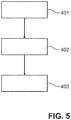
- step 401 a magnetic field is generated which provides a magnetic torque for rotating the magnetic object 4 of the measurement device 1 within the subject 40 out of its equilibrium orientation and for thereby exciting a rotational oscillation of the magnetic object 4 such that it oscillates with the resonant frequency of the rotational oscillation of the magnetic object 4.
- induction signals are generated, which are caused by the rotational oscillation of the magnetic object 4.
- the magnetic field is generated with different excitation frequencies including the resonant frequency.
- the resonant frequency is initially unknown and should be determined, it is known in which frequency range the resonant frequency will likely be present, wherein the magnetic field is generated with excitation frequencies covering the known frequency range in which the resonant frequency is to be expected.
- step 402 the temperature or the other physical or chemical quantity, respectively, is determined based on the generated induction signals and in step 403 the determined temperature or other physical or chemical quantity, respectively, is outputted.
- Steps 401 to 403 might be carried out in a loop such that substantially continuously the measurement is carried out and outputted to, for instance, a physician performing, for example, as surgical procedure, until the measurement is aborted.
- the measurement might be aborted, after a desired stop of the measurement has been indicated to the read-out system via the input unit 45.
- the measurement device can especially be used in thermal ablation procedures, in order to control the thermal energy applied to a subject depending on the measured temperature.
- the measurement device has preferentially a sub-millimeter size and can be placed in or at the tissue to be ablated, in order to monitor the temperature of the tissue during the ablation procedure.
- the measurement device provides a wireless solution for measuring the temperature or the other physical or chemical quantity like the pressure such that the measurement device may be delivered, for instance, via the blood stream to a desired location within the subject.
- the measurement device can be placed, for instance, at or within a tumor for monitoring the temperature during a tumor ablation procedure.
- the measurement device is not only very small, i.e. of sub-millimeter size, but also highly sensitive and very accurate, wherein the measurement device can be probed remotely by a coil system, for instance, as described above.
- the magnetic material to be used for modifying the temperature dependence of the measurement device as desired like the magnetic materials 5, 6 described above with reference to Fig. 1 is preferentially a low Curie temperature material, wherein this magnetic material might also be applied to the embodiments described above with reference to Figs. 2 and 3 for tailoring the temperature dependence of the resonant frequency as desired.
- the casing of the measurement device can be, for instance, a metal or polymer casing. Moreover, within the casing gas can be present or it can also contain a vacuum.
- the measurement device preferentially comprises two magnetic objects that can rotate relative to each other, wherein in an embodiment one of the two magnetic objects is fixed to the casing, for instance, by glue and the other of the magnetic objects is suspended by a filament like a fine wire or a thread.
- the oscillation frequency depends on the magnetic strength at the oscillating magnetic object, which is preferentially a sphere, and therefore on the distance between the magnetic objects.
- the measurement structure i.e. the measurement element
- the measurement element may be simply a membrane.
- a measurement element which is adapted to increase the natural temperature dependence of the resonant frequency, which is generally not very high.
- the thermal expansion of the casing might increase the distance between the magnetic objects, the thermal expansion of the filament reduces this distance.
- the overall change in resonant frequency is hence not very high depending on a temperature change.
- a filament could be used having a negative length change with increasing temperature, in order to also increase the distance between the two magnetic objects with increasing temperature.
- Such a filament could be or comprise a carbon fiber or stretched polymer fibers.
- the measurement element is an additional element like the above described magnetic material.
- the magnetic material preferentially has a Curie temperature only slightly above the maximum operation temperature of the measurement device.
- the magnetic material can be applied to many different positions within the measurement device, but preferentially the magnetic material is positioned near the further magnetic object which is preferentially fixed. Typically, the magnetic material loses magnetization with increasing temperature. However, depending on the position where this low Curie temperature material resides, the effect on the frequency is either positive or negative, i.e. the frequency is either shifted towards higher frequencies or toward lower frequencies with increasing temperature.
- the magnetic material 6 is a soft magnetic material which magnetizes in opposite direction compared to the further magnetic object 3 and thus always reduces the field strength at the position of the rotating magnetic object 4.
- the magnetic material 5 however has the same magnetization direction as the further magnetic object 3 and thus always increases the field strength and hence the resonant frequency decreases with increasing temperature.
- the magnetic material can therefore be used to compensate a wide range of unwanted temperature drifts.
- the magnetic material might be an iron nickel alloy, wherein the Curie temperature is adjustable by the composition of this alloy. However, also other low Curie materials can be used.
- the magnetic material can have, for instance, a Curie temperature being 100 K or less above the maximum operation temperature of the measurement device. In an embodiment the Curie temperature is 10 K above the maximum operation temperature of the measurement device.
- the magnetic material might also be a combination of several magnetic materials, which might be called sub magnetic material, having different Curie temperatures. If the magnetic material is a combination of several sub magnetic materials, one or several of the sub magnetic materials might also have a Curie temperature below the maximum operation temperature.
- the maximum operation temperature depends on the application for which the measurement device should be used. It might be equal to or smaller than 50 °C or equal to or smaller than 100 °C. In an embodiment the measurement device is adapted to be just used for measuring the body temperature. The maximum operation temperature might then be 50 °C. In case of ablation monitoring the maximum operation temperature might be 100 °C. If the measurement device is used in non-medical applications, the maximum operation temperature can be even higher.
- the measurement device can also comprise other measurement elements for providing a high sensitivity of the resonant frequency with respect to temperature changes.
- the vapor pressure of liquid can be used to actuate a distance change between the magnetic objects, for instance, as described above with reference to Fig. 2 .
- the thermal expansion of material is used together with a leverage construction for generating a high distance change with changing temperature, for instance, as described above with reference to Fig. 3 .
- these several measurement devices might be used simultaneously, wherein these several measurement devices are adapted to have a respective resonant frequency in a respective frequency range, when the respective measurement device is used for the measurement, and wherein the frequency ranges of different measurement devices do not overlap. This allows the read-out system to distinguish the different measurement devices based on the respective resonant frequency and to determine for each respective measurement device the respective temperature or other physical or chemical property, respectively.
- the measurement element like the above mentioned soft magnetic material is preferentially chosen and arranged such that the change of the resonant frequency depending on the temperature is larger or equal 10 Hz/K and further preferred larger or equal to 100 Hz/K. If the measurement device is adapted to measure the other physical or chemical property, the measurement element is preferentially chosen and arranged such that the dependence of the resonant frequency on the temperature is equal to or smaller than 1 Hz/K. And further preferred smaller than 0.1 Hz/K.
- measurement devices which comprise the casing, the rotatable magnetic object, the restoring torque unit providing a restoring torque to force the magnetic object back into an equilibrium orientation and a measurement element being adapted to modify the resonant frequency depending on the temperature and/or on the other physical or chemical quantity, wherein, if the measurement element is adapted to modify the resonant frequency depending on the other physical or chemical quantity, the measurement device comprises a compensation element which is adapted to modify the resonant frequency depending on the temperature in a first frequency direction depending on a temperature change which is opposite to a second frequency direction in which the measurement device would modify the resonant frequency, depending on the temperature change, if the compensation element were not part of the measurement device.
- the flexible part 8 of the casing 2 shown in Fig. 1 is rigid and the casing 2 can partly be filled with a liquid preferentially adsorbed to solid material such that vapor is present within the casing, wherein in this example the casing has some flexibility such that it, for instance, changes its length and/or can be curved, wherein this flexibility together with the temperature dependence of the vapor within the casing can lead to a change of the distance between the two magnetic objects within the casing and hence to a shift of the resonant frequency depending on the temperature.
- the leverage structure comprises more arcs than the one arc 213 shown in this figure in order to increase the temperature sensitivity.
- the restoring torque unit comprises, in addition to the further magnetic object or as an alternative, a torsion spring mechanism for providing the restoring torque.
- a torsion spring can be used instead of the filament 7 shown in Fig. 1 .
- two torsion springs are used, wherein each torsion spring connects the rotating magnetic object 4 with a respective one of the opposing and surfaces 30, 31.
- the measurement element comprises magnetic material which is applied to the magnetic object and which influences the dipole moment of the magnetic object, wherein the influence of the magnetic material depends on the temperature, in order to change the dipole moment of the magnetic object, if the temperature changes.
- magnetic material which changes its magnetization depending on the temperature, can also be applied to the rotating magnetic object.
- the measurement device is adapted to measure the pressure as the other physical or chemical quantity
- the measurement device can also be adapted to measure another physical or chemical quantity. This can be achieved, for instance, by constructing the measurement device such that a change of the desired physical or chemical quantity leads to a change of the distance between the magnetic object and the further magnetic object or, more generally, in a change of the restoring torque provided by the restoring torque unit.
- a further chemical parameter to measure would be to use a membrane made from a material (e.g. natural rubber) that changes mechanical properties in the presence of an organic solvent in the environment. If the casing has some sort of hole i.e. no pressure is measured, then this device would give the recording of organic solvents in the environment.
- a material e.g. natural rubber
- the generation of the magnetic field which provides a magnetic torque for rotating the magnetic object of the measurement device out of its equilibrium orientation and for thereby exciting a rotational oscillation of the magnetic object such that it oscillates with the resonant frequency can be implemented in many different ways.
- the excitation can use individual single pulses of a magnetic field, wherein between the pulses the frequency and phase of the induced signal can be measured. From this, the timing of the next short pulse can be computed such that it increases the oscillation amplitude of the magnetic object.
- the single pulse can be replaced with a pulse train of few pulses with positive and negative amplitudes. This short pulse train still covers a relative broad potential excitation spectrum, the center of which is designed to lay approximately at the expected resonant frequency. The timing of the pulse train is again adjusted so that it increases the oscillation amplitude of the magnetic object.
- the frequency of the resulting optimized induction signal can be regarded as being the resonant frequency.
- the read-out system can also be adapted to generate induction signals that depend on the spatial position and optionally also on the orientation of the measurement device, wherein the determination unit can be adapted to determine the position and optionally also the orientation of the measurement device based on the generated induction signals.
- the spatial sensitivity profiles of the individual coils can be used for determining the position and optionally also the orientation of the measurement device.
- a single unit or device may fulfill the functions of several items recited in the claims.
- the mere fact that certain measures are recited in mutually different dependent claims does not indicate that a combination of these measures cannot be used to advantage.
- Procedures like the determination of the temperature or of the other physical or chemical quantity, the control of the excitation of the one or several measurement devices by controlling the current within the coils, et cetera, performed by one or several units or devices can be performed by any other number of units or devices.
- These procedures and/or the control of the read-out system in accordance with the measuring method can be implemented as program code means of a computer program and/or as dedicated hardware.
- a computer program may be stored/distributed on a suitable medium, such as an optical storage medium or a solid-state medium, supplied together with or as part of other hardware, but may also be distributed in other forms, such as via the Internet or other wired or wireless telecommunication systems.
- a suitable medium such as an optical storage medium or a solid-state medium, supplied together with or as part of other hardware, but may also be distributed in other forms, such as via the Internet or other wired or wireless telecommunication systems.
- the invention relates to a measurement device comprising a rotatable magnetic object which can oscillate with a resonant frequency if excited by an external magnetic torque.
- the measurement device is adapted such that the resonant frequency depends on the temperature or on another physical or chemical quantity like pressure, in order to allow for a wireless temperature measurement or measurement of the other physical or chemical quantity via an external magnetic field providing the external magnetic torque.
- This measurement device can be relatively small, can be read-out over a relatively larger distance and allows for a very accurate measurement.
Landscapes
- Health & Medical Sciences (AREA)
- Life Sciences & Earth Sciences (AREA)
- Engineering & Computer Science (AREA)
- Surgery (AREA)
- Heart & Thoracic Surgery (AREA)
- Animal Behavior & Ethology (AREA)
- Veterinary Medicine (AREA)
- Public Health (AREA)
- General Health & Medical Sciences (AREA)
- Biomedical Technology (AREA)
- Physics & Mathematics (AREA)
- Medical Informatics (AREA)
- Molecular Biology (AREA)
- Pathology (AREA)
- Biophysics (AREA)
- Nuclear Medicine, Radiotherapy & Molecular Imaging (AREA)
- General Physics & Mathematics (AREA)
- Cardiology (AREA)
- Oral & Maxillofacial Surgery (AREA)
- Hematology (AREA)
- Physiology (AREA)
- Vascular Medicine (AREA)
- Radiology & Medical Imaging (AREA)
- Human Computer Interaction (AREA)
- Robotics (AREA)
- Pulmonology (AREA)
- Anesthesiology (AREA)
- Optics & Photonics (AREA)
- Measuring Pulse, Heart Rate, Blood Pressure Or Blood Flow (AREA)
- Magnetic Resonance Imaging Apparatus (AREA)
- Measurement Of Length, Angles, Or The Like Using Electric Or Magnetic Means (AREA)
- Media Introduction/Drainage Providing Device (AREA)
- Measuring Fluid Pressure (AREA)
- Measuring Temperature Or Quantity Of Heat (AREA)
- Electrotherapy Devices (AREA)
- Prostheses (AREA)
- Surgical Instruments (AREA)
- Radiation-Therapy Devices (AREA)
- Measuring Magnetic Variables (AREA)
- Magnetic Treatment Devices (AREA)
Priority Applications (13)
| Application Number | Priority Date | Filing Date | Title |
|---|---|---|---|
| PCT/EP2019/084447 WO2020253977A1 (en) | 2018-06-20 | 2019-12-10 | Pressure sensor for being introduced into the circulatory system of a human being |
| JP2019222748A JP7548536B2 (ja) | 2018-06-20 | 2019-12-10 | 測定装置 |
| AU2019451647A AU2019451647B2 (en) | 2018-06-20 | 2019-12-10 | Pressure sensor for being introduced into the circulatory system of a human being |
| EP19817289.2A EP3986264B1 (de) | 2018-06-20 | 2019-12-10 | Drucksensor zum einführen in das kreislaufsystem eines menschen |
| BR112021025765A BR112021025765A2 (pt) | 2018-06-20 | 2019-12-10 | Sensor de pressão para ser introduzido no sistema circulatório de um ser humano, dispositivo médico implantável, sistema de leitura do sensor de pressão, método de medição de pressão e mídia não transitória |
| US16/708,521 US11774300B2 (en) | 2018-06-20 | 2019-12-10 | Pressure sensor for being introduced into a circulatory system |
| US16/708,485 US11592341B2 (en) | 2018-06-20 | 2019-12-10 | Magnetic measurement device for measuring temperature or other property |
| CN201980099555.7A CN114269233B (zh) | 2018-06-20 | 2019-12-10 | 用于被引入到人类的循环系统中的压力传感器 |
| CN201911261739.7A CN112113584B (zh) | 2018-06-20 | 2019-12-10 | 测量装置 |
| JP2021575036A JP7507795B2 (ja) | 2018-06-20 | 2019-12-10 | 人間の循環系へ導入されるための圧力センサ、当該圧力センサを有する埋め込み式医療機器、当該圧力センサの読み取りシステム、当該読み取りシステムの作動方法、及び当該作動方法を実施させるための非一時的媒体 |
| CA3144130A CA3144130A1 (en) | 2018-06-20 | 2019-12-10 | Pressure sensor for being introduced into the circulatory system of a human being |
| US18/114,644 US20230204435A1 (en) | 2018-06-20 | 2023-02-27 | Measurement device |
| US18/237,953 US12235172B2 (en) | 2018-06-20 | 2023-08-25 | Implantable device including pressure sensor |
Applications Claiming Priority (1)
| Application Number | Priority Date | Filing Date | Title |
|---|---|---|---|
| EP18178783.9A EP3583892A1 (de) | 2018-06-20 | 2018-06-20 | Druckerfassungseinheit, system und verfahren zur ferndruckerfassung |
Publications (3)
| Publication Number | Publication Date |
|---|---|
| EP3583890A2 true EP3583890A2 (de) | 2019-12-25 |
| EP3583890A3 EP3583890A3 (de) | 2020-03-04 |
| EP3583890B1 EP3583890B1 (de) | 2023-11-22 |
Family
ID=62715915
Family Applications (7)
| Application Number | Title | Priority Date | Filing Date |
|---|---|---|---|
| EP18178783.9A Withdrawn EP3583892A1 (de) | 2018-06-20 | 2018-06-20 | Druckerfassungseinheit, system und verfahren zur ferndruckerfassung |
| EP19729752.6A Active EP3809961B1 (de) | 2018-06-20 | 2019-06-11 | Druckerfassungseinheit, system und verfahren zur ferndruckerfassung |
| EP19181528.1A Active EP3583890B1 (de) | 2018-06-20 | 2019-06-20 | Magnetische messvorrichtung |
| EP19181514.1A Active EP3583896B1 (de) | 2018-06-20 | 2019-06-20 | Verfolgungssystem und durch das verfolgungssystem zu verfolgende markierungsvorrichtung |
| EP19817289.2A Active EP3986264B1 (de) | 2018-06-20 | 2019-12-10 | Drucksensor zum einführen in das kreislaufsystem eines menschen |
| EP25199721.9A Pending EP4649990A3 (de) | 2018-06-20 | 2019-12-10 | Verfolgungssystem und durch das verfolgungssystem zu verfolgende markierungsvorrichtung |
| EP19817293.4A Pending EP3986271A1 (de) | 2018-06-20 | 2019-12-10 | Verfolgungssystem und durch das verfolgungssystem zu verfolgende markierungsvorrichtung |
Family Applications Before (2)
| Application Number | Title | Priority Date | Filing Date |
|---|---|---|---|
| EP18178783.9A Withdrawn EP3583892A1 (de) | 2018-06-20 | 2018-06-20 | Druckerfassungseinheit, system und verfahren zur ferndruckerfassung |
| EP19729752.6A Active EP3809961B1 (de) | 2018-06-20 | 2019-06-11 | Druckerfassungseinheit, system und verfahren zur ferndruckerfassung |
Family Applications After (4)
| Application Number | Title | Priority Date | Filing Date |
|---|---|---|---|
| EP19181514.1A Active EP3583896B1 (de) | 2018-06-20 | 2019-06-20 | Verfolgungssystem und durch das verfolgungssystem zu verfolgende markierungsvorrichtung |
| EP19817289.2A Active EP3986264B1 (de) | 2018-06-20 | 2019-12-10 | Drucksensor zum einführen in das kreislaufsystem eines menschen |
| EP25199721.9A Pending EP4649990A3 (de) | 2018-06-20 | 2019-12-10 | Verfolgungssystem und durch das verfolgungssystem zu verfolgende markierungsvorrichtung |
| EP19817293.4A Pending EP3986271A1 (de) | 2018-06-20 | 2019-12-10 | Verfolgungssystem und durch das verfolgungssystem zu verfolgende markierungsvorrichtung |
Country Status (9)
| Country | Link |
|---|---|
| US (10) | US12007291B2 (de) |
| EP (7) | EP3583892A1 (de) |
| JP (8) | JP7401469B2 (de) |
| CN (6) | CN112384134B (de) |
| AU (3) | AU2019290959B2 (de) |
| BR (3) | BR112020025733A2 (de) |
| CA (3) | CA3104001A1 (de) |
| ES (1) | ES2968637T3 (de) |
| WO (3) | WO2019243098A1 (de) |
Cited By (3)
| Publication number | Priority date | Publication date | Assignee | Title |
|---|---|---|---|---|
| EP4008239A1 (de) * | 2020-12-03 | 2022-06-08 | Koninklijke Philips N.V. | Mikrogerät zur ermöglichung einer lokalisierung des mikrogeräts |
| EP4145097A1 (de) | 2021-09-06 | 2023-03-08 | Koninklijke Philips N.V. | Vorrichtung zur erkennung des funktionszustands eines medizinischen implantats |
| JP2023551545A (ja) * | 2020-12-03 | 2023-12-08 | コーニンクレッカ フィリップス エヌ ヴェ | 医療器具を識別する識別システム |
Families Citing this family (39)
| Publication number | Priority date | Publication date | Assignee | Title |
|---|---|---|---|---|
| US10667931B2 (en) * | 2014-07-20 | 2020-06-02 | Restore Medical Ltd. | Pulmonary artery implant apparatus and methods of use thereof |
| EP3583892A1 (de) | 2018-06-20 | 2019-12-25 | Koninklijke Philips N.V. | Druckerfassungseinheit, system und verfahren zur ferndruckerfassung |
| US20230160980A1 (en) * | 2020-01-24 | 2023-05-25 | Jørgen Selmer Jensen | Methods and systems for obtaining flexible frequency selection and high efficiency on a low frequency magnetic field position determination |
| US20230038320A1 (en) * | 2020-02-06 | 2023-02-09 | Somatex Medical Technologies Gmbh | Implantable marker body for breast treatment |
| JP7752631B2 (ja) * | 2020-04-01 | 2025-10-10 | コーニンクレッカ フィリップス エヌ ヴェ | 誘導検知のためのコントローラ及び方法 |
| US20210338098A1 (en) * | 2020-04-30 | 2021-11-04 | Lucent Medical Systems, Inc. | Permanent magnet rotor for medical device tracking |
| EP4008249A1 (de) * | 2020-12-03 | 2022-06-08 | Koninklijke Philips N.V. | Durch ultraschall aktiviertes drahtloses mikro-magnetisches marker-schaumpatch |
| EP4014856A1 (de) | 2020-12-18 | 2022-06-22 | Koninklijke Philips N.V. | Passive drahtlose spulenbasierte marker und mit einem medizinischen auslesesystem kompatibler sensor zum verfolgen magnetomechanischer oszillatoren |
| EP4032470A1 (de) | 2021-01-25 | 2022-07-27 | Koninklijke Philips N.V. | System zum empfangen von signalen von einem magneto-mechanischen oszillator |
| US20220330799A1 (en) * | 2021-04-14 | 2022-10-20 | Arthrex, Inc | System and method for using detectable radiation in surgery |
| CN113171185A (zh) * | 2021-04-26 | 2021-07-27 | 吉林大学 | 一种磁力引导的肠道病变标记物微创探测追踪及位置锁定装置 |
| US20250235102A1 (en) * | 2021-10-22 | 2025-07-24 | Angiomed Gmbh & Co. Medizintechnik Kg | Implant |
| CN114533201B (zh) * | 2022-01-05 | 2024-06-18 | 华中科技大学同济医学院附属协和医院 | 一种体外波碎血凝块辅助设备 |
| CN114034428A (zh) * | 2022-01-10 | 2022-02-11 | 杭州未名信科科技有限公司 | 封装结构及测量导管 |
| CN114557780B (zh) * | 2022-03-01 | 2024-01-26 | 长春理工大学 | 一种辅助外科手术的三维定位系统及方法 |
| EP4498895A1 (de) | 2022-03-31 | 2025-02-05 | Koninklijke Philips N.V. | Durchflussmessendes gefässimplantat |
| US20230404432A1 (en) | 2022-05-27 | 2023-12-21 | Koninklijke Philips N.V. | Endobronchial flow meaurement and flow control for regional ventilation |
| CA3259302A1 (en) * | 2022-06-30 | 2024-01-04 | Merit Medical Systems, Inc. | IMPLANTABLE DEVICES WITH MONITORING, AND ASSOCIATED SYSTEMS AND PROCESSES |
| CN115300755A (zh) * | 2022-08-10 | 2022-11-08 | 苏州润迈德医疗科技有限公司 | 细长医疗器械运动检测装置 |
| CN119997899A (zh) | 2022-08-12 | 2025-05-13 | 德国癌症研究公共权益基金会 | 定位设备和方法 |
| JP2025529387A (ja) | 2022-09-21 | 2025-09-04 | コーニンクレッカ フィリップス エヌ ヴェ | 血管内にあるプラーク沈着物のプラークデータの提供 |
| EP4342382A1 (de) | 2022-09-21 | 2024-03-27 | Koninklijke Philips N.V. | Bereitstellung von plaquedaten für eine plaqueablagerung in einem gefäss |
| US12390199B2 (en) * | 2022-10-07 | 2025-08-19 | Koninklijke Philips N.V. | Microdevice and registration apparatus |
| EP4353175A1 (de) | 2022-10-11 | 2024-04-17 | Koninklijke Philips N.V. | Bereitstellung einer führung für ein behandlungsverfahren auf einem verstopften gefäss |
| EP4388981A1 (de) | 2022-12-22 | 2024-06-26 | Koninklijke Philips N.V. | Magnetomechanische resonatoren mit verringerter gegenseitiger anziehung |
| WO2024079073A1 (en) | 2022-10-14 | 2024-04-18 | Koninklijke Philips N.V. | Magneto-mechanical resonators with reduced mutual attraction |
| EP4623417A1 (de) | 2022-11-21 | 2025-10-01 | Koninklijke Philips N.V. | Bereitstellung von projektionsbildern |
| EP4374780A1 (de) | 2022-11-28 | 2024-05-29 | Koninklijke Philips N.V. | Vorrichtung zur verwendung bei der blutdruckmessung |
| EP4382042A1 (de) * | 2022-12-06 | 2024-06-12 | Koninklijke Philips N.V. | Erhöhung des signal-rausch-verhältnisses von magnetomechanischen miniaturresonatoren |
| EP4382066A1 (de) | 2022-12-08 | 2024-06-12 | Koninklijke Philips N.V. | Lcq-positionsmarker |
| EP4385401A1 (de) | 2022-12-13 | 2024-06-19 | Koninklijke Philips N.V. | System zur abgabe einer messvorrichtung in einen körper |
| CN116212225B (zh) * | 2023-01-06 | 2025-07-29 | 华中科技大学 | 一种人工心脏泵装置及磁性隔膜泵的制备方法 |
| CN116818149A (zh) * | 2023-06-08 | 2023-09-29 | 华中科技大学 | 一种基于3d打印的柔性自供能触觉传感器及其制造方法 |
| CN119498957A (zh) * | 2023-08-25 | 2025-02-25 | 武汉联影智融医疗科技有限公司 | 电磁导航系统及其磁场抗干扰方法、装置和电子设备 |
| WO2025080974A1 (en) | 2023-10-12 | 2025-04-17 | Alliance For Sustainable Energy, Llc | Hybrid bifurcating wave energy converters |
| US12582329B2 (en) | 2023-10-24 | 2026-03-24 | Northern Digital Inc. | Magneto-mechanical capsules |
| CN117330234B (zh) * | 2023-11-28 | 2024-03-15 | 微智医疗器械有限公司 | 一种压力传感器组件制作方法及压力传感器组件 |
| EP4625434A1 (de) | 2024-03-28 | 2025-10-01 | Koninklijke Philips N.V. | Unterstützung eines interventionellen eingriffs |
| EP4704040A1 (de) | 2024-08-26 | 2026-03-04 | Koninklijke Philips N.V. | Rendering von anatomischen regionen |
Family Cites Families (104)
| Publication number | Priority date | Publication date | Assignee | Title |
|---|---|---|---|---|
| GB626624A (en) * | 1945-03-07 | 1949-07-19 | Liquidometer Corp | Improvements in or relating to measuring devices such as barometers |
| US3564130A (en) | 1966-03-21 | 1971-02-16 | Rca Corp | Electronic photocopy system |
| GB1181515A (en) | 1966-05-18 | 1970-02-18 | Solartron Electronic Group | Improvements in or relating to Force-Measuring Apparatus. |
| US3456508A (en) * | 1967-05-24 | 1969-07-22 | Sperry Rand Corp | Vibrating diaphragm pressure sensor apparatus |
| US4044283A (en) * | 1975-10-22 | 1977-08-23 | Schiller Industries, Inc. | Electromechanical resonator |
| US4127110A (en) | 1976-05-24 | 1978-11-28 | Huntington Institute Of Applied Medical Research | Implantable pressure transducer |
| SE414672B (sv) * | 1978-11-16 | 1980-08-11 | Asea Ab | Fiberoptiskt don for metning av fysikaliska storheter sasom kraft, tojning, tryck, acceleration och temperatur |
| DE2946515A1 (de) * | 1979-11-17 | 1981-05-27 | Robert Bosch Gmbh, 7000 Stuttgart | Druckgeber mit hall-ic |
| US4254395A (en) * | 1979-12-26 | 1981-03-03 | Robert Bosch Gmbh | Electromechanical force converter for measuring gas pressure |
| US4411261A (en) * | 1980-05-15 | 1983-10-25 | Medical Engineering Corporation | Semi-rigid penile implant |
| US4523482A (en) * | 1983-09-02 | 1985-06-18 | Rockwell International Corporation | Lightweight torquemeter and torque-measuring method |
| US4720676A (en) | 1983-11-04 | 1988-01-19 | Allied Corporation | Magnetomechanical transducer utilizing resonant frequency shifts to measure pressure in response to displacement of a pressure sensitive device |
| JPS60189205A (ja) * | 1984-03-08 | 1985-09-26 | Sony Corp | 磁気装置 |
| US4922197A (en) * | 1988-08-01 | 1990-05-01 | Eaton Corporation | High resolution proximity detector employing magnetoresistive sensor disposed within a pressure resistant enclosure |
| US4938068A (en) * | 1988-09-28 | 1990-07-03 | The Slope Indicator Co. | Pressure transducer |
| US4936148A (en) * | 1988-10-17 | 1990-06-26 | Anent Systems Corporation | Hall effect pressure transducer |
| US5195377A (en) * | 1990-04-17 | 1993-03-23 | Garshelis Ivan J | Magnetoelastic force transducer for sensing force applied to a ferromagnetic member using leakage flux measurement |
| EP0524381A1 (de) * | 1991-07-22 | 1993-01-27 | Landis & Gyr Business Support AG | Mikrotechnisch hergestellte Sensorvorrichtung |
| JPH06293205A (ja) * | 1993-01-21 | 1994-10-21 | Nippondenso Co Ltd | タイヤ空気圧検出装置 |
| DE4425398A1 (de) * | 1993-07-22 | 1995-01-26 | Nippon Denso Co | Druckerfassungsgerät |
| US5627465A (en) * | 1995-10-25 | 1997-05-06 | Honeywell Inc. | Rotational position sensor with mechanical adjustment of offset and gain signals |
| US6779409B1 (en) * | 1997-01-27 | 2004-08-24 | Southwest Research Institute | Measurement of torsional dynamics of rotating shafts using magnetostrictive sensors |
| US6129668A (en) * | 1997-05-08 | 2000-10-10 | Lucent Medical Systems, Inc. | System and method to determine the location and orientation of an indwelling medical device |
| AU2001217746A1 (en) | 1998-05-14 | 2002-05-27 | Calypso Medical, Inc. | Systems and methods for locating and defining a target location within a human body |
| US6382845B1 (en) | 1999-03-02 | 2002-05-07 | Ameritech Corporation | Fiber optic patch kit and method for using same |
| US7549960B2 (en) * | 1999-03-11 | 2009-06-23 | Biosense, Inc. | Implantable and insertable passive tags |
| US7590441B2 (en) * | 1999-03-11 | 2009-09-15 | Biosense, Inc. | Invasive medical device with position sensing and display |
| JP2001242024A (ja) | 2000-02-25 | 2001-09-07 | Seiko Instruments Inc | 体内埋込式圧力感知装置並びに該感知装置を用いた圧力検出システム及び圧力調整システム |
| US6453185B1 (en) * | 2000-03-17 | 2002-09-17 | Integra Lifesciences, Inc. | Ventricular catheter with reduced size connector and method of use |
| EP1267729A2 (de) * | 2000-03-23 | 2003-01-02 | SciMed Life Systems, Inc. | Drucksensor für therapeutische abgabevorrichtung und verfahren |
| JP2001281070A (ja) * | 2000-03-28 | 2001-10-10 | Ryowa Denshi Kk | 物理量センサ |
| DE50107173D1 (de) * | 2000-06-26 | 2005-09-29 | Draegerwerk Ag | Gasfördervorrichtung für Beatmungs- und Narkosegeräte |
| US20030040670A1 (en) * | 2001-06-15 | 2003-02-27 | Assaf Govari | Method for measuring temperature and of adjusting for temperature sensitivity with a medical device having a position sensor |
| WO2003053533A2 (en) * | 2001-12-10 | 2003-07-03 | Innovision Research & Technology Plc | Detection apparatus and component detectable by the detection apparatus |
| US6838990B2 (en) | 2001-12-20 | 2005-01-04 | Calypso Medical Technologies, Inc. | System for excitation leadless miniature marker |
| US6822570B2 (en) | 2001-12-20 | 2004-11-23 | Calypso Medical Technologies, Inc. | System for spatially adjustable excitation of leadless miniature marker |
| US7699059B2 (en) | 2002-01-22 | 2010-04-20 | Cardiomems, Inc. | Implantable wireless sensor |
| US8013699B2 (en) * | 2002-04-01 | 2011-09-06 | Med-El Elektromedizinische Geraete Gmbh | MRI-safe electro-magnetic tranducer |
| US6957098B1 (en) * | 2002-06-27 | 2005-10-18 | Advanced Cardiovascular Systems, Inc. | Markers for interventional devices in magnetic resonant image (MRI) systems |
| US7769427B2 (en) | 2002-07-16 | 2010-08-03 | Magnetics, Inc. | Apparatus and method for catheter guidance control and imaging |
| US7147604B1 (en) | 2002-08-07 | 2006-12-12 | Cardiomems, Inc. | High Q factor sensor |
| US7464713B2 (en) * | 2002-11-26 | 2008-12-16 | Fabian Carl E | Miniature magnetomechanical tag for detecting surgical sponges and implements |
| US6931938B2 (en) * | 2002-12-16 | 2005-08-23 | Jeffrey G. Knirck | Measuring pressure exerted by a rigid surface |
| WO2004074013A2 (en) * | 2003-02-15 | 2004-09-02 | Advanced Digital Components, Inc. | Tire pressure monitoring system and method of using same |
| US7972616B2 (en) | 2003-04-17 | 2011-07-05 | Nanosys, Inc. | Medical device applications of nanostructured surfaces |
| US7245117B1 (en) * | 2004-11-01 | 2007-07-17 | Cardiomems, Inc. | Communicating with implanted wireless sensor |
| US8026729B2 (en) * | 2003-09-16 | 2011-09-27 | Cardiomems, Inc. | System and apparatus for in-vivo assessment of relative position of an implant |
| US6854335B1 (en) * | 2003-12-12 | 2005-02-15 | Mlho, Inc. | Magnetically coupled tire pressure sensing system |
| ATE399657T1 (de) * | 2004-02-06 | 2008-07-15 | Fiat Ricerche | Drucksensor für rotierende teile and verfahren zur druckerkennung hierfür |
| US10195464B2 (en) | 2004-06-24 | 2019-02-05 | Varian Medical Systems, Inc. | Systems and methods for treating a lung of a patient using guided radiation therapy or surgery |
| GB0417686D0 (en) * | 2004-08-09 | 2004-09-08 | Sensopad Ltd | Novel targets for inductive sensing applications |
| WO2006094156A2 (en) | 2005-03-02 | 2006-09-08 | Calypso Medical Technologies, Inc. | Systems and methods for treating a patient using guided radiation therapy or surgery |
| KR20070120997A (ko) * | 2005-04-22 | 2007-12-26 | 코닌클리케 필립스 일렉트로닉스 엔.브이. | 센서 장치를 지닌 디바이스 |
| EP1885234A2 (de) * | 2005-05-27 | 2008-02-13 | The Cleveland Clinic Foundation | Verfahren und gerät zur bestimmung einer eigenschaft eines in-vivo-sensors |
| AU2006262287A1 (en) * | 2005-06-21 | 2007-01-04 | Cardiomems, Inc. | Method of manufacturing implantable wireless sensor for in vivo pressure measurement |
| US7621036B2 (en) | 2005-06-21 | 2009-11-24 | Cardiomems, Inc. | Method of manufacturing implantable wireless sensor for in vivo pressure measurement |
| US7931577B2 (en) * | 2006-01-31 | 2011-04-26 | Tab Licensing Company, Llc | Magnetic field applicator system |
| US20070236213A1 (en) * | 2006-03-30 | 2007-10-11 | Paden Bradley E | Telemetry method and apparatus using magnetically-driven mems resonant structure |
| US7444878B1 (en) | 2006-10-30 | 2008-11-04 | Northrop Grumman Systems Corporation | Resonant frequency pressure sensor |
| JP5379695B2 (ja) * | 2006-12-20 | 2013-12-25 | コーニンクレッカ フィリップス エヌ ヴェ | 作用の領域における磁気マーカーを配置するための方法及び配列 |
| WO2008142629A2 (en) | 2007-05-24 | 2008-11-27 | Koninklijke Philips Electronics N.V. | Multifunctional marker |
| EP2214769B1 (de) * | 2007-11-23 | 2013-03-13 | Ecole Polytechnique Fédérale de Lausanne (EPFL) | Nicht-invasiv verstellbare drainagevorrichtung |
| WO2009088062A1 (ja) * | 2008-01-10 | 2009-07-16 | Akita University | 感温磁性体を用いた温度計測方法及び温度制御方法 |
| US10215825B2 (en) * | 2008-04-18 | 2019-02-26 | The United States Of America, As Represented By The Secretary, Department Of Health And Human Services | Magnetic microstructures for magnetic resonance imaging |
| US9962523B2 (en) * | 2008-06-27 | 2018-05-08 | Merit Medical Systems, Inc. | Catheter with radiopaque marker |
| RU2478338C2 (ru) | 2008-09-11 | 2013-04-10 | Эсист Медикал Системз, Инк. | Устройство и способ доставки физиологического датчика |
| WO2010056716A2 (en) * | 2008-11-11 | 2010-05-20 | Board Of Regents, The University Of Texas System | Medical devices, apparatuses, systems, and methods |
| AT507303B1 (de) * | 2008-12-11 | 2010-04-15 | Suess Dieter Dr | Sensor zum messen mechanischer spannungen |
| CA2752096C (en) * | 2009-02-26 | 2016-08-09 | The University Of British Columbia | Systems and methods for dipole enhanced inductive power transfer |
| US9870021B2 (en) * | 2009-04-15 | 2018-01-16 | SeeScan, Inc. | Magnetic manual user interface devices |
| EP2280262A1 (de) * | 2009-07-29 | 2011-02-02 | Dieter Süss | Sensorvorrichtung zum Kontaktlosen Messen von Temperaturen durch Verwendung von magnetischen Materialien nahe von Phasenübergängen |
| CN102497807B (zh) * | 2009-09-14 | 2015-06-17 | 皇家飞利浦电子股份有限公司 | 用于测量检查对象的内压的设备 |
| US9179827B2 (en) | 2009-12-15 | 2015-11-10 | Boston Scientific Scimed, Inc. | Systems and methods for determining the position and orientation of medical devices inserted into a patient |
| GB2477575B (en) * | 2010-02-09 | 2012-02-08 | Servomex Group Ltd | Apparatus and methods for imbalance compensation |
| CN103607946A (zh) * | 2011-01-20 | 2014-02-26 | 埃纳威医疗有限公司 | 估计物体的位置和取向的系统和方法 |
| EP2667770A4 (de) * | 2011-01-30 | 2016-06-22 | Guided Interventions Inc | System zur erkennung des blutdrucks mit einem druckerfassungs-führungsdraht |
| JP6222527B2 (ja) | 2011-09-01 | 2017-11-01 | マイクロテック メディカル テクノロジーズ リミテッド | 門脈及び/又は肝静脈圧の検出方法及び門脈高血圧監視システム |
| EP2811895A4 (de) * | 2012-02-07 | 2015-10-21 | Io Surgical Llc | Sensorsystem, implantierbarer sensor und verfahren zur in-vivo-fernmessung eines reizes |
| JP5475208B1 (ja) * | 2012-05-07 | 2014-04-16 | オリンパスメディカルシステムズ株式会社 | 磁界発生装置及びカプセル型医療装置誘導システム |
| JP6086984B2 (ja) * | 2012-09-17 | 2017-03-01 | ボストン サイエンティフィック サイムド,インコーポレイテッドBoston Scientific Scimed,Inc. | 圧力検知ガイドワイヤ |
| US20150289939A1 (en) * | 2012-11-07 | 2015-10-15 | Koninklijke Philips N.V. | Magnetic device for use in an mpi apparatus |
| US10335042B2 (en) * | 2013-06-28 | 2019-07-02 | Cardiovascular Systems, Inc. | Methods, devices and systems for sensing, measuring and/or characterizing vessel and/or lesion compliance and/or elastance changes during vascular procedures |
| US9601267B2 (en) * | 2013-07-03 | 2017-03-21 | Qualcomm Incorporated | Wireless power transmitter with a plurality of magnetic oscillators |
| JP6190227B2 (ja) * | 2013-09-20 | 2017-08-30 | 株式会社東芝 | 圧力センサ、マイクロフォン、血圧センサ、携帯情報端末および補聴器 |
| WO2015057518A1 (en) | 2013-10-14 | 2015-04-23 | Boston Scientific Scimed, Inc. | Pressure sensing guidewire and methods for calculating fractional flow reserve |
| US9801563B2 (en) * | 2013-11-06 | 2017-10-31 | The Charles Stark Draper Laboratory, Inc. | Micro-magnetic reporter and systems |
| WO2015085011A1 (en) * | 2013-12-04 | 2015-06-11 | Obalon Therapeutics , Inc. | Systems and methods for locating and/or characterizing intragastric devices |
| US9995715B2 (en) * | 2014-04-13 | 2018-06-12 | Rheonics Gmbh | Electromagnetic transducer for exciting and sensing vibrations of resonant structures |
| US9852832B2 (en) * | 2014-06-25 | 2017-12-26 | Allegro Microsystems, Llc | Magnetic field sensor and associated method that can sense a position of a magnet |
| EP3186627B1 (de) | 2014-08-27 | 2020-05-27 | 3M Innovative Properties Company | Magnetomechanischer resonatorsensor mit absorbierendem material |
| US20160261233A1 (en) * | 2015-03-02 | 2016-09-08 | Qualcomm Incorporated | Method and apparatus for wireless power transmission utilizing two-dimensional or three-dimensional arrays of magneto-mechanical oscillators |
| EP3135186B1 (de) | 2015-08-28 | 2020-09-30 | Heraeus Deutschland GmbH & Co. KG | Implantierbarer sensor |
| US20170084373A1 (en) * | 2015-09-21 | 2017-03-23 | Qualcomm Incorporated | Programmable magnet orientations in a magnetic array |
| KR101871030B1 (ko) * | 2015-10-26 | 2018-07-20 | 한국표준과학연구원 | 초정밀 맥동유동 발생장치, 그 맥동유동 발생장치를 갖는 인공 맥상파 재현 시스템 및 재현방법 |
| US10151606B1 (en) * | 2016-02-24 | 2018-12-11 | Ommo Technologies, Inc. | Tracking position and movement using a magnetic field |
| US10323958B2 (en) * | 2016-03-18 | 2019-06-18 | Allegro Microsystems, Llc | Assembly using a magnetic field sensor for detecting a rotation and a linear movement of an object |
| US11116419B2 (en) * | 2016-06-01 | 2021-09-14 | Becton, Dickinson And Company | Invasive medical devices including magnetic region and systems and methods |
| EP3487548B1 (de) * | 2016-07-19 | 2021-03-17 | Heartware, Inc. | Herzkammerunterstützungsvorrichtungen und integrierte sensoren dafür |
| US10296089B2 (en) * | 2016-08-10 | 2019-05-21 | Microsoft Technology Licensing, Llc | Haptic stylus |
| GB201615847D0 (en) | 2016-09-16 | 2016-11-02 | Tech Partnership The Plc | Surgical tracking |
| EP4084271A1 (de) * | 2016-09-21 | 2022-11-02 | Tc1 Llc | Systeme und verfahren zur ortung von implantierten vorrichtungen zur drahtlosen stromübertragung |
| US11241165B2 (en) * | 2017-12-05 | 2022-02-08 | St. Jude Medical International Holding S.À R.L. | Magnetic sensor for tracking the location of an object |
| EP3583892A1 (de) | 2018-06-20 | 2019-12-25 | Koninklijke Philips N.V. | Druckerfassungseinheit, system und verfahren zur ferndruckerfassung |
| CN211883773U (zh) | 2020-01-14 | 2020-11-10 | 华中科技大学同济医学院附属协和医院 | 一种压力传感器导管的固定装置 |
-
2018
- 2018-06-20 EP EP18178783.9A patent/EP3583892A1/de not_active Withdrawn
-
2019
- 2019-06-11 EP EP19729752.6A patent/EP3809961B1/de active Active
- 2019-06-11 US US17/250,141 patent/US12007291B2/en active Active
- 2019-06-11 CN CN201980040992.1A patent/CN112384134B/zh active Active
- 2019-06-11 JP JP2020570167A patent/JP7401469B2/ja active Active
- 2019-06-11 BR BR112020025733-8A patent/BR112020025733A2/pt unknown
- 2019-06-11 AU AU2019290959A patent/AU2019290959B2/en active Active
- 2019-06-11 CA CA3104001A patent/CA3104001A1/en active Pending
- 2019-06-11 WO PCT/EP2019/065090 patent/WO2019243098A1/en not_active Ceased
- 2019-06-20 EP EP19181528.1A patent/EP3583890B1/de active Active
- 2019-06-20 EP EP19181514.1A patent/EP3583896B1/de active Active
- 2019-06-20 ES ES19181528T patent/ES2968637T3/es active Active
- 2019-12-10 US US16/708,485 patent/US11592341B2/en active Active
- 2019-12-10 JP JP2019222591A patent/JP7407582B2/ja active Active
- 2019-12-10 JP JP2019222748A patent/JP7548536B2/ja active Active
- 2019-12-10 AU AU2019451647A patent/AU2019451647B2/en active Active
- 2019-12-10 CN CN202511310616.3A patent/CN120983022A/zh active Pending
- 2019-12-10 US US16/708,513 patent/US11598677B2/en active Active
- 2019-12-10 CN CN201911261739.7A patent/CN112113584B/zh active Active
- 2019-12-10 AU AU2019451287A patent/AU2019451287B2/en active Active
- 2019-12-10 CN CN201980099513.3A patent/CN114269237A/zh active Pending
- 2019-12-10 EP EP19817289.2A patent/EP3986264B1/de active Active
- 2019-12-10 CN CN201911261770.0A patent/CN112107364B/zh active Active
- 2019-12-10 WO PCT/EP2019/084502 patent/WO2020253978A1/en not_active Ceased
- 2019-12-10 US US16/708,521 patent/US11774300B2/en active Active
- 2019-12-10 WO PCT/EP2019/084447 patent/WO2020253977A1/en not_active Ceased
- 2019-12-10 JP JP2021575295A patent/JP2023505402A/ja active Pending
- 2019-12-10 CN CN201980099555.7A patent/CN114269233B/zh active Active
- 2019-12-10 CA CA3144130A patent/CA3144130A1/en active Pending
- 2019-12-10 EP EP25199721.9A patent/EP4649990A3/de active Pending
- 2019-12-10 BR BR112021026008A patent/BR112021026008A2/pt unknown
- 2019-12-10 US US16/708,493 patent/US11976985B2/en active Active
- 2019-12-10 BR BR112021025765A patent/BR112021025765A2/pt unknown
- 2019-12-10 CA CA3144550A patent/CA3144550A1/en active Pending
- 2019-12-10 JP JP2021575036A patent/JP7507795B2/ja active Active
- 2019-12-10 EP EP19817293.4A patent/EP3986271A1/de active Pending
-
2023
- 2023-02-27 US US18/114,644 patent/US20230204435A1/en active Pending
- 2023-08-25 US US18/237,953 patent/US12235172B2/en active Active
- 2023-12-07 JP JP2023206610A patent/JP7738627B2/ja active Active
-
2024
- 2024-04-04 US US18/626,378 patent/US20240264008A1/en active Pending
- 2024-05-07 US US18/657,169 patent/US20240361189A1/en active Pending
- 2024-10-18 JP JP2024184292A patent/JP7778886B2/ja active Active
-
2025
- 2025-07-15 US US19/269,434 patent/US20250341432A1/en active Pending
- 2025-11-19 JP JP2025199076A patent/JP2026032075A/ja active Pending
Cited By (6)
| Publication number | Priority date | Publication date | Assignee | Title |
|---|---|---|---|---|
| EP4008239A1 (de) * | 2020-12-03 | 2022-06-08 | Koninklijke Philips N.V. | Mikrogerät zur ermöglichung einer lokalisierung des mikrogeräts |
| WO2022117394A1 (en) * | 2020-12-03 | 2022-06-09 | Koninklijke Philips N.V. | Microdevice for allowing a localization of the microdevice |
| JP2023551545A (ja) * | 2020-12-03 | 2023-12-08 | コーニンクレッカ フィリップス エヌ ヴェ | 医療器具を識別する識別システム |
| EP4353147A3 (de) * | 2020-12-03 | 2024-06-26 | Koninklijke Philips N.V. | Mikrovorrichtung zur ermöglichung einer lokalisierung der mikrovorrichtung |
| EP4145097A1 (de) | 2021-09-06 | 2023-03-08 | Koninklijke Philips N.V. | Vorrichtung zur erkennung des funktionszustands eines medizinischen implantats |
| WO2023031258A1 (en) | 2021-09-06 | 2023-03-09 | Koninklijke Philips N.V. | Device for detecting a working status of a medical implant |
Also Published As
Similar Documents
| Publication | Publication Date | Title |
|---|---|---|
| US20230204435A1 (en) | Measurement device | |
| US20220257138A1 (en) | Tracking system and marker device to be tracked by the tracking system for a medical procedure | |
| JP2021000419A5 (de) | ||
| US11883248B2 (en) | Identifying system for identifying a medical tool like a surgical instrument | |
| RU2806663C2 (ru) | Отслеживающая система и маркерное устройство, подлежащее отслеживанию отслеживающей системой | |
| RU2806618C2 (ru) | Датчик давления для введения в систему кровообращения человека |
Legal Events
| Date | Code | Title | Description |
|---|---|---|---|
| PUAI | Public reference made under article 153(3) epc to a published international application that has entered the european phase |
Free format text: ORIGINAL CODE: 0009012 |
|
| STAA | Information on the status of an ep patent application or granted ep patent |
Free format text: STATUS: THE APPLICATION HAS BEEN PUBLISHED |
|
| AK | Designated contracting states |
Kind code of ref document: A2 Designated state(s): AL AT BE BG CH CY CZ DE DK EE ES FI FR GB GR HR HU IE IS IT LI LT LU LV MC MK MT NL NO PL PT RO RS SE SI SK SM TR |
|
| AX | Request for extension of the european patent |
Extension state: BA ME |
|
| PUAL | Search report despatched |
Free format text: ORIGINAL CODE: 0009013 |
|
| AK | Designated contracting states |
Kind code of ref document: A3 Designated state(s): AL AT BE BG CH CY CZ DE DK EE ES FI FR GB GR HR HU IE IS IT LI LT LU LV MC MK MT NL NO PL PT RO RS SE SI SK SM TR |
|
| AX | Request for extension of the european patent |
Extension state: BA ME |
|
| RIC1 | Information provided on ipc code assigned before grant |
Ipc: A61B 17/00 20060101ALN20200128BHEP Ipc: A61B 5/0205 20060101AFI20200128BHEP Ipc: A61M 25/09 20060101ALN20200128BHEP Ipc: A61M 25/01 20060101ALI20200128BHEP Ipc: A61B 90/00 20160101ALI20200128BHEP Ipc: G01L 19/14 20060101ALI20200128BHEP Ipc: A61B 90/30 20160101ALN20200128BHEP Ipc: A61B 34/20 20160101ALN20200128BHEP Ipc: A61B 5/06 20060101ALN20200128BHEP Ipc: A61B 5/0215 20060101ALN20200128BHEP Ipc: A61B 5/00 20060101ALN20200128BHEP |
|
| RAP1 | Party data changed (applicant data changed or rights of an application transferred) |
Owner name: KONINKLIJKE PHILIPS N.V. |
|
| STAA | Information on the status of an ep patent application or granted ep patent |
Free format text: STATUS: REQUEST FOR EXAMINATION WAS MADE |
|
| 17P | Request for examination filed |
Effective date: 20200904 |
|
| RBV | Designated contracting states (corrected) |
Designated state(s): AL AT BE BG CH CY CZ DE DK EE ES FI FR GB GR HR HU IE IS IT LI LT LU LV MC MK MT NL NO PL PT RO RS SE SI SK SM TR |
|
| REG | Reference to a national code |
Ref country code: DE Free format text: PREVIOUS MAIN CLASS: A61B0005020500 Ref country code: DE Ref legal event code: R079 Ref document number: 602019041783 Country of ref document: DE Free format text: PREVIOUS MAIN CLASS: A61B0005020500 Ipc: A61B0005010000 |
|
| GRAP | Despatch of communication of intention to grant a patent |
Free format text: ORIGINAL CODE: EPIDOSNIGR1 |
|
| STAA | Information on the status of an ep patent application or granted ep patent |
Free format text: STATUS: GRANT OF PATENT IS INTENDED |
|
| RIC1 | Information provided on ipc code assigned before grant |
Ipc: G01K 7/36 20060101ALN20230606BHEP Ipc: A61M 25/09 20060101ALN20230606BHEP Ipc: A61B 90/30 20160101ALN20230606BHEP Ipc: A61B 34/20 20160101ALN20230606BHEP Ipc: A61B 17/00 20060101ALN20230606BHEP Ipc: A61B 5/03 20060101ALN20230606BHEP Ipc: A61B 5/0215 20060101ALN20230606BHEP Ipc: A61B 5/0205 20060101ALN20230606BHEP Ipc: A61B 5/00 20060101ALN20230606BHEP Ipc: G01L 19/14 20060101ALI20230606BHEP Ipc: A61M 25/01 20060101ALI20230606BHEP Ipc: A61B 90/00 20160101ALI20230606BHEP Ipc: A61B 5/06 20060101ALI20230606BHEP Ipc: A61B 5/01 20060101AFI20230606BHEP |
|
| INTG | Intention to grant announced |
Effective date: 20230629 |
|
| GRAS | Grant fee paid |
Free format text: ORIGINAL CODE: EPIDOSNIGR3 |
|
| GRAA | (expected) grant |
Free format text: ORIGINAL CODE: 0009210 |
|
| STAA | Information on the status of an ep patent application or granted ep patent |
Free format text: STATUS: THE PATENT HAS BEEN GRANTED |
|
| AK | Designated contracting states |
Kind code of ref document: B1 Designated state(s): AL AT BE BG CH CY CZ DE DK EE ES FI FR GB GR HR HU IE IS IT LI LT LU LV MC MK MT NL NO PL PT RO RS SE SI SK SM TR |
|
| REG | Reference to a national code |
Ref country code: GB Ref legal event code: FG4D |
|
| REG | Reference to a national code |
Ref country code: CH Ref legal event code: EP Ref country code: DE Ref legal event code: R096 Ref document number: 602019041783 Country of ref document: DE |
|
| REG | Reference to a national code |
Ref country code: IE Ref legal event code: FG4D |
|
| REG | Reference to a national code |
Ref country code: NL Ref legal event code: FP |
|
| REG | Reference to a national code |
Ref country code: LT Ref legal event code: MG9D |
|
| PG25 | Lapsed in a contracting state [announced via postgrant information from national office to epo] |
Ref country code: GR Free format text: LAPSE BECAUSE OF FAILURE TO SUBMIT A TRANSLATION OF THE DESCRIPTION OR TO PAY THE FEE WITHIN THE PRESCRIBED TIME-LIMIT Effective date: 20240223 |
|
| PG25 | Lapsed in a contracting state [announced via postgrant information from national office to epo] |
Ref country code: IS Free format text: LAPSE BECAUSE OF FAILURE TO SUBMIT A TRANSLATION OF THE DESCRIPTION OR TO PAY THE FEE WITHIN THE PRESCRIBED TIME-LIMIT Effective date: 20240322 |
|
| PG25 | Lapsed in a contracting state [announced via postgrant information from national office to epo] |
Ref country code: LT Free format text: LAPSE BECAUSE OF FAILURE TO SUBMIT A TRANSLATION OF THE DESCRIPTION OR TO PAY THE FEE WITHIN THE PRESCRIBED TIME-LIMIT Effective date: 20231122 |
|
| REG | Reference to a national code |
Ref country code: AT Ref legal event code: MK05 Ref document number: 1633087 Country of ref document: AT Kind code of ref document: T Effective date: 20231122 |
|
| PG25 | Lapsed in a contracting state [announced via postgrant information from national office to epo] |
Ref country code: AT Free format text: LAPSE BECAUSE OF FAILURE TO SUBMIT A TRANSLATION OF THE DESCRIPTION OR TO PAY THE FEE WITHIN THE PRESCRIBED TIME-LIMIT Effective date: 20231122 |
|
| PG25 | Lapsed in a contracting state [announced via postgrant information from national office to epo] |
Ref country code: LT Free format text: LAPSE BECAUSE OF FAILURE TO SUBMIT A TRANSLATION OF THE DESCRIPTION OR TO PAY THE FEE WITHIN THE PRESCRIBED TIME-LIMIT Effective date: 20231122 Ref country code: IS Free format text: LAPSE BECAUSE OF FAILURE TO SUBMIT A TRANSLATION OF THE DESCRIPTION OR TO PAY THE FEE WITHIN THE PRESCRIBED TIME-LIMIT Effective date: 20240322 Ref country code: GR Free format text: LAPSE BECAUSE OF FAILURE TO SUBMIT A TRANSLATION OF THE DESCRIPTION OR TO PAY THE FEE WITHIN THE PRESCRIBED TIME-LIMIT Effective date: 20240223 Ref country code: BG Free format text: LAPSE BECAUSE OF FAILURE TO SUBMIT A TRANSLATION OF THE DESCRIPTION OR TO PAY THE FEE WITHIN THE PRESCRIBED TIME-LIMIT Effective date: 20240222 Ref country code: AT Free format text: LAPSE BECAUSE OF FAILURE TO SUBMIT A TRANSLATION OF THE DESCRIPTION OR TO PAY THE FEE WITHIN THE PRESCRIBED TIME-LIMIT Effective date: 20231122 Ref country code: PT Free format text: LAPSE BECAUSE OF FAILURE TO SUBMIT A TRANSLATION OF THE DESCRIPTION OR TO PAY THE FEE WITHIN THE PRESCRIBED TIME-LIMIT Effective date: 20240322 |
|
| REG | Reference to a national code |
Ref country code: ES Ref legal event code: FG2A Ref document number: 2968637 Country of ref document: ES Kind code of ref document: T3 Effective date: 20240513 |
|
| PG25 | Lapsed in a contracting state [announced via postgrant information from national office to epo] |
Ref country code: SE Free format text: LAPSE BECAUSE OF FAILURE TO SUBMIT A TRANSLATION OF THE DESCRIPTION OR TO PAY THE FEE WITHIN THE PRESCRIBED TIME-LIMIT Effective date: 20231122 Ref country code: RS Free format text: LAPSE BECAUSE OF FAILURE TO SUBMIT A TRANSLATION OF THE DESCRIPTION OR TO PAY THE FEE WITHIN THE PRESCRIBED TIME-LIMIT Effective date: 20231122 Ref country code: PL Free format text: LAPSE BECAUSE OF FAILURE TO SUBMIT A TRANSLATION OF THE DESCRIPTION OR TO PAY THE FEE WITHIN THE PRESCRIBED TIME-LIMIT Effective date: 20231122 Ref country code: NO Free format text: LAPSE BECAUSE OF FAILURE TO SUBMIT A TRANSLATION OF THE DESCRIPTION OR TO PAY THE FEE WITHIN THE PRESCRIBED TIME-LIMIT Effective date: 20240222 Ref country code: LV Free format text: LAPSE BECAUSE OF FAILURE TO SUBMIT A TRANSLATION OF THE DESCRIPTION OR TO PAY THE FEE WITHIN THE PRESCRIBED TIME-LIMIT Effective date: 20231122 Ref country code: HR Free format text: LAPSE BECAUSE OF FAILURE TO SUBMIT A TRANSLATION OF THE DESCRIPTION OR TO PAY THE FEE WITHIN THE PRESCRIBED TIME-LIMIT Effective date: 20231122 |
|
| PG25 | Lapsed in a contracting state [announced via postgrant information from national office to epo] |
Ref country code: DK Free format text: LAPSE BECAUSE OF FAILURE TO SUBMIT A TRANSLATION OF THE DESCRIPTION OR TO PAY THE FEE WITHIN THE PRESCRIBED TIME-LIMIT Effective date: 20231122 |
|
| PG25 | Lapsed in a contracting state [announced via postgrant information from national office to epo] |
Ref country code: CZ Free format text: LAPSE BECAUSE OF FAILURE TO SUBMIT A TRANSLATION OF THE DESCRIPTION OR TO PAY THE FEE WITHIN THE PRESCRIBED TIME-LIMIT Effective date: 20231122 |
|
| PG25 | Lapsed in a contracting state [announced via postgrant information from national office to epo] |
Ref country code: SK Free format text: LAPSE BECAUSE OF FAILURE TO SUBMIT A TRANSLATION OF THE DESCRIPTION OR TO PAY THE FEE WITHIN THE PRESCRIBED TIME-LIMIT Effective date: 20231122 |
|
| PG25 | Lapsed in a contracting state [announced via postgrant information from national office to epo] |
Ref country code: SM Free format text: LAPSE BECAUSE OF FAILURE TO SUBMIT A TRANSLATION OF THE DESCRIPTION OR TO PAY THE FEE WITHIN THE PRESCRIBED TIME-LIMIT Effective date: 20231122 Ref country code: SK Free format text: LAPSE BECAUSE OF FAILURE TO SUBMIT A TRANSLATION OF THE DESCRIPTION OR TO PAY THE FEE WITHIN THE PRESCRIBED TIME-LIMIT Effective date: 20231122 Ref country code: RO Free format text: LAPSE BECAUSE OF FAILURE TO SUBMIT A TRANSLATION OF THE DESCRIPTION OR TO PAY THE FEE WITHIN THE PRESCRIBED TIME-LIMIT Effective date: 20231122 Ref country code: EE Free format text: LAPSE BECAUSE OF FAILURE TO SUBMIT A TRANSLATION OF THE DESCRIPTION OR TO PAY THE FEE WITHIN THE PRESCRIBED TIME-LIMIT Effective date: 20231122 Ref country code: DK Free format text: LAPSE BECAUSE OF FAILURE TO SUBMIT A TRANSLATION OF THE DESCRIPTION OR TO PAY THE FEE WITHIN THE PRESCRIBED TIME-LIMIT Effective date: 20231122 Ref country code: CZ Free format text: LAPSE BECAUSE OF FAILURE TO SUBMIT A TRANSLATION OF THE DESCRIPTION OR TO PAY THE FEE WITHIN THE PRESCRIBED TIME-LIMIT Effective date: 20231122 |
|
| REG | Reference to a national code |
Ref country code: DE Ref legal event code: R097 Ref document number: 602019041783 Country of ref document: DE |
|
| PLBE | No opposition filed within time limit |
Free format text: ORIGINAL CODE: 0009261 |
|
| STAA | Information on the status of an ep patent application or granted ep patent |
Free format text: STATUS: NO OPPOSITION FILED WITHIN TIME LIMIT |
|
| PG25 | Lapsed in a contracting state [announced via postgrant information from national office to epo] |
Ref country code: SI Free format text: LAPSE BECAUSE OF FAILURE TO SUBMIT A TRANSLATION OF THE DESCRIPTION OR TO PAY THE FEE WITHIN THE PRESCRIBED TIME-LIMIT Effective date: 20231122 |
|
| 26N | No opposition filed |
Effective date: 20240823 |
|
| PG25 | Lapsed in a contracting state [announced via postgrant information from national office to epo] |
Ref country code: SI Free format text: LAPSE BECAUSE OF FAILURE TO SUBMIT A TRANSLATION OF THE DESCRIPTION OR TO PAY THE FEE WITHIN THE PRESCRIBED TIME-LIMIT Effective date: 20231122 |
|
| PG25 | Lapsed in a contracting state [announced via postgrant information from national office to epo] |
Ref country code: MC Free format text: LAPSE BECAUSE OF FAILURE TO SUBMIT A TRANSLATION OF THE DESCRIPTION OR TO PAY THE FEE WITHIN THE PRESCRIBED TIME-LIMIT Effective date: 20231122 |
|
| REG | Reference to a national code |
Ref country code: CH Ref legal event code: PL |
|
| PG25 | Lapsed in a contracting state [announced via postgrant information from national office to epo] |
Ref country code: LU Free format text: LAPSE BECAUSE OF NON-PAYMENT OF DUE FEES Effective date: 20240620 |
|
| PG25 | Lapsed in a contracting state [announced via postgrant information from national office to epo] |
Ref country code: IE Free format text: LAPSE BECAUSE OF NON-PAYMENT OF DUE FEES Effective date: 20240620 |
|
| PG25 | Lapsed in a contracting state [announced via postgrant information from national office to epo] |
Ref country code: CH Free format text: LAPSE BECAUSE OF NON-PAYMENT OF DUE FEES Effective date: 20240630 Ref country code: BE Free format text: LAPSE BECAUSE OF NON-PAYMENT OF DUE FEES Effective date: 20240630 |
|
| REG | Reference to a national code |
Ref country code: BE Ref legal event code: MM Effective date: 20240630 |
|
| PGFP | Annual fee paid to national office [announced via postgrant information from national office to epo] |
Ref country code: DE Payment date: 20250626 Year of fee payment: 7 |
|
| PGFP | Annual fee paid to national office [announced via postgrant information from national office to epo] |
Ref country code: GB Payment date: 20250617 Year of fee payment: 7 |
|
| PGFP | Annual fee paid to national office [announced via postgrant information from national office to epo] |
Ref country code: NL Payment date: 20250624 Year of fee payment: 7 |
|
| PGFP | Annual fee paid to national office [announced via postgrant information from national office to epo] |
Ref country code: FR Payment date: 20250624 Year of fee payment: 7 |
|
| PG25 | Lapsed in a contracting state [announced via postgrant information from national office to epo] |
Ref country code: FI Free format text: LAPSE BECAUSE OF FAILURE TO SUBMIT A TRANSLATION OF THE DESCRIPTION OR TO PAY THE FEE WITHIN THE PRESCRIBED TIME-LIMIT Effective date: 20231122 |
|
| PGFP | Annual fee paid to national office [announced via postgrant information from national office to epo] |
Ref country code: ES Payment date: 20250710 Year of fee payment: 7 |
|
| PGFP | Annual fee paid to national office [announced via postgrant information from national office to epo] |
Ref country code: IT Payment date: 20250623 Year of fee payment: 7 |
|
| PG25 | Lapsed in a contracting state [announced via postgrant information from national office to epo] |
Ref country code: CY Free format text: LAPSE BECAUSE OF FAILURE TO SUBMIT A TRANSLATION OF THE DESCRIPTION OR TO PAY THE FEE WITHIN THE PRESCRIBED TIME-LIMIT; INVALID AB INITIO Effective date: 20190620 |
|
| PG25 | Lapsed in a contracting state [announced via postgrant information from national office to epo] |
Ref country code: HU Free format text: LAPSE BECAUSE OF FAILURE TO SUBMIT A TRANSLATION OF THE DESCRIPTION OR TO PAY THE FEE WITHIN THE PRESCRIBED TIME-LIMIT; INVALID AB INITIO Effective date: 20190620 |