EP3583645B1 - Procédé de fabrication d'une plaque bipolaire pour piles à combustible à membrane à échange de protons (pemfc) - Google Patents
Procédé de fabrication d'une plaque bipolaire pour piles à combustible à membrane à échange de protons (pemfc) Download PDFInfo
- Publication number
- EP3583645B1 EP3583645B1 EP18714696.4A EP18714696A EP3583645B1 EP 3583645 B1 EP3583645 B1 EP 3583645B1 EP 18714696 A EP18714696 A EP 18714696A EP 3583645 B1 EP3583645 B1 EP 3583645B1
- Authority
- EP
- European Patent Office
- Prior art keywords
- substrate
- layer
- carbon
- ions
- nitrogen
- Prior art date
- Legal status (The legal status is an assumption and is not a legal conclusion. Google has not performed a legal analysis and makes no representation as to the accuracy of the status listed.)
- Active
Links
- 239000000446 fuel Substances 0.000 title claims description 28
- 239000012528 membrane Substances 0.000 title claims description 17
- 238000004519 manufacturing process Methods 0.000 title claims description 10
- 229910052799 carbon Inorganic materials 0.000 claims description 84
- 239000000758 substrate Substances 0.000 claims description 83
- OKTJSMMVPCPJKN-UHFFFAOYSA-N Carbon Chemical compound [C] OKTJSMMVPCPJKN-UHFFFAOYSA-N 0.000 claims description 75
- 238000000034 method Methods 0.000 claims description 61
- 230000008569 process Effects 0.000 claims description 45
- IJGRMHOSHXDMSA-UHFFFAOYSA-N Atomic nitrogen Chemical compound N#N IJGRMHOSHXDMSA-UHFFFAOYSA-N 0.000 claims description 42
- VYZAMTAEIAYCRO-UHFFFAOYSA-N Chromium Chemical compound [Cr] VYZAMTAEIAYCRO-UHFFFAOYSA-N 0.000 claims description 32
- 229910052804 chromium Inorganic materials 0.000 claims description 31
- 239000011651 chromium Substances 0.000 claims description 31
- 229910052757 nitrogen Inorganic materials 0.000 claims description 26
- 238000005121 nitriding Methods 0.000 claims description 20
- -1 carbon ions Chemical class 0.000 claims description 18
- 239000000463 material Substances 0.000 claims description 17
- 150000002500 ions Chemical class 0.000 claims description 13
- 239000012298 atmosphere Substances 0.000 claims description 10
- 239000001257 hydrogen Substances 0.000 claims description 9
- 229910052739 hydrogen Inorganic materials 0.000 claims description 9
- UFHFLCQGNIYNRP-UHFFFAOYSA-N Hydrogen Chemical compound [H][H] UFHFLCQGNIYNRP-UHFFFAOYSA-N 0.000 claims description 8
- 238000005530 etching Methods 0.000 claims description 8
- 238000002513 implantation Methods 0.000 claims description 8
- 239000010935 stainless steel Substances 0.000 claims description 8
- 229910001220 stainless steel Inorganic materials 0.000 claims description 8
- 238000010891 electric arc Methods 0.000 claims description 7
- RTAQQCXQSZGOHL-UHFFFAOYSA-N Titanium Chemical compound [Ti] RTAQQCXQSZGOHL-UHFFFAOYSA-N 0.000 claims description 6
- 230000015572 biosynthetic process Effects 0.000 claims description 6
- 239000010936 titanium Substances 0.000 claims description 6
- 229910052719 titanium Inorganic materials 0.000 claims description 6
- 238000005255 carburizing Methods 0.000 claims description 5
- 238000004049 embossing Methods 0.000 claims description 5
- 238000011282 treatment Methods 0.000 claims description 5
- XKRFYHLGVUSROY-UHFFFAOYSA-N Argon Chemical compound [Ar] XKRFYHLGVUSROY-UHFFFAOYSA-N 0.000 claims description 4
- 239000002318 adhesion promoter Substances 0.000 claims description 4
- 238000005256 carbonitriding Methods 0.000 claims description 4
- 230000009467 reduction Effects 0.000 claims description 4
- 125000004432 carbon atom Chemical group C* 0.000 claims description 3
- 229910052786 argon Inorganic materials 0.000 claims description 2
- QJGQUHMNIGDVPM-UHFFFAOYSA-N nitrogen group Chemical group [N] QJGQUHMNIGDVPM-UHFFFAOYSA-N 0.000 claims 2
- 239000010410 layer Substances 0.000 description 138
- 229910052751 metal Inorganic materials 0.000 description 20
- 239000002184 metal Substances 0.000 description 20
- 239000000835 fiber Substances 0.000 description 13
- 238000002161 passivation Methods 0.000 description 12
- 238000000576 coating method Methods 0.000 description 11
- 230000007797 corrosion Effects 0.000 description 11
- 238000005260 corrosion Methods 0.000 description 11
- 229910000831 Steel Inorganic materials 0.000 description 9
- WGLPBDUCMAPZCE-UHFFFAOYSA-N Trioxochromium Chemical class O=[Cr](=O)=O WGLPBDUCMAPZCE-UHFFFAOYSA-N 0.000 description 9
- 229910000423 chromium oxide Inorganic materials 0.000 description 9
- 239000011248 coating agent Substances 0.000 description 9
- 239000010959 steel Substances 0.000 description 9
- QVGXLLKOCUKJST-UHFFFAOYSA-N atomic oxygen Chemical compound [O] QVGXLLKOCUKJST-UHFFFAOYSA-N 0.000 description 8
- 239000007789 gas Substances 0.000 description 8
- 230000004048 modification Effects 0.000 description 8
- 238000012986 modification Methods 0.000 description 8
- 239000001301 oxygen Substances 0.000 description 8
- 229910052760 oxygen Inorganic materials 0.000 description 8
- 238000009792 diffusion process Methods 0.000 description 6
- 229910021645 metal ion Inorganic materials 0.000 description 6
- 239000002344 surface layer Substances 0.000 description 6
- 239000004753 textile Substances 0.000 description 6
- PXHVJJICTQNCMI-UHFFFAOYSA-N Nickel Chemical compound [Ni] PXHVJJICTQNCMI-UHFFFAOYSA-N 0.000 description 5
- 230000001133 acceleration Effects 0.000 description 5
- 239000000853 adhesive Substances 0.000 description 4
- 230000001070 adhesive effect Effects 0.000 description 4
- 125000004429 atom Chemical group 0.000 description 4
- CXOWYMLTGOFURZ-UHFFFAOYSA-N azanylidynechromium Chemical compound [Cr]#N CXOWYMLTGOFURZ-UHFFFAOYSA-N 0.000 description 4
- 238000004140 cleaning Methods 0.000 description 4
- 238000000151 deposition Methods 0.000 description 4
- 230000000694 effects Effects 0.000 description 4
- 238000004544 sputter deposition Methods 0.000 description 4
- 239000000126 substance Substances 0.000 description 4
- XLYOFNOQVPJJNP-UHFFFAOYSA-N water Substances O XLYOFNOQVPJJNP-UHFFFAOYSA-N 0.000 description 4
- 238000004833 X-ray photoelectron spectroscopy Methods 0.000 description 3
- 239000002253 acid Substances 0.000 description 3
- 238000000137 annealing Methods 0.000 description 3
- 230000008021 deposition Effects 0.000 description 3
- 238000003487 electrochemical reaction Methods 0.000 description 3
- 230000003116 impacting effect Effects 0.000 description 3
- XEEYBQQBJWHFJM-UHFFFAOYSA-N iron Substances [Fe] XEEYBQQBJWHFJM-UHFFFAOYSA-N 0.000 description 3
- JEIPFZHSYJVQDO-UHFFFAOYSA-N iron(III) oxide Inorganic materials O=[Fe]O[Fe]=O JEIPFZHSYJVQDO-UHFFFAOYSA-N 0.000 description 3
- 239000000203 mixture Substances 0.000 description 3
- 229910052759 nickel Inorganic materials 0.000 description 3
- 238000012545 processing Methods 0.000 description 3
- 238000012546 transfer Methods 0.000 description 3
- 230000007704 transition Effects 0.000 description 3
- 239000012790 adhesive layer Substances 0.000 description 2
- 229910045601 alloy Inorganic materials 0.000 description 2
- 239000000956 alloy Substances 0.000 description 2
- 238000004458 analytical method Methods 0.000 description 2
- 230000008901 benefit Effects 0.000 description 2
- 238000006243 chemical reaction Methods 0.000 description 2
- 239000007795 chemical reaction product Substances 0.000 description 2
- 230000007423 decrease Effects 0.000 description 2
- 230000007547 defect Effects 0.000 description 2
- PCHJSUWPFVWCPO-UHFFFAOYSA-N gold Chemical compound [Au] PCHJSUWPFVWCPO-UHFFFAOYSA-N 0.000 description 2
- 239000010931 gold Substances 0.000 description 2
- 229910052737 gold Inorganic materials 0.000 description 2
- 230000006872 improvement Effects 0.000 description 2
- 230000002452 interceptive effect Effects 0.000 description 2
- 229910052742 iron Inorganic materials 0.000 description 2
- 150000002739 metals Chemical class 0.000 description 2
- 239000007800 oxidant agent Substances 0.000 description 2
- 239000002245 particle Substances 0.000 description 2
- 238000005240 physical vapour deposition Methods 0.000 description 2
- 231100000572 poisoning Toxicity 0.000 description 2
- 230000000607 poisoning effect Effects 0.000 description 2
- 239000007858 starting material Substances 0.000 description 2
- 230000003746 surface roughness Effects 0.000 description 2
- 238000004381 surface treatment Methods 0.000 description 2
- 229920000049 Carbon (fiber) Polymers 0.000 description 1
- 238000013459 approach Methods 0.000 description 1
- 239000010953 base metal Substances 0.000 description 1
- 239000011324 bead Substances 0.000 description 1
- 150000001721 carbon Chemical class 0.000 description 1
- 239000004917 carbon fiber Substances 0.000 description 1
- 230000008859 change Effects 0.000 description 1
- 238000001311 chemical methods and process Methods 0.000 description 1
- 229910001430 chromium ion Inorganic materials 0.000 description 1
- 239000000498 cooling water Substances 0.000 description 1
- 238000005520 cutting process Methods 0.000 description 1
- 238000011161 development Methods 0.000 description 1
- 230000018109 developmental process Effects 0.000 description 1
- 238000001704 evaporation Methods 0.000 description 1
- 238000007730 finishing process Methods 0.000 description 1
- 229910002804 graphite Inorganic materials 0.000 description 1
- 239000010439 graphite Substances 0.000 description 1
- 150000002431 hydrogen Chemical class 0.000 description 1
- 230000001771 impaired effect Effects 0.000 description 1
- 239000007943 implant Substances 0.000 description 1
- 239000012535 impurity Substances 0.000 description 1
- 230000003993 interaction Effects 0.000 description 1
- 230000007774 longterm Effects 0.000 description 1
- 238000001465 metallisation Methods 0.000 description 1
- 150000004767 nitrides Chemical class 0.000 description 1
- 239000012299 nitrogen atmosphere Substances 0.000 description 1
- 229910052756 noble gas Inorganic materials 0.000 description 1
- 150000002835 noble gases Chemical class 0.000 description 1
- 238000005457 optimization Methods 0.000 description 1
- 239000011368 organic material Substances 0.000 description 1
- 230000035515 penetration Effects 0.000 description 1
- 238000001020 plasma etching Methods 0.000 description 1
- 239000002574 poison Substances 0.000 description 1
- 231100000614 poison Toxicity 0.000 description 1
- 239000005518 polymer electrolyte Substances 0.000 description 1
- 239000011148 porous material Substances 0.000 description 1
- 230000001681 protective effect Effects 0.000 description 1
- 230000035945 sensitivity Effects 0.000 description 1
- 239000007784 solid electrolyte Substances 0.000 description 1
- 238000005092 sublimation method Methods 0.000 description 1
- 238000006557 surface reaction Methods 0.000 description 1
- 238000012360 testing method Methods 0.000 description 1
- 238000011144 upstream manufacturing Methods 0.000 description 1
- 238000007740 vapor deposition Methods 0.000 description 1
- 238000003466 welding Methods 0.000 description 1
Images


Classifications
-
- H—ELECTRICITY
- H01—ELECTRIC ELEMENTS
- H01M—PROCESSES OR MEANS, e.g. BATTERIES, FOR THE DIRECT CONVERSION OF CHEMICAL ENERGY INTO ELECTRICAL ENERGY
- H01M8/00—Fuel cells; Manufacture thereof
- H01M8/02—Details
- H01M8/0202—Collectors; Separators, e.g. bipolar separators; Interconnectors
- H01M8/0204—Non-porous and characterised by the material
- H01M8/0223—Composites
- H01M8/0228—Composites in the form of layered or coated products
-
- H—ELECTRICITY
- H01—ELECTRIC ELEMENTS
- H01M—PROCESSES OR MEANS, e.g. BATTERIES, FOR THE DIRECT CONVERSION OF CHEMICAL ENERGY INTO ELECTRICAL ENERGY
- H01M8/00—Fuel cells; Manufacture thereof
- H01M8/02—Details
- H01M8/0202—Collectors; Separators, e.g. bipolar separators; Interconnectors
- H01M8/0204—Non-porous and characterised by the material
- H01M8/0206—Metals or alloys
-
- H—ELECTRICITY
- H01—ELECTRIC ELEMENTS
- H01M—PROCESSES OR MEANS, e.g. BATTERIES, FOR THE DIRECT CONVERSION OF CHEMICAL ENERGY INTO ELECTRICAL ENERGY
- H01M8/00—Fuel cells; Manufacture thereof
- H01M8/10—Fuel cells with solid electrolytes
- H01M2008/1095—Fuel cells with polymeric electrolytes
-
- H—ELECTRICITY
- H01—ELECTRIC ELEMENTS
- H01M—PROCESSES OR MEANS, e.g. BATTERIES, FOR THE DIRECT CONVERSION OF CHEMICAL ENERGY INTO ELECTRICAL ENERGY
- H01M8/00—Fuel cells; Manufacture thereof
- H01M8/02—Details
- H01M8/0202—Collectors; Separators, e.g. bipolar separators; Interconnectors
- H01M8/0204—Non-porous and characterised by the material
- H01M8/0206—Metals or alloys
- H01M8/0208—Alloys
- H01M8/021—Alloys based on iron
-
- H—ELECTRICITY
- H01—ELECTRIC ELEMENTS
- H01M—PROCESSES OR MEANS, e.g. BATTERIES, FOR THE DIRECT CONVERSION OF CHEMICAL ENERGY INTO ELECTRICAL ENERGY
- H01M8/00—Fuel cells; Manufacture thereof
- H01M8/02—Details
- H01M8/0202—Collectors; Separators, e.g. bipolar separators; Interconnectors
- H01M8/0247—Collectors; Separators, e.g. bipolar separators; Interconnectors characterised by the form
-
- Y—GENERAL TAGGING OF NEW TECHNOLOGICAL DEVELOPMENTS; GENERAL TAGGING OF CROSS-SECTIONAL TECHNOLOGIES SPANNING OVER SEVERAL SECTIONS OF THE IPC; TECHNICAL SUBJECTS COVERED BY FORMER USPC CROSS-REFERENCE ART COLLECTIONS [XRACs] AND DIGESTS
- Y02—TECHNOLOGIES OR APPLICATIONS FOR MITIGATION OR ADAPTATION AGAINST CLIMATE CHANGE
- Y02E—REDUCTION OF GREENHOUSE GAS [GHG] EMISSIONS, RELATED TO ENERGY GENERATION, TRANSMISSION OR DISTRIBUTION
- Y02E60/00—Enabling technologies; Technologies with a potential or indirect contribution to GHG emissions mitigation
- Y02E60/30—Hydrogen technology
- Y02E60/50—Fuel cells
-
- Y—GENERAL TAGGING OF NEW TECHNOLOGICAL DEVELOPMENTS; GENERAL TAGGING OF CROSS-SECTIONAL TECHNOLOGIES SPANNING OVER SEVERAL SECTIONS OF THE IPC; TECHNICAL SUBJECTS COVERED BY FORMER USPC CROSS-REFERENCE ART COLLECTIONS [XRACs] AND DIGESTS
- Y02—TECHNOLOGIES OR APPLICATIONS FOR MITIGATION OR ADAPTATION AGAINST CLIMATE CHANGE
- Y02P—CLIMATE CHANGE MITIGATION TECHNOLOGIES IN THE PRODUCTION OR PROCESSING OF GOODS
- Y02P70/00—Climate change mitigation technologies in the production process for final industrial or consumer products
- Y02P70/50—Manufacturing or production processes characterised by the final manufactured product
Definitions
- the invention relates to a bipolar plate for electrochemical cells, in particular for polymer electrolyte fuel cells or proton exchange membrane (PEM) fuel cells, and a manufacturing method.
- Fuel cells are used to generate electrical energy from a fuel and an oxidizing agent through an electrochemical reaction.
- Proton Exchange Membrane (PEM) fuel cells (PEMFC) are particularly suitable for mobile applications, such as in vehicles.
- PEM Proton Exchange Membrane
- electrochemical cells in such a way that an electrochemical reaction is initiated with electrical energy, in which hydrogen can be obtained as a reaction product.
- the term fuel cell is to be used in general, with other electrochemical cells naturally also being understood by this term.
- Bipolar plates are used in the fuel cell to supply hydrogen, oxygen and to drain water and cooling water as well as to pick up electrons released from the electrodes of the respective fuel cell in order to provide an electrical voltage.
- a fuel cell supplies a useful electrical voltage of 0.5 V - 2.0 V between the two electrodes. It is important that the electrons released as a result of the electrochemical reaction are absorbed as efficiently as possible on the hydrogen side (anode side) and on the oxygen side (cathode side). can be fed back into the process as efficiently as possible. This means that the lowest possible electrical contact or passage resistance occurs. An electrical resistance at this point has a direct influence on the efficiency of the BiP and thus the fuel cell.
- a gas-permeable element is arranged, which can also be referred to as a gas diffusion layer (GDL) and which is, for example, a textile, open-pore structure, which is preferably made of or with electrically conductive fibers, in particular carbon fibers is formed.
- GDL gas diffusion layer
- a gas-permeable element fulfills the tasks of distributing gas emerging from channels of a BiP as homogeneously as possible on the surface of the membrane and forwarding the electrons given off by the hydrogen as fuel to the BiP and the electrons supplied by the BiP to the water being formed to forward the oxidizing agent side.
- the electrical contact resistance of the BiP should be as low as possible
- the GDL must be pressed against the BiP with high surface pressure in order to create as many contact points and thus electrical current paths as possible to build.
- any process water must be drained off or the membrane unit must be moistened.
- the electrical contact resistance (and thus the loss) decreases with increasing surface pressure.
- the surface pressure cannot be increased at will, since then the membrane and the BiP, which is advantageously formed from a metal sheet as thin as possible, preferably a stainless steel sheet, are mechanically damaged.
- the contact resistance of the BiP can be reduced by surface modification of the metal used for the production of a BiP (e.g. rust and acid-resistant steels). With sufficient corrosion protection through surface modification, it is also conceivable to use metals with less rust and corrosion protection.
- the electrical contact resistance is usually relatively high due to the natural, poorly conductive passive layer on the surface of the metal, in particular, for example, in the case of rust- and acid-resistant steel in the form of a chromium oxide layer. A mechanical, chemical and / or physical removal of a passive layer before start-up does not bring any satisfactory improvement and it regenerates very quickly.
- the GDL is compressed and pressed more strongly against the surface of the BiP.
- the need not to compress the GDL too much in order to ensure sufficient gas diffusion and the mechanical stability of the BiP there are limits to the increase in the contact pressure.
- the mechanical stability of the BiP plate can, however, as described below, be increased through a suitable surface finish.
- this object is achieved with a production method which has the features of claim 1.
- Advantageous refinements and developments can be implemented with features identified in the subordinate claims.
- the bipolar plate according to the invention for electrochemical cells in particular for proton exchange membrane (PEM) fuel cells, is formed with a metallic substrate.
- the substrate On the surface, the substrate is provided with a carbon-based layer that reduces the electrical contact resistance, a layer system or a boundary layer, which is formed from a mainly sp2-bonded carbon-based layer near the surface with a carbon content in the range 50% to 100%, which is on a layer compared to the starting material modified metallic surface of the substrate is applied, provided.
- Individual elevations and / or depressions should be dimensioned and geometrically designed on the surface of the substrate so that fibers with which the gas-permeable element is formed as a textile structure are in touching contact over their outer circumference with at least 10% of their outer surface area, in one Area of the surface of the substrate in which a depression is present and in which a fiber and the surface of the substrate touch, are in touching contact; wherein depressions are preferably formed in the surface of the substrate with the same orientation and at constant intervals between depressions arranged next to one another.
- a metallic substrate On the surface that is in touching contact with a gas-permeable element within the electrochemical cell, a metallic substrate can have a structure which is formed with elevations and / or depressions in the respective surface.
- An increase in the roughness and the specific surface of the surface of the substrate which is in touching contact with a gas-permeable element within a fuel cell can advantageously be achieved by means of an etching process.
- a layer system or a boundary layer or the formation of an edge layer it is advantageous to at least partially remove an oxide layer present on the surface of the substrate.
- the removal can preferably be carried out by means of an etching process in argon, nitrogen or a reduction of the oxide in a particularly preferably hydrogen-containing atmosphere.
- Complete removal of an oxide layer can be advantageous here.
- partial removal can be advantageous, particularly in the case of chromium oxide layers.
- a partial conversion of the chromium oxide can be used, e.g. in the case of rust and acid-resistant steels, to utilize the enrichment of the metal forming the passivation layer, e.g. chromium there for protection against corrosion in the event of damage to the carbon and nitrogen-rich zone above.
- an adhesion promoter layer preferably as a thin layer of chromium, titanium or a layer formed with chromium and titanium, can be applied to the substrate surface before the graphitic carbon-based layer, a layer system or a boundary layer is applied, preferably by means of an electric arc discharge process in a vacuum be formed.
- the graphitic carbon-based layer, a layer system or a boundary layer can, with ionized and accelerated carbon ions, which carbon atoms present on the surface of the substrate, strike at temperatures in the range 80 ° C to 600 ° C, preferably in the range 200 ° C to 500 ° C, in particular be formed with a layer thickness of ⁇ 80 nm. At least almost 100% ionization of the carbon can be achieved by means of a pulse arc evaporator. It is advantageous here that highly ionized and accelerated carbon ions strike carbon atoms on the surface at the elevated temperatures.
- the layer should be applied to a carbon sublated layer. In order to minimize the escape of metal ions and thus prevent poisoning of the membrane unit, no metallic components should be installed. The bias voltage should be lower than with a sublantation.
- the electrons of an evaporator for carbon preferably an arc evaporator
- the electrons of an evaporator for carbon can be used in a vacuum to ionize nitrogen with auxiliary electrodes.
- the nitrogen ions can then be accelerated towards the sheet metal surface with a bias voltage.
- the highly ionized carbon of the evaporator can also be introduced into the metal surface with the same bias voltage.
- the diffusion process of nitrogen into the depth of the substrate material can be accelerated by impacting carbon ions or the diffusion process of carbon by impacting nitrogen ions. With such a process, the removal of the chromium oxide layer can also be dispensed with.
- the plasma nitrocarburizing to form the edge layer can be carried out in an atmosphere containing nitrogen close to vacuum, at a pressure in the range 10 -1 mbar to 10 -3 mbar by a nitriding treatment in which nitrogen ions are accelerated towards the substrate surface.
- An electrically negative bias voltage in the range 500 V to 1000 V is preferably applied to the substrate or the substrate is connected to ground potential.
- a temperature in the range of 350 ° C - 500 ° C should be maintained.
- Plasma nitrocarborized layers can be designed as hard outer layers in such a way that a higher contact pressure is exerted on the bipolar plate can be and thus improved electrical contact resistances can be achieved. Instead of higher contact pressures, thinner metal sheets can also be used as substrates with the same contact pressures. Plasma nitrocarburized surfaces can also be used as corrosion-resistant surfaces with good adhesion for carbon layers.
- Edge layer systems or structures can be produced in a strip finishing process without serious losses in performance in the fuel cell and then the appropriately treated strip-shaped substrate material can be formed into bipolar plates.
- edge layers can be stretched and thinned in the zone of the highest degree of deformation.
- Depressions in the structured substrate surface can be formed irregularly. However, they are preferably designed with the same orientation and at constant intervals between depressions arranged next to one another. These depressions or surface structures can advantageously be so pronounced that in areas of the BiP that are not in direct contact with the GDL there is a preferred flow direction of reaction products of the fuel cell process from the active area. In this exemplary embodiment, the surface structure would have anisotropic properties and be designed accordingly. Furthermore, advantageous properties of such a structuring can consist in the fact that improved electrical contacting becomes possible if the contact between GDL and BiP is not regular and therefore there is no electrically conductive contact or a reduced contact pressure between GDL and BiP.
- a layer or edge zone which is preferably made of amorphous graphitic or graphite, can be used to further increase the electrical conductivity or reduce the electrical contact resistance is formed nano- or microstructured carbon, be applied.
- an edge layer can be formed on the surface of the BiP, which is formed with nitride and / or carbon, by nitriding and / or carburizing, in particular by plasma nitrocarburizing.
- a graphitic carbon layer should preferably be formed completely closed with several atomic layers or structures arranged one above the other or preferably next to one another, in particular perpendicular to the BiP surface. It can be formed in a vacuum by means of a plasma, which is preferably generated with an electric arc discharge. The plasma is preferably designed as a pulsed plasma with almost 100% degrees of ionization.
- a high energy input and thus the temperature of the process or external heat sources should ensure that the carbon layers develop graphitically (sp2 bond). These are, for example, surface temperatures in the range 50 ° C-500 ° C, preferably around 300 ° C.
- High ionizations and applied acceleration voltages (bias) between the evaporator and the metal surface of the substrate mean that the ions with high energies, preferably> 100 eV, strike carbon on the surface.
- the ratio of temperature, vacuum pressure (possibly with process gas) and acceleration voltage of the carbon ions is important, whereby it should be noted that if the pressure is too high, the formation of electrically conductive layers is advantageously suppressed can be.
- suitable carbon layers can also be produced at room temperature within the limit value.
- the acceleration voltage should typically be lower than in the case of preceding carbon sublimation processes to increase the adhesive strength.
- high acceleration voltages eg 1000 V
- Such layers can, as in the case of a plasma nitrocarburized layer, also be used as a carbon electrode (layer or edge layer thickness 1 nm - 20 nm).
- Another graphitic carbon top layer should be made as thin as possible, e.g. ⁇ 80 nm. In order to minimize the escape of metal ions and thus prevent poisoning of the membrane unit, no metallic components should be installed.
- An intermediate layer in particular a chrome layer, with which the adhesion of the carbon layer and the corrosion resistance of the BiP can be improved, can be present between the structured surface of a substrate and a layer or an edge layer.
- an intermediate chromium layer can ensure that a stable chromium passivation layer is formed. In this way, the corrosion but also the escape of iron ions, which can poison the membrane unit of an electrochemical cell, can be prevented and the suitability for forming can be improved. If the membrane unit is excessively contaminated by chromium ions, the chromium layer can be replaced with a titanium layer, for example.
- an intermediate layer can also be selected which is formed with both chromium and titanium.
- the surfaces can be cleaned beforehand, e.g. by metal ion sputtering.
- An advantageous variant of the production of a BiP consists in executing the coatings and surface structuring on strip-shaped material and then reshaping this strip-shaped material in subsequent processes, cutting it into shape and welding it.
- a strip process it is advantageous to use the strip from a classic strip annealing process with a reducing atmosphere (e.g. suitable hydrogen content) out under protective gas conditions.
- a reducing atmosphere e.g. suitable hydrogen content
- a complete or partial reduction of the oxide layer, for example chromium oxide can be ensured here without additional processing steps and the strip heat can be used in the further course of the process.
- Such a process can be carried out in a vacuum chamber by etching in a hydrogen-containing gas.
- the chromium enrichment which typically occurs in the passivating intermediate layer of stainless steel, after a reducing treatment instead of a chromium adhesion promoter layer.
- the procedure can be that the structuring of the surface of a BiP which is in contact with a gas-permeable element and which is in touching contact with a gas-permeable element (GDL) in a fuel cell, with elevations and / or depressions on the latter Surface is formed by material removal and / or by an embossing process.
- the structuring can, however, also be brought about by the interaction of the surface treatments with high degrees of deformation of the sheet metal to form the flow field geometry.
- the material can be removed with at least one laser beam, preferably by interference of several laser beams in an irradiated area of the respective surface of the BiP.
- a locally defined material removal can advantageously be achieved in a very short time.
- a wide variety of patterns can be obtained in a defined form on the surface by structuring, so that a relatively high degree of flexibility is given.
- the roughness and specific surface of the respective surface of a substrate for a BiP can be increased in a vacuum by bombardment with ions, which preferably have an energy in the range from 10 2 eV to 75 * 10 3 eV.
- An edge layer can also be formed on the respective surface of the substrate of a BiP by means of a nitriding, carburizing or nitrocarburizing process by means of a plasma while maintaining a suitable temperature and atmosphere.
- An edge layer can preferably be obtained by means of nitrocarburizing in such a way that nitriding is carried out first and then followed a carburization of the surface layer is carried out. It is advantageous here that this also creates additional hard edge layers which hinder the deformation of the bipolar plate in the deformed state and thus enable the use of thinner sheets or higher contact pressures.
- An improvement in the electrical current transfer from the GDL to the BiP without increasing the contact pressure can be achieved by combining a microstructuring of the surface of the BiPs with a chemical change (coating, nitriding). This increases the size of the areas that are in touching contact with one another, and thereby the intrinsic electrical surface resistance can be reduced.
- the characteristics of the structuring can be stochastic, i.e. randomly, for example, through an etching process or deterministically through a laser structuring or an embossing process.
- the combination of material removal by means of laser structuring or an embossing process and the subsequent etching of the substrate surface is particularly advantageous here.
- the approach described has the advantage that lower electrical contact resistances can be achieved than surfaces coated with gold. This enables significant cost savings and increases in efficiency with BiP. Further cost savings in the production of the surface structures and the edge layers lie in the execution of the process steps in a strip process, in particular roll-to-roll processing and the subsequent processing of the refined strip material into BiP or fuel cells. Such firmly adhesive layers can be produced on strip material and then reshaped without the performance in the fuel cell being significantly impaired.
- edge layers can be stretched and thinned in the zone of the highest degree of deformation. In these areas, a characteristic crack structure of the coating or edge layer caused by deformation can also occur.
- Surface structuring and / or surface layers or surface layer systems can be used due to their electrical properties and the corrosion protection effect in order to be able to use cheaper metals in fuel cells. These include, for example, metal strips made of 1.4301 or ferritic steels.
- the combination of the surface structuring process with a surface coating offers the advantage of enabling further reduced electrical contact and transition resistances as well as increased corrosion resistance through the surface functionalization.
- a BiP can be produced as follows:
- the structuring can e.g. B. by means of an ns-pulsed Nd: YAG laser beam.
- This laser beam is directed onto the surface, for example with a pulse length of 10 ns, a wavelength of 1064 nm and a pulse energy of 1 J.
- the laser beam can also be modified using laser optics between the laser source and the surface of the BiP. For example, by splitting the original laser beam, two laser beams can be obtained, which are superimposed (interfering) again on the surface of the substrate. The superimposition and focusing can take place in such a way that pulse energy densities (laser fluences) of approx. 2 J / cm 2 are achieved in the irradiated area.
- the angle between the interfering partial laser beams can be chosen so that the resulting interference period on the surface corresponds to 20 ⁇ m. This enables linear structures with a period of 20 ⁇ m to be created. In this case, the structure depths are approx. 1 ⁇ m - 10 ⁇ m.
- the respective surface can be removed by bombarding ions of sufficient energy (10 2 eV to several 10 3 eV). It is based on a momentum transfer of an impacting ion with the substrate surface.
- the impulse is introduced into the substrate material by elastic "core impacts” and initiates a cascade of impacts. This allows surface atoms to receive an outward momentum.
- Is the kinetic energy of the incident ions above the binding energy of the atoms of the substrate material these can mainly be atomized as individual atoms, but also in the form of atom clusters, from the substrate surface.
- the structure depths are approx. 0.05 ⁇ m - 2 ⁇ m.
- a high electrical voltage bias voltage
- a low-pressure plasma is generated with the aid of noble gases.
- the generated high-energy particles can be accelerated in the direction of the substrate surface by the applied electrical current potential and material can be removed from the surface.
- a plasma fine cleaning of the surface of a substrate for a BiP can be implemented and the surface roughness of the surface influenced in this way can be increased.
- a structured surface of a substrate can additionally be provided with a coating formed from at least one layer.
- metal surfaces are galvanized or chrome-plated in order to protect them against corrosion in the long term.
- high redox potentials occur in the fuel cell, which have a very aggressive effect and can cause damage or chemical processes. If metal-based BiP is used, it can corrode.
- the aim of a metallic BiP is to increase the corrosion resistance and to ensure good electrical conductivity.
- a suitable method here can be the arc-supported glow discharge.
- electrons are generated by means of an arc evaporator and accelerated towards an additional cooled anode, while the resulting ions can be shielded.
- nitrogen is ionized above the surface to be treated at pressures in the range of 10 -1 mbar - 10 -3 mbar and either at earth potential (mass) or with a negative bias voltage of approx. 200 V - 5000 V. lying substrate accelerated.
- the N ions impinging on the passivation layer preferably a chromium oxide layer in the case of austenitic steels, can be implanted / subplanted or diffuse close to the surface.
- the surface is cleaned at the same time.
- an edge layer with high carbon and nitrogen contents can be formed.
- the carbon implantation is preferably carried out with arc evaporators and high acceleration voltages> 500 V.
- the electrons of a carbon evaporator preferably an arc evaporator
- the electrons of a carbon evaporator can be used in a vacuum to ionize nitrogen and introduce it into the substrate surface in parallel.
- the nitrogen ions can then be accelerated towards the substrate surface with a bias voltage.
- the highly ionized carbon can also be introduced into the metal surface of the substrate with the evaporator with the same bias voltage.
- the chromium content can decrease towards the surface, contrary to other processes in which additional chromium is applied or at nitriding temperatures with gas nitriding with temperatures> 800 ° C ( Fig. 4th ).
- the modification of the edge layer can be limited to the part of the passivation layer near the surface, for example to 10 nm-20 nm. However, modification depths in the range of 5 ⁇ m can also be achieved.
- the carbon implantation or sublantation process can be used to drive the nitrogen into greater depths or to modify the passivation layer.
- the energy supply of the carbon process also helps to ensure a suitable temperature control for the nitrogen diffusion processes taking place.
- Carbon layers with good adhesive strength can also be deposited on such surfaces. However, even without such carbon layers, contact resistances that are as good or better as gold layers can be achieved before and after the stack test.
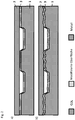
- Figure 1 Several examples are shown of surface that are in touching contact with a gas-permeable element within a fuel cell.
- Figure 1a a conventional planar surface of a substrate 1 of a bipolar plate and a fiber 2 of a gas-permeable element formed as a textile with fibers 2 without structuring according to the prior art is shown.
- Figure 1b shows a flat planar surface of a substrate 1 of a bipolar plate, which is coated with a layer 3 and a fiber 2 of a gas-permeable element rests on the surface.
- FIG. 1c An irregularly structured and with a layer 3 coated or modified surface of a substrate 1 of a bipolar plate, in which a fiber 2 of the gas-permeable element is arranged in a recess of the structure and the fiber 2 is in contact with 20% of its circumference in the region of the recess Contact with the structured surface of the substrate 1 of the bipolar plate is in Figure 1c shown.
- FIGS. 1d and 1e Examples of a regularly structured surface of a substrate 1 of a bipolar plate are to be illustrated.
- several depressions are formed in the surface of the substrate 1 of the bipolar plate in a form not shown.
- the depressions are each dimensioned the same, aligned in the same direction and formed at the same intervals from one another.
- At least part of a fiber surface of a gas-permeable element designed as a textile structure is inserted into each recess, so that there the surface of fibers 2 with at least 20% of their outer circumferential surface on the surface of the bipolar plate 1 (see Fig. Fig. 1e ) or the surface of a layer 3 or surface modification which has been formed on the surface of the substrate 1 of the bipolar plate is in touching contact.
- Layers 3 as they are in the Figures 1b to 1d can be used as follows for the Figures 3a to 3g still to be described, as a layer system 3, several layers formed one above the other or in the surface diffused or implanted elements or a combination thereof.
- FIG. 2a shows schematically the surface 3 of a substrate 1 of a bipolar plate with a smooth structure which, due to a manufacturing or assembly inaccuracy, does not have contact everywhere with the GDL 2, which is formed, for example, with fibers 2.1, the membrane unit of an electrochemical cell. This deteriorates the electrical current transfer.
- the GDL 2 with the fibers 2.1 can adapt better to a structured surface and thus has better contact with the modified surface 3.
- Figure 3a a bipolar plate with a substrate 1 made of a stainless steel 1.4404, on the surface of which is in touching contact with the gas-permeable element 2 when an electrochemical cell has been mounted, a layer system is arranged. After cleaning the surface of impurities and oxides z. B. by means of metal ion sputtering, chromium is deposited by means of a PVD process, for example by means of an arc evaporator.
- chromium layer 7 at temperatures between 200 ° C - 500 ° C, carbon is evaporated as an adhesion-promoting component by means of a pulsed or DC arc evaporator and ionized with high negative bias voltages (eg 1000 V) is implanted or subplanted. As a result, a carbon-rich surface layer or a carbon layer 5 obtained by subplantation is formed. Using a pulsed arc evaporator, highly ionized carbon is then deposited at lower bias voltages (eg ⁇ 500 V). Based on the high degree of ionization and the high energies of the impinging ions as well as the resulting surface tension and the temperature, a highly conductive nano- or micro-structured carbon layer 4 is formed on the surface.
- high negative bias voltages eg 1000 V
- the layer system or the surface modifications in the Figures 3a to 3g On a substrate surface of a bipolar plate, depressions and / or elevations can be formed on a structured surface, but this is not shown in these illustrations.
- the layers 4, 5, 6, 7, 8 and 9 are each shown on a flat strip surface of a substrate 1 before a forming process. But you can also click on already formed Substrates 1 for bipolar plates can be realized.
- the chromium passivation layer 8 is not completely removed but only partially converted near the surface, so that the oxygen content is reduced. This can be done by annealing in a hydrogen atmosphere, but also by etching processes.
- the carbon layer 5 is then implanted or subplanted into the chromium-rich former chromium oxide passivation layer 8, as described above, without a chromium intermediate layer 7.
- a very carbon-rich surface is formed on the surface of the former oxide layer, in which parts of the metal with which the substrate 1 is formed can still be found, the relative chromium and nickel content being increased and oxygen being additionally present.
- the chromium oxide passivation layer 8 is completely or at least 80% removed before the coating, e.g. by means of an etching process, and a carbon layer 5 obtained by subplantation with a thickness of ⁇ 20 nm is then applied as described above.
- the carbon layer 4 described in example 3a is deposited thereon (layer thickness 10-80 nm).
- the described chromium passivation layer 8 is applied to a surface that has been cleaned or partially converted as explained in example 3b, so that the oxygen content is reduced.
- a carbon layer 4 is then applied without first implanting or sublating carbon.
- Example 3e is a typical plasma nitrocarburized surface.
- prior plasma etching was dispensed with here.
- the edge layer 6 is partially converted by the simultaneous sub- or implantation of carbon and nitrogen ions. This also results in a certain cleaning effect, e.g. for existing water skins or organic material. Close to the surface, high carbon concentrations are achieved with moderate nitrogen introduction. The nitrogen ionization can thereby through a glow discharge in a nitrogen atmosphere excited by electrons from an arc evaporator.
- Carbon evaporators but also chromium evaporators or other arc-evaporating substances can be used for this purpose.
- the nitrogen ions and the carbon ions are accelerated to the surface by high bias voltages (eg 1000V).
- the processes can be carried out simultaneously or one after the other.
- the ions, in particular the carbon ions can be used to ionize the nitrogen and also to advantageously support diffusion into the metal surface. If possible, only thin edge layers 6 in the range ⁇ 100 nm should be treated. As few metal ions as possible should remain on the surface. In all nitriding operations or carbon implantation processes, the excessive formation of CrN or CrC should be avoided by using a suitable temperature regime.
- a pure nitriding process takes place without carbon, as described in example 3e. This is carried out longer so that greater depths of penetration can result.
- This edge layer 9 formed by nitriding then enables the firmly adhering deposition of a carbon layer 4, as described in example 3a.
- a previous removal or conversion of a passivation layer 8, if necessary, can again be dispensed with.
- Such layers can then also be implemented at depths of up to 5 ⁇ m. In all nitriding operations, the excessive formation of CrN should be avoided by using a suitable temperature regime.
- Fig. 3g is the shift system according to Figure 3f supplemented by an intermediate layer 7 made of chromium, for example 40 nm. This is deposited as described in FIG. 3a.
- Intermediate layers 7 made of chromium can be used in particular in the case of steels with a lower chromium content in order to ensure adequate corrosion resistance in the event of damage to the cover layer (cracks, scratches, etc.).
- Chromium intermediate layers 7 of this type can also be used in the case of laser weld seams in order to include a weld seam upper bead To alloy chrome.
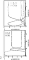
- Figure 4a shows the schematic XPS element analysis of a GLC layer system as it is in Fig. 3a is shown schematically in cross section.
- the entire layer system should preferably be implemented in a thickness range of 100 nm with a thin adhesive layer 7 made of chromium. All processes can be carried out in a pressure range of 10 -1 - 10 -3 mbar.
- the carbon content is almost 100%.
- This carbon layer 5 also results in a mixed layer of chromium and carbon or, in areas remote from the surface, layers which can be formed from Cr, C, Fe and other alloy components of the starting material.
- a typical XPS element analysis of a PNC surface treatment shows Figure 4b . Characteristically, the carbon content of the carbon layer 5 obtained by subplantation is lower than that of a pure carbon layer 4.
Landscapes
- Chemical & Material Sciences (AREA)
- Sustainable Energy (AREA)
- Life Sciences & Earth Sciences (AREA)
- Engineering & Computer Science (AREA)
- Manufacturing & Machinery (AREA)
- Sustainable Development (AREA)
- Chemical Kinetics & Catalysis (AREA)
- Electrochemistry (AREA)
- General Chemical & Material Sciences (AREA)
- Composite Materials (AREA)
- Fuel Cell (AREA)
- Solid-Phase Diffusion Into Metallic Material Surfaces (AREA)
- Physical Vapour Deposition (AREA)
Claims (12)
- Procédé de fabrication d'une plaque bipolaire pour des cellules de combustible à membrane échangeuse de protons (PEM), qui est constituée d'un substrat métallique (1) en acier inoxydable, et chez lequelune couche superficielle (6) est formée sur une surface du substrat (1) par un procédé de nitration, un procédé de carburation ou un procédé de carbonitruration en maintenant une atmosphère adéquate au moyen d'un plasma, et/oula surface du substrat (1) respective est revêtue d'une couche graphitique (3, 4, 5) sous vide au moyen d'un plasmaetune structuration de la surface du substrat (1) recouverte et/ou formée avec une couche superficielle, en contact avec un élément (2) perméable aux gaz, qui est en contact matériel dans une cellule électrochimique avec l'élément (2) perméable aux gaz, est conçue avec des protubérances et/ou des creux sur cette surface au moyen d'un retrait de matière et/ou d'un procédé d'estampage.
- Procédé selon la revendication précédente, caractérisé en ce que, lors d'une carbonitruration, on effectue d'abord une nitruration et ensuite une carburation de la couche superficielle (6).
- Procédé selon la revendication 1, caractérisé en ce que la surface respective du substrat (1) est revêtue avec une couche graphitique (3, 4, 5), qui est totalement fermée avec plusieurs couches d'atomes disposées les unes sur les autres, sous vide au moyen d'un plasma, qui est de préférence généré avec une décharge par arc électrique.
- Procédé selon la revendication précédente, caractérisé en ce qu'avant l'application d'une couche graphitique (3, 4, 5) ou la formation d'une couche superficielle (6), une couche d'oxyde présente sur la surface du substrat (1) est retirée au moins partiellement ou est réduite ; où
le retrait est effectué au moyen d'un procédé de gravure dans de l'argon, de l'azote ou d'une réduction de l'oxyde dans une atmosphère contenant de l'hydrogène. - Procédé selon l'une des deux revendications précédentes, caractérisé en ce qu'une couche de promoteur d'adhésion (7) à base de chrome, de titane, ou une couche qui est constituée avec du chrome et du titane, est formée sur la surface du substrat avant l'application de la couche graphitique (3, 4, 5) au moyen d'un procédé de décharge par arc électrique sous vide.
- Procédé selon l'une des cinq revendications précédentes, caractérisé en ce que la couche graphitique (3, 4, 5) est formée avec des atomes de carbone ionisés et accélérés, qui est formée sur les atomes de carbone présents sur la surface du substrat (1) à des températures dans la plage de 80 °C à 600 °C avec une épaisseur de couche < 80 nm.
- Procédé selon la revendication précédente, caractérisé en ce qu'une ionisation à au moins presque 100 % du carbone est atteinte au moyen d'un évaporateur à arc par impulsions.
- Procédé selon la revendication 1 ou la revendication 2, caractérisé en ce que la carbonitruration par plasma pour la formation de la couche superficielle (6) dans une atmosphère contenant de l'azote proche du vide à une pression dans la plage de 10-1 mbar à 10-3 mbar par un traitement de nitration, dans lequel les ions d'azote sont accélérées en direction de la surface du substrat, où une tension électrique de bias dans la plage de 500 V à 1000 V est appliquée au substrat (1), ou le substrat (1) est relié au potentiel de la terre et est maintenu à une température dans la plage de 300 °C à 500 °C.
- Procédé selon la revendication précédente, caractérisé en ce que des ions d'azote sont créés au moyen d'une décharge luminescente assistée d'une décharge par arc électrique et sont accélérés en direction d'une anode refroidie, tandis que des ions d'azote créés sont isolés et accélérés en direction de la surface du substrat.
- Procédé selon l'une des revendications précédentes, caractérisé en ce que le retrait de matière pour la formation des protubérances et/ou des creux peut être réalisé avec au moins un rayonnement laser dans une zone irradiée de la surface de substrat respective, et/ou la rugosité et la surface spécifique de la surface respective d'un substrat (1) sont augmentées par un bombardement d'ions.
- Procédé selon la revendication précédente, caractérisé en ce que des protubérances et/ou des creux peuvent être réalisés avec au moins un rayonnement laser, de préférence, par l'interférence de plusieurs rayonnements laser, dans une zone irradiée de la surface du substrat respective, et/ou la rugosité et la surface spécifique de la surface respective d'un substrats (1) sont augmentées par un bombardement d'ions qui présentent une énergie dans la plage de 102 eV à 104 eV dans des conditions de vide.
- Procédé selon la revendication 1 ou la revendication 2, caractérisé en ce que la carbonitruration par plasma pour la formation d'une couche superficielle (6) a lieu dans une atmosphère contenant de l'azote proche du vide à une pression dans la plage de 10-1 mbar à 10-3 mbar par un traitement de nitration, dans lequel des ions d'azote sont créés par les électrons d'un évaporateur de carbone et sont accélérés en direction de la surface du substrat par une différence de potentiel appliquée et la sublantation, respectivement l'implantation, de carbone a lieu parallèlement par le même évaporateur de carbone.
Applications Claiming Priority (2)
| Application Number | Priority Date | Filing Date | Title |
|---|---|---|---|
| DE102017202679.0A DE102017202679A1 (de) | 2017-02-20 | 2017-02-20 | Bipolarplatte für elektrochemische Zellen sowie ein Herstellungsverfahren |
| PCT/EP2018/054122 WO2018150046A1 (fr) | 2017-02-20 | 2018-02-20 | Plaque bipolaire pour cellules de combustible et procédé de fabrication |
Publications (2)
| Publication Number | Publication Date |
|---|---|
| EP3583645A1 EP3583645A1 (fr) | 2019-12-25 |
| EP3583645B1 true EP3583645B1 (fr) | 2021-01-13 |
Family
ID=61837716
Family Applications (1)
| Application Number | Title | Priority Date | Filing Date |
|---|---|---|---|
| EP18714696.4A Active EP3583645B1 (fr) | 2017-02-20 | 2018-02-20 | Procédé de fabrication d'une plaque bipolaire pour piles à combustible à membrane à échange de protons (pemfc) |
Country Status (7)
| Country | Link |
|---|---|
| US (1) | US11114675B2 (fr) |
| EP (1) | EP3583645B1 (fr) |
| JP (1) | JP7035068B2 (fr) |
| KR (1) | KR20190121754A (fr) |
| CN (1) | CN110313090A (fr) |
| DE (1) | DE102017202679A1 (fr) |
| WO (1) | WO2018150046A1 (fr) |
Cited By (1)
| Publication number | Priority date | Publication date | Assignee | Title |
|---|---|---|---|---|
| EP4191715A1 (fr) | 2021-12-01 | 2023-06-07 | Federal-Mogul Burscheid GmbH | Plaque bipolaire pour piles à combustible |
Families Citing this family (8)
| Publication number | Priority date | Publication date | Assignee | Title |
|---|---|---|---|---|
| DE102018219056A1 (de) | 2018-11-08 | 2020-05-14 | Technische Universität Dresden | Verfahren zur Herstellung von Bipolarplatten für Brennstoffzellen |
| JP7448522B2 (ja) | 2019-03-22 | 2024-03-12 | 日鉄ケミカル&マテリアル株式会社 | 複合材及びその製造方法、並びに当該複合材を用いた燃料電池用のセパレータ、セル及びスタック |
| EP3778982B1 (fr) * | 2019-08-14 | 2023-07-05 | IHI Hauzer Techno Coating B.V. | Procédé de revêtement d'un ou de plusieurs composants métalliques d'un empilement de piles à combustible, composant d'un empilement de piles à combustible et appareil de revêtement d'un ou de plusieurs composants d'un empilement de piles à combustible |
| CN110707341B (zh) * | 2019-10-23 | 2021-05-28 | 嘉隽氢能科技(上海)有限公司 | 一种用于燃料电池的双极板亲水-疏水表面及其制备方法 |
| KR20210081155A (ko) * | 2019-12-23 | 2021-07-01 | 주식회사 엘지에너지솔루션 | 레이저를 이용한 이차전지용 전극의 제조장치와 제조방법, 및 이에 의해 제조된 이차전지용 전극 |
| CN111477899B (zh) * | 2020-02-27 | 2022-12-09 | 太原理工大学 | 一种用于燃料电池的导电耐蚀金属双极板及其制备方法 |
| DE102020202691A1 (de) * | 2020-03-03 | 2021-09-09 | Fraunhofer-Gesellschaft zur Förderung der angewandten Forschung eingetragener Verein | Verfahren zur Herstellung von Bauteilen |
| DE102021209592A1 (de) | 2021-09-01 | 2023-03-02 | Robert Bosch Gesellschaft mit beschränkter Haftung | Verfahren zur Reduzierung des elektrischen Kontaktwiderstands von Bauteilen aus korrosionsbeständigen Stählen, Bauteil aus korrosionsbeständigem Material |
Family Cites Families (18)
| Publication number | Priority date | Publication date | Assignee | Title |
|---|---|---|---|---|
| US6153327A (en) * | 1995-03-03 | 2000-11-28 | Southwest Research Institute | Amorphous carbon comprising a catalyst |
| US6649031B1 (en) * | 1999-10-08 | 2003-11-18 | Hybrid Power Generation Systems, Llc | Corrosion resistant coated fuel cell bipolar plate with filled-in fine scale porosities and method of making the same |
| US6864007B1 (en) * | 1999-10-08 | 2005-03-08 | Hybrid Power Generation Systems, Llc | Corrosion resistant coated fuel cell plate with graphite protective barrier and method of making the same |
| JP2007073433A (ja) | 2005-09-08 | 2007-03-22 | Nissan Motor Co Ltd | 燃料電池用セパレータ、燃料電池スタック、燃料電池車両、及び燃料電池用セパレータの製造方法 |
| JP2007095388A (ja) | 2005-09-27 | 2007-04-12 | Nissan Motor Co Ltd | 燃料電池用金属セパレータの製造方法、製造装置、および燃料電池用金属セパレータ |
| CN101092688A (zh) * | 2007-05-28 | 2007-12-26 | 大连理工大学 | 质子交换膜燃料电池不锈钢双极板离子镀膜改性方法 |
| US8492053B2 (en) | 2008-07-29 | 2013-07-23 | GM Global Technology Operations LLC | Surface treated carbon coatings for flow field plates |
| JP5191951B2 (ja) | 2009-05-21 | 2013-05-08 | 本田技研工業株式会社 | 燃料電池 |
| CN102668208B (zh) | 2009-12-25 | 2014-07-09 | 丰田自动车株式会社 | 燃料电池用隔板和其制造方法 |
| JP2013143325A (ja) | 2012-01-12 | 2013-07-22 | Nissan Motor Co Ltd | 燃料電池及び燃料電池用セパレータ |
| JP5378552B2 (ja) | 2012-01-30 | 2013-12-25 | 株式会社豊田中央研究所 | 非晶質炭素膜、非晶質炭素膜の形成方法、非晶質炭素膜を備えた導電性部材および燃料電池用セパレータ |
| TWI482349B (zh) * | 2012-08-16 | 2015-04-21 | Ind Tech Res Inst | 金屬極板的表面改質方法及燃料電池極板 |
| WO2014119730A1 (fr) | 2013-02-01 | 2014-08-07 | 新日鐵住金株式会社 | Titane ou alliage de titane utilisé pour un séparateur de pile à combustible ayant une excellente conductivité de contact au carbone et une excellente longévité, séparateur de pile à combustible l'utilisant et pile à combustible |
| KR20140122114A (ko) * | 2013-04-09 | 2014-10-17 | 현대자동차주식회사 | 연료전지용 금속분리판 및 이의 제조방법 |
| WO2014173751A1 (fr) * | 2013-04-26 | 2014-10-30 | Bayerische Motoren Werke Aktiengesellschaft | Procédé permettant de fabriquer une plaque bipolaire ainsi qu'une structure en couches, plaque bipolaire et structure en couches |
| US10135077B2 (en) * | 2015-02-12 | 2018-11-20 | Ford Global Technologies, Llc | Corrosion resistant metal bipolar plate for a PEMFC including a radical scavenger |
| DE102015122747A1 (de) | 2015-09-28 | 2017-03-30 | Von Ardenne Gmbh | Beschichtungsverfahren |
| DE102016111224A1 (de) | 2016-02-24 | 2017-08-24 | Von Ardenne Gmbh | Schichtstruktur und Verfahren zur Herstellung dieser |
-
2017
- 2017-02-20 DE DE102017202679.0A patent/DE102017202679A1/de not_active Withdrawn
-
2018
- 2018-02-20 EP EP18714696.4A patent/EP3583645B1/fr active Active
- 2018-02-20 KR KR1020197021282A patent/KR20190121754A/ko not_active Application Discontinuation
- 2018-02-20 WO PCT/EP2018/054122 patent/WO2018150046A1/fr active Application Filing
- 2018-02-20 JP JP2019544867A patent/JP7035068B2/ja active Active
- 2018-02-20 CN CN201880012804.XA patent/CN110313090A/zh active Pending
- 2018-02-20 US US16/484,856 patent/US11114675B2/en active Active
Cited By (2)
| Publication number | Priority date | Publication date | Assignee | Title |
|---|---|---|---|---|
| EP4191715A1 (fr) | 2021-12-01 | 2023-06-07 | Federal-Mogul Burscheid GmbH | Plaque bipolaire pour piles à combustible |
| WO2023099100A1 (fr) | 2021-12-01 | 2023-06-08 | Federal-Mogul Burscheid Gmbh | Plaque bipolaire pour pile à combustible |
Also Published As
| Publication number | Publication date |
|---|---|
| US20190363372A1 (en) | 2019-11-28 |
| JP7035068B2 (ja) | 2022-03-14 |
| JP2020509538A (ja) | 2020-03-26 |
| EP3583645A1 (fr) | 2019-12-25 |
| KR20190121754A (ko) | 2019-10-28 |
| DE102017202679A1 (de) | 2018-08-23 |
| WO2018150046A1 (fr) | 2018-08-23 |
| US11114675B2 (en) | 2021-09-07 |
| CN110313090A (zh) | 2019-10-08 |
Similar Documents
| Publication | Publication Date | Title |
|---|---|---|
| EP3583645B1 (fr) | Procédé de fabrication d'une plaque bipolaire pour piles à combustible à membrane à échange de protons (pemfc) | |
| DE102009034574B4 (de) | Graphenbeschichtete Bipolarplatten aus rostfreiem Stahl | |
| DE102018219056A1 (de) | Verfahren zur Herstellung von Bipolarplatten für Brennstoffzellen | |
| KR101195180B1 (ko) | 연료 전지용 세퍼레이터 및 그 제조 방법 | |
| DE112010001642B4 (de) | Verfahren zum herstellen eines materials auf titanbasis | |
| DE102016105963B4 (de) | Beschichteter Brennstoffzellenseparator und Herstellungsverfahren für einen beschichteten Brennstoffzellenseparator | |
| DE102010045552A1 (de) | Leitende und hydrophile Bipolarplattenbeschichtungen und Verfahren zu deren Herstellung | |
| DE112013003600B4 (de) | Brennstoffzellenseparator | |
| DE19523637C2 (de) | Verfahren zur Herstellung einer Korrosionsschutzbeschichtung, Substrat mit einer Korrosionsschutzbeschichtung sowie Verwendung eines solchen Substrats | |
| DE102008064085B4 (de) | Metallkomposit für elektrochemische Vorrichtungen und Verfahren zu dessen Herstellung, elektrochemische Brennstoffzelle und darin verwendete Bipolarplatte | |
| DE102009004196A1 (de) | Verfahren zum Regenerieren eines Separators für eine Brennstoffzelle, regenerierter Separator für eine Brennstoffzelle und Brennstoffzelle | |
| EP0868759A2 (fr) | Plaque bipolaire a placage selectif | |
| DE102015115298B4 (de) | Herstellungsverfahren für einen Separator einer Brennstoffzelle | |
| DE102007057699A1 (de) | Ein elektrisches Kontaktelement für eine Brennstoffzelle mit einer leitenden Beschichtung mit monoatomarer Schicht | |
| EP3000145A1 (fr) | Pile à combustible | |
| EP3582307A1 (fr) | Substrat de plaque d'acier inoxydable de plaque d'acier pour séparateur de pile à combustible, et son procédé de production | |
| DE102011109909A1 (de) | Oberflächenbehandelte Kohlenstoffbeschichtungen für Strömungsfeldplatten | |
| DE102018211108B4 (de) | Verfahren zum Modifizieren und anschließendem Ausbilden einer Oberflächenbeschichtung auf einem metallischen Bauteil | |
| WO2015124736A2 (fr) | Procédé et système de traitement pour l'usinage d'une surface métallique d'un substrat ou d'un substrat métallique | |
| EP4050120A1 (fr) | Dispositif de revêtement de surface d'un substrat métallique en bande pour la fabrication de plaques bipolaires, d'électrodes ou de collecteurs de courant électriques | |
| DE102008006038B4 (de) | Verfahren zur Herstellung einer Bipolarplatte für eine Brennstoffzelleneinheit und Bipolarplatte | |
| WO2017178506A1 (fr) | Dispositif et procédé de fabrication d'un produit d'acier protégé vis-à-vis de la corrosion | |
| DE102007041374B4 (de) | Verfahren zur Beschichtung von Substraten und eine damit erstellte Oberfläche | |
| DE102017221558A1 (de) | Separator für eine Brennstoffzelle und zugehöriges Beschichtungsverfahren | |
| DD145283A1 (de) | Verfahren zur herstellung von verschleissfesten und korrosionsbestaendigen schichten |
Legal Events
| Date | Code | Title | Description |
|---|---|---|---|
| STAA | Information on the status of an ep patent application or granted ep patent |
Free format text: STATUS: UNKNOWN |
|
| STAA | Information on the status of an ep patent application or granted ep patent |
Free format text: STATUS: THE INTERNATIONAL PUBLICATION HAS BEEN MADE |
|
| PUAI | Public reference made under article 153(3) epc to a published international application that has entered the european phase |
Free format text: ORIGINAL CODE: 0009012 |
|
| STAA | Information on the status of an ep patent application or granted ep patent |
Free format text: STATUS: REQUEST FOR EXAMINATION WAS MADE |
|
| 17P | Request for examination filed |
Effective date: 20190918 |
|
| AK | Designated contracting states |
Kind code of ref document: A1 Designated state(s): AL AT BE BG CH CY CZ DE DK EE ES FI FR GB GR HR HU IE IS IT LI LT LU LV MC MK MT NL NO PL PT RO RS SE SI SK SM TR |
|
| AX | Request for extension of the european patent |
Extension state: BA ME |
|
| DAV | Request for validation of the european patent (deleted) | ||
| DAX | Request for extension of the european patent (deleted) | ||
| RIC1 | Information provided on ipc code assigned before grant |
Ipc: H01M 8/0228 20160101ALI20200803BHEP Ipc: H01M 8/021 20160101ALI20200803BHEP Ipc: H01M 8/0247 20160101ALI20200803BHEP Ipc: H01M 8/0206 20160101AFI20200803BHEP Ipc: H01M 8/1018 20160101ALI20200803BHEP |
|
| GRAP | Despatch of communication of intention to grant a patent |
Free format text: ORIGINAL CODE: EPIDOSNIGR1 |
|
| STAA | Information on the status of an ep patent application or granted ep patent |
Free format text: STATUS: GRANT OF PATENT IS INTENDED |
|
| INTG | Intention to grant announced |
Effective date: 20200917 |
|
| GRAS | Grant fee paid |
Free format text: ORIGINAL CODE: EPIDOSNIGR3 |
|
| GRAA | (expected) grant |
Free format text: ORIGINAL CODE: 0009210 |
|
| STAA | Information on the status of an ep patent application or granted ep patent |
Free format text: STATUS: THE PATENT HAS BEEN GRANTED |
|
| AK | Designated contracting states |
Kind code of ref document: B1 Designated state(s): AL AT BE BG CH CY CZ DE DK EE ES FI FR GB GR HR HU IE IS IT LI LT LU LV MC MK MT NL NO PL PT RO RS SE SI SK SM TR |
|
| REG | Reference to a national code |
Ref country code: GB Ref legal event code: FG4D Free format text: NOT ENGLISH |
|
| REG | Reference to a national code |
Ref country code: CH Ref legal event code: EP |
|
| REG | Reference to a national code |
Ref country code: DE Ref legal event code: R096 Ref document number: 502018003669 Country of ref document: DE |
|
| REG | Reference to a national code |
Ref country code: IE Ref legal event code: FG4D Free format text: LANGUAGE OF EP DOCUMENT: GERMAN |
|
| REG | Reference to a national code |
Ref country code: AT Ref legal event code: REF Ref document number: 1355231 Country of ref document: AT Kind code of ref document: T Effective date: 20210215 |
|
| REG | Reference to a national code |
Ref country code: NL Ref legal event code: MP Effective date: 20210113 |
|
| REG | Reference to a national code |
Ref country code: LT Ref legal event code: MG9D |
|
| PG25 | Lapsed in a contracting state [announced via postgrant information from national office to epo] |
Ref country code: LT Free format text: LAPSE BECAUSE OF FAILURE TO SUBMIT A TRANSLATION OF THE DESCRIPTION OR TO PAY THE FEE WITHIN THE PRESCRIBED TIME-LIMIT Effective date: 20210113 Ref country code: PT Free format text: LAPSE BECAUSE OF FAILURE TO SUBMIT A TRANSLATION OF THE DESCRIPTION OR TO PAY THE FEE WITHIN THE PRESCRIBED TIME-LIMIT Effective date: 20210513 Ref country code: NO Free format text: LAPSE BECAUSE OF FAILURE TO SUBMIT A TRANSLATION OF THE DESCRIPTION OR TO PAY THE FEE WITHIN THE PRESCRIBED TIME-LIMIT Effective date: 20210413 Ref country code: HR Free format text: LAPSE BECAUSE OF FAILURE TO SUBMIT A TRANSLATION OF THE DESCRIPTION OR TO PAY THE FEE WITHIN THE PRESCRIBED TIME-LIMIT Effective date: 20210113 Ref country code: FI Free format text: LAPSE BECAUSE OF FAILURE TO SUBMIT A TRANSLATION OF THE DESCRIPTION OR TO PAY THE FEE WITHIN THE PRESCRIBED TIME-LIMIT Effective date: 20210113 Ref country code: GR Free format text: LAPSE BECAUSE OF FAILURE TO SUBMIT A TRANSLATION OF THE DESCRIPTION OR TO PAY THE FEE WITHIN THE PRESCRIBED TIME-LIMIT Effective date: 20210414 Ref country code: BG Free format text: LAPSE BECAUSE OF FAILURE TO SUBMIT A TRANSLATION OF THE DESCRIPTION OR TO PAY THE FEE WITHIN THE PRESCRIBED TIME-LIMIT Effective date: 20210413 |
|
| PG25 | Lapsed in a contracting state [announced via postgrant information from national office to epo] |
Ref country code: SE Free format text: LAPSE BECAUSE OF FAILURE TO SUBMIT A TRANSLATION OF THE DESCRIPTION OR TO PAY THE FEE WITHIN THE PRESCRIBED TIME-LIMIT Effective date: 20210113 Ref country code: PL Free format text: LAPSE BECAUSE OF FAILURE TO SUBMIT A TRANSLATION OF THE DESCRIPTION OR TO PAY THE FEE WITHIN THE PRESCRIBED TIME-LIMIT Effective date: 20210113 Ref country code: RS Free format text: LAPSE BECAUSE OF FAILURE TO SUBMIT A TRANSLATION OF THE DESCRIPTION OR TO PAY THE FEE WITHIN THE PRESCRIBED TIME-LIMIT Effective date: 20210113 Ref country code: LV Free format text: LAPSE BECAUSE OF FAILURE TO SUBMIT A TRANSLATION OF THE DESCRIPTION OR TO PAY THE FEE WITHIN THE PRESCRIBED TIME-LIMIT Effective date: 20210113 |
|
| PG25 | Lapsed in a contracting state [announced via postgrant information from national office to epo] |
Ref country code: IS Free format text: LAPSE BECAUSE OF FAILURE TO SUBMIT A TRANSLATION OF THE DESCRIPTION OR TO PAY THE FEE WITHIN THE PRESCRIBED TIME-LIMIT Effective date: 20210513 |
|
| REG | Reference to a national code |
Ref country code: DE Ref legal event code: R097 Ref document number: 502018003669 Country of ref document: DE |
|
| REG | Reference to a national code |
Ref country code: BE Ref legal event code: MM Effective date: 20210228 |
|
| PG25 | Lapsed in a contracting state [announced via postgrant information from national office to epo] |
Ref country code: SM Free format text: LAPSE BECAUSE OF FAILURE TO SUBMIT A TRANSLATION OF THE DESCRIPTION OR TO PAY THE FEE WITHIN THE PRESCRIBED TIME-LIMIT Effective date: 20210113 Ref country code: CH Free format text: LAPSE BECAUSE OF NON-PAYMENT OF DUE FEES Effective date: 20210228 Ref country code: MC Free format text: LAPSE BECAUSE OF FAILURE TO SUBMIT A TRANSLATION OF THE DESCRIPTION OR TO PAY THE FEE WITHIN THE PRESCRIBED TIME-LIMIT Effective date: 20210113 Ref country code: LI Free format text: LAPSE BECAUSE OF NON-PAYMENT OF DUE FEES Effective date: 20210228 Ref country code: LU Free format text: LAPSE BECAUSE OF NON-PAYMENT OF DUE FEES Effective date: 20210220 Ref country code: EE Free format text: LAPSE BECAUSE OF FAILURE TO SUBMIT A TRANSLATION OF THE DESCRIPTION OR TO PAY THE FEE WITHIN THE PRESCRIBED TIME-LIMIT Effective date: 20210113 Ref country code: CZ Free format text: LAPSE BECAUSE OF FAILURE TO SUBMIT A TRANSLATION OF THE DESCRIPTION OR TO PAY THE FEE WITHIN THE PRESCRIBED TIME-LIMIT Effective date: 20210113 |
|
| PLBE | No opposition filed within time limit |
Free format text: ORIGINAL CODE: 0009261 |
|
| STAA | Information on the status of an ep patent application or granted ep patent |
Free format text: STATUS: NO OPPOSITION FILED WITHIN TIME LIMIT |
|
| PG25 | Lapsed in a contracting state [announced via postgrant information from national office to epo] |
Ref country code: DK Free format text: LAPSE BECAUSE OF FAILURE TO SUBMIT A TRANSLATION OF THE DESCRIPTION OR TO PAY THE FEE WITHIN THE PRESCRIBED TIME-LIMIT Effective date: 20210113 Ref country code: SK Free format text: LAPSE BECAUSE OF FAILURE TO SUBMIT A TRANSLATION OF THE DESCRIPTION OR TO PAY THE FEE WITHIN THE PRESCRIBED TIME-LIMIT Effective date: 20210113 Ref country code: RO Free format text: LAPSE BECAUSE OF FAILURE TO SUBMIT A TRANSLATION OF THE DESCRIPTION OR TO PAY THE FEE WITHIN THE PRESCRIBED TIME-LIMIT Effective date: 20210113 |
|
| 26N | No opposition filed |
Effective date: 20211014 |
|
| PG25 | Lapsed in a contracting state [announced via postgrant information from national office to epo] |
Ref country code: IE Free format text: LAPSE BECAUSE OF NON-PAYMENT OF DUE FEES Effective date: 20210220 Ref country code: AL Free format text: LAPSE BECAUSE OF FAILURE TO SUBMIT A TRANSLATION OF THE DESCRIPTION OR TO PAY THE FEE WITHIN THE PRESCRIBED TIME-LIMIT Effective date: 20210113 Ref country code: ES Free format text: LAPSE BECAUSE OF FAILURE TO SUBMIT A TRANSLATION OF THE DESCRIPTION OR TO PAY THE FEE WITHIN THE PRESCRIBED TIME-LIMIT Effective date: 20210113 |
|
| PG25 | Lapsed in a contracting state [announced via postgrant information from national office to epo] |
Ref country code: SI Free format text: LAPSE BECAUSE OF FAILURE TO SUBMIT A TRANSLATION OF THE DESCRIPTION OR TO PAY THE FEE WITHIN THE PRESCRIBED TIME-LIMIT Effective date: 20210113 |
|
| PG25 | Lapsed in a contracting state [announced via postgrant information from national office to epo] |
Ref country code: IT Free format text: LAPSE BECAUSE OF FAILURE TO SUBMIT A TRANSLATION OF THE DESCRIPTION OR TO PAY THE FEE WITHIN THE PRESCRIBED TIME-LIMIT Effective date: 20210113 |
|
| PG25 | Lapsed in a contracting state [announced via postgrant information from national office to epo] |
Ref country code: IS Free format text: LAPSE BECAUSE OF FAILURE TO SUBMIT A TRANSLATION OF THE DESCRIPTION OR TO PAY THE FEE WITHIN THE PRESCRIBED TIME-LIMIT Effective date: 20210513 |
|
| PG25 | Lapsed in a contracting state [announced via postgrant information from national office to epo] |
Ref country code: BE Free format text: LAPSE BECAUSE OF NON-PAYMENT OF DUE FEES Effective date: 20210228 |
|
| PGFP | Annual fee paid to national office [announced via postgrant information from national office to epo] |
Ref country code: FR Payment date: 20230221 Year of fee payment: 6 |
|
| P01 | Opt-out of the competence of the unified patent court (upc) registered |
Effective date: 20230524 |
|
| PG25 | Lapsed in a contracting state [announced via postgrant information from national office to epo] |
Ref country code: NL Free format text: LAPSE BECAUSE OF NON-PAYMENT OF DUE FEES Effective date: 20210113 Ref country code: CY Free format text: LAPSE BECAUSE OF FAILURE TO SUBMIT A TRANSLATION OF THE DESCRIPTION OR TO PAY THE FEE WITHIN THE PRESCRIBED TIME-LIMIT Effective date: 20210113 |
|
| PG25 | Lapsed in a contracting state [announced via postgrant information from national office to epo] |
Ref country code: HU Free format text: LAPSE BECAUSE OF FAILURE TO SUBMIT A TRANSLATION OF THE DESCRIPTION OR TO PAY THE FEE WITHIN THE PRESCRIBED TIME-LIMIT; INVALID AB INITIO Effective date: 20180220 |
|
| REG | Reference to a national code |
Ref country code: AT Ref legal event code: MM01 Ref document number: 1355231 Country of ref document: AT Kind code of ref document: T Effective date: 20230220 |
|
| PG25 | Lapsed in a contracting state [announced via postgrant information from national office to epo] |
Ref country code: AT Free format text: LAPSE BECAUSE OF NON-PAYMENT OF DUE FEES Effective date: 20230220 |
|
| PG25 | Lapsed in a contracting state [announced via postgrant information from national office to epo] |
Ref country code: MK Free format text: LAPSE BECAUSE OF FAILURE TO SUBMIT A TRANSLATION OF THE DESCRIPTION OR TO PAY THE FEE WITHIN THE PRESCRIBED TIME-LIMIT Effective date: 20210113 Ref country code: AT Free format text: LAPSE BECAUSE OF NON-PAYMENT OF DUE FEES Effective date: 20230220 |
|
| PGFP | Annual fee paid to national office [announced via postgrant information from national office to epo] |
Ref country code: DE Payment date: 20240222 Year of fee payment: 7 Ref country code: GB Payment date: 20240219 Year of fee payment: 7 |