EP3583645B1 - Method of manufacturing a bipolar plate for proton exchange membrane fuel cells (pemfc) - Google Patents
Method of manufacturing a bipolar plate for proton exchange membrane fuel cells (pemfc) Download PDFInfo
- Publication number
- EP3583645B1 EP3583645B1 EP18714696.4A EP18714696A EP3583645B1 EP 3583645 B1 EP3583645 B1 EP 3583645B1 EP 18714696 A EP18714696 A EP 18714696A EP 3583645 B1 EP3583645 B1 EP 3583645B1
- Authority
- EP
- European Patent Office
- Prior art keywords
- substrate
- layer
- carbon
- ions
- nitrogen
- Prior art date
- Legal status (The legal status is an assumption and is not a legal conclusion. Google has not performed a legal analysis and makes no representation as to the accuracy of the status listed.)
- Active
Links
- 239000000446 fuel Substances 0.000 title claims description 28
- 239000012528 membrane Substances 0.000 title claims description 17
- 238000004519 manufacturing process Methods 0.000 title claims description 10
- 229910052799 carbon Inorganic materials 0.000 claims description 84
- 239000000758 substrate Substances 0.000 claims description 83
- OKTJSMMVPCPJKN-UHFFFAOYSA-N Carbon Chemical compound [C] OKTJSMMVPCPJKN-UHFFFAOYSA-N 0.000 claims description 75
- 238000000034 method Methods 0.000 claims description 61
- 230000008569 process Effects 0.000 claims description 45
- IJGRMHOSHXDMSA-UHFFFAOYSA-N Atomic nitrogen Chemical compound N#N IJGRMHOSHXDMSA-UHFFFAOYSA-N 0.000 claims description 42
- VYZAMTAEIAYCRO-UHFFFAOYSA-N Chromium Chemical compound [Cr] VYZAMTAEIAYCRO-UHFFFAOYSA-N 0.000 claims description 32
- 229910052804 chromium Inorganic materials 0.000 claims description 31
- 239000011651 chromium Substances 0.000 claims description 31
- 229910052757 nitrogen Inorganic materials 0.000 claims description 26
- 238000005121 nitriding Methods 0.000 claims description 20
- -1 carbon ions Chemical class 0.000 claims description 18
- 239000000463 material Substances 0.000 claims description 17
- 150000002500 ions Chemical class 0.000 claims description 13
- 239000012298 atmosphere Substances 0.000 claims description 10
- 239000001257 hydrogen Substances 0.000 claims description 9
- 229910052739 hydrogen Inorganic materials 0.000 claims description 9
- UFHFLCQGNIYNRP-UHFFFAOYSA-N Hydrogen Chemical compound [H][H] UFHFLCQGNIYNRP-UHFFFAOYSA-N 0.000 claims description 8
- 238000005530 etching Methods 0.000 claims description 8
- 238000002513 implantation Methods 0.000 claims description 8
- 239000010935 stainless steel Substances 0.000 claims description 8
- 229910001220 stainless steel Inorganic materials 0.000 claims description 8
- 238000010891 electric arc Methods 0.000 claims description 7
- RTAQQCXQSZGOHL-UHFFFAOYSA-N Titanium Chemical compound [Ti] RTAQQCXQSZGOHL-UHFFFAOYSA-N 0.000 claims description 6
- 230000015572 biosynthetic process Effects 0.000 claims description 6
- 239000010936 titanium Substances 0.000 claims description 6
- 229910052719 titanium Inorganic materials 0.000 claims description 6
- 238000005255 carburizing Methods 0.000 claims description 5
- 238000004049 embossing Methods 0.000 claims description 5
- 238000011282 treatment Methods 0.000 claims description 5
- XKRFYHLGVUSROY-UHFFFAOYSA-N Argon Chemical compound [Ar] XKRFYHLGVUSROY-UHFFFAOYSA-N 0.000 claims description 4
- 239000002318 adhesion promoter Substances 0.000 claims description 4
- 238000005256 carbonitriding Methods 0.000 claims description 4
- 230000009467 reduction Effects 0.000 claims description 4
- 125000004432 carbon atom Chemical group C* 0.000 claims description 3
- 229910052786 argon Inorganic materials 0.000 claims description 2
- QJGQUHMNIGDVPM-UHFFFAOYSA-N nitrogen group Chemical group [N] QJGQUHMNIGDVPM-UHFFFAOYSA-N 0.000 claims 2
- 239000010410 layer Substances 0.000 description 138
- 229910052751 metal Inorganic materials 0.000 description 20
- 239000002184 metal Substances 0.000 description 20
- 239000000835 fiber Substances 0.000 description 13
- 238000002161 passivation Methods 0.000 description 12
- 238000000576 coating method Methods 0.000 description 11
- 230000007797 corrosion Effects 0.000 description 11
- 238000005260 corrosion Methods 0.000 description 11
- 229910000831 Steel Inorganic materials 0.000 description 9
- WGLPBDUCMAPZCE-UHFFFAOYSA-N Trioxochromium Chemical class O=[Cr](=O)=O WGLPBDUCMAPZCE-UHFFFAOYSA-N 0.000 description 9
- 229910000423 chromium oxide Inorganic materials 0.000 description 9
- 239000011248 coating agent Substances 0.000 description 9
- 239000010959 steel Substances 0.000 description 9
- QVGXLLKOCUKJST-UHFFFAOYSA-N atomic oxygen Chemical compound [O] QVGXLLKOCUKJST-UHFFFAOYSA-N 0.000 description 8
- 239000007789 gas Substances 0.000 description 8
- 230000004048 modification Effects 0.000 description 8
- 238000012986 modification Methods 0.000 description 8
- 239000001301 oxygen Substances 0.000 description 8
- 229910052760 oxygen Inorganic materials 0.000 description 8
- 238000009792 diffusion process Methods 0.000 description 6
- 229910021645 metal ion Inorganic materials 0.000 description 6
- 239000002344 surface layer Substances 0.000 description 6
- 239000004753 textile Substances 0.000 description 6
- PXHVJJICTQNCMI-UHFFFAOYSA-N Nickel Chemical compound [Ni] PXHVJJICTQNCMI-UHFFFAOYSA-N 0.000 description 5
- 230000001133 acceleration Effects 0.000 description 5
- 239000000853 adhesive Substances 0.000 description 4
- 230000001070 adhesive effect Effects 0.000 description 4
- 125000004429 atom Chemical group 0.000 description 4
- CXOWYMLTGOFURZ-UHFFFAOYSA-N azanylidynechromium Chemical compound [Cr]#N CXOWYMLTGOFURZ-UHFFFAOYSA-N 0.000 description 4
- 238000004140 cleaning Methods 0.000 description 4
- 238000000151 deposition Methods 0.000 description 4
- 230000000694 effects Effects 0.000 description 4
- 238000004544 sputter deposition Methods 0.000 description 4
- 239000000126 substance Substances 0.000 description 4
- XLYOFNOQVPJJNP-UHFFFAOYSA-N water Substances O XLYOFNOQVPJJNP-UHFFFAOYSA-N 0.000 description 4
- 238000004833 X-ray photoelectron spectroscopy Methods 0.000 description 3
- 239000002253 acid Substances 0.000 description 3
- 238000000137 annealing Methods 0.000 description 3
- 230000008021 deposition Effects 0.000 description 3
- 238000003487 electrochemical reaction Methods 0.000 description 3
- 230000003116 impacting effect Effects 0.000 description 3
- XEEYBQQBJWHFJM-UHFFFAOYSA-N iron Substances [Fe] XEEYBQQBJWHFJM-UHFFFAOYSA-N 0.000 description 3
- JEIPFZHSYJVQDO-UHFFFAOYSA-N iron(III) oxide Inorganic materials O=[Fe]O[Fe]=O JEIPFZHSYJVQDO-UHFFFAOYSA-N 0.000 description 3
- 239000000203 mixture Substances 0.000 description 3
- 229910052759 nickel Inorganic materials 0.000 description 3
- 238000012545 processing Methods 0.000 description 3
- 238000012546 transfer Methods 0.000 description 3
- 230000007704 transition Effects 0.000 description 3
- 239000012790 adhesive layer Substances 0.000 description 2
- 229910045601 alloy Inorganic materials 0.000 description 2
- 239000000956 alloy Substances 0.000 description 2
- 238000004458 analytical method Methods 0.000 description 2
- 230000008901 benefit Effects 0.000 description 2
- 238000006243 chemical reaction Methods 0.000 description 2
- 239000007795 chemical reaction product Substances 0.000 description 2
- 230000007423 decrease Effects 0.000 description 2
- 230000007547 defect Effects 0.000 description 2
- PCHJSUWPFVWCPO-UHFFFAOYSA-N gold Chemical compound [Au] PCHJSUWPFVWCPO-UHFFFAOYSA-N 0.000 description 2
- 239000010931 gold Substances 0.000 description 2
- 229910052737 gold Inorganic materials 0.000 description 2
- 230000006872 improvement Effects 0.000 description 2
- 230000002452 interceptive effect Effects 0.000 description 2
- 229910052742 iron Inorganic materials 0.000 description 2
- 150000002739 metals Chemical class 0.000 description 2
- 239000007800 oxidant agent Substances 0.000 description 2
- 239000002245 particle Substances 0.000 description 2
- 238000005240 physical vapour deposition Methods 0.000 description 2
- 231100000572 poisoning Toxicity 0.000 description 2
- 230000000607 poisoning effect Effects 0.000 description 2
- 239000007858 starting material Substances 0.000 description 2
- 230000003746 surface roughness Effects 0.000 description 2
- 238000004381 surface treatment Methods 0.000 description 2
- 229920000049 Carbon (fiber) Polymers 0.000 description 1
- 238000013459 approach Methods 0.000 description 1
- 239000010953 base metal Substances 0.000 description 1
- 239000011324 bead Substances 0.000 description 1
- 150000001721 carbon Chemical class 0.000 description 1
- 239000004917 carbon fiber Substances 0.000 description 1
- 230000008859 change Effects 0.000 description 1
- 238000001311 chemical methods and process Methods 0.000 description 1
- 229910001430 chromium ion Inorganic materials 0.000 description 1
- 239000000498 cooling water Substances 0.000 description 1
- 238000005520 cutting process Methods 0.000 description 1
- 238000011161 development Methods 0.000 description 1
- 230000018109 developmental process Effects 0.000 description 1
- 238000001704 evaporation Methods 0.000 description 1
- 238000007730 finishing process Methods 0.000 description 1
- 229910002804 graphite Inorganic materials 0.000 description 1
- 239000010439 graphite Substances 0.000 description 1
- 150000002431 hydrogen Chemical class 0.000 description 1
- 230000001771 impaired effect Effects 0.000 description 1
- 239000007943 implant Substances 0.000 description 1
- 239000012535 impurity Substances 0.000 description 1
- 230000003993 interaction Effects 0.000 description 1
- 230000007774 longterm Effects 0.000 description 1
- 238000001465 metallisation Methods 0.000 description 1
- 150000004767 nitrides Chemical class 0.000 description 1
- 239000012299 nitrogen atmosphere Substances 0.000 description 1
- 229910052756 noble gas Inorganic materials 0.000 description 1
- 150000002835 noble gases Chemical class 0.000 description 1
- 238000005457 optimization Methods 0.000 description 1
- 239000011368 organic material Substances 0.000 description 1
- 230000035515 penetration Effects 0.000 description 1
- 238000001020 plasma etching Methods 0.000 description 1
- 239000002574 poison Substances 0.000 description 1
- 231100000614 poison Toxicity 0.000 description 1
- 239000005518 polymer electrolyte Substances 0.000 description 1
- 239000011148 porous material Substances 0.000 description 1
- 230000001681 protective effect Effects 0.000 description 1
- 230000035945 sensitivity Effects 0.000 description 1
- 239000007784 solid electrolyte Substances 0.000 description 1
- 238000005092 sublimation method Methods 0.000 description 1
- 238000006557 surface reaction Methods 0.000 description 1
- 238000012360 testing method Methods 0.000 description 1
- 238000011144 upstream manufacturing Methods 0.000 description 1
- 238000007740 vapor deposition Methods 0.000 description 1
- 238000003466 welding Methods 0.000 description 1
Images


Classifications
-
- H—ELECTRICITY
- H01—ELECTRIC ELEMENTS
- H01M—PROCESSES OR MEANS, e.g. BATTERIES, FOR THE DIRECT CONVERSION OF CHEMICAL ENERGY INTO ELECTRICAL ENERGY
- H01M8/00—Fuel cells; Manufacture thereof
- H01M8/02—Details
- H01M8/0202—Collectors; Separators, e.g. bipolar separators; Interconnectors
- H01M8/0204—Non-porous and characterised by the material
- H01M8/0223—Composites
- H01M8/0228—Composites in the form of layered or coated products
-
- H—ELECTRICITY
- H01—ELECTRIC ELEMENTS
- H01M—PROCESSES OR MEANS, e.g. BATTERIES, FOR THE DIRECT CONVERSION OF CHEMICAL ENERGY INTO ELECTRICAL ENERGY
- H01M8/00—Fuel cells; Manufacture thereof
- H01M8/02—Details
- H01M8/0202—Collectors; Separators, e.g. bipolar separators; Interconnectors
- H01M8/0204—Non-porous and characterised by the material
- H01M8/0206—Metals or alloys
-
- H—ELECTRICITY
- H01—ELECTRIC ELEMENTS
- H01M—PROCESSES OR MEANS, e.g. BATTERIES, FOR THE DIRECT CONVERSION OF CHEMICAL ENERGY INTO ELECTRICAL ENERGY
- H01M8/00—Fuel cells; Manufacture thereof
- H01M8/10—Fuel cells with solid electrolytes
- H01M2008/1095—Fuel cells with polymeric electrolytes
-
- H—ELECTRICITY
- H01—ELECTRIC ELEMENTS
- H01M—PROCESSES OR MEANS, e.g. BATTERIES, FOR THE DIRECT CONVERSION OF CHEMICAL ENERGY INTO ELECTRICAL ENERGY
- H01M8/00—Fuel cells; Manufacture thereof
- H01M8/02—Details
- H01M8/0202—Collectors; Separators, e.g. bipolar separators; Interconnectors
- H01M8/0204—Non-porous and characterised by the material
- H01M8/0206—Metals or alloys
- H01M8/0208—Alloys
- H01M8/021—Alloys based on iron
-
- H—ELECTRICITY
- H01—ELECTRIC ELEMENTS
- H01M—PROCESSES OR MEANS, e.g. BATTERIES, FOR THE DIRECT CONVERSION OF CHEMICAL ENERGY INTO ELECTRICAL ENERGY
- H01M8/00—Fuel cells; Manufacture thereof
- H01M8/02—Details
- H01M8/0202—Collectors; Separators, e.g. bipolar separators; Interconnectors
- H01M8/0247—Collectors; Separators, e.g. bipolar separators; Interconnectors characterised by the form
-
- Y—GENERAL TAGGING OF NEW TECHNOLOGICAL DEVELOPMENTS; GENERAL TAGGING OF CROSS-SECTIONAL TECHNOLOGIES SPANNING OVER SEVERAL SECTIONS OF THE IPC; TECHNICAL SUBJECTS COVERED BY FORMER USPC CROSS-REFERENCE ART COLLECTIONS [XRACs] AND DIGESTS
- Y02—TECHNOLOGIES OR APPLICATIONS FOR MITIGATION OR ADAPTATION AGAINST CLIMATE CHANGE
- Y02E—REDUCTION OF GREENHOUSE GAS [GHG] EMISSIONS, RELATED TO ENERGY GENERATION, TRANSMISSION OR DISTRIBUTION
- Y02E60/00—Enabling technologies; Technologies with a potential or indirect contribution to GHG emissions mitigation
- Y02E60/30—Hydrogen technology
- Y02E60/50—Fuel cells
-
- Y—GENERAL TAGGING OF NEW TECHNOLOGICAL DEVELOPMENTS; GENERAL TAGGING OF CROSS-SECTIONAL TECHNOLOGIES SPANNING OVER SEVERAL SECTIONS OF THE IPC; TECHNICAL SUBJECTS COVERED BY FORMER USPC CROSS-REFERENCE ART COLLECTIONS [XRACs] AND DIGESTS
- Y02—TECHNOLOGIES OR APPLICATIONS FOR MITIGATION OR ADAPTATION AGAINST CLIMATE CHANGE
- Y02P—CLIMATE CHANGE MITIGATION TECHNOLOGIES IN THE PRODUCTION OR PROCESSING OF GOODS
- Y02P70/00—Climate change mitigation technologies in the production process for final industrial or consumer products
- Y02P70/50—Manufacturing or production processes characterised by the final manufactured product
Definitions
- the invention relates to a bipolar plate for electrochemical cells, in particular for polymer electrolyte fuel cells or proton exchange membrane (PEM) fuel cells, and a manufacturing method.
- Fuel cells are used to generate electrical energy from a fuel and an oxidizing agent through an electrochemical reaction.
- Proton Exchange Membrane (PEM) fuel cells (PEMFC) are particularly suitable for mobile applications, such as in vehicles.
- PEM Proton Exchange Membrane
- electrochemical cells in such a way that an electrochemical reaction is initiated with electrical energy, in which hydrogen can be obtained as a reaction product.
- the term fuel cell is to be used in general, with other electrochemical cells naturally also being understood by this term.
- Bipolar plates are used in the fuel cell to supply hydrogen, oxygen and to drain water and cooling water as well as to pick up electrons released from the electrodes of the respective fuel cell in order to provide an electrical voltage.
- a fuel cell supplies a useful electrical voltage of 0.5 V - 2.0 V between the two electrodes. It is important that the electrons released as a result of the electrochemical reaction are absorbed as efficiently as possible on the hydrogen side (anode side) and on the oxygen side (cathode side). can be fed back into the process as efficiently as possible. This means that the lowest possible electrical contact or passage resistance occurs. An electrical resistance at this point has a direct influence on the efficiency of the BiP and thus the fuel cell.
- a gas-permeable element is arranged, which can also be referred to as a gas diffusion layer (GDL) and which is, for example, a textile, open-pore structure, which is preferably made of or with electrically conductive fibers, in particular carbon fibers is formed.
- GDL gas diffusion layer
- a gas-permeable element fulfills the tasks of distributing gas emerging from channels of a BiP as homogeneously as possible on the surface of the membrane and forwarding the electrons given off by the hydrogen as fuel to the BiP and the electrons supplied by the BiP to the water being formed to forward the oxidizing agent side.
- the electrical contact resistance of the BiP should be as low as possible
- the GDL must be pressed against the BiP with high surface pressure in order to create as many contact points and thus electrical current paths as possible to build.
- any process water must be drained off or the membrane unit must be moistened.
- the electrical contact resistance (and thus the loss) decreases with increasing surface pressure.
- the surface pressure cannot be increased at will, since then the membrane and the BiP, which is advantageously formed from a metal sheet as thin as possible, preferably a stainless steel sheet, are mechanically damaged.
- the contact resistance of the BiP can be reduced by surface modification of the metal used for the production of a BiP (e.g. rust and acid-resistant steels). With sufficient corrosion protection through surface modification, it is also conceivable to use metals with less rust and corrosion protection.
- the electrical contact resistance is usually relatively high due to the natural, poorly conductive passive layer on the surface of the metal, in particular, for example, in the case of rust- and acid-resistant steel in the form of a chromium oxide layer. A mechanical, chemical and / or physical removal of a passive layer before start-up does not bring any satisfactory improvement and it regenerates very quickly.
- the GDL is compressed and pressed more strongly against the surface of the BiP.
- the need not to compress the GDL too much in order to ensure sufficient gas diffusion and the mechanical stability of the BiP there are limits to the increase in the contact pressure.
- the mechanical stability of the BiP plate can, however, as described below, be increased through a suitable surface finish.
- this object is achieved with a production method which has the features of claim 1.
- Advantageous refinements and developments can be implemented with features identified in the subordinate claims.
- the bipolar plate according to the invention for electrochemical cells in particular for proton exchange membrane (PEM) fuel cells, is formed with a metallic substrate.
- the substrate On the surface, the substrate is provided with a carbon-based layer that reduces the electrical contact resistance, a layer system or a boundary layer, which is formed from a mainly sp2-bonded carbon-based layer near the surface with a carbon content in the range 50% to 100%, which is on a layer compared to the starting material modified metallic surface of the substrate is applied, provided.
- Individual elevations and / or depressions should be dimensioned and geometrically designed on the surface of the substrate so that fibers with which the gas-permeable element is formed as a textile structure are in touching contact over their outer circumference with at least 10% of their outer surface area, in one Area of the surface of the substrate in which a depression is present and in which a fiber and the surface of the substrate touch, are in touching contact; wherein depressions are preferably formed in the surface of the substrate with the same orientation and at constant intervals between depressions arranged next to one another.
- a metallic substrate On the surface that is in touching contact with a gas-permeable element within the electrochemical cell, a metallic substrate can have a structure which is formed with elevations and / or depressions in the respective surface.
- An increase in the roughness and the specific surface of the surface of the substrate which is in touching contact with a gas-permeable element within a fuel cell can advantageously be achieved by means of an etching process.
- a layer system or a boundary layer or the formation of an edge layer it is advantageous to at least partially remove an oxide layer present on the surface of the substrate.
- the removal can preferably be carried out by means of an etching process in argon, nitrogen or a reduction of the oxide in a particularly preferably hydrogen-containing atmosphere.
- Complete removal of an oxide layer can be advantageous here.
- partial removal can be advantageous, particularly in the case of chromium oxide layers.
- a partial conversion of the chromium oxide can be used, e.g. in the case of rust and acid-resistant steels, to utilize the enrichment of the metal forming the passivation layer, e.g. chromium there for protection against corrosion in the event of damage to the carbon and nitrogen-rich zone above.
- an adhesion promoter layer preferably as a thin layer of chromium, titanium or a layer formed with chromium and titanium, can be applied to the substrate surface before the graphitic carbon-based layer, a layer system or a boundary layer is applied, preferably by means of an electric arc discharge process in a vacuum be formed.
- the graphitic carbon-based layer, a layer system or a boundary layer can, with ionized and accelerated carbon ions, which carbon atoms present on the surface of the substrate, strike at temperatures in the range 80 ° C to 600 ° C, preferably in the range 200 ° C to 500 ° C, in particular be formed with a layer thickness of ⁇ 80 nm. At least almost 100% ionization of the carbon can be achieved by means of a pulse arc evaporator. It is advantageous here that highly ionized and accelerated carbon ions strike carbon atoms on the surface at the elevated temperatures.
- the layer should be applied to a carbon sublated layer. In order to minimize the escape of metal ions and thus prevent poisoning of the membrane unit, no metallic components should be installed. The bias voltage should be lower than with a sublantation.
- the electrons of an evaporator for carbon preferably an arc evaporator
- the electrons of an evaporator for carbon can be used in a vacuum to ionize nitrogen with auxiliary electrodes.
- the nitrogen ions can then be accelerated towards the sheet metal surface with a bias voltage.
- the highly ionized carbon of the evaporator can also be introduced into the metal surface with the same bias voltage.
- the diffusion process of nitrogen into the depth of the substrate material can be accelerated by impacting carbon ions or the diffusion process of carbon by impacting nitrogen ions. With such a process, the removal of the chromium oxide layer can also be dispensed with.
- the plasma nitrocarburizing to form the edge layer can be carried out in an atmosphere containing nitrogen close to vacuum, at a pressure in the range 10 -1 mbar to 10 -3 mbar by a nitriding treatment in which nitrogen ions are accelerated towards the substrate surface.
- An electrically negative bias voltage in the range 500 V to 1000 V is preferably applied to the substrate or the substrate is connected to ground potential.
- a temperature in the range of 350 ° C - 500 ° C should be maintained.
- Plasma nitrocarborized layers can be designed as hard outer layers in such a way that a higher contact pressure is exerted on the bipolar plate can be and thus improved electrical contact resistances can be achieved. Instead of higher contact pressures, thinner metal sheets can also be used as substrates with the same contact pressures. Plasma nitrocarburized surfaces can also be used as corrosion-resistant surfaces with good adhesion for carbon layers.
- Edge layer systems or structures can be produced in a strip finishing process without serious losses in performance in the fuel cell and then the appropriately treated strip-shaped substrate material can be formed into bipolar plates.
- edge layers can be stretched and thinned in the zone of the highest degree of deformation.
- Depressions in the structured substrate surface can be formed irregularly. However, they are preferably designed with the same orientation and at constant intervals between depressions arranged next to one another. These depressions or surface structures can advantageously be so pronounced that in areas of the BiP that are not in direct contact with the GDL there is a preferred flow direction of reaction products of the fuel cell process from the active area. In this exemplary embodiment, the surface structure would have anisotropic properties and be designed accordingly. Furthermore, advantageous properties of such a structuring can consist in the fact that improved electrical contacting becomes possible if the contact between GDL and BiP is not regular and therefore there is no electrically conductive contact or a reduced contact pressure between GDL and BiP.
- a layer or edge zone which is preferably made of amorphous graphitic or graphite, can be used to further increase the electrical conductivity or reduce the electrical contact resistance is formed nano- or microstructured carbon, be applied.
- an edge layer can be formed on the surface of the BiP, which is formed with nitride and / or carbon, by nitriding and / or carburizing, in particular by plasma nitrocarburizing.
- a graphitic carbon layer should preferably be formed completely closed with several atomic layers or structures arranged one above the other or preferably next to one another, in particular perpendicular to the BiP surface. It can be formed in a vacuum by means of a plasma, which is preferably generated with an electric arc discharge. The plasma is preferably designed as a pulsed plasma with almost 100% degrees of ionization.
- a high energy input and thus the temperature of the process or external heat sources should ensure that the carbon layers develop graphitically (sp2 bond). These are, for example, surface temperatures in the range 50 ° C-500 ° C, preferably around 300 ° C.
- High ionizations and applied acceleration voltages (bias) between the evaporator and the metal surface of the substrate mean that the ions with high energies, preferably> 100 eV, strike carbon on the surface.
- the ratio of temperature, vacuum pressure (possibly with process gas) and acceleration voltage of the carbon ions is important, whereby it should be noted that if the pressure is too high, the formation of electrically conductive layers is advantageously suppressed can be.
- suitable carbon layers can also be produced at room temperature within the limit value.
- the acceleration voltage should typically be lower than in the case of preceding carbon sublimation processes to increase the adhesive strength.
- high acceleration voltages eg 1000 V
- Such layers can, as in the case of a plasma nitrocarburized layer, also be used as a carbon electrode (layer or edge layer thickness 1 nm - 20 nm).
- Another graphitic carbon top layer should be made as thin as possible, e.g. ⁇ 80 nm. In order to minimize the escape of metal ions and thus prevent poisoning of the membrane unit, no metallic components should be installed.
- An intermediate layer in particular a chrome layer, with which the adhesion of the carbon layer and the corrosion resistance of the BiP can be improved, can be present between the structured surface of a substrate and a layer or an edge layer.
- an intermediate chromium layer can ensure that a stable chromium passivation layer is formed. In this way, the corrosion but also the escape of iron ions, which can poison the membrane unit of an electrochemical cell, can be prevented and the suitability for forming can be improved. If the membrane unit is excessively contaminated by chromium ions, the chromium layer can be replaced with a titanium layer, for example.
- an intermediate layer can also be selected which is formed with both chromium and titanium.
- the surfaces can be cleaned beforehand, e.g. by metal ion sputtering.
- An advantageous variant of the production of a BiP consists in executing the coatings and surface structuring on strip-shaped material and then reshaping this strip-shaped material in subsequent processes, cutting it into shape and welding it.
- a strip process it is advantageous to use the strip from a classic strip annealing process with a reducing atmosphere (e.g. suitable hydrogen content) out under protective gas conditions.
- a reducing atmosphere e.g. suitable hydrogen content
- a complete or partial reduction of the oxide layer, for example chromium oxide can be ensured here without additional processing steps and the strip heat can be used in the further course of the process.
- Such a process can be carried out in a vacuum chamber by etching in a hydrogen-containing gas.
- the chromium enrichment which typically occurs in the passivating intermediate layer of stainless steel, after a reducing treatment instead of a chromium adhesion promoter layer.
- the procedure can be that the structuring of the surface of a BiP which is in contact with a gas-permeable element and which is in touching contact with a gas-permeable element (GDL) in a fuel cell, with elevations and / or depressions on the latter Surface is formed by material removal and / or by an embossing process.
- the structuring can, however, also be brought about by the interaction of the surface treatments with high degrees of deformation of the sheet metal to form the flow field geometry.
- the material can be removed with at least one laser beam, preferably by interference of several laser beams in an irradiated area of the respective surface of the BiP.
- a locally defined material removal can advantageously be achieved in a very short time.
- a wide variety of patterns can be obtained in a defined form on the surface by structuring, so that a relatively high degree of flexibility is given.
- the roughness and specific surface of the respective surface of a substrate for a BiP can be increased in a vacuum by bombardment with ions, which preferably have an energy in the range from 10 2 eV to 75 * 10 3 eV.
- An edge layer can also be formed on the respective surface of the substrate of a BiP by means of a nitriding, carburizing or nitrocarburizing process by means of a plasma while maintaining a suitable temperature and atmosphere.
- An edge layer can preferably be obtained by means of nitrocarburizing in such a way that nitriding is carried out first and then followed a carburization of the surface layer is carried out. It is advantageous here that this also creates additional hard edge layers which hinder the deformation of the bipolar plate in the deformed state and thus enable the use of thinner sheets or higher contact pressures.
- An improvement in the electrical current transfer from the GDL to the BiP without increasing the contact pressure can be achieved by combining a microstructuring of the surface of the BiPs with a chemical change (coating, nitriding). This increases the size of the areas that are in touching contact with one another, and thereby the intrinsic electrical surface resistance can be reduced.
- the characteristics of the structuring can be stochastic, i.e. randomly, for example, through an etching process or deterministically through a laser structuring or an embossing process.
- the combination of material removal by means of laser structuring or an embossing process and the subsequent etching of the substrate surface is particularly advantageous here.
- the approach described has the advantage that lower electrical contact resistances can be achieved than surfaces coated with gold. This enables significant cost savings and increases in efficiency with BiP. Further cost savings in the production of the surface structures and the edge layers lie in the execution of the process steps in a strip process, in particular roll-to-roll processing and the subsequent processing of the refined strip material into BiP or fuel cells. Such firmly adhesive layers can be produced on strip material and then reshaped without the performance in the fuel cell being significantly impaired.
- edge layers can be stretched and thinned in the zone of the highest degree of deformation. In these areas, a characteristic crack structure of the coating or edge layer caused by deformation can also occur.
- Surface structuring and / or surface layers or surface layer systems can be used due to their electrical properties and the corrosion protection effect in order to be able to use cheaper metals in fuel cells. These include, for example, metal strips made of 1.4301 or ferritic steels.
- the combination of the surface structuring process with a surface coating offers the advantage of enabling further reduced electrical contact and transition resistances as well as increased corrosion resistance through the surface functionalization.
- a BiP can be produced as follows:
- the structuring can e.g. B. by means of an ns-pulsed Nd: YAG laser beam.
- This laser beam is directed onto the surface, for example with a pulse length of 10 ns, a wavelength of 1064 nm and a pulse energy of 1 J.
- the laser beam can also be modified using laser optics between the laser source and the surface of the BiP. For example, by splitting the original laser beam, two laser beams can be obtained, which are superimposed (interfering) again on the surface of the substrate. The superimposition and focusing can take place in such a way that pulse energy densities (laser fluences) of approx. 2 J / cm 2 are achieved in the irradiated area.
- the angle between the interfering partial laser beams can be chosen so that the resulting interference period on the surface corresponds to 20 ⁇ m. This enables linear structures with a period of 20 ⁇ m to be created. In this case, the structure depths are approx. 1 ⁇ m - 10 ⁇ m.
- the respective surface can be removed by bombarding ions of sufficient energy (10 2 eV to several 10 3 eV). It is based on a momentum transfer of an impacting ion with the substrate surface.
- the impulse is introduced into the substrate material by elastic "core impacts” and initiates a cascade of impacts. This allows surface atoms to receive an outward momentum.
- Is the kinetic energy of the incident ions above the binding energy of the atoms of the substrate material these can mainly be atomized as individual atoms, but also in the form of atom clusters, from the substrate surface.
- the structure depths are approx. 0.05 ⁇ m - 2 ⁇ m.
- a high electrical voltage bias voltage
- a low-pressure plasma is generated with the aid of noble gases.
- the generated high-energy particles can be accelerated in the direction of the substrate surface by the applied electrical current potential and material can be removed from the surface.
- a plasma fine cleaning of the surface of a substrate for a BiP can be implemented and the surface roughness of the surface influenced in this way can be increased.
- a structured surface of a substrate can additionally be provided with a coating formed from at least one layer.
- metal surfaces are galvanized or chrome-plated in order to protect them against corrosion in the long term.
- high redox potentials occur in the fuel cell, which have a very aggressive effect and can cause damage or chemical processes. If metal-based BiP is used, it can corrode.
- the aim of a metallic BiP is to increase the corrosion resistance and to ensure good electrical conductivity.
- a suitable method here can be the arc-supported glow discharge.
- electrons are generated by means of an arc evaporator and accelerated towards an additional cooled anode, while the resulting ions can be shielded.
- nitrogen is ionized above the surface to be treated at pressures in the range of 10 -1 mbar - 10 -3 mbar and either at earth potential (mass) or with a negative bias voltage of approx. 200 V - 5000 V. lying substrate accelerated.
- the N ions impinging on the passivation layer preferably a chromium oxide layer in the case of austenitic steels, can be implanted / subplanted or diffuse close to the surface.
- the surface is cleaned at the same time.
- an edge layer with high carbon and nitrogen contents can be formed.
- the carbon implantation is preferably carried out with arc evaporators and high acceleration voltages> 500 V.
- the electrons of a carbon evaporator preferably an arc evaporator
- the electrons of a carbon evaporator can be used in a vacuum to ionize nitrogen and introduce it into the substrate surface in parallel.
- the nitrogen ions can then be accelerated towards the substrate surface with a bias voltage.
- the highly ionized carbon can also be introduced into the metal surface of the substrate with the evaporator with the same bias voltage.
- the chromium content can decrease towards the surface, contrary to other processes in which additional chromium is applied or at nitriding temperatures with gas nitriding with temperatures> 800 ° C ( Fig. 4th ).
- the modification of the edge layer can be limited to the part of the passivation layer near the surface, for example to 10 nm-20 nm. However, modification depths in the range of 5 ⁇ m can also be achieved.
- the carbon implantation or sublantation process can be used to drive the nitrogen into greater depths or to modify the passivation layer.
- the energy supply of the carbon process also helps to ensure a suitable temperature control for the nitrogen diffusion processes taking place.
- Carbon layers with good adhesive strength can also be deposited on such surfaces. However, even without such carbon layers, contact resistances that are as good or better as gold layers can be achieved before and after the stack test.
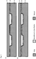
- Figure 1 Several examples are shown of surface that are in touching contact with a gas-permeable element within a fuel cell.
- Figure 1a a conventional planar surface of a substrate 1 of a bipolar plate and a fiber 2 of a gas-permeable element formed as a textile with fibers 2 without structuring according to the prior art is shown.
- Figure 1b shows a flat planar surface of a substrate 1 of a bipolar plate, which is coated with a layer 3 and a fiber 2 of a gas-permeable element rests on the surface.
- FIG. 1c An irregularly structured and with a layer 3 coated or modified surface of a substrate 1 of a bipolar plate, in which a fiber 2 of the gas-permeable element is arranged in a recess of the structure and the fiber 2 is in contact with 20% of its circumference in the region of the recess Contact with the structured surface of the substrate 1 of the bipolar plate is in Figure 1c shown.
- FIGS. 1d and 1e Examples of a regularly structured surface of a substrate 1 of a bipolar plate are to be illustrated.
- several depressions are formed in the surface of the substrate 1 of the bipolar plate in a form not shown.
- the depressions are each dimensioned the same, aligned in the same direction and formed at the same intervals from one another.
- At least part of a fiber surface of a gas-permeable element designed as a textile structure is inserted into each recess, so that there the surface of fibers 2 with at least 20% of their outer circumferential surface on the surface of the bipolar plate 1 (see Fig. Fig. 1e ) or the surface of a layer 3 or surface modification which has been formed on the surface of the substrate 1 of the bipolar plate is in touching contact.
- Layers 3 as they are in the Figures 1b to 1d can be used as follows for the Figures 3a to 3g still to be described, as a layer system 3, several layers formed one above the other or in the surface diffused or implanted elements or a combination thereof.
- FIG. 2a shows schematically the surface 3 of a substrate 1 of a bipolar plate with a smooth structure which, due to a manufacturing or assembly inaccuracy, does not have contact everywhere with the GDL 2, which is formed, for example, with fibers 2.1, the membrane unit of an electrochemical cell. This deteriorates the electrical current transfer.
- the GDL 2 with the fibers 2.1 can adapt better to a structured surface and thus has better contact with the modified surface 3.
- Figure 3a a bipolar plate with a substrate 1 made of a stainless steel 1.4404, on the surface of which is in touching contact with the gas-permeable element 2 when an electrochemical cell has been mounted, a layer system is arranged. After cleaning the surface of impurities and oxides z. B. by means of metal ion sputtering, chromium is deposited by means of a PVD process, for example by means of an arc evaporator.
- chromium layer 7 at temperatures between 200 ° C - 500 ° C, carbon is evaporated as an adhesion-promoting component by means of a pulsed or DC arc evaporator and ionized with high negative bias voltages (eg 1000 V) is implanted or subplanted. As a result, a carbon-rich surface layer or a carbon layer 5 obtained by subplantation is formed. Using a pulsed arc evaporator, highly ionized carbon is then deposited at lower bias voltages (eg ⁇ 500 V). Based on the high degree of ionization and the high energies of the impinging ions as well as the resulting surface tension and the temperature, a highly conductive nano- or micro-structured carbon layer 4 is formed on the surface.
- high negative bias voltages eg 1000 V
- the layer system or the surface modifications in the Figures 3a to 3g On a substrate surface of a bipolar plate, depressions and / or elevations can be formed on a structured surface, but this is not shown in these illustrations.
- the layers 4, 5, 6, 7, 8 and 9 are each shown on a flat strip surface of a substrate 1 before a forming process. But you can also click on already formed Substrates 1 for bipolar plates can be realized.
- the chromium passivation layer 8 is not completely removed but only partially converted near the surface, so that the oxygen content is reduced. This can be done by annealing in a hydrogen atmosphere, but also by etching processes.
- the carbon layer 5 is then implanted or subplanted into the chromium-rich former chromium oxide passivation layer 8, as described above, without a chromium intermediate layer 7.
- a very carbon-rich surface is formed on the surface of the former oxide layer, in which parts of the metal with which the substrate 1 is formed can still be found, the relative chromium and nickel content being increased and oxygen being additionally present.
- the chromium oxide passivation layer 8 is completely or at least 80% removed before the coating, e.g. by means of an etching process, and a carbon layer 5 obtained by subplantation with a thickness of ⁇ 20 nm is then applied as described above.
- the carbon layer 4 described in example 3a is deposited thereon (layer thickness 10-80 nm).
- the described chromium passivation layer 8 is applied to a surface that has been cleaned or partially converted as explained in example 3b, so that the oxygen content is reduced.
- a carbon layer 4 is then applied without first implanting or sublating carbon.
- Example 3e is a typical plasma nitrocarburized surface.
- prior plasma etching was dispensed with here.
- the edge layer 6 is partially converted by the simultaneous sub- or implantation of carbon and nitrogen ions. This also results in a certain cleaning effect, e.g. for existing water skins or organic material. Close to the surface, high carbon concentrations are achieved with moderate nitrogen introduction. The nitrogen ionization can thereby through a glow discharge in a nitrogen atmosphere excited by electrons from an arc evaporator.
- Carbon evaporators but also chromium evaporators or other arc-evaporating substances can be used for this purpose.
- the nitrogen ions and the carbon ions are accelerated to the surface by high bias voltages (eg 1000V).
- the processes can be carried out simultaneously or one after the other.
- the ions, in particular the carbon ions can be used to ionize the nitrogen and also to advantageously support diffusion into the metal surface. If possible, only thin edge layers 6 in the range ⁇ 100 nm should be treated. As few metal ions as possible should remain on the surface. In all nitriding operations or carbon implantation processes, the excessive formation of CrN or CrC should be avoided by using a suitable temperature regime.
- a pure nitriding process takes place without carbon, as described in example 3e. This is carried out longer so that greater depths of penetration can result.
- This edge layer 9 formed by nitriding then enables the firmly adhering deposition of a carbon layer 4, as described in example 3a.
- a previous removal or conversion of a passivation layer 8, if necessary, can again be dispensed with.
- Such layers can then also be implemented at depths of up to 5 ⁇ m. In all nitriding operations, the excessive formation of CrN should be avoided by using a suitable temperature regime.
- Fig. 3g is the shift system according to Figure 3f supplemented by an intermediate layer 7 made of chromium, for example 40 nm. This is deposited as described in FIG. 3a.
- Intermediate layers 7 made of chromium can be used in particular in the case of steels with a lower chromium content in order to ensure adequate corrosion resistance in the event of damage to the cover layer (cracks, scratches, etc.).
- Chromium intermediate layers 7 of this type can also be used in the case of laser weld seams in order to include a weld seam upper bead To alloy chrome.
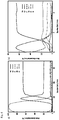
- Figure 4a shows the schematic XPS element analysis of a GLC layer system as it is in Fig. 3a is shown schematically in cross section.
- the entire layer system should preferably be implemented in a thickness range of 100 nm with a thin adhesive layer 7 made of chromium. All processes can be carried out in a pressure range of 10 -1 - 10 -3 mbar.
- the carbon content is almost 100%.
- This carbon layer 5 also results in a mixed layer of chromium and carbon or, in areas remote from the surface, layers which can be formed from Cr, C, Fe and other alloy components of the starting material.
- a typical XPS element analysis of a PNC surface treatment shows Figure 4b . Characteristically, the carbon content of the carbon layer 5 obtained by subplantation is lower than that of a pure carbon layer 4.
Description
Die Erfindung betrifft eine Bipolarplatte für elektrochemische Zellen, insbesondere für Polymerelektrolytbrennstoffzellen bzw. Proton-Exchange-Membrane- (PEM)-Brennstoffzellen sowie ein Herstellungsverfahren. Brennstoffzellen werden für die Gewinnung elektrischer Energie aus einem Brennstoff und einem Oxidationsmittel durch eine elektrochemische Reaktion eingesetzt. Insbesondere bei mobilen Anwendungen, wie z.B. in Fahrzeugen sind Proton-Exchange-Membrane- (PEM) Brennstoffzellen (PEMFC) geeignet. Es besteht aber auch die Möglichkeit elektrochemische Zellen so zu betreiben, dass mit elektrischer Energie eine elektrochemische Reaktion initiiert wird, bei der Wasserstoff als ein Reaktionsprodukt erhalten werden kann. Nachfolgend soll jedoch generell der Begriff Brennstoffzelle benutzt werden, wobei natürlich auch andere elektrochemische Zellen unter diesen Begriff verstanden werden sollen.The invention relates to a bipolar plate for electrochemical cells, in particular for polymer electrolyte fuel cells or proton exchange membrane (PEM) fuel cells, and a manufacturing method. Fuel cells are used to generate electrical energy from a fuel and an oxidizing agent through an electrochemical reaction. Proton Exchange Membrane (PEM) fuel cells (PEMFC) are particularly suitable for mobile applications, such as in vehicles. However, there is also the possibility of operating electrochemical cells in such a way that an electrochemical reaction is initiated with electrical energy, in which hydrogen can be obtained as a reaction product. In the following, however, the term fuel cell is to be used in general, with other electrochemical cells naturally also being understood by this term.
Bipolarplatten (BiP) dienen in der Brennstoffzelle der Zufuhr von Wasserstoff, Sauerstoff und der Ableitung von Wasser, Kühlwasser sowie dem Abgreifen von freiwerdenden Elektronen von den Elektroden der jeweiligen Brennstoffzelle, um eine elektrische Spannung zur Verfügung zu stellen.Bipolar plates (BiP) are used in the fuel cell to supply hydrogen, oxygen and to drain water and cooling water as well as to pick up electrons released from the electrodes of the respective fuel cell in order to provide an electrical voltage.
Eine Brennstoffzelle liefert zwischen den beiden Elektroden eine elektrische Nutzspannung von 0,5 V - 2,0 V. Es ist wichtig, dass die infolge der elektrochemischen Reaktion frei werdenden Elektronen auf der Wasserstoffseite (Anodenseite) möglichst effizient aufgenommen und auf der Sauerstoffseite (Kathodenseite) dem Prozess wieder möglichst effizient zugeführt werden können. Dies bedeutet, dass möglichst kleine elektrische Kontakt- oder Durchtrittswiderstände auftreten. Ein elektrischer Widerstand an dieser Stelle hat direkten Einfluss auf die Effizienz der BiP und somit der Brennstoffzelle.A fuel cell supplies a useful electrical voltage of 0.5 V - 2.0 V between the two electrodes. It is important that the electrons released as a result of the electrochemical reaction are absorbed as efficiently as possible on the hydrogen side (anode side) and on the oxygen side (cathode side). can be fed back into the process as efficiently as possible. This means that the lowest possible electrical contact or passage resistance occurs. An electrical resistance at this point has a direct influence on the efficiency of the BiP and thus the fuel cell.
Zwischen einer Bipolarplatte und der Membran, als Festelektrolyt, ist ein gasdurchlässiges Element angeordnet, das auch als Gas Diffusion Layer (GDL) bezeichnet werden kann, und das z.B. ein textiles offenporöses Gebilde ist, das bevorzugt aus bzw. mit elektrisch leitenden Fasern, insbesondere Kohlenstofffasern gebildet ist. Ein gasdurchlässiges Element erfüllt die Aufgaben der möglichst vollflächigen, homogenen Verteilung von aus Kanälen einer BiP austretendem Gas auf der Oberfläche der Membran und der Weiterleitung der vom Wasserstoff als Brennstoff abgegebenen Elektronen an die BiP und die von der BiP zugeführten Elektronen an das sich bildende Wasser auf der Oxidationsmittelseite weiterzuleiten.Between a bipolar plate and the membrane, as a solid electrolyte, a gas-permeable element is arranged, which can also be referred to as a gas diffusion layer (GDL) and which is, for example, a textile, open-pore structure, which is preferably made of or with electrically conductive fibers, in particular carbon fibers is formed. A gas-permeable element fulfills the tasks of distributing gas emerging from channels of a BiP as homogeneously as possible on the surface of the membrane and forwarding the electrons given off by the hydrogen as fuel to the BiP and the electrons supplied by the BiP to the water being formed to forward the oxidizing agent side.
Um den elektrischen Übergangswiderstand für die Elektronen (und damit die Verluste) möglichst gering zu halten, sollte einerseits der elektrische Kontaktwiderstand der BiP möglichst gering sein, andererseits muss die GDL mit hoher Flächenpressung gegen die BiP gepresst werden, um möglichst viele Kontaktpunkte und damit elektrische Strompfade zu bilden. Gleichzeitig muss anfallendes Prozesswasser abgeführt werden bzw. die Membraneinheit befeuchtet werden. Es ist bekannt, dass der elektrische Kontaktwiderstand (und damit der Verlust) mit steigender Flächenpressung sinkt. Die Flächenpressung kann aber nicht beliebig gesteigert werden, da dann die Membran und die BiP, die vorteilhaft aus einem möglichst dünnen Metallblech, bevorzugt einem Edelstahlblech gebildet ist, mechanisch Schaden nehmen.In order to keep the electrical contact resistance for the electrons (and thus the losses) as low as possible, on the one hand the electrical contact resistance of the BiP should be as low as possible, on the other hand the GDL must be pressed against the BiP with high surface pressure in order to create as many contact points and thus electrical current paths as possible to build. At the same time, any process water must be drained off or the membrane unit must be moistened. It is known that the electrical contact resistance (and thus the loss) decreases with increasing surface pressure. However, the surface pressure cannot be increased at will, since then the membrane and the BiP, which is advantageously formed from a metal sheet as thin as possible, preferably a stainless steel sheet, are mechanically damaged.
Der Kontaktwiderstand der BiP kann durch Oberflächenmodifikation des für die Herstellung einer BiP eingesetzten Metalls (z.B. rost- und säurebeständige, Stähle) gesenkt werden. Bei ausreichendem Korrosionsschutz durch eine Oberflächenmodifikation ist es auch denkbar Metalle mit geringerem Rost- und Korrosionsschutz einzusetzen. Hierfür gibt es verschiedene Möglichkeiten:
Der elektrische Übergangswiderstand ist üblicherweise aufgrund der natürlichen, schlecht leitenden Passivschicht an der Oberfläche des Metalls, insbesondere z.B. bei rost- und säurebeständigem Stahl in Form einer Chromoxidschicht relativ groß. Eine mechanische, chemische und/oder physikalische Entfernung einer Passivschicht vor Inbetriebnahme bringt keine befriedigende Verbesserung und diese regeneriert sehr schnell.The contact resistance of the BiP can be reduced by surface modification of the metal used for the production of a BiP (e.g. rust and acid-resistant steels). With sufficient corrosion protection through surface modification, it is also conceivable to use metals with less rust and corrosion protection. There are various possibilities:
The electrical contact resistance is usually relatively high due to the natural, poorly conductive passive layer on the surface of the metal, in particular, for example, in the case of rust- and acid-resistant steel in the form of a chromium oxide layer. A mechanical, chemical and / or physical removal of a passive layer before start-up does not bring any satisfactory improvement and it regenerates very quickly.
Durch Erhöhung des Anpressdrucks an eine BiP wird die GDL verdichtet und stärker an die Oberfläche der BiP gedrückt. Der Erhöhung des Anpressdrucks sind jedoch aufgrund der Empfindlichkeit der Membran, der Notwendigkeit, die GDL nicht zu sehr zu verdichten, um eine ausreichende Gasdiffusion zu gewährleisten und der mechanischen Stabilität der BiP Grenzen gesetzt. Die mechanische Stabilität der BiP Platte kann hierbei allerdings, wie im Weiteren beschrieben, durch eine geeignete Oberflächenveredelung erhöht werden.By increasing the contact pressure on a BiP, the GDL is compressed and pressed more strongly against the surface of the BiP. However, due to the sensitivity of the membrane, the need not to compress the GDL too much in order to ensure sufficient gas diffusion and the mechanical stability of the BiP, there are limits to the increase in the contact pressure. The mechanical stability of the BiP plate can, however, as described below, be increased through a suitable surface finish.
Beispielsweise ist eine solche Oberflächenmodifkation sowohl in der Veröffentlichung
In den Dokumenten
In the documents
Die einzelnen, oben beschriebenen Maßnahmen reduzieren den Kontaktwiderstand entweder nur unzureichend, sind kostspielig oder führen zu Nachteilen bezüglich der chemischen und/oder physikalischen Stabilität, Zuverlässigkeit oder Haltbarkeit der Brennstoffzelle.The individual measures described above either only insufficiently reduce the contact resistance, are expensive or lead to disadvantages with regard to the chemical and / or physical stability, reliability or durability of the fuel cell.
Es ist daher Aufgabe der Erfindung, Möglichkeiten für eine dauerhafte Reduzierung des elektrischen Kontakt- und/oder Überganswiderstands zwischen einer Oberfläche einer Bipolarplatte, die aus einem Edelstahl gebildet ist, und einem gasdurchlässigen Element (GDL) einer Brennstoffzelle, die in berührendem Kontakt miteinander stehen, anzugeben, wobei die Kosten für die Herstellung in einem vertretbaren Rahmen gehalten werden können.It is therefore the object of the invention to provide possibilities for a permanent reduction in the electrical contact and / or transition resistance between a surface of a bipolar plate made of stainless steel and a gas-permeable element (GDL) of a fuel cell that are in touching contact with one another, to be stated, whereby the cost of production can be kept within reasonable limits.
Erfindungsgemäß wird diese Aufgabe mit einem Herstellungsverfahren, das die Merkmale des Anspruchs 1 aufweist, gelöst. Vorteilhafte Ausgestaltungen und Weiterbildungen können mit in untergeordneten Ansprüchen bezeichneten Merkmalen realisiert werden.According to the invention, this object is achieved with a production method which has the features of
Die erfindungsgemäße Bipolarplatte für elektrochemische Zellen, insbesondere für Proton-Exchange-Membrane- (PEM) Brennstoffzellen, ist mit einem metallischen Substrat gebildet. An der Oberfläche ist das Substrat mit einer den elektrischen Kontaktwiderstand verringernden kohlenstoffbasierten Schicht, einem Schichtsystem oder einer Grenzschicht, die aus einer oberflächennahen hauptsächlich sp2-gebundenen kohlenstoffbasierten Schicht mit einem Kohlenstoffanteil im Bereich 50 % bis 100 % gebildet ist, die auf einer gegenüber dem Ausgangsmaterial modifizierten metallischen Oberfläche des Substrats aufgebracht ist, versehen.The bipolar plate according to the invention for electrochemical cells, in particular for proton exchange membrane (PEM) fuel cells, is formed with a metallic substrate. On the surface, the substrate is provided with a carbon-based layer that reduces the electrical contact resistance, a layer system or a boundary layer, which is formed from a mainly sp2-bonded carbon-based layer near the surface with a carbon content in the range 50% to 100%, which is on a layer compared to the starting material modified metallic surface of the substrate is applied, provided.
Es besteht auch die Möglichkeit, dass zwischen der kohlenstoffbasierten Schicht oder der mit Kohlenstoff angereicherten Schicht und der Oberfläche des Substrats eine Übergangszone mit einem Kohlenstoffgradienten ausgebildet ist.There is also the possibility that a transition zone with a carbon gradient is formed between the carbon-based layer or the layer enriched with carbon and the surface of the substrate.
Einzelne Erhebungen und/oder Vertiefungen sollten an der Oberfläche des Substrats so dimensioniert und geometrisch gestaltet sein, dass Fasern, mit denen das gasdurchlässige Element als textiles Gebilde gebildet ist, über ihren äußeren Umfang mit mindestens 10 % ihrer äußeren Mantelfläche in berührenden Kontakt, in einem Bereich der Oberfläche des Substrats in dem eine Vertiefung vorhanden ist und in dem sich eine Faser und die Oberfläche des Substrats berühren, in berührendem Kontakt stehen; wobei bevorzugt Vertiefungen in der Oberfläche des Substrats mit gleicher Ausrichtung und in konstanten Abständen zwischen nebeneinander angeordneten Vertiefungen ausgebildet sind.Individual elevations and / or depressions should be dimensioned and geometrically designed on the surface of the substrate so that fibers with which the gas-permeable element is formed as a textile structure are in touching contact over their outer circumference with at least 10% of their outer surface area, in one Area of the surface of the substrate in which a depression is present and in which a fiber and the surface of the substrate touch, are in touching contact; wherein depressions are preferably formed in the surface of the substrate with the same orientation and at constant intervals between depressions arranged next to one another.
Ein metallisches Substrat kann an der Oberfläche, die mit einem gasdurchlässigen Element innerhalb der elektrochemischen Zelle in berührendem Kontakt steht, eine Strukturierung, die mit Erhebungen und/oder Vertiefungen in der jeweiligen Oberfläche gebildet ist, aufweisen.On the surface that is in touching contact with a gas-permeable element within the electrochemical cell, a metallic substrate can have a structure which is formed with elevations and / or depressions in the respective surface.
Bei dem Verfahren zur Herstellung einer Bipolarplatte wird so vorgegangen , dass
- eine Strukturierung der mit einem gasdurchlässigen Element in Kontakt stehenden Oberfläche eines Substrats, die mit einem gasdurchlässigen Element in einer Brennstoffzelle in berührendem Kontakt steht, mit Erhebungen und/oder Vertiefungen an dieser Oberfläche ausgebildet wird. Dies kann mittels Werkstoffabtrag und/oder durch ein Prägeverfahren erreicht werden. Desweiteren wird vor der Strukturierung mindestens einer der nachfolgenden zwei Schritte durchgeführt:
- Die jeweilige Oberfläche des Substrats wird mit einer graphitischen Schicht, die bevorzugt vollständig geschlossen mit mehreren übereinander angeordneten Atomlagen gebildet ist, im Vakuum mittels eines Plasma, das bevorzugt mit einer elektrischen Bogenentladung generiert wird, beschichtet.
- Es wird eine Randschicht an der jeweiligen Oberfläche des Substrats durch ein Nitrier-, ein Carburier- oder ein Carbonitrierverfahren bei Einhaltung einer dafür geeigneten Atmosphäre mittels eines Plasma ausgebildet, wobei bevorzugt bei einem Carbonitrieren zuerst eine Nitrierung und nachfolgend eine Carburierung der Randschicht durchgeführt wird.
- a structuring of the surface of a substrate which is in contact with a gas-permeable element and which is in touching contact with a gas-permeable element in a fuel cell is formed with elevations and / or depressions on this surface. This can be achieved by removing material and / or by an embossing process. Furthermore, at least one of the following two steps is carried out before structuring:
- The respective surface of the substrate is coated with a graphitic layer, which is preferably formed completely closed with a plurality of atomic layers arranged one above the other, in a vacuum by means of a plasma, which is preferably generated with an electric arc discharge.
- An edge layer is formed on the respective surface of the substrate by a nitriding, carburizing or carbonitriding process while maintaining a suitable atmosphere by means of a plasma, with carbonitriding preferably firstly nitriding and then carburizing the edge layer.
Vorteilhaft kann eine Erhöhung der Rauheit und der spezifischen Oberfläche der Oberfläche des Substrats, die mit einem gasdurchlässigen Element in berührenden Kontakt innerhalb einer Brennstoffzelle steht, mittels eines Ätzverfahrens erreicht werden.An increase in the roughness and the specific surface of the surface of the substrate which is in touching contact with a gas-permeable element within a fuel cell can advantageously be achieved by means of an etching process.
Günstig ist es vor dem Aufbringen einer graphitischen kohlenstoffbasierten Schicht, einem Schichtsystem oder einer Grenzschicht oder der Ausbildung einer Randschicht eine auf der Oberfläche des Substrats vorhandene Oxidschicht zumindest teilweise zu entfernen. Die Entfernung kann bevorzugt mittels eines Ätzprozesses in Argon, Stickstoff oder eine Reduzierung des Oxids in einer besonders bevorzugt wasserstoffhaltigen Atmosphäre durchgeführt werden. Dabei kann eine vollständige Entfernung einer Oxidschicht vorteilhaft sein. Insbesondere bei Chromoxidschichten kann aber eine teilweise Entfernung vorteilhaft sein. Es kann eine partielle Umwandlung des Chromoxids genutzt werden, um z.B. bei rost- und säurebeständigen Stählen, die Anreicherung des die Passivierungsschicht bildenden Metalls, z.B. Chrom dort für den Korrosionsschutz im Verletzungsfall der darüber liegenden Kohlenstoff- und Stickstoff reichen Zone, auszunutzen.Before applying a graphitic carbon-based layer, a layer system or a boundary layer or the formation of an edge layer, it is advantageous to at least partially remove an oxide layer present on the surface of the substrate. The removal can preferably be carried out by means of an etching process in argon, nitrogen or a reduction of the oxide in a particularly preferably hydrogen-containing atmosphere. Complete removal of an oxide layer can be advantageous here. However, partial removal can be advantageous, particularly in the case of chromium oxide layers. A partial conversion of the chromium oxide can be used, e.g. in the case of rust and acid-resistant steels, to utilize the enrichment of the metal forming the passivation layer, e.g. chromium there for protection against corrosion in the event of damage to the carbon and nitrogen-rich zone above.
In einer Ausführungsform kann eine Haftvermittlerschicht, bevorzugt als dünne Schicht aus Chrom, Titan oder einer Schicht, die mit Chrom und Titan gebildet ist, vor dem Aufbringen der graphitischen kohlenstoffbasierten Schicht, einem Schichtsystem oder einer Grenzschicht bevorzugt mittels einer elektrischen Bogenentladungsprozesses im Vakuum auf der Substratoberfläche ausgebildet werden.In one embodiment, an adhesion promoter layer, preferably as a thin layer of chromium, titanium or a layer formed with chromium and titanium, can be applied to the substrate surface before the graphitic carbon-based layer, a layer system or a boundary layer is applied, preferably by means of an electric arc discharge process in a vacuum be formed.
Die graphitische kohlenstoffbasierte Schicht, ein Schichtsystem oder eine Grenzschicht kann mit ionisierten und beschleunigten Kohlenstoffionen, die auf der Oberfläche des Substrats vorhanden Kohlenstoffatome bei Temperaturen im Bereich 80 °C bis 600 °C, bevorzugt im Bereich 200 °C bis 500°C auftreffen, insbesondere mit einer Schichtdicke < 80 nm ausgebildet werden. Dabei kann eine zumindest nahezu 100 %-ige Ionisierung des Kohlenstoffs mittels eines Pulsbogenverdampfers erreicht werden. Dabei ist es vorteilhaft, dass hoch ionisierte und beschleunigte Kohlenstoffionen auf Kohlenstoffatome auf der Oberfläche bei den erhöhten Temperaturen auftreffen. Die Schicht sollte hierbei auf eine Kohlenstoff sublantierte Schicht aufgebracht werden. Um einen Austritt von Metallionen zu minimieren und damit eine Vergiftung der Membraneinheit zu verhindern, sollten keine metallischen Bestandteile eingebaut sein. Die Biasspannung sollte hierbei niedriger als bei einer Sublantation gewählt sein.The graphitic carbon-based layer, a layer system or a boundary layer can, with ionized and accelerated carbon ions, which carbon atoms present on the surface of the substrate, strike at temperatures in the
Bei der gleichzeitigen Sublantation- bzw. Implantation von Kohlenstoff und Stickstoff, in einem Bandlauf, können die Elektronen eines Verdampfers für Kohlenstoff, bevorzugt eines Lichtbogenverdampfers, im Vakuum genutzt werden, um mit Hilfselektroden Stickstoff zu ionisieren. Die Stickstoffionen können dann mit einer Biasspannung Richtung Blechoberfläche beschleunigt werden. Gleichzeitig kann der hochionisierte Kohlenstoff der Verdampfer mit gleicher Biasspannung ebenfalls in die Metalloberfläche eingebracht werden.With the simultaneous sublantation or implantation of carbon and nitrogen in a belt run, the electrons of an evaporator for carbon, preferably an arc evaporator, can be used in a vacuum to ionize nitrogen with auxiliary electrodes. The nitrogen ions can then be accelerated towards the sheet metal surface with a bias voltage. At the same time, the highly ionized carbon of the evaporator can also be introduced into the metal surface with the same bias voltage.
Der Diffusionsprozess des Stickstoffs in die Tiefe des Substratwerkstoffs kann durch auftreffende Kohlenstoffionen oder der Diffusionsprozess des Kohlenstoffs durch auftreffende Stickstoffionen beschleunigt werden. Bei einem solchen Prozess kann auch auf die Entfernung der Chromoxidschicht verzichtet werden.The diffusion process of nitrogen into the depth of the substrate material can be accelerated by impacting carbon ions or the diffusion process of carbon by impacting nitrogen ions. With such a process, the removal of the chromium oxide layer can also be dispensed with.
Das Plasmanitrocarborieren zur Ausbildung der Randschicht kann dabei in einer vakuumnahen Stickstoff enthaltenden Atmosphäre, bei einem Druck im Bereich 10-1 mbar bis 10-3 mbar durch eine Nitrierbehandlung bei der Stickstoffionen in Richtung Substratoberfläche beschleunigt werden, durchgeführt werden. Dabei ist bevorzugt am Substrat eine elektrisch negative Biasspannung im Bereich 500 V bis 1000 V angelegt oder das Substrat ist an Erdpotential angeschlossen. Es sollte eine Temperatur im Bereich 350 °C - 500°C eingehalten sein.The plasma nitrocarburizing to form the edge layer can be carried out in an atmosphere containing nitrogen close to vacuum, at a pressure in the
Plasmanitrocarborierte Schichten können als harte Randschichten so ausgebildet werden, dass ein höherer Anpressdruck auf die Bipolarplatte ausgeübt werden kann und damit verbesserte elektrische Kontaktwiderstände erzielbar sind. Es können statt höherer Anpressdrücke auch dünnere Bleche als Substrate bei gleichen Anpressdrücken verwendet werden. Plasmanitrocarburierte Oberflächen können auch als korrosionsfeste Oberflächen mit guter Haftung für Kohlenstoffschichten genutzt werden.Plasma nitrocarborized layers can be designed as hard outer layers in such a way that a higher contact pressure is exerted on the bipolar plate can be and thus improved electrical contact resistances can be achieved. Instead of higher contact pressures, thinner metal sheets can also be used as substrates with the same contact pressures. Plasma nitrocarburized surfaces can also be used as corrosion-resistant surfaces with good adhesion for carbon layers.
Oberflächenschichtsysteme oder-strukturierungen können, ohne gravierende Einbußen in der Performance in der Brennstoffzelle in einem Bandveredelungsprozess hergestellt werden und danach kann das entsprechend behandelte bandförmige Substratmaterial zu Bipolarplatten umgeformt werden. Hierbei können Randschichten in der Zone höchster Umformgrade gereckt und ausgedünnt werden.Surface layer systems or structures can be produced in a strip finishing process without serious losses in performance in the fuel cell and then the appropriately treated strip-shaped substrate material can be formed into bipolar plates. Here, edge layers can be stretched and thinned in the zone of the highest degree of deformation.
Aufgrund der Oberflächenmodifizierung an Substratoberflächen können preiswertere Substratwerkstoffe eingesetzt werden.Because of the surface modification on substrate surfaces, cheaper substrate materials can be used.
Vertiefungen in der strukturierten Substratoberfläche können unregelmäßig ausgebildet sein. Bevorzugt sind sie aber mit gleicher Ausrichtung und in konstanten Abständen zwischen nebeneinander angeordneten Vertiefungen ausgebildet. Vorteilhafterweise können diese Vertiefungen oder Oberflächenstrukturen so ausgeprägt sein, das in Bereichen der BiP die nicht in unmittelbarem Kontakt zur GDL stehen, eine Vorzugsflussrichtung von Reaktionsprodukten des Brennstoffzellenprozesses aus dem aktiven Bereich existiert. In diesem Ausführungsbeispiel würde die Oberflächenstruktur anisotrope Eigenschaften aufweisen und entsprechend ausgeführt sein. Weiterhin können vorteilhafte Eigenschaften einer derartigen Strukturierung darin bestehen, dass bei nicht regelmäßigem Kontakt zwischen GDL und BiP und damit fehlendem elektrisch leitendem Kontakt oder einem reduzierten Anpressdruck zwischen GDL und BiP, eine verbesserte elektrische Kontaktierung möglich wird.Depressions in the structured substrate surface can be formed irregularly. However, they are preferably designed with the same orientation and at constant intervals between depressions arranged next to one another. These depressions or surface structures can advantageously be so pronounced that in areas of the BiP that are not in direct contact with the GDL there is a preferred flow direction of reaction products of the fuel cell process from the active area. In this exemplary embodiment, the surface structure would have anisotropic properties and be designed accordingly. Furthermore, advantageous properties of such a structuring can consist in the fact that improved electrical contacting becomes possible if the contact between GDL and BiP is not regular and therefore there is no electrically conductive contact or a reduced contact pressure between GDL and BiP.
Auf der Oberfläche, die mit dem gasdurchlässigen Element in berührendem Kontakt steht und strukturiert und/oder mit erhöhter Rauheit ausgebildet ist, kann zur weiteren Erhöhung der elektrischen Leitfähigkeit bzw. einer Reduzierung des elektrischen Kontaktwiderstandes eine Schicht oder Randzone, die bevorzugt mit aus amorph graphitischem oder nano- bzw. mikrostrukturiertem Kohlenstoff gebildet ist, aufgebracht sein. Allein oder zusätzlich dazu kann eine Randschicht an der Oberfläche der BiP, die mit Nitrid und/oder Kohlenstoff, durch Nitrieren und/oder Carburieren, insbesondere durch Plamsanitrocarbirieren gebildet ist, ausgebildet sein.On the surface that is in touching contact with the gas-permeable element and is structured and / or designed with increased roughness, a layer or edge zone, which is preferably made of amorphous graphitic or graphite, can be used to further increase the electrical conductivity or reduce the electrical contact resistance is formed nano- or microstructured carbon, be applied. Alone or in addition to it For example, an edge layer can be formed on the surface of the BiP, which is formed with nitride and / or carbon, by nitriding and / or carburizing, in particular by plasma nitrocarburizing.
Eine graphitische Kohlenstoffschicht sollte bevorzugt vollständig geschlossen mit mehreren übereinander bzw. bevorzugt nebeneinander insbesondere senkrecht zur BiP-Oberfläche, angeordneten Atomlagen bzw. Strukturen gebildet sein. Sie kann im Vakuum mittels eines Plasmas, das bevorzugt mit einer elektrischen Bogenentladung generiert wird, ausgebildet werden. Bevorzugt ist das Plasma als Pulsplasma mit nahezu 100% lonisierungsgraden auszubilden. Hierbei sollte durch eine hohe Energieeinbringung und damit Temperatur des Prozesses bzw. externe Heizquellen sicher gestellt werden, dass sich die Kohlenstoffschichten graphitisch (sp2 Bindung) ausbilden. Beispielhaft sind dies Oberflächentemperaturen im Bereich 50°C -500°C, bevorzugt bei ca. 300 °C. Hohe Ionisierungen und anliegende Beschleunigungsspannungen (Bias) zwischen Verdampfer und Metalloberfläche des Substrates führen dazu, dass die Ionen mit hohen Energien bevorzugt > 100 eV auf Kohlenstoff an der Oberfläche auftreffen. Dies führt zu besonders vorteilhaften Strukturen der Kohlenstoffschichten bezüglich elektrischem Kontaktwiderstand und Haftfestigkeit. Für die Ausbildung sp2 gebundener Schichten mit niedrigem elektrischen Kontakt bzw. spezifischem Widerstand ist das Verhältnis aus Temperatur, Vakuumdruck (ggf. mit Prozessgas) und Beschleunigungsspannung der Kohlenstoffionen wichtig, wobei zu beachten ist, dass bei zu hohen Drücken die Ausbildung vorteilhaft elektrisch leitfähiger Schichten unterdrückt werden kann. Durch geeignete Parameterwahl können im Grenzwert auch geeignete Kohlenstoffschichten bei Raumtemperatur hergestellt werden.A graphitic carbon layer should preferably be formed completely closed with several atomic layers or structures arranged one above the other or preferably next to one another, in particular perpendicular to the BiP surface. It can be formed in a vacuum by means of a plasma, which is preferably generated with an electric arc discharge. The plasma is preferably designed as a pulsed plasma with almost 100% degrees of ionization. A high energy input and thus the temperature of the process or external heat sources should ensure that the carbon layers develop graphitically (sp2 bond). These are, for example, surface temperatures in the range 50 ° C-500 ° C, preferably around 300 ° C. High ionizations and applied acceleration voltages (bias) between the evaporator and the metal surface of the substrate mean that the ions with high energies, preferably> 100 eV, strike carbon on the surface. This leads to particularly advantageous structures of the carbon layers with regard to electrical contact resistance and adhesive strength. For the formation of sp2-bonded layers with low electrical contact or specific resistance, the ratio of temperature, vacuum pressure (possibly with process gas) and acceleration voltage of the carbon ions is important, whereby it should be noted that if the pressure is too high, the formation of electrically conductive layers is advantageously suppressed can be. By choosing suitable parameters, suitable carbon layers can also be produced at room temperature within the limit value.
Die Beschleunigungsspannung sollte hierbei typischerweise niedriger als bei vorlaufenden Kohlenstoff Sublantationsprozessen zur Steigerung der Haftfestigkeit gewählt werden. Vorteilhaft für eine besonders hohe Haftfestigkeit ist es vor der Kohlenstoffbeschichtung hoch ionisierten Kohlenstoff durch hohe Beschleunigungsspannungen (z.B. 1000 V) in die Oberfläche zu implantieren bzw. zu subplantieren. Derartige Schichten können wie im Falle einer plasmanitrocarburierten Schicht auch schon als Kohlenstoffelektrode (Schicht- bzw. Randschichtdicke 1 nm - 20 nm) verwendet werden.The acceleration voltage should typically be lower than in the case of preceding carbon sublimation processes to increase the adhesive strength. For a particularly high adhesive strength, it is advantageous to implant or subplant highly ionized carbon into the surface by means of high acceleration voltages (eg 1000 V) before the carbon coating. Such layers can, as in the case of a plasma nitrocarburized layer, also be used as a carbon electrode (layer or
Eine weitere graphitische Kohlenstoff-Deckschicht sollte möglichst dünn z.B. < 80 nm ausgeführt werden. Um einen Austritt von Metallionen zu minimieren und damit eine Vergiftung der Membraneinheit zu verhindern, sollten keine metallischen Bestandteile eingebaut sein.Another graphitic carbon top layer should be made as thin as possible, e.g. <80 nm. In order to minimize the escape of metal ions and thus prevent poisoning of the membrane unit, no metallic components should be installed.
Bedingt durch den Prozess der Bogenentladung im Vakuum können auch Kohlenstoffpartikel in der Schicht vorkommen bzw. kann es zu Defekten, wie z.B. Fehlstellen führen. Bei einer gefilterten Abscheidung z. B. mit einem magnetischen Filter oder der Abscheidung mittels alternativer PVD-Verfahren, wie z.B. einem Sputterprozess können auch nahezu partikelfreie Schichten mit Kohlenstoff hergestellt werden.Due to the process of arc discharge in a vacuum, carbon particles can also appear in the layer or it can lead to defects such as flaws. With a filtered deposition z. B. with a magnetic filter or the deposition by means of alternative PVD processes, such as a sputtering process, almost particle-free layers with carbon can also be produced.
Zwischen der strukturierten Oberfläche eines Substrats und einer Schicht oder einer Randschicht kann eine Zwischenschicht, insbesondere eine Chromschicht vorhanden sein, mit der die Haftung der Kohlenstoffschicht als auch die Korrosionsbeständigkeit der BiP verbessert werden kann. Insbesondere im Bereich von Rissen, lokalen Defekten bzw. Schweißnähten kann eine Chromzwischenschicht dafür sorgen, dass sich eine stabile Chrompassivierungsschicht ausbildet. Hierdurch kann die Korrosion aber auch der Austritt von Eisenionen, die die Membraneinheit einer elektrochemischen Zelle vergiften können, verhindert werden und die Umformeignung können verbessert werden. Tritt eine zu starke Kontamination der Membraneinheit durch Chromionen auf, kann die Chromschicht z.B. durch eine Titanschicht ersetzt werden. Es kann aber auch eine Zwischenschicht gewählt werden, die sowohl mit Chrom, wie auch mit Titan gebildet ist.An intermediate layer, in particular a chrome layer, with which the adhesion of the carbon layer and the corrosion resistance of the BiP can be improved, can be present between the structured surface of a substrate and a layer or an edge layer. In particular in the area of cracks, local defects or weld seams, an intermediate chromium layer can ensure that a stable chromium passivation layer is formed. In this way, the corrosion but also the escape of iron ions, which can poison the membrane unit of an electrochemical cell, can be prevented and the suitability for forming can be improved. If the membrane unit is excessively contaminated by chromium ions, the chromium layer can be replaced with a titanium layer, for example. However, an intermediate layer can also be selected which is formed with both chromium and titanium.
Als Reinigungsprozess zur Beseitigung der Oxidschichten vor dem Aufdampfen der Haftvermittlerschicht, bevorzugt einer Chromschicht, können die Oberflächen vorher z.B. durch Metallionensputtern gereinigt werden.As a cleaning process to remove the oxide layers before the vapor deposition of the adhesion promoter layer, preferably a chrome layer, the surfaces can be cleaned beforehand, e.g. by metal ion sputtering.
Eine Vorteilhafte Variante der Herstellung einer BiP besteht darin, die Beschichtungen und Oberflächenstrukturierungen an bandförmigem Material auszuführen und dieses bandförmige Material danach in nachfolgenden Prozessen umzuformen, in Form zu schneiden und zu verschweißen. Für einen solchen Bandprozess ist es vorteilhaft, das Band aus einem klassischen Bandglühprozess mit einer reduzierenden Atmosphäre (z.B. geeigneter Wasserstoffanteil) unter Schutzgasbedingungen heraus zu schleusen. Hier kann ohne zusätzliche Bearbeitungsschritte eine vollständige oder partielle Reduzierung der Oxidschicht z.B. Chromoxid gewährleistet und die Bandwärme kann im weiteren Prozessverlauf genutzt werden. In einer Vakuumkammer kann ein solcher Prozess durch Ätzen in einem wasserstoffhaltigen Gas durchgeführt werden.
Besonders vorteilhaft ist es die Chromanreicherung, die typischerweise bei Edelstahl in der passivierenden Zwischenschicht auftritt, nach einer reduzierenden Behandlung anstelle einer Chromhaftvermittlerschicht zu nutzen.An advantageous variant of the production of a BiP consists in executing the coatings and surface structuring on strip-shaped material and then reshaping this strip-shaped material in subsequent processes, cutting it into shape and welding it. For such a strip process, it is advantageous to use the strip from a classic strip annealing process with a reducing atmosphere (e.g. suitable hydrogen content) out under protective gas conditions. A complete or partial reduction of the oxide layer, for example chromium oxide, can be ensured here without additional processing steps and the strip heat can be used in the further course of the process. Such a process can be carried out in a vacuum chamber by etching in a hydrogen-containing gas.
It is particularly advantageous to use the chromium enrichment, which typically occurs in the passivating intermediate layer of stainless steel, after a reducing treatment instead of a chromium adhesion promoter layer.
Bei der Herstellung einer erfindungsgemäßen BiP kann so vorgegangen werden, dass eine Strukturierung der mit einem gasdurchlässigen Element in Kontakt stehenden Oberfläche einer BiP, die mit einem gasdurchlässigen Element (GDL) in einer Brennstoffzelle in berührendem Kontakt steht, mit Erhebungen und/oder Vertiefungen an dieser Oberfläche mittels Werkstoffabtrag und/oder durch ein Prägeverfahren ausgebildet wird. Die Strukturierung kann aber auch durch das Zusammenwirken der Oberflächenbehandlungen mit hohen Umformgraden des Bleches zur Ausbildung der Flussfeldgeometrie herbeigeführt werden.When producing a BiP according to the invention, the procedure can be that the structuring of the surface of a BiP which is in contact with a gas-permeable element and which is in touching contact with a gas-permeable element (GDL) in a fuel cell, with elevations and / or depressions on the latter Surface is formed by material removal and / or by an embossing process. The structuring can, however, also be brought about by the interaction of the surface treatments with high degrees of deformation of the sheet metal to form the flow field geometry.
Der Werkstoffabtrag kann mit mindestens einem Laserstrahl, bevorzugt durch Interferenz mehrerer Laserstrahlen in einem bestrahlten Bereich der jeweiligen Oberfläche der BiP erfolgen. Dabei kann vorteilhaft ein lokal definierter Werkstoffabtrag in sehr kurzer Zeit erreicht werden. So können verschiedenste Muster in definierter Form an der Oberfläche durch Strukturierung erhalten werden, so dass ein relativ hohes Maß an Flexibilität gegeben ist.The material can be removed with at least one laser beam, preferably by interference of several laser beams in an irradiated area of the respective surface of the BiP. A locally defined material removal can advantageously be achieved in a very short time. A wide variety of patterns can be obtained in a defined form on the surface by structuring, so that a relatively high degree of flexibility is given.
Die Rauheit und spezifische Oberfläche der jeweiligen Oberfläche eines Substrats für eine BiP können durch Beschuss mit Ionen, die bevorzugt eine Energie im Bereich 102 eV bis 75 ∗ 103 eV aufweisen, im Vakuum erhöht werden.The roughness and specific surface of the respective surface of a substrate for a BiP can be increased in a vacuum by bombardment with ions, which preferably have an energy in the range from 10 2 eV to 75 * 10 3 eV.
Eine Randschicht kann an der jeweiligen Oberfläche des Substrats einer BiP auch durch ein Nitrier-, ein Carburier oder ein Nitrocarborierverfahren bei Einhaltung einer dafür geeigneten Temperatur und Atmosphäre mittels eines Plasma ausgebildet werden. Bevorzugt kann eine Randschicht mittels Nitrocarborieren so erhalten werden, dass zuerst eine Nitrierung und nachfolgend eine Carburierung der Randschicht durchgeführt wird. Vorteilhaft ist hier, dass hierdurch auch zusätzlich harte Randschichten erzeugt werden, die die Verformung der Bipolarplatte im umgeformten Zustand behindern und hiermit den Einsatz dünnerer Bleche oder von höheren Anpressdrücke ermöglichen.An edge layer can also be formed on the respective surface of the substrate of a BiP by means of a nitriding, carburizing or nitrocarburizing process by means of a plasma while maintaining a suitable temperature and atmosphere. An edge layer can preferably be obtained by means of nitrocarburizing in such a way that nitriding is carried out first and then followed a carburization of the surface layer is carried out. It is advantageous here that this also creates additional hard edge layers which hinder the deformation of the bipolar plate in the deformed state and thus enable the use of thinner sheets or higher contact pressures.
Eine Verbesserung des elektrischen Stromübergangs von der GDL zur BiP ohne Erhöhung des Anpressdruckes kann durch Kombination einer Mikrostrukturierung der Oberfläche der BiPs mit einer chemischen Änderung (Beschichtung, Nitrierung) erzielt werden. Dadurch wird die Größe der Flächen, die in berührendem Kontakt zueinander stehen, vergrößert und dadurch kann der intrinsische elektrische Oberflächenwiderstand verringert werden.An improvement in the electrical current transfer from the GDL to the BiP without increasing the contact pressure can be achieved by combining a microstructuring of the surface of the BiPs with a chemical change (coating, nitriding). This increases the size of the areas that are in touching contact with one another, and thereby the intrinsic electrical surface resistance can be reduced.
Die Ausprägung der Strukturierung kann sowohl stochastisch sein, d h. zufällig beispielsweise durch einen Ätzprozess oder deterministisch durch eine Laserstrukturierung oder einen Prägeprozess. Besonders vorteilhaft ist hierbei die Kombination aus Werkstoffabtrag mittels Laserstrukturierung oder einem Prägeprozess sowie der darauffolgenden Ätzung der Substratoberfläche.The characteristics of the structuring can be stochastic, i.e. randomly, for example, through an etching process or deterministically through a laser structuring or an embossing process. The combination of material removal by means of laser structuring or an embossing process and the subsequent etching of the substrate surface is particularly advantageous here.
Der beschriebene Lösungsweg hat den Vorteil, dass geringere elektrische Kontaktwiderstände als mit Gold beschichtete Oberflächen erreicht werden können. Damit sind wesentliche Kostenersparnisse und Effizienzsteigerungen bei BiP möglich. Weitere Kostenersparnisse bei der Herstellung der Oberflächenstrukturen und der Randschichten liegen in der Ausführung der Prozessschritte in einem Bandprozess, insbesondere der Rolle zu Rolle Bearbeitung und der anschließenden Bearbeitung des veredelten Bandmaterials zu BiP bzw. Brennstoffzellen. Derartige, haftfeste Schichten können auf Bandmaterial hergestellt werden und anschließend umgeformt werden, ohne dass die Performance in der Brennstoffzelle deutlich verschlechtert wird.The approach described has the advantage that lower electrical contact resistances can be achieved than surfaces coated with gold. This enables significant cost savings and increases in efficiency with BiP. Further cost savings in the production of the surface structures and the edge layers lie in the execution of the process steps in a strip process, in particular roll-to-roll processing and the subsequent processing of the refined strip material into BiP or fuel cells. Such firmly adhesive layers can be produced on strip material and then reshaped without the performance in the fuel cell being significantly impaired.
Hierbei können die Randschichten in der Zone höchster Umformgrade gereckt und ausgedünnt werden. In diesen Bereichen kann es auch zur Ausprägung einer umformungsbedingten charakteristischen Rissstruktur der Beschichtung bzw. Randschicht kommen.Here, the edge layers can be stretched and thinned in the zone of the highest degree of deformation. In these areas, a characteristic crack structure of the coating or edge layer caused by deformation can also occur.
Oberflächenstrukturierungen und/oder Oberflächenschichten bzw. Oberflächenschichtsysteme können aufgrund ihrer elektrischen Eigenschaften und der Korrosionsschutzwirkung genutzt werden, um preisgünstigere Metalle in Brennstoffzellen einsetzen zu können. Dazu gehören z.B. Metallbänder aus 1.4301 oder auch ferritische Stähle.Surface structuring and / or surface layers or surface layer systems can be used due to their electrical properties and the corrosion protection effect in order to be able to use cheaper metals in fuel cells. These include, for example, metal strips made of 1.4301 or ferritic steels.
Weiterhin bietet die Kombination der Verfahren Oberflächenstrukturierung mit einer Oberflächenbeschichtung den Vorteil weiter reduzierte elektrische Kontakt- und Übergangswiderstände als auch einen erhöhten Korrosionswiderstand durch die Oberflächenfunktionalisierung zu ermöglichen.Furthermore, the combination of the surface structuring process with a surface coating offers the advantage of enabling further reduced electrical contact and transition resistances as well as increased corrosion resistance through the surface functionalization.
Beispielhaft kann eine BiP folgender maßen hergestellt werden:
Die Strukturierung kann z. B. mittels eines ns-gepulst betriebenen Nd:YAG-Laserstrahls ausgebildet werden. Dieser Laserstrahl wird beispielsweise mit einer Pulslänge von 10 ns, einer Wellenlänge von 1064 nm und einer Pulsenergie von 1 J auf die Oberfläche gelenkt. Zwischen Laserquelle und Oberfläche der BiP kann der Laserstrahl zusätzlich über eine Laseroptik modifiziert werden. Dabei können z.B. durch Aufspalten des ursprünglichen Laserstrahles zwei Laserstrahlen erhalten werden, die auf der Oberfläche des Substrats wieder überlagert (interferieren) werden. Die Überlagerung und Fokussierung kann so erfolgen, dass in dem bestrahlten Gebiet Pulsenergiedichten (Laserfluenzen) von ca. 2 J/cm2 erreicht werden. Der Winkel zwischen den interferierenden Teillaserstrahlen kann so gewählt werden, dass die resultierende Interferenzperiode auf der Oberfläche 20 µm entspricht. Hierdurch können linienförmige Strukturen mit einer Periode von 20 µm erzeugt werden. Die Strukturtiefen liegen in diesem Fall bei ca. 1 µm - 10 µm.As an example, a BiP can be produced as follows:
The structuring can e.g. B. by means of an ns-pulsed Nd: YAG laser beam. This laser beam is directed onto the surface, for example with a pulse length of 10 ns, a wavelength of 1064 nm and a pulse energy of 1 J. The laser beam can also be modified using laser optics between the laser source and the surface of the BiP. For example, by splitting the original laser beam, two laser beams can be obtained, which are superimposed (interfering) again on the surface of the substrate. The superimposition and focusing can take place in such a way that pulse energy densities (laser fluences) of approx. 2 J / cm 2 are achieved in the irradiated area. The angle between the interfering partial laser beams can be chosen so that the resulting interference period on the surface corresponds to 20 µm. This enables linear structures with a period of 20 µm to be created. In this case, the structure depths are approx. 1 µm - 10 µm.
Beim Metalionensputtern zur Ausbildung einer Struktur auf der jeweiligen Oberfläche eines Substrats kann die jeweilige Oberfläche durch Beschuss von Ionen ausreichender Energie (102 eV bis mehreren 103 eV) abgetragen werden. Dem Zugrunde liegt ein Impulsübertrag eines auftreffenden Ions mit der Substratoberfläche. Durch elastische "Kernstöße" wird der Impuls in den Substratwerkstoff eingebracht und initiiert eine Stoßkaskade. Dadurch können Oberflächenatome einen nach außen gerichteten Impuls erhalten. Liegt die kinetische Energie der einfallenden Ionen über der Bindungsenergie der Atome des Substratwerkstoffs, können diese vorwiegend als einzelne Atome, aber auch in Form von Atomclustern, von der Substratoberfläche zerstäubt werden. Die Strukturtiefen liegen in diesem Fall bei ca. 0,05 µm - 2 µm.In metal ion sputtering to form a structure on the respective surface of a substrate, the respective surface can be removed by bombarding ions of sufficient energy (10 2 eV to several 10 3 eV). It is based on a momentum transfer of an impacting ion with the substrate surface. The impulse is introduced into the substrate material by elastic "core impacts" and initiates a cascade of impacts. This allows surface atoms to receive an outward momentum. Is the kinetic energy of the incident ions above the binding energy of the atoms of the substrate material, these can mainly be atomized as individual atoms, but also in the form of atom clusters, from the substrate surface. In this case, the structure depths are approx. 0.05 µm - 2 µm.
Durch Anlegen einer hohen elektrischen Spannung (Biasspannung) an das Substrat, das vorteilhaft in einer Vakuumkammer im Druckbereich von 10-5 mbar - 102 mbar angeordnet ist, wird ein Niederdruckplasma mit Hilfe von Edelgasen erzeugt. Mit einer Mischung von angeregten Metall- und Gasionen, können die erzeugten hochenergetischen Teilchen durch das angelegte elektrische Strompotential in Richtung der Substratoberfläche beschleunigt werden und es kann damit Werkstoff von der Oberfläche abgetragen werden. Hierdurch kann eine Plasmafeinreinigung der Oberfläche eines Substrats für eine BiP realisiert und die Oberflächenrauheit der so beeinflussten Oberfläche erhöht werden.By applying a high electrical voltage (bias voltage) to the substrate, which is advantageously arranged in a vacuum chamber in the pressure range of 10 -5 mbar - 10 2 mbar, a low-pressure plasma is generated with the aid of noble gases. With a mixture of excited metal and gas ions, the generated high-energy particles can be accelerated in the direction of the substrate surface by the applied electrical current potential and material can be removed from the surface. In this way, a plasma fine cleaning of the surface of a substrate for a BiP can be implemented and the surface roughness of the surface influenced in this way can be increased.
Eine strukturierte Oberfläche eines Substrats kann zusätzlich mit einer aus mindestens einer Schicht gebildeten Beschichtung versehen werden.A structured surface of a substrate can additionally be provided with a coating formed from at least one layer.
Prinzipiell ist eine Metallisierung metallischer Oberflächen zur Passivierung bekannt. So werden z.B. Metalloberflächen verzinkt oder verchromt, um sie langfristig vor Korrosion zu schützen. In der Brennstoffzelle treten zum Teil, je nach Betriebszustand, hohe Redoxpotentiale auf, die sehr aggressiv wirken und Schädigungen bzw. chemische Prozesse bewirken können. Werden BiP auf Metallbasis verwendet, können diese korrodieren. Das Ziel bei einer metallischen BiP ist es, die Korrosionsbeständigkeit zu erhöhen und eine gute elektrische Leitfähigkeit zu gewährleisten.In principle, metallization of metallic surfaces for passivation is known. For example, metal surfaces are galvanized or chrome-plated in order to protect them against corrosion in the long term. In some cases, depending on the operating status, high redox potentials occur in the fuel cell, which have a very aggressive effect and can cause damage or chemical processes. If metal-based BiP is used, it can corrode. The aim of a metallic BiP is to increase the corrosion resistance and to ensure good electrical conductivity.
Dies kann durch eine Abscheidung einer kohlenstoffbasierten, graphitähnlichen Schicht- bzw. eines solchen Schichtsystems erreicht werden.This can be achieved by depositing a carbon-based, graphite-like layer system or such a layer system.
Eine Beschichtung kann auch durch Modifizierung der Randschicht eines metallischen Substrats bzw. eines Metallbandes ausgebildet werden. Dies kann mittels Plasmanitrieren, als eine thermochemische Behandlung der Oberfläche von Stählen mit z.B. Stickstoff bei höheren Temperaturen (T =200 °C - 900° C) erreicht werden. Das Plasmanitrieren wird normalerweise zur Verbesserung der Verschleißeigenschaften eingesetzt. Speziell bei nichtrostenden Stählen kann durch das Abbinden von Chrom zu Chromnitrid (CrN) die korrosionsschützende Wirkung der sich immer wieder neu bildenden Passivierungsschicht aus Chromoxid verloren gehen.A coating can also be formed by modifying the edge layer of a metallic substrate or a metal strip. This can be achieved by means of plasma nitriding, as a thermochemical treatment of the surface of steels with, for example, nitrogen at higher temperatures (T = 200 ° C - 900 ° C). Plasma nitriding is normally used to improve wear properties. Especially with stainless steel When chromium sets to form chromium nitride (CrN), steels can lose the anti-corrosive effect of the passivation layer made of chromium oxide, which is constantly forming.
Vorteilhaft ist es, das Plasmanitrieren in Form hoch ionisierter und durch eine Biasspannung beschleunigter N-Ionen bei Temperaturen am Werkstück im Bereich 300 °C - 500°C durchzuführen. Eine geeignet Methode kann hierbei die bogengestützte Glimmentladung sein. Bei diesem Prozess werden mittels eines Bogenverdampfers Elektronen erzeugt und in Richtung auf eine zusätzliche gekühlte Anode beschleunigt, während entstehende Ionen abgeschirmt werden können. Angeregt durch den Elektronenstrom wird, bei Drücken im Bereich von 10-1 mbar - 10-3 mbar, Stickstoff oberhalb der zu behandelnden Oberfläche ionisiert und auf das entweder auf Erdpotential (Masse) oder mit einer negativen Biasspannung von ca. 200 V - 5000 V liegende Substrat beschleunigt. Die auf die Passivierungsschicht, bei austenitischen Stählen bevorzugt eine Chromoxidschicht, auftreffenden N-Ionen können oberflächennah implantiert / sublantiert werden bzw. eindiffundieren. Die Oberfläche wird dabei gleichzeitig gereinigt. In Kombination mit einer nach geschalteten oder gleichzeitig durchgeführten Kohlenstoff -Implantation oder -Subplantation kann dabei eine Randschicht mit hohen Kohlenstoff- und Stickstoffgehalten ausgebildet werden. Die Kohlenstoffimplantation wird dabei bevorzugt mit Lichtbogenverdampfern und hohen Beschleunigungsspannungen > 500 V durchgeführt.It is advantageous to carry out the plasma nitriding in the form of highly ionized N ions accelerated by a bias voltage at temperatures on the workpiece in the range 300 ° C - 500 ° C. A suitable method here can be the arc-supported glow discharge. During this process, electrons are generated by means of an arc evaporator and accelerated towards an additional cooled anode, while the resulting ions can be shielded. Stimulated by the electron current, nitrogen is ionized above the surface to be treated at pressures in the range of 10 -1 mbar - 10 -3 mbar and either at earth potential (mass) or with a negative bias voltage of approx. 200 V - 5000 V. lying substrate accelerated. The N ions impinging on the passivation layer, preferably a chromium oxide layer in the case of austenitic steels, can be implanted / subplanted or diffuse close to the surface. The surface is cleaned at the same time. In combination with a subsequent or simultaneous carbon implantation or subplantation, an edge layer with high carbon and nitrogen contents can be formed. The carbon implantation is preferably carried out with arc evaporators and high acceleration voltages> 500 V.
Bei der gleichzeitigen Sublantation- bzw. Implantation von Kohlenstoff und einem Nitrieren können die Elektronen eines Kohlenstoffverdampfers bevorzugt eines Lichtbogenverdampfers im Vakuum genutzt werden, um Stickstoff zu ionisieren und diesen parallel in die Substratoberfläche einzubringen. Die Stickstoffionen können dann mit einer Biasspannung Richtung Substratoberfläche beschleunigt werden. Gleichzeitig kann der hochionisierte Kohlenstoff mit dem Verdampfer mit gleicher Biasspannung ebenfalls in die Metalloberfläche des Substrats eingebracht werden.With the simultaneous sublantation or implantation of carbon and nitriding, the electrons of a carbon evaporator, preferably an arc evaporator, can be used in a vacuum to ionize nitrogen and introduce it into the substrate surface in parallel. The nitrogen ions can then be accelerated towards the substrate surface with a bias voltage. At the same time, the highly ionized carbon can also be introduced into the metal surface of the substrate with the evaporator with the same bias voltage.
Der Chromgehalt kann dabei entgegen anderen Verfahren, bei denen zusätzliches Chrom aufgebracht wird oder bei Nitriertemperaturen beim Gasnitrieren mit Temperaturen > 800°C gearbeitet wird, zur Oberfläche hin abnehmen (
Auf derartigen Oberflächen können zusätzlich auch Kohlenstoffschichten mit guter Haftfestigkeit abgeschieden werden. Es können aber auch ohne derartige Kohlenstoffschichten gleich gute oder bessere Kontaktwiderstände vor und nach dem Stacktest wie Goldschichten erreicht werden.Carbon layers with good adhesive strength can also be deposited on such surfaces. However, even without such carbon layers, contact resistances that are as good or better as gold layers can be achieved before and after the stack test.
Auch beim hier beschriebenen Plasmanitrocarborierprozess können saubere Substratoberflächen aus einem reduzierenden Glühprozess eines vorgeschalteten Fertigungsprozesses inklusives dessen Restwärme genutzt werden, wenn die Fertigungsprozesse ohne Sauerstoffeinwirkung gekoppelt werden können.In the plasma nitrocarburizing process described here, too, clean substrate surfaces from a reducing annealing process of an upstream manufacturing process including its residual heat can be used if the manufacturing processes can be coupled without exposure to oxygen.
Nachfolgend soll die Erfindung anhand von Beispielen näher erläutert werden.The invention is to be explained in more detail below using examples.
Dabei zeigen:
Figur 1- Beispiele für strukturierte Oberflächen von Bipolarplatten mit jeweils einer Faser eines als textiles Gebilde ausgebildeten gasdurchlässigen Elements;
Figur 2- Beispiel einer strukturierten Oberfläche bzw. einer Oberfläche mit erhöhter Rauigkeit
Figur 3- Beispiele von Bipolarplatten, die mit einer Beschichtung und/oder Randschichten ausgebildet sind.
Figur 4- XPS-Messungen der Zusammensetzung von Beispielen eines Substrates mit einer Kohlenstoffschicht (links) und eines Substrates mit carbonitrierter Randschicht;
- Figure 1
- Examples of structured surfaces of bipolar plates each with one fiber of a gas-permeable element designed as a textile structure;
- Figure 2
- Example of a structured surface or a surface with increased roughness
- Figure 3
- Examples of bipolar plates that are formed with a coating and / or edge layers.
- Figure 4
- XPS measurements of the composition of examples of a substrate with a carbon layer (left) and a substrate with carbonitrided surface layer;
In
Eine unregelmäßig strukturierte und mit einer Schicht 3 beschichtete bzw. modifizierte Oberfläche eines Substrates 1 einer Bipolarplatte, bei der in einer Vertiefung der Strukturierung eine Faser 2 des gasdurchlässigen Elements angeordnet ist und dabei im Bereich der Vertiefung die Faser 2 mit 20 % ihres Umfangs im berührenden Kontakt mit der strukturierten Oberfläche des Substrats 1 der Bipolarplatte steht, ist in
Mit
Schichten 3, wie sie in den
So zeigt
Das Schichtsystem bzw. die Oberflächenmodifikationen in den
Bei dem in
Beim Beispiel 3c wird die Chromoxidpassivierungsschicht 8 vor der Beschichtung, z.B. mittels eines Ätzprozesses, vollständig bzw. zu mindestens 80 % entfernt und dann eine durch Subplantation erhaltene Kohlenstoffschicht 5 mit einer dicke < 20 nm, wie zuvor beschrieben, aufgebracht. Hierauf wird die im Beispiel 3a beschriebene Kohlenstoffschicht 4 abgeschieden (Schichtdicke 10 - 80 nm).In example 3c, the chromium
Im Beispiel 3d wird die beschriebene Chrompassivierungsschicht 8 auf eine wie im Beispiel 3b erläuterte Art und Weise gereinigte bzw. partiell umgewandelte Oberfläche aufgebracht, so dass der Sauerstoffanteil reduziert ist. Anschließend wird ohne zuvor Kohlenstoff zu im- bzw. sublantieren eine Kohlenstoffschicht 4 aufgebracht.In example 3d, the described
Im Beispiel 3e handelt es sich um eine typische plasmanitrocarburierte Oberfläche. Bei sauberem Stahlband als Substrat 1 wurde hier auf ein vorhergehendes Plasmaätzen verzichtet. Bei Temperaturen im Bereich von 350 °C - 500°C im Druckbereich von 10-1 mbar - 10-3 mbar wird die Randschicht 6 durch die gleichzeitige Sub- bzw. Implantation von Kohlenstoff- und Stickstoffionen teilweise umgewandelt. Hierbei ergibt sich auch eine gewisse Reinigungswirkung, z.B. für vorhandene Wasserhäute order organisches Material. Oberflächennah werden hohe Kohlenstoffkonzentrationen bei einer moderaten Stickstoffeinbringung erzielt. Die Stickstoffionisation kann dabei durch eine Glimmentladung in einer Stickstoffatmosphäre angeregt durch Elektronen aus einem Bogenverdampfer erfolgen. Es können hierzu Kohlenstoffverdampfer aber auch Chromverdampfer oder andere bogenverdampfende Stoffe genutzt werden. Die Stickstoffionen und die Kohlenstoffionen werden durch hohe Biasspannungen (z.B. 1000V) zur Oberfläche beschleunigt. Die Prozesse können gleichzeitig durchgeführt werden oder aber hintereinander. Hierbei können die Ionen insbesondere die Kohlenstoffionen genutzt werden, um den Stickstoff zu ionisieren als auch die Diffusion in die Metalloberfläche vorteilhaft zu unterstützen. Es sollen, wenn möglich, nur dünne Randschichten 6 im Bereich < 100 nm behandelt werden. An der Oberfläche sollten möglichst wenige Metallionen verbleiben. Bei allen Nitrieroperationen bzw. Kohlenstoffimplantationsprozessen sollte durch ein geeignetes Temperaturregime die übermäßige Bildung von CrN bzw. CrC vermieden werden. Hier bildet sich an der Oberfläche eine sehr kohlenstoffreiche Oberfläche (50 % - 99 %) mit geringeren nitridischen Anteilen (1 % - 20 %) aus, in der noch Anteile des Basismetalls des Substrats 1 (z.B. Fe: 0- 20 %, Cr: 2 %- 30%, Ni 1 % - 10 %) zu finden sein können, wobei der relative Chrom- und Nickelanteil erhöht ist und zusätzlich Sauerstoff vorkommen kann.Example 3e is a typical plasma nitrocarburized surface. In the case of a clean steel strip as
Beim Beispiel 3f erfolgt ein reiner Nitrierprozess ohne Kohlenstoff, wie im Beispiel 3e beschrieben. Dieser wird länger durchgeführt, so dass sich größere Eindringtiefen ergeben können. Diese durch nitrieren gebildete Randschicht 9 ermöglicht dann die haftfeste Abscheidung einer Kohlenstoffschicht 4, wie im Beispiel 3a beschrieben. Auf ein vorheriges Entfernen oder Umwandeln einer Passivierungschicht 8 ggf. kann wieder verzichtet werden. Derartige Schichten können dann auch in Tiefen bis zu 5 µm ausgeführt werden. Bei allen Nitrieroperationen sollte durch ein geeignetes Temperaturregime die übermäßige Bildung von CrN vermieden werden.In example 3f, a pure nitriding process takes place without carbon, as described in example 3e. This is carried out longer so that greater depths of penetration can result. This
Im
Eine typische XPS Elementanalyse einer PNC Oberflächenbehandlung zeigt
Claims (12)
- A method for producing a bipolar plate for proton-exchange membrane (PEM) fuel cells, which is formed with a metallic substrate (1) made of stainless steel, whereinan edge layer (6) is formed by means of a plasma on a surface of the substrate (1) by way of a nitriding, a carburizing or a carbonitriding process, while maintaining an atmosphere suitable for this purpose, and/orthe particular surface of the substrate (1) is coated with a graphitic layer (3, 4, 5) by means of a plasma under vacuum,anda structuring of the surface of the substrate (1) that is coated and/or formed with an edge layer, the surface being in contact with a gas-permeable element (2) and being in touching contact with the gas-permeable element (2) in an electrochemical cell, is provided with elevations and/or depressions on this surface, by means of material removal and/or by way of an embossing method.
- The method according to the preceding claim, characterized in that, in the case of carbonitriding, the edge layer (6) is first nitrided and then carburized.
- The method according to claim 1, characterized in that the particular surface of the substrate (1) is coated with a graphitic layer (3, 4, 5), which is formed to be completely closed comprising multiple atomic layers arranged on top of one another, under vacuum by means of a plasma, which is preferably generated by an electric arc discharge.
- The method according to the preceding claim, characterized in that an oxide layer that is present on the surface of the substrate (1) is at least partially removed or reduced, prior to the application of a graphitic layer (3, 4, 5) or the formation of an edge layer (6),
the removal being carried out by means of an etching process in argon, nitrogen, or a reduction of the oxide being carried out in a hydrogen-containing atmosphere. - The method according to one of the two preceding claims, characterized in that an adhesion promoter layer (7) made of chromium, titanium, or a layer formed with chromium and titanium, is formed on the substrate surface, prior to the application of the graphitic layer (3, 4, 5), by means of an electric arc discharge process under vacuum.
- The method according to one of the five preceding claims, characterized in that the graphitic layer (3, 4, 5) is formed with ionized and accelerated carbon ions, which carbon atoms present on the surface of the substrate (1) at temperatures in the range of 80°C to 600°C with a layer thickness of < 80 nm.
- The method according to the preceding claim, characterized in that at least substantially 100% ionization of the carbon is achieved by means of a pulsed arc evaporator.
- The method according to claim 1 or 2, characterized in that the plasma nitrocarburization for forming the edge layer (6) in a near-vacuum nitrogen-containing atmosphere, at a pressure in the range of 10-1 mbar to 10-3 mbar, by a nitriding treatment during which nitrogen ions are accelerated in the direction of the substrate surface, an electrically negative bias voltage in the range of 500 V to 1000 V being applied to the substrate (1), or the substrate (1) being connected to ground potential, and a temperature in the range of 300°C to 500°C being maintained.
- The method according to the preceding claim, characterized in that nitrogen ions are generated by means of electric arc discharge-supported glow discharge and accelerated in the direction of a cooled anode, while arising nitrogen ions are shielded and accelerated in the direction of the substrate surface.
- The method according to any one of the preceding claims, characterized in that the material removal for forming elevations and/or depressions is achieved by at least one laser beam in an irradiated region of the particular substrate surface, and/or the roughness and specific surface area of the particular surface of a substrate (1) are increased by bombardment with ions.
- The method according to the preceding claim, characterized in that elevations and/or depressions are achieved by at least one laser beam, preferably by interference of a plurality of laser beams, in an irradiated region of the particular substrate surface, and/or the roughness and specific surface area of the particular surface of a substrate (1) are increased by bombardment with ions having an energy in the range of 102 eV to 104 eV, under vacuum conditions.
- The method according to claim 1 or 2, characterized in that the plasma nitrocarburization for forming the edge layer (6) is carried out in a near-vacuum nitrogen-containing atmosphere at a pressure in the range of 10-1 mbar to 10-3 mbar by a nitriding treatment, during which the nitrogen ions are generated by the electrons of a carbon evaporator and accelerated in the direction of the substrate surface, by an applied electrical potential difference, and the subplantation or implantation of carbon is carried out in parallel by the same carbon evaporator.
Applications Claiming Priority (2)
| Application Number | Priority Date | Filing Date | Title |
|---|---|---|---|
| DE102017202679.0A DE102017202679A1 (en) | 2017-02-20 | 2017-02-20 | Bipolar plate for electrochemical cells and a manufacturing method |
| PCT/EP2018/054122 WO2018150046A1 (en) | 2017-02-20 | 2018-02-20 | Bipolar plate for fuel cells, and production method |
Publications (2)
| Publication Number | Publication Date |
|---|---|
| EP3583645A1 EP3583645A1 (en) | 2019-12-25 |
| EP3583645B1 true EP3583645B1 (en) | 2021-01-13 |
Family
ID=61837716
Family Applications (1)
| Application Number | Title | Priority Date | Filing Date |
|---|---|---|---|
| EP18714696.4A Active EP3583645B1 (en) | 2017-02-20 | 2018-02-20 | Method of manufacturing a bipolar plate for proton exchange membrane fuel cells (pemfc) |
Country Status (7)
| Country | Link |
|---|---|
| US (1) | US11114675B2 (en) |
| EP (1) | EP3583645B1 (en) |
| JP (1) | JP7035068B2 (en) |
| KR (1) | KR20190121754A (en) |
| CN (1) | CN110313090A (en) |
| DE (1) | DE102017202679A1 (en) |
| WO (1) | WO2018150046A1 (en) |
Cited By (1)
| Publication number | Priority date | Publication date | Assignee | Title |
|---|---|---|---|---|
| EP4191715A1 (en) | 2021-12-01 | 2023-06-07 | Federal-Mogul Burscheid GmbH | Bipolar plate for fuel cell |
Families Citing this family (8)
| Publication number | Priority date | Publication date | Assignee | Title |
|---|---|---|---|---|
| DE102018219056A1 (en) * | 2018-11-08 | 2020-05-14 | Technische Universität Dresden | Process for the production of bipolar plates for fuel cells |
| WO2020195862A1 (en) * | 2019-03-22 | 2020-10-01 | 日鉄ケミカル&マテリアル株式会社 | Composite material, method for producing same, and separator, cell and stack for fuel cells, each using said composite material |
| EP3778982B1 (en) * | 2019-08-14 | 2023-07-05 | IHI Hauzer Techno Coating B.V. | Method of coating one or more metal components of a fuel cell stack, component of a fuel cell stack and apparatus for coating one or more components of a fuel cell stack |
| CN110707341B (en) * | 2019-10-23 | 2021-05-28 | 嘉隽氢能科技(上海)有限公司 | Bipolar plate hydrophilic-hydrophobic surface for fuel cell and preparation method thereof |
| KR20210081155A (en) * | 2019-12-23 | 2021-07-01 | 주식회사 엘지에너지솔루션 | Manufacturing Apparatus and Manufacturing Method of Electrode for Secondary Battery using Laser, and Electrode for Secondary Battery Manufactured by the Same |
| CN111477899B (en) * | 2020-02-27 | 2022-12-09 | 太原理工大学 | Conductive corrosion-resistant metal bipolar plate for fuel cell and preparation method thereof |
| DE102020202691A1 (en) * | 2020-03-03 | 2021-09-09 | Fraunhofer-Gesellschaft zur Förderung der angewandten Forschung eingetragener Verein | Process for the production of components |
| DE102021209592A1 (en) | 2021-09-01 | 2023-03-02 | Robert Bosch Gesellschaft mit beschränkter Haftung | Process for reducing the electrical contact resistance of components made of corrosion-resistant steels, component made of corrosion-resistant material |
Family Cites Families (18)
| Publication number | Priority date | Publication date | Assignee | Title |
|---|---|---|---|---|
| US6153327A (en) * | 1995-03-03 | 2000-11-28 | Southwest Research Institute | Amorphous carbon comprising a catalyst |
| US6864007B1 (en) * | 1999-10-08 | 2005-03-08 | Hybrid Power Generation Systems, Llc | Corrosion resistant coated fuel cell plate with graphite protective barrier and method of making the same |
| US6649031B1 (en) * | 1999-10-08 | 2003-11-18 | Hybrid Power Generation Systems, Llc | Corrosion resistant coated fuel cell bipolar plate with filled-in fine scale porosities and method of making the same |
| JP2007073433A (en) * | 2005-09-08 | 2007-03-22 | Nissan Motor Co Ltd | Separator of fuel cell, fuel cell stack, fuel cell vehicle, and manufacturing method of separator of the fuel cell |
| JP2007095388A (en) * | 2005-09-27 | 2007-04-12 | Nissan Motor Co Ltd | Manufacturing method of metal separator for fuel cell, manufacturing device, and metal separator for fuel cell |
| CN101092688A (en) * | 2007-05-28 | 2007-12-26 | 大连理工大学 | Ion plating modified method for bipolar plate of stainless steel for fuel cell in type of proton exchange membrane |
| US8492053B2 (en) | 2008-07-29 | 2013-07-23 | GM Global Technology Operations LLC | Surface treated carbon coatings for flow field plates |
| JP5191951B2 (en) * | 2009-05-21 | 2013-05-08 | 本田技研工業株式会社 | Fuel cell |
| WO2011077755A1 (en) | 2009-12-25 | 2011-06-30 | トヨタ自動車株式会社 | Separator for fuel cell and method for producing same |
| JP2013143325A (en) * | 2012-01-12 | 2013-07-22 | Nissan Motor Co Ltd | Fuel cell, and separator for fuel cell |
| JP5378552B2 (en) * | 2012-01-30 | 2013-12-25 | 株式会社豊田中央研究所 | Amorphous carbon film, method for forming amorphous carbon film, conductive member provided with amorphous carbon film, and separator for fuel cell |
| TWI482349B (en) | 2012-08-16 | 2015-04-21 | Ind Tech Res Inst | Method for modifying the surface of metal polar plate and polar plate for fuel cell |
| WO2014119730A1 (en) * | 2013-02-01 | 2014-08-07 | 新日鐵住金株式会社 | Titanium or titanium alloy used for fuel cell separator excellent in contact conductivity to carbon and durability, fuel cell separator using same, and fuel cell |
| KR20140122114A (en) | 2013-04-09 | 2014-10-17 | 현대자동차주식회사 | Metal separator for fuel cell and manufacturing method of the same |
| WO2014173750A1 (en) | 2013-04-26 | 2014-10-30 | Bayerische Motoren Werke Aktiengesellschaft | Process for producing a bipolar plate and also a layer structure, bipolar plate and layer structure having a bipolar plate |
| US10135077B2 (en) | 2015-02-12 | 2018-11-20 | Ford Global Technologies, Llc | Corrosion resistant metal bipolar plate for a PEMFC including a radical scavenger |
| DE102015122747A1 (en) | 2015-09-28 | 2017-03-30 | Von Ardenne Gmbh | coating process |
| DE102016111224A1 (en) | 2016-02-24 | 2017-08-24 | Von Ardenne Gmbh | Layer structure and method for producing this |
-
2017
- 2017-02-20 DE DE102017202679.0A patent/DE102017202679A1/en not_active Withdrawn
-
2018
- 2018-02-20 CN CN201880012804.XA patent/CN110313090A/en active Pending
- 2018-02-20 JP JP2019544867A patent/JP7035068B2/en active Active
- 2018-02-20 WO PCT/EP2018/054122 patent/WO2018150046A1/en active Application Filing
- 2018-02-20 EP EP18714696.4A patent/EP3583645B1/en active Active
- 2018-02-20 KR KR1020197021282A patent/KR20190121754A/en not_active Application Discontinuation
- 2018-02-20 US US16/484,856 patent/US11114675B2/en active Active
Cited By (2)
| Publication number | Priority date | Publication date | Assignee | Title |
|---|---|---|---|---|
| EP4191715A1 (en) | 2021-12-01 | 2023-06-07 | Federal-Mogul Burscheid GmbH | Bipolar plate for fuel cell |
| WO2023099100A1 (en) | 2021-12-01 | 2023-06-08 | Federal-Mogul Burscheid Gmbh | Bipolar plate for fuel cell |
Also Published As
| Publication number | Publication date |
|---|---|
| WO2018150046A1 (en) | 2018-08-23 |
| US11114675B2 (en) | 2021-09-07 |
| JP7035068B2 (en) | 2022-03-14 |
| EP3583645A1 (en) | 2019-12-25 |
| JP2020509538A (en) | 2020-03-26 |
| KR20190121754A (en) | 2019-10-28 |
| DE102017202679A1 (en) | 2018-08-23 |
| CN110313090A (en) | 2019-10-08 |
| US20190363372A1 (en) | 2019-11-28 |
Similar Documents
| Publication | Publication Date | Title |
|---|---|---|
| EP3583645B1 (en) | Method of manufacturing a bipolar plate for proton exchange membrane fuel cells (pemfc) | |
| DE102009034574B4 (en) | Graphene-coated bipolar plates made of stainless steel | |
| DE102018219056A1 (en) | Process for the production of bipolar plates for fuel cells | |
| KR101195180B1 (en) | Separator for fuel cell and method for manufacturing same | |
| DE102016105963B4 (en) | Coated fuel cell separator and manufacturing method for a coated fuel cell separator | |
| DE102009010279B4 (en) | Inexpensive fuel cell bipolar plate and method of making the same | |
| DE102010045552A1 (en) | Conductive and hydrophilic bipolar plate coatings and process for their preparation | |
| DE112013003600B4 (en) | fuel cell | |
| DE19523637C2 (en) | Process for producing an anti-corrosion coating, substrate with an anti-corrosion coating and use of such a substrate | |
| DE102008064085B4 (en) | Metal composite for electrochemical devices and method for producing same, electrochemical fuel cell and bipolar plate used therein | |
| DE102010045557A1 (en) | Carbon-based bipolar plate coatings for effective water management | |
| DE102015115298B4 (en) | Manufacturing method for a separator of a fuel cell | |
| DE102007057699A1 (en) | Electrically conductive fluid distribution component for fuel cell comprises metallized regions on surface of conductive non-metallic porous media layer | |
| DE102011109909B4 (en) | Surface treated carbon coatings for flow field plates | |
| DE102013008473A1 (en) | FUEL CELL | |
| EP3582307A1 (en) | Stainless steel plate substrate of steel plate for fuel cell separator, and method for producing same | |
| WO2015124736A2 (en) | Method and processing arrangement for machining a metal surface of a substrate or of a metal substrate | |
| DE102018211108A1 (en) | Method for modifying and then forming a surface coating on a metallic component | |
| EP4050120A1 (en) | Device for surface coating of a strip substrate of a metal for the production of bipolar plates, electrodes or electrical current collectors | |
| DE102008006038B4 (en) | Method for producing a bipolar plate for a fuel cell unit and bipolar plate | |
| EP3443578A1 (en) | Device and method for producing a corrosion-protected steel product | |
| DE102007041374B4 (en) | Process for coating substrates and a surface created therewith | |
| DE102017221558A1 (en) | Separator for a fuel cell and associated coating method | |
| DD145283A1 (en) | METHOD FOR THE PRODUCTION OF WEAR-RESISTANT AND CORROSION-RESISTANT LAYERS | |
| DE102019111137A1 (en) | Method and device for producing a fuel cell separator |
Legal Events
| Date | Code | Title | Description |
|---|---|---|---|
| STAA | Information on the status of an ep patent application or granted ep patent |
Free format text: STATUS: UNKNOWN |
|
| STAA | Information on the status of an ep patent application or granted ep patent |
Free format text: STATUS: THE INTERNATIONAL PUBLICATION HAS BEEN MADE |
|
| PUAI | Public reference made under article 153(3) epc to a published international application that has entered the european phase |
Free format text: ORIGINAL CODE: 0009012 |
|
| STAA | Information on the status of an ep patent application or granted ep patent |
Free format text: STATUS: REQUEST FOR EXAMINATION WAS MADE |
|
| 17P | Request for examination filed |
Effective date: 20190918 |
|
| AK | Designated contracting states |
Kind code of ref document: A1 Designated state(s): AL AT BE BG CH CY CZ DE DK EE ES FI FR GB GR HR HU IE IS IT LI LT LU LV MC MK MT NL NO PL PT RO RS SE SI SK SM TR |
|
| AX | Request for extension of the european patent |
Extension state: BA ME |
|
| DAV | Request for validation of the european patent (deleted) | ||
| DAX | Request for extension of the european patent (deleted) | ||
| RIC1 | Information provided on ipc code assigned before grant |
Ipc: H01M 8/0228 20160101ALI20200803BHEP Ipc: H01M 8/021 20160101ALI20200803BHEP Ipc: H01M 8/0247 20160101ALI20200803BHEP Ipc: H01M 8/0206 20160101AFI20200803BHEP Ipc: H01M 8/1018 20160101ALI20200803BHEP |
|
| GRAP | Despatch of communication of intention to grant a patent |
Free format text: ORIGINAL CODE: EPIDOSNIGR1 |
|
| STAA | Information on the status of an ep patent application or granted ep patent |
Free format text: STATUS: GRANT OF PATENT IS INTENDED |
|
| INTG | Intention to grant announced |
Effective date: 20200917 |
|
| GRAS | Grant fee paid |
Free format text: ORIGINAL CODE: EPIDOSNIGR3 |
|
| GRAA | (expected) grant |
Free format text: ORIGINAL CODE: 0009210 |
|
| STAA | Information on the status of an ep patent application or granted ep patent |
Free format text: STATUS: THE PATENT HAS BEEN GRANTED |
|
| AK | Designated contracting states |
Kind code of ref document: B1 Designated state(s): AL AT BE BG CH CY CZ DE DK EE ES FI FR GB GR HR HU IE IS IT LI LT LU LV MC MK MT NL NO PL PT RO RS SE SI SK SM TR |
|
| REG | Reference to a national code |
Ref country code: GB Ref legal event code: FG4D Free format text: NOT ENGLISH |
|
| REG | Reference to a national code |
Ref country code: CH Ref legal event code: EP |
|
| REG | Reference to a national code |
Ref country code: DE Ref legal event code: R096 Ref document number: 502018003669 Country of ref document: DE |
|
| REG | Reference to a national code |
Ref country code: IE Ref legal event code: FG4D Free format text: LANGUAGE OF EP DOCUMENT: GERMAN |
|
| REG | Reference to a national code |
Ref country code: AT Ref legal event code: REF Ref document number: 1355231 Country of ref document: AT Kind code of ref document: T Effective date: 20210215 |
|
| REG | Reference to a national code |
Ref country code: NL Ref legal event code: MP Effective date: 20210113 |
|
| REG | Reference to a national code |
Ref country code: LT Ref legal event code: MG9D |
|
| PG25 | Lapsed in a contracting state [announced via postgrant information from national office to epo] |
Ref country code: LT Free format text: LAPSE BECAUSE OF FAILURE TO SUBMIT A TRANSLATION OF THE DESCRIPTION OR TO PAY THE FEE WITHIN THE PRESCRIBED TIME-LIMIT Effective date: 20210113 Ref country code: PT Free format text: LAPSE BECAUSE OF FAILURE TO SUBMIT A TRANSLATION OF THE DESCRIPTION OR TO PAY THE FEE WITHIN THE PRESCRIBED TIME-LIMIT Effective date: 20210513 Ref country code: NO Free format text: LAPSE BECAUSE OF FAILURE TO SUBMIT A TRANSLATION OF THE DESCRIPTION OR TO PAY THE FEE WITHIN THE PRESCRIBED TIME-LIMIT Effective date: 20210413 Ref country code: HR Free format text: LAPSE BECAUSE OF FAILURE TO SUBMIT A TRANSLATION OF THE DESCRIPTION OR TO PAY THE FEE WITHIN THE PRESCRIBED TIME-LIMIT Effective date: 20210113 Ref country code: FI Free format text: LAPSE BECAUSE OF FAILURE TO SUBMIT A TRANSLATION OF THE DESCRIPTION OR TO PAY THE FEE WITHIN THE PRESCRIBED TIME-LIMIT Effective date: 20210113 Ref country code: GR Free format text: LAPSE BECAUSE OF FAILURE TO SUBMIT A TRANSLATION OF THE DESCRIPTION OR TO PAY THE FEE WITHIN THE PRESCRIBED TIME-LIMIT Effective date: 20210414 Ref country code: BG Free format text: LAPSE BECAUSE OF FAILURE TO SUBMIT A TRANSLATION OF THE DESCRIPTION OR TO PAY THE FEE WITHIN THE PRESCRIBED TIME-LIMIT Effective date: 20210413 |
|
| PG25 | Lapsed in a contracting state [announced via postgrant information from national office to epo] |
Ref country code: SE Free format text: LAPSE BECAUSE OF FAILURE TO SUBMIT A TRANSLATION OF THE DESCRIPTION OR TO PAY THE FEE WITHIN THE PRESCRIBED TIME-LIMIT Effective date: 20210113 Ref country code: PL Free format text: LAPSE BECAUSE OF FAILURE TO SUBMIT A TRANSLATION OF THE DESCRIPTION OR TO PAY THE FEE WITHIN THE PRESCRIBED TIME-LIMIT Effective date: 20210113 Ref country code: RS Free format text: LAPSE BECAUSE OF FAILURE TO SUBMIT A TRANSLATION OF THE DESCRIPTION OR TO PAY THE FEE WITHIN THE PRESCRIBED TIME-LIMIT Effective date: 20210113 Ref country code: LV Free format text: LAPSE BECAUSE OF FAILURE TO SUBMIT A TRANSLATION OF THE DESCRIPTION OR TO PAY THE FEE WITHIN THE PRESCRIBED TIME-LIMIT Effective date: 20210113 |
|
| PG25 | Lapsed in a contracting state [announced via postgrant information from national office to epo] |
Ref country code: IS Free format text: LAPSE BECAUSE OF FAILURE TO SUBMIT A TRANSLATION OF THE DESCRIPTION OR TO PAY THE FEE WITHIN THE PRESCRIBED TIME-LIMIT Effective date: 20210513 |
|
| REG | Reference to a national code |
Ref country code: DE Ref legal event code: R097 Ref document number: 502018003669 Country of ref document: DE |
|
| REG | Reference to a national code |
Ref country code: BE Ref legal event code: MM Effective date: 20210228 |
|
| PG25 | Lapsed in a contracting state [announced via postgrant information from national office to epo] |
Ref country code: SM Free format text: LAPSE BECAUSE OF FAILURE TO SUBMIT A TRANSLATION OF THE DESCRIPTION OR TO PAY THE FEE WITHIN THE PRESCRIBED TIME-LIMIT Effective date: 20210113 Ref country code: CH Free format text: LAPSE BECAUSE OF NON-PAYMENT OF DUE FEES Effective date: 20210228 Ref country code: MC Free format text: LAPSE BECAUSE OF FAILURE TO SUBMIT A TRANSLATION OF THE DESCRIPTION OR TO PAY THE FEE WITHIN THE PRESCRIBED TIME-LIMIT Effective date: 20210113 Ref country code: LI Free format text: LAPSE BECAUSE OF NON-PAYMENT OF DUE FEES Effective date: 20210228 Ref country code: LU Free format text: LAPSE BECAUSE OF NON-PAYMENT OF DUE FEES Effective date: 20210220 Ref country code: EE Free format text: LAPSE BECAUSE OF FAILURE TO SUBMIT A TRANSLATION OF THE DESCRIPTION OR TO PAY THE FEE WITHIN THE PRESCRIBED TIME-LIMIT Effective date: 20210113 Ref country code: CZ Free format text: LAPSE BECAUSE OF FAILURE TO SUBMIT A TRANSLATION OF THE DESCRIPTION OR TO PAY THE FEE WITHIN THE PRESCRIBED TIME-LIMIT Effective date: 20210113 |
|
| PLBE | No opposition filed within time limit |
Free format text: ORIGINAL CODE: 0009261 |
|
| STAA | Information on the status of an ep patent application or granted ep patent |
Free format text: STATUS: NO OPPOSITION FILED WITHIN TIME LIMIT |
|
| PG25 | Lapsed in a contracting state [announced via postgrant information from national office to epo] |
Ref country code: DK Free format text: LAPSE BECAUSE OF FAILURE TO SUBMIT A TRANSLATION OF THE DESCRIPTION OR TO PAY THE FEE WITHIN THE PRESCRIBED TIME-LIMIT Effective date: 20210113 Ref country code: SK Free format text: LAPSE BECAUSE OF FAILURE TO SUBMIT A TRANSLATION OF THE DESCRIPTION OR TO PAY THE FEE WITHIN THE PRESCRIBED TIME-LIMIT Effective date: 20210113 Ref country code: RO Free format text: LAPSE BECAUSE OF FAILURE TO SUBMIT A TRANSLATION OF THE DESCRIPTION OR TO PAY THE FEE WITHIN THE PRESCRIBED TIME-LIMIT Effective date: 20210113 |
|
| 26N | No opposition filed |
Effective date: 20211014 |
|
| PG25 | Lapsed in a contracting state [announced via postgrant information from national office to epo] |
Ref country code: IE Free format text: LAPSE BECAUSE OF NON-PAYMENT OF DUE FEES Effective date: 20210220 Ref country code: AL Free format text: LAPSE BECAUSE OF FAILURE TO SUBMIT A TRANSLATION OF THE DESCRIPTION OR TO PAY THE FEE WITHIN THE PRESCRIBED TIME-LIMIT Effective date: 20210113 Ref country code: ES Free format text: LAPSE BECAUSE OF FAILURE TO SUBMIT A TRANSLATION OF THE DESCRIPTION OR TO PAY THE FEE WITHIN THE PRESCRIBED TIME-LIMIT Effective date: 20210113 |
|
| PG25 | Lapsed in a contracting state [announced via postgrant information from national office to epo] |
Ref country code: SI Free format text: LAPSE BECAUSE OF FAILURE TO SUBMIT A TRANSLATION OF THE DESCRIPTION OR TO PAY THE FEE WITHIN THE PRESCRIBED TIME-LIMIT Effective date: 20210113 |
|
| PG25 | Lapsed in a contracting state [announced via postgrant information from national office to epo] |
Ref country code: IT Free format text: LAPSE BECAUSE OF FAILURE TO SUBMIT A TRANSLATION OF THE DESCRIPTION OR TO PAY THE FEE WITHIN THE PRESCRIBED TIME-LIMIT Effective date: 20210113 |
|
| PG25 | Lapsed in a contracting state [announced via postgrant information from national office to epo] |
Ref country code: IS Free format text: LAPSE BECAUSE OF FAILURE TO SUBMIT A TRANSLATION OF THE DESCRIPTION OR TO PAY THE FEE WITHIN THE PRESCRIBED TIME-LIMIT Effective date: 20210513 |
|
| PG25 | Lapsed in a contracting state [announced via postgrant information from national office to epo] |
Ref country code: BE Free format text: LAPSE BECAUSE OF NON-PAYMENT OF DUE FEES Effective date: 20210228 |
|
| PGFP | Annual fee paid to national office [announced via postgrant information from national office to epo] |
Ref country code: FR Payment date: 20230221 Year of fee payment: 6 |
|
| PGFP | Annual fee paid to national office [announced via postgrant information from national office to epo] |
Ref country code: GB Payment date: 20230221 Year of fee payment: 6 Ref country code: DE Payment date: 20230220 Year of fee payment: 6 |
|
| P01 | Opt-out of the competence of the unified patent court (upc) registered |
Effective date: 20230524 |
|
| PG25 | Lapsed in a contracting state [announced via postgrant information from national office to epo] |
Ref country code: NL Free format text: LAPSE BECAUSE OF NON-PAYMENT OF DUE FEES Effective date: 20210113 Ref country code: CY Free format text: LAPSE BECAUSE OF FAILURE TO SUBMIT A TRANSLATION OF THE DESCRIPTION OR TO PAY THE FEE WITHIN THE PRESCRIBED TIME-LIMIT Effective date: 20210113 |
|
| PG25 | Lapsed in a contracting state [announced via postgrant information from national office to epo] |
Ref country code: HU Free format text: LAPSE BECAUSE OF FAILURE TO SUBMIT A TRANSLATION OF THE DESCRIPTION OR TO PAY THE FEE WITHIN THE PRESCRIBED TIME-LIMIT; INVALID AB INITIO Effective date: 20180220 |
|
| REG | Reference to a national code |
Ref country code: AT Ref legal event code: MM01 Ref document number: 1355231 Country of ref document: AT Kind code of ref document: T Effective date: 20230220 |
|
| PG25 | Lapsed in a contracting state [announced via postgrant information from national office to epo] |
Ref country code: AT Free format text: LAPSE BECAUSE OF NON-PAYMENT OF DUE FEES Effective date: 20230220 |