EP3581838B1 - Verbindungsanordnung für ein wellrohr - Google Patents
Verbindungsanordnung für ein wellrohr Download PDFInfo
- Publication number
- EP3581838B1 EP3581838B1 EP19181944.0A EP19181944A EP3581838B1 EP 3581838 B1 EP3581838 B1 EP 3581838B1 EP 19181944 A EP19181944 A EP 19181944A EP 3581838 B1 EP3581838 B1 EP 3581838B1
- Authority
- EP
- European Patent Office
- Prior art keywords
- latching
- connection arrangement
- securing
- main body
- arrangement according
- Prior art date
- Legal status (The legal status is an assumption and is not a legal conclusion. Google has not performed a legal analysis and makes no representation as to the accuracy of the status listed.)
- Active
Links
Images



Classifications
-
- F—MECHANICAL ENGINEERING; LIGHTING; HEATING; WEAPONS; BLASTING
- F16—ENGINEERING ELEMENTS AND UNITS; GENERAL MEASURES FOR PRODUCING AND MAINTAINING EFFECTIVE FUNCTIONING OF MACHINES OR INSTALLATIONS; THERMAL INSULATION IN GENERAL
- F16L—PIPES; JOINTS OR FITTINGS FOR PIPES; SUPPORTS FOR PIPES, CABLES OR PROTECTIVE TUBING; MEANS FOR THERMAL INSULATION IN GENERAL
- F16L25/00—Construction or details of pipe joints not provided for in, or of interest apart from, groups F16L13/00 - F16L23/00
- F16L25/0036—Joints for corrugated pipes
- F16L25/0045—Joints for corrugated pipes of the quick-acting type
-
- F—MECHANICAL ENGINEERING; LIGHTING; HEATING; WEAPONS; BLASTING
- F16—ENGINEERING ELEMENTS AND UNITS; GENERAL MEASURES FOR PRODUCING AND MAINTAINING EFFECTIVE FUNCTIONING OF MACHINES OR INSTALLATIONS; THERMAL INSULATION IN GENERAL
- F16L—PIPES; JOINTS OR FITTINGS FOR PIPES; SUPPORTS FOR PIPES, CABLES OR PROTECTIVE TUBING; MEANS FOR THERMAL INSULATION IN GENERAL
- F16L25/00—Construction or details of pipe joints not provided for in, or of interest apart from, groups F16L13/00 - F16L23/00
- F16L25/0036—Joints for corrugated pipes
- F16L25/0054—Joints for corrugated pipes with specially shaped sealing rings
-
- F—MECHANICAL ENGINEERING; LIGHTING; HEATING; WEAPONS; BLASTING
- F16—ENGINEERING ELEMENTS AND UNITS; GENERAL MEASURES FOR PRODUCING AND MAINTAINING EFFECTIVE FUNCTIONING OF MACHINES OR INSTALLATIONS; THERMAL INSULATION IN GENERAL
- F16L—PIPES; JOINTS OR FITTINGS FOR PIPES; SUPPORTS FOR PIPES, CABLES OR PROTECTIVE TUBING; MEANS FOR THERMAL INSULATION IN GENERAL
- F16L33/00—Arrangements for connecting hoses to rigid members; Rigid hose-connectors, i.e. single members engaging both hoses
- F16L33/22—Arrangements for connecting hoses to rigid members; Rigid hose-connectors, i.e. single members engaging both hoses with means not mentioned in the preceding groups for gripping the hose between inner and outer parts
-
- F—MECHANICAL ENGINEERING; LIGHTING; HEATING; WEAPONS; BLASTING
- F16—ENGINEERING ELEMENTS AND UNITS; GENERAL MEASURES FOR PRODUCING AND MAINTAINING EFFECTIVE FUNCTIONING OF MACHINES OR INSTALLATIONS; THERMAL INSULATION IN GENERAL
- F16L—PIPES; JOINTS OR FITTINGS FOR PIPES; SUPPORTS FOR PIPES, CABLES OR PROTECTIVE TUBING; MEANS FOR THERMAL INSULATION IN GENERAL
- F16L37/00—Couplings of the quick-acting type
- F16L37/08—Couplings of the quick-acting type in which the connection between abutting or axially overlapping ends is maintained by locking members
- F16L37/084—Couplings of the quick-acting type in which the connection between abutting or axially overlapping ends is maintained by locking members combined with automatic locking
- F16L37/091—Couplings of the quick-acting type in which the connection between abutting or axially overlapping ends is maintained by locking members combined with automatic locking by means of a ring provided with teeth or fingers
Definitions
- the invention relates to a connection arrangement.
- connection arrangements are, for example, from WO 1998/040 656 A1 famous.
- the connection arrangement comprises two latching units, the latching element carriers of which are each formed in the shape of a circular arc and are pivotably articulated on the base body.
- the latching unit has a U-shaped latching element carrier, the latching elements being provided only on the base leg of the U-shape. This embodiment variant is therefore unable to ensure a reliable connection between the base body and the corrugated pipe.
- connection arrangement according to claim 1. On the one hand, this ensures that the corrugated pipe is held on all sides by the locking unit. On the other hand, only a single locking unit is required for this.
- the latching elements are arranged along the circumference of the latching element carrier, which is designed as a slotted ring, in a substantially uninterrupted sequence.
- This embodiment is advantageous, for example, in the event that the machine or system on which the connection arrangement according to the invention is installed is to be cleaned with a high-pressure cleaning device.
- the latching elements arranged next to one another essentially without gaps over the entire circumference of the slotted ring can form a baffle wall which keeps the force of the impacting water away from the sealing means of the connecting arrangement arranged behind in the insertion direction.
- These sealants therefore only need to seal against water that is essentially pressureless.
- the locking elements can fulfill the function of the baffle even better if, with the exception of the locking elements arranged on both sides of the slot, adjacent locking elements are connected to one another by means of a membrane.
- This membrane is preferably formed from the same material as the latching elements, for example plastic. It is true that the skins have to be designed so thin that they can tear when the locking elements are expanded as a result of the insertion of the corrugated pipe. However, not all of the membranes need necessarily to tear.
- the latching elements do not need to expand as much when the corrugated pipe is inserted, since here the latching element carrier can also elastically evade the inserted corrugated pipe.
- the connections formed by the non-torn skin between adjacent locking elements form a further seal that the Ingress of water difficult.
- the pellets are advantageously less than 0.1 mm, preferably less than 0.05 mm, thick.
- the latching unit comprise at least one securing element which, with an associated counter-securing element of the base body, can be brought into a securing engagement that secures the latching unit on the base body.
- this at least one securing element can be designed as a securing projection
- the counter-securing element can be designed as a securing recess, preferably as a securing opening penetrating the peripheral wall of the base body.
- the implementation of the securing recess as a securing opening has the advantage that the establishment of the securing engagement can be checked visually.
- the material of the latching unit and the material of the base body have a color contrast to one another.
- the latching unit has to fulfill various functions, in addition to securely holding the corrugated pipe, for example, also ensuring its own hold on the base body.
- the latching unit comprises a base element which is integrally connected to the latching element carrier.
- the at least one securing element can be formed on the base element.
- the base element can have at least one guide surface and the base body can have at least one counter-guide surface which can be brought into guide engagement with one another at the beginning of the insertion of the latching unit into the base body and in the course further inserting the locking unit into the base body slide against one another.
- At least one guide surface can be formed on the base body, which, for example, is removed from the base body and interacts with the at least one securing element.
- the guide surface for the securing element can, for example, be essentially V-shaped, with the corresponding securing recess being arranged at the tip of the V-shape and with the V-shape being able to open up to the circumferential opening in the base body.
- the V-shaped guide surface can have a depth that decreases towards the tip of the V-shape.
- the cross section of the guide surface can advantageously be adapted to a surface of the corresponding securing element that engages with the guide surface.
- the at least one securing element When inserting the latching unit into the base body, the at least one securing element can engage with the at least one guide surface belonging to it, advantageously at the widest and deepest point of the V-shape, and can thus during the further introduction of the latching unit to the securing recess associated with the securing element be guided.
- the base element has at least one contact surface directed in the insertion direction and / or at least one contact surface directed counter to the insertion direction, each of which can be brought into force transmission engagement with an associated counter contact surface of the base body.
- the interaction of the at least one contact surface pointing in the insertion direction with the respective associated counter contact surface can provide the resistance that is required to be able to elastically deflect the locking elements of the locking unit inserted into the base body when the corrugated pipe is inserted into the base body so that the Wave crests of the corrugated pipe at the free ends of the Latching elements can move past.
- the free ends of the locking elements pivot back under the effect of their own elasticity and engage in a corrugated trough of the corrugated pipe. If one tries now to pull the corrugated pipe out of the connection arrangement again, the locking elements are acted upon in such a way that they engage even more strongly in the corrugated trough of the corrugated pipe. At the same time, the at least one contact surface of the latching unit, directed counter to the insertion direction, comes into force transmission engagement with the respective associated counter contact surface of the base body. In this way, a non-destructive detachment of the corrugated pipe from the connection arrangement is prevented. It should also be added that the direction indication "a surface points in a certain direction” relates to the direction of the surface normals of this surface, which extends into the free space adjoining this surface.
- the base element is U-shaped.
- the base leg and preferably at least one of the side legs, more preferably both side legs, of the U-shape are directly connected in one piece to the locking element carrier. This is particularly advantageous with regard to the transmission of the forces emanating from the corrugated pipe from the locking elements via the locking element carrier and further via the base element into the base body.
- the at least one securing element can be arranged on the base element. It can preferably be arranged on one of the side legs of the U-shape.
- the base element is only U-shaped and thus at least in the sections of the adjacent to the slot Latching element carrier cannot transmit the forces emanating from the corrugated tube directly to the base body, in order to be able to provide reliable force transmission in this area as well, it is according to the invention that in the sections of the latching element carrier adjacent to the slot on the side of the latching element carrier facing away from the latching elements, a plurality of against the insertion direction facing contact elements is provided which can be brought into force transmission engagement with an associated counter contact surface of the base body. In the angular region over which the base element does not extend, these contact elements assume the function of the contact surface of the base element directed against the insertion direction. Overall, this results in a friction fit of the connection that is uniform over the circumference of the pipe.
- an orientation aid projection be provided on the base body which protrudes into the circumferential opening , while an associated orientation aid recess is formed on the latching unit, preferably on the base element of the latching unit.
- the latching unit is preferably inserted into the circumferential opening in such a way that no section of the latching unit protrudes beyond the edge of the circumferential opening.
- a release aid recess is provided on the latching unit, preferably on the base element of the latching unit.
- a release tool can be inserted into this release aid recess, for example the tip of a screwdriver, in particular a screwdriver for flat-slotted screws.
- the release aid recess is advantageously arranged adjacent to the edge of the circumferential opening in order to be able to use the base body as an abutment for levering out the latching unit by means of the release tool.
- connection arrangement can also have a sealing element which seals the outer circumferential surface of the corrugated pipe from the inner circumferential surface of the base body.
- the sealing element can therefore advantageously be arranged between the outer circumferential surface of the corrugated pipe and the inner circumferential surface of the base body.
- the pipe section is advantageously arranged behind the latching unit, as seen in the direction of insertion of the corrugated pipe.
- the sealing element can for example comprise a pipe section.
- Sealing lips can be provided on the outside and / or the inside of the pipe section.
- the inner sealing lips can be positioned in such a way that at least one of them can be brought into sealing engagement with the summit section of a wave crest of the corrugated pipe.
- the inner sealing lips can be arranged in such a way that, even in the case of corrugated pipes with different profile pitches (coarse and fine) and thus different distances between successive wave crests, at least one sealing lip is in sealing engagement with a wave crest.
- the inner sealing lips and the outer sealing lips can be arranged offset from one another. This offers the advantage of a pressure and thus too high a pressure To be able to prevent tension in the material. This is because high voltages carry the risk of causing the material to creep, which over time can result in leaks in the sealing element.
- a collar pointing radially inward can be provided at the end of the pipe section remote from the latching unit. This can serve as an additional face seal for the end of the corrugated pipe. For manufacturing reasons, this radially inner collar can also be dispensed with. Finally, a collar pointing radially outward can be provided on the end of the pipe section adjacent to the latching unit. This collar can ensure that the sealing element is held in place when the corrugated pipe is inserted and is not undesirably displaced by the corrugated pipe. In addition, this collar represents an additional barrier against water under pressure.
- the sealing member be fabricated from a rubber-elastic material, such as TPE (T hermo p lastischem lastomer E) or EPDM (E thylen- ropylen- P D K IEn- autschuk).
- TPE T hermo p lastischem lastomer E
- EPDM E thylen- ropylen- P D K IEn- autschuk
- the locking unit of the invention and / or the base body can be made of plastic and can, for example, PA (P oly a mid), in particular, PA6 and / or PA12, or PP (P oly p ropylene) or PVDF (P oly v inyli d enf l uorid).
- PA P oly a mid
- PA6 and / or PA12 or PP (P oly p ropylene) or PVDF (P oly v inyli d enf l uorid).
- PP P oly p ropylene
- PVDF PVDF
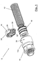
- connection arrangement 10 is intended for connection to a corrugated pipe 12 and for this purpose comprises a base body 14, a latching unit 16 and a sealing element 18
- Figure 1 shows an exploded view of the various components Figure 2 this represents in the connected state.
- the base body 14 has a receiving recess 14a (see also Figure 5 ), which serves to accommodate the corrugated tube 12 inserted in the direction of insertion E ( Figure 2 ), so that in the connected state according to Figure 2 a central passage 14b of the base body 14 is connected to a central passage 12a of the corrugated pipe 12.
- the fluid-tight formation of this connection is ensured by the sealing element 18, which is arranged between the inner circumferential surface of the receiving recess 14a of the base body 14 and the outer circumferential surface of the corrugated pipe 12.
- the latching unit 16 is also inserted into a circumferential opening 14c of the base body 14 and secures the corrugated pipe 12 in the receiving recess 14a.
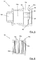
- the latching unit 16 comprises a latching element carrier 20 designed as a slotted ring, along the circumference of which a plurality of latching elements 22 designed as latching hooks are arranged (see also FIG Figure 4 ).
- the free ends 22a of the latching elements 22 engage in the connected state according to FIG Figure 2 into a corrugated trough 12b of the corrugated pipe 12 and resist, like a barbs, a pulling out of the corrugated pipe 12 from the receiving recess 14a.
- the extension of the locking element carrier 20 is shown in FIG Figure 2 indicated by dotted lines. It can be seen that the latching element carrier 20 does not need to be a solid component. Rather, it is only formed by a thin material web of the latching unit 16, which extends over 360 ° up to the slot 20a (see also Figures 3 and 4 ).
- the latching element carrier 20 is integrally connected to a base element 24 of the latching unit 16, which is mechanically robust and thus enables the latching unit 16 to be handled without the risk of damaging the latching elements 22.
- the base element 24 is U-shaped and comprises a base leg 24a and two side legs 24b. In the illustrated embodiment, both the base leg 24a and the two side legs 24b are directly connected in one piece to the latching element carrier 20, i.e. not only via the "detour" via another part, for example one of the other legs of the U-shape.
- a securing projection 26 is formed on each of the two side legs 24b, which, when the locking unit 16 is inserted into the circumferential opening 14c of the base body 14, engages in a securing opening 28 of the base body and thus prevents the locking unit 16 from accidentally falling out of the corrugated pipe 12 when the corrugated pipe 12 has not yet been inserted Base body 14 secures.
- the surfaces 42 of the two side legs 24b serve as guide surfaces, which when the latching unit 16 is inserted into the circumferential opening 14c in the direction of insertion indicated by the arrow R with associated mating guide surfaces 44 of the base body 14 (see FIG Figure 5 ) work together.
- contact surfaces 30 and 32 are formed on the base element 24, which interact with associated counter-contact surfaces 34 and 36 of the base body 14, in order to be able to transfer forces introduced into the base body 14 from the corrugated pipe 12 via the locking elements 22 into the locking unit 16. Since the base element 24, due to its U-shape, does not extend over the entire circumference of the corrugated tube 12, contact elements 38 are provided on the side of the locking element carrier 20 on its side facing away from the locking elements 22, the free ends 38a of which for force transmission with a mating contact surface 40 of the base body 14 cooperate.
- the base body 14 has an orientation aid projection 46 which, when the base body 14 and latching unit 16 are connected, engages in an orientation aid recess 48 of the latching unit 16.
- the interaction of the orientation aid projection 46 with the orientation aid recess 48 ensures that the locking unit 16 is inserted in the correct orientation, ie with locking elements 22 pointing in the insertion direction E, into the circumferential opening 14c of the base body 14. If one were to attempt to insert the latching unit 16 into the circumferential opening 14c with latching elements 22 pointing against the insertion direction E, the latching elements 22 would collide with the orientation aid projection 46, which would prevent the latching unit 16 from being inserted into the base body 14.
- the interaction of the orientation aid projection 46 with the orientation aid recess 48 provides protection against rotation for the latching unit 16.
- the orientation aid projection 46 has an inclined surface 46a and is arranged at a distance from the base leg 24a of the base element 24 of the latching unit 16.
- a loosening tool for example the tip of a flat-slotted screwdriver, can be inserted into the gap formed in this way by the orientation aid recess 48. If you swivel the release tool in Figure 2 clockwise and uses the orientation aid projection 46 as an abutment, the latching unit 16 is levered somewhat out of the base body 14, releasing the latching of the securing projections 26 with the securing recesses 28. The locking unit 16 can then be grasped on the base element 24 and completely detached from the base body. In this way, the orientation aid recess 48 also forms a release aid recess at the same time. In principle, however, it is also conceivable to provide the orientation aid recess and the release aid recess as recesses formed independently of one another.
- the sealing element 18 is arranged in the insertion direction E behind the latching unit 16. How better in Figure 6 As can be seen, the sealing element 18 is essentially tubular. In the illustrated embodiment, sealing lips 18b and 18c are provided both on the outside and on the inside of the pipe section 18a. The inner sealing lips 18b can be positioned such that at least one of them can be brought into sealing engagement with the summit section of a wave crest 12c of the corrugated pipe 12. Furthermore, in the illustrated embodiment, a collar 18d pointing radially inward is provided at the end of the pipe section 18a remote from the latching unit 16. This can form an additional face seal for the end of the corrugated pipe 12.
- this radially inner collar 18d can also be dispensed with.
- a radially outward direction pointing collar 18e may be provided at the end of the tube section 18a adjacent to the latching unit 16. This collar 18e prevents the sealing element 18 from being undesirably displaced by the corrugated pipe 12 when it is inserted.
- connection arrangement 10 that is prepared for the insertion of a corrugated pipe 12
- the sealing element 18 is first arranged in the receiving recess 14a until it rests against the bottom 14a1 thereof.
- the latching unit 16 is then inserted into the circumferential opening 14c until the securing projections 26 engage in the securing recesses 28.
- the end 12d of the corrugated pipe 12 runs against the locking elements 22 and pushes the contact surface 30 of the locking unit 16 into contact with the counter contact surface 34 of the base body 14.
- the resistance is generated that is required so that when the corrugated pipe 12 is further inserted into the connecting arrangement 10, the locking elements 22 can be elastically deflected to such an extent that the corrugated peaks 12c of the corrugated pipe 12 can move past the free ends of the locking elements 22.
- the elastic deflection movement must be applied solely by elastic deformation of the latching elements 22, while it is in the circumferential sections adjacent to the slot 20a of the latching element carrier 20 can be composed of an elastic deformation of the locking element carrier 20 on the one hand and an elastic deformation of the locking elements 22 on the other hand.
- the latching elements 22 are therefore less stressed in these circumferential sections. If the corrugated pipe 12 has been pushed completely into the connecting arrangement 10, the free ends of the latching elements 22 pivot back under the effect of their own elasticity and engage in a corrugated trough 12b of the corrugated pipe 12.
- the latching elements 22 are acted upon in such a way that they engage even more strongly in the corrugated trough 12b of the corrugated pipe 12.
- the contact surface 32 of the latching unit 16 engages with the associated counter-contact surface 36 of the base body 14. In this way, a non-destructive detachment of the corrugated pipe 12 from the connection arrangement 10 is prevented.
- the locking unit 16 is levered out of the peripheral opening 14c of the base body with the aid of a release tool so far that the locking unit 16 can be grasped by its base element 24 and completely pulled out of the peripheral opening 14c.
- the sections of the latching element carrier 22 adjacent to the slot 20a are widened against their inherent elasticity, so that they can move past the corrugated pipe 22.
- the latching elements 22 are arranged along the circumference of the latching element carrier 20 in an essentially gapless sequence, ie essentially without any spacing from one another.
- This has the advantage that the locking elements 22 form a baffle wall for water that is ejected, for example, by a high-pressure cleaning device and hits the connecting arrangement 10 with force.
- the locking elements 22 - with the exception of the locking elements 22 ′ immediately adjacent to the slot 20a - can be connected to one another by means of plastic skins 50 in the freshly manufactured state.
- plastic skins 50 together with the surfaces of the latching elements 22 form an annular surface that is continuous except for the slot 20a.
- the separation points of the latching elements 22 can only be recognized by means of small notches 52.
- the latching elements 22 When the latching elements 22 are expanded as a result of the insertion of the corrugated tube 12, not all of the skins 50 necessarily have to tear. In particular in the slot 20a, the latching elements 22 need to expand less strongly when the corrugated pipe 12 is inserted, since the latching element carrier 20 also elastically evades the inserted corrugated pipe 12 here.
- the connections formed by the non-torn plastic skins 50 between adjacent latching elements 22 improve the impact wall effect, which makes it difficult for water to penetrate.
- FIG. 7 The illustrated embodiment of the base body 114 differs from that, for example, in FIG Figures 1 and 5 illustrated embodiment of the base body 14 in particular by the guide surface 154. Therefore, in Figure 7 Similar parts are provided with the same reference numerals as in FIGS Figures 1 and 5 , but increased by the number 100.
- the base body 114 according to Figure 7 will therefore only be described in the following to the extent that it differs from the embodiment according to FIG Figures 1 and 5 differs, otherwise expressly referring to the description of the embodiment in accordance with Figures 1 and 5 referenced.
- Figure 7 has a guide surface 154 which is essentially V-shaped and tapers from a circumferential opening 114c to a securing recess 128.
- the guide surface 154 has a depth that decreases from the opening of the V-shape to the tip of the V-shape.
- the cross section of the V-shaped guide surface 154 is based on that according to the exemplary embodiment Figures 3 and 4 shown hemispherical shape of the securing elements 26 adapted.
- the Base body 114 also has two securing recesses 126 and two associated guide surfaces 154.
Landscapes
- Engineering & Computer Science (AREA)
- General Engineering & Computer Science (AREA)
- Mechanical Engineering (AREA)
- Quick-Acting Or Multi-Walled Pipe Joints (AREA)
- Joints That Cut Off Fluids, And Hose Joints (AREA)
- Infusion, Injection, And Reservoir Apparatuses (AREA)
- Diaphragms And Bellows (AREA)
Description
- Die Erfindung betrifft eine Verbindungsanordnung.
- Derartige Verbindungsanordnungen sind beispielsweise aus der
WO 1998/ 040 656 A1 bekannt. Gemäß einer ersten in dieser Schrift offenbarten Ausführungsvariante umfasst die Verbindungsanordnung zwei Rasteinheiten, deren Rastelementträger jeweils kreisbogenförmig ausgebildet und an dem Grundkörper schwenkbar angelenkt sind. Dieses Konzept bedingt einen komplizierten und beschädigungsanfälligen Aufbau sowohl des Grundkörpers als auch der Rasteinheiten. Bei einer zweiten Ausführungsvariante weist die Rasteinheit einen U-förmig ausgebildeten Rastelementträger auf, wobei die Rastelemente nur an dem Basisschenkel der U-Form vorgesehen sind. Diese Ausführungsvariante vermag daher keine zuverlässige Verbindung zwischen dem Grundkörper und dem Wellrohr sicherzustellen. - Ferner sei an diese Stelle auf die Dokumente
EP 1 845 299 A1 ,JP 2014 052023 A US 5 527 072 A undEP 0 330 250 A1 hingewiesen. Demgegenüber ist es Aufgabe der Erfindung, eine Verbindungsanordnung der gattungsgemäßen Art bereitzustellen, welche einerseits einfach aufgebaut ist, andererseits aber auch eine zuverlässige Verbindung von Grundkörper und Wellrohr, beispielsweise hinsichtlich der Dichtheit der Verbindung, gewährleistet. - Diese Aufgabe wird erfindungsgemäß durch eine Verbindungsanordnung nach Anspruch 1 gelöst. Auf diese Weise ist zum einen sichergestellt, dass das Wellrohr allseitig von der Rasteinheit gehalten wird. Zum anderen ist hierfür lediglich eine einzige Rasteinheit erforderlich.
- In Weiterbildung der Erfindung wird vorgeschlagen, dass die Rastelemente längs des Umfangs des als Schlitzring ausgebildeten Rastelementträgers in im Wesentlichen lückenloser Folge angeordnet sind. Diese Ausgestaltung ist beispielsweise für den Fall vorteilhaft, dass die Maschine bzw. Anlage, an der die erfindungsgemäße Verbindungsanordnung verbaut ist, mit einem Hochdruckreinigungsgerät gereinigt werden soll. In diesem Fall können die über den gesamten Umfang des Schlitzrings im Wesentlichen lückenlos nebeneinander angeordneten Rastelemente eine Prallwand bilden, die die Wucht des auftreffenden Wassers von den in Einführrichtung dahinter angeordneten Dichtungsmitteln der Verbindungsanordnung fern hält. Diese Dichtungsmittel brauchen daher nur noch gegen im Wesentlichen drucklos anstehendes Wasser abzudichten. In diesem Zusammenhang ist auf die Normengruppe IP x9K, insbesondere die Norm IP 69K, zu verweisen, die Prüfkriterien für die Reinigung mittels eines Hochdruckreinigungsgeräts unter verschiedenen vorbestimmten Winkeln enthalten.
- Die Funktion der Prallwand können die Rastelemente noch besser erfüllen, wenn mit Ausnahme der beidseits des Schlitzes angeordneten Rastelemente einander benachbarte Rastelemente mittels eines Häutchens miteinander verbunden sind. Vorzugsweise ist dieses Häutchen aus dem gleichen Material gebildet wie die Rastelemente, beispielsweise Kunststoff. Zwar sind die Häutchen so dünn auszulegen, dass sie beim Aufweiten der Rastelemente infolge des Einführens des Wellrohrs reißen können. Jedoch brauchen nicht notwendigerweise alle Häutchen zu reißen. Insbesondere in den dem Schlitz des Schlitzrings benachbarten Abschnitten brauchen sich die Rastelemente beim Einführen des Wellrohrs weniger stark aufzuweiten, da hier auch der Rastelementträger dem eingeführten Wellrohr elastisch ausweichen kann. Die von den nicht gerissenen Häutchen gebildeten Verbindungen zwischen einander benachbarten Rastelementen bilden eine weitere Dichtung, die das Eindringen von Wasser erschwert. Vorteilhafterweise sind die Häutchen weniger als 0,1 mm, vorzugsweise weniger als 0,05 mm, dick.
- Um verhindern zu können, dass sich die Rasteinheit selbsttätig vom Grundkörper löst, wird vorgeschlagen, dass die Rasteinheit wenigstens ein Sicherungselement umfasst, welches mit einem zugeordneten Gegensicherungselement des Grundkörpers in einen die Rasteinheit am Grundkörper sichernden Sicherungseingriff bringbar ist. Vorteilhafterweise kann dieses wenigstens eine Sicherungselement als Sicherungsvorsprung ausgebildet sein, während das Gegensicherungselement als Sicherungsausnehmung, vorzugsweise als eine, die Umfangswand des Grundkörpers durchsetzende Sicherungsdurchbrechung, ausgebildet sein kann. Dabei hat insbesondere die Ausführung der Sicherungsausnehmung als Sicherungsdurchbrechung den Vorteil, dass die Herstellung des Sicherungseingriffs visuell überprüft werden kann. Hierfür ist es ferner vorteilhaft, wenn das Material der Rasteinheit und das Material des Grundkörpers zueinander einen farblichen Kontrast aufweisen.
- Wie sich aus der vorstehenden Diskussion der Rasteinheit ergibt, hat diese verschiedene Funktionen zu erfüllen, neben dem sicheren Halt des Wellrohrs beispielsweise auch die Sicherstellung ihres eigenen Halts am Grundkörper. Um alle diese Funktionen zuverlässig erfüllen zu können, ist es erfindungsgemäß, dass die Rasteinheit ein Basiselement umfasst, das mit Rastelementträger einstückig verbunden ist.
- Beispielsweise kann das wenigstens eine Sicherungselement an dem Basiselement ausgebildet sein.
- Zusätzlich oder alternativ kann das Basiselement wenigstens eine Führungsfläche aufweisen und kann der Grundkörper wenigstens eine Gegenführungsfläche aufweisen, welche zu Beginn des Einsetzens der Rasteinheit in den Grundkörper miteinander in Führungseingriff bringbar sind und im Zuge des weiteren Einsetzens der Rasteinheit in den Grundkörper aneinander abgleiten.
- In einer Weiterbildung der Erfindung kann an dem Grundkörper wenigstens eine Führungsfläche ausgebildet sein, welche z.B. aus dem Grundkörper ausgenommen ist und mit dem wenigstens einen Sicherungselement zusammenwirkt. Dabei kann die Führungsfläche für das Sicherungselement beispielsweise im Wesentlichen V-förmig ausgebildet sein, wobei an der Spitze der V-Form die entsprechende Sicherungsausnehmung angeordnet sein kann und wobei sich die V-Form bis zu der Umfangsöffnung in dem Grundkörper hin öffnen kann. Ferner kann die V-förmige Führungsfläche eine zur Spitze der V-Form hin abnehmende Tiefe aufweisen. Der Querschnitt der Führungsfläche kann vorteilhafterweise an eine mit der Führungsfläche in Eingriff tretende Fläche des entsprechenden Sicherungselements angepasst sein.
- Beim Einführen der Rasteinheit in den Grundkörper kann das wenigstens eine Sicherungselement mit der wenigstens einen ihm zugehörigen Führungsfläche, vorteilhafterweise an der breitesten und tiefsten Stelle der V-Form, in Eingriff treten und kann somit während des weiteren Einführens der Rasteinheit zu der dem Sicherungselement zugehörigen Sicherungsausnehmung geführt werden.
- Erfindungsgemäß weist das Basiselement wenigstens eine in Einführrichtung gerichtete Anlagefläche oder/und wenigstens eine entgegen der Einführrichtung gerichtete Anlagefläche auf, welche jeweils mit einer zugeordneten Gegenanlagefläche des Grundkörpers in Kraftübertragungseingriff bringbar sind. Dabei kann das Zusammenwirken der wenigstens einen in Einführrichtung weisenden Anlagefläche mit der jeweils zugehörigen Gegenanlagefläche den Widerstand bieten, der erforderlich ist, um beim Einführen des Wellrohrs in die Verbindungsanordnung die Rastelemente der in den Grundkörper eingesetzten Rasteinheit so weit elastisch auslenken zu können, dass sich die Wellenberge des Wellrohrs an den freien Enden der Rastelemente vorbeibewegen können. Wurde das Wellrohr vollständig in die Verbindungsanordnung eingeschoben, so schwenken die freien Enden der Rastelemente unter der Wirkung ihrer Eigenelastizität zurück und greifen in ein Wellental des Wellrohrs ein. Versucht man nun, das Wellrohr wieder aus der Verbindungsanordnung herauszuziehen, so werden die Rastelemente derart beaufschlagt, dass sie noch stärker in das Wellental des Wellrohrs eingreifen. Gleichzeitig tritt die wenigstens eine entgegen der Einführrichtung gerichtete Anlagefläche der Rasteinheit mit der jeweils zugehörigen Gegenanlagefläche des Grundkörpers in Kraftübertragungseingriff. Auf diese Weise wird ein zerstörungsfreies Lösen des Wellrohrs aus der Verbindungsanordnung verhindert. Nachzutragen ist noch, dass sich die Richtungsangabe "eine Fläche weist in eine bestimmte Richtung" auf die Richtung der Flächennormalen dieser Fläche bezieht, die sich in den an diese Fläche angrenzenden freien Raum erstreckt.
- Um die vorstehend erläuterten Funktionen zuverlässig erfüllen zu können, ist es vorteilhaft, wenn das Basiselement U-förmig ausgebildet ist.
- Um das Basiselement mechanisch robust und widerstandsfähig mit dem Rastelementträger verbinden zu können, wird vorgeschlagen, dass der Basisschenkel und vorzugsweise wenigstens einer der Seitenschenkel, noch bevorzugter beide Seitenschenkel, der U-Form unmittelbar mit dem Rastelementträger einstückig verbunden sind. Dies ist insbesondere im Hinblick auf die Weiterleitung der vom Wellrohr ausgehenden Kräfte von den Rastelementen über den Rastelementträger und weiter über das Basiselement in den Grundkörper vorteilhaft.
- Wie vorstehend bereits angedeutet wurde, kann das wenigstens eine Sicherungselement an dem Basiselement angeordnet sein. Vorzugsweise kann es an einem der Seitenschenkel der U-Form angeordnet sein.
- Um trotz der Tatsache, dass das Basiselement lediglich U-förmig ausgebildet ist und somit zumindest in den dem Schlitz benachbarten Abschnitten des Rastelementträgers die vom Wellrohr ausgehenden Kräfte nicht unmittelbar an den Grundkörper weiterleiten kann, auch in diesem Bereich eine zuverlässige Kraftweiterleitung bereitstellen zu können, ist es erfindungsgemäß, dass in den dem Schlitz benachbarten Abschnitten des Rastelementträgers auf der von den Rastelementen abgewandten Seite des Rastelementträgers eine Mehrzahl von entgegen der Einführrichtung weisenden Anlageelementen vorgesehen ist, welche mit einer zugeordneten Gegenanlagefläche des Grundkörpers in Kraftübertragungseingriff bringbar sind. Diese Anlageelemente übernehmen in dem Winkelbereich, über den sich das Basiselement nicht erstreckt, die Funktion der entgegen der Einführrichtung gerichteten Anlagefläche des Basiselements. Insgesamt ergibt sich somit ein über den Umfang des Rohrs gleichmäßiger Kraftschluss der Verbindung.
- Um sicherstellen zu können, dass die Rasteinheit in der richtigen Orientierung in den Grundkörper eingesetzt wird, in der die Rastelemente auf das in die Verbindungsanordnung eingeführte Wellrohr eine Widerhakenwirkung ausüben können, wird vorgeschlagen, dass am Grundkörper ein Orientierungshilfevorsprung vorgesehen ist, der in die Umfangsöffnung hineinragt, während an der Rasteinheit, vorzugsweise am Basiselement der Rasteinheit, eine zugehörige Orientierungshilfeausnehmung ausgebildet ist. Durch das Zusammenwirken des Orientierungshilfevorsprungs mit der Orientierungshilfeausnehmung kann zusätzlich zu dem durch das wenigstens eine Sicherungselement bereitgestellten Verdrehschutz ein weiterer Schutz gegen unerwünschtes Verdrehen der Rasteinheit bereitgestellt werden.
- Wie sich aus der vorstehenden Erläuterung ergibt, ist es erforderlich, zuerst die Rasteinheit vom Grundkörper zu lösen, wenn man das Wellrohr wieder von der Verbindungsanordnung entfernen möchte. Um ein unbeabsichtigtes Lösen verhindern zu können, ist die Rasteinheit jedoch vorzugsweise derart in die Umfangsöffnung eingesetzt, dass kein Abschnitt der Rasteinheit über den Rand der Umfangsöffnung hinausragt. Um gleichwohl ein Lösen der Rasteinheit vom Grundkörper ermöglichen zu können, wird vorgeschlagen, dass an der Rasteinheit, vorzugsweise am Basiselement der Rasteinheit, eine Lösehilfeausnehmung vorgesehen ist. In diese Lösehilfeausnehmung kann ein Lösewerkzeug eingeführt werden, beispielsweise die Spitze eines Schraubendrehers, insbesondere eines Schraubendrehers für Flachschlitzschrauben. Vorteilhafterweise ist die Lösehilfeausnehmung dem Rand der Umfangsöffnung benachbart angeordnet, um den Grundkörper als Widerlager zum Heraushebeln der Rasteinheit mittels des Lösewerkzeugs verwenden zu können. Beim Herausziehen der Rasteinheit aus dem Grundkörper werden die dem Schlitz des Schlitzring benachbarten Abschnitte des Rastelementträgers entgegen ihrer Eigenelastizität aufgeweitet, so dass sie sich am Wellrohr vorbeibewegen können.
- Nachzutragen ist noch, dass die Verbindungsanordnung ferner ein Dichtungselement aufweisen kann, welches die Außenumfangsfläche des Wellrohrs zur Innenumfangsfläche des Grundkörpers hin abdichtet. Das Dichtungselement kann daher vorteilhafterweise zwischen der Außenumfangsfläche des Wellrohrs und der Innenumfangsfläche des Grundkörpers angeordnet sein. Vorteilhafterweise ist der Rohrabschnitt in Einführrichtung des Wellrohrs gesehen hinter der Rasteinheit angeordnet.
- Das Dichtungselement kann beispielsweise einen Rohrabschnitt umfassen. An der Außenseite oder/und der Innenseite des Rohrabschnitts können Dichtlippen vorgesehen sein. Die inneren Dichtlippen können dabei derart positioniert sein, dass wenigstens eine von ihnen mit dem Gipfelabschnitt eines Wellenbergs des Wellrohrs in Dichtungseingriff bringbar ist. Darüber hinaus können die inneren Dichtlippen so angeordnet sein, dass auch bei Wellrohren mit unterschiedlicher Profilteilung (grob und fein) und somit unterschiedlichen Abständen aufeinander folgender Wellenberge mindestens eine Dichtlippe in Dichteingriff mit einem Wellenberg steht.
- In diesem Zusammenhang ist darauf hinzuweisen, dass die inneren Dichtlippen und die äußeren Dichtlippen zueinander versetzt angeordnet sein können. Dies bietet den Vorteil, eine Pressung und damit eine zu hohe Spannung im Material verhindern zu können. Hohe Spannungen bergen nämlich die Gefahr, ein Kriechen des Materials hervorzurufen, das im Laufe der Zeit Undichtigkeiten des Dichtungselements nach sich ziehen kann.
- Ferner kann an dem von der Rasteinheit entfernten Ende des Rohrabschnitts ein nach radial innen weisender Kragen vorgesehen sein. Dieser kann als zusätzliche stirnseitige Dichtung für das Ende des Wellrohrs dienen. Aus herstellungstechnischen Gründen kann auf diesen radial inneren Kragen auch verzichtet werden. Schließlich kann an dem der Rasteinheit benachbarten Ende des Rohrabschnitts ein nach radial außen weisender Kragen vorgesehen sein. Dieser Kragen kann dafür Sorge tragen, dass das Dichtungselement beim Einführen des Wellrohrs an Ort und Stelle gehalten und nicht vom Wellrohr unerwünschterweise verschoben wird. Zudem stellt dieser Kragen eine zusätzliche Barriere gegenüber unter Druck anstehendem Wasser dar.
- Nachzutragen ist noch, dass das Dichtungselement aus einem gummielastischen Material gefertigt sein, beispielsweise TPE ( T hermo p lastischem E lastomer) oder EPDM ( E thylen- P ropylen- D ien- K autschuk).
- Nachzutragen ist ferner, dass die erfindungsgemäße Rasteinheit und/oder der Grundkörper aus Kunststoff gefertigt sein kann bzw. können, beispielsweise PA ( P oly a mid), insbesondere PA6 und/oder PA12, oder PP ( P oly p ropylen) oder PVDF ( P oly v inyli d enf l uorid). Darüber hinaus können sie als Spritzgussteil gefertigt sein, wobei insbesondere der Grundkörper vorzugsweise unter Verwendung einer lediglich zwei Formhälften umfassenden Spritzgussform hergestellt werden kann.
- Die Erfindung wird im Folgenden anhand der beigefügten Zeichnung an einem Ausführungsbeispiel näher erläutert werden. Es stellt dar:
- Figur 1
- eine perspektivische Explosionsdarstellung einer erfindungsgemäßen Verbindungsanordnung mit zugehörigem Wellrohr;
- Figur 2
- eine geschnittene Seitenansicht der Verbindungsanordnung gemäß
Figur 1 mit eingeführtem Wellrohr; - Figur 3
- eine in Einführrichtung gesehene Ansicht der Rasteinheit;
- Figur 4
- eine entgegen der Einführrichtung gesehene Ansicht der Rasteinheit;
- Figur 5
- eine geschnittene Seitenansicht des Grundkörpers der Verbindungsanordnung gemäß
Figur 1 ; - Figur 6
- eine geschnittene Seitenansicht des Dichtungselements der Verbindungsanordnung gemäß
Figur 1 ; und - Figur 7
- eine geschnittene Seitenansicht einer weiteren Ausführungsform des Grundkörpers der Verbindungsanordnung.
- In den
Figuren 1 und2 ist eine erfindungsgemäße Verbindungsanordnung ganz allgemein mit 10 bezeichnet. Die Verbindungsanordnung 10 ist zur Verbindung mit einem Wellrohr 12 bestimmt und umfasst hierzu einen Grundkörper 14, eine Rasteinheit 16 und ein Dichtungselement 18. WährendFigur 1 eine Explosionsdarstellung der verschiedenen Komponenten zeigt, stelltFigur 2 diese im verbundenen Zustand dar. - Der Grundkörper 14 weist eine Aufnahmevertiefung 14a auf (siehe auch
Figur 5 ), welche zur Aufnahme des in Einführrichtung E eingeführten Wellrohrs 12 dient (Figur 2 ), so dass im verbundenen Zustand gemäßFigur 2 ein zentraler Durchgang 14b des Grundkörpers 14 mit einem zentralen Durchgang 12a des Wellrohrs 12 in Verbindung steht. Die fluiddichte Ausbildung dieser Verbindung wird durch das Dichtungselement 18 sichergestellt, das zwischen der Innenumfangsfläche der Aufnahmevertiefung 14a des Grundkörpers 14 und der Außenumfangsfläche des Wellrohrs 12 angeordnet ist. - Im verbundenen Zustand gemäß
Figur 2 ist ferner die Rasteinheit 16 in eine Umfangsöffnung 14c des Grundkörpers 14 eingesetzt und sichert das Wellrohr 12 in der Aufnahmevertiefung 14a. Die Rasteinheit 16 umfasst hierzu einen als Schlitzring ausgebildeten Rastelementträger 20, längs dessen Umfang eine Mehrzahl von als Rasthäkchen ausgebildeten Rastelementen 22 angeordnet ist (siehe auchFigur 4 ). Die freien Enden 22a der Rastelemente 22 greifen in dem verbundenen Zustand gemäßFigur 2 in ein Wellental 12b des Wellrohrs 12 ein und widersetzen sich Widerhaken-artig einem Herausziehen des Wellrohrs 12 aus der Aufnahmevertiefung 14a. - Die Erstreckung des Rastelementträgers 20 ist in
Figur 2 gepunktet angedeutet. Man erkennt, dass der Rastelementträger 20 kein massives Bauteil zu sein braucht. Vielmehr wird er lediglich von einem dünnen Materialsteg der Rasteinheit 16 gebildet, der sich bis auf den Schlitz 20a über 360° erstreckt (siehe auchFiguren 3 und 4 ). - Der Rastelementträger 20 ist mit einem Basiselement 24 der Rasteinheit 16 einstückig verbunden, das mechanisch robust ausgebildet ist und somit die Handhabung der Rasteinheit 16 ermöglicht, ohne Risiko einer Beschädigung der Rastelemente 22. Das Basiselement 24 ist U-förmig ausgebildet und umfasst einen Basisschenkel 24a und zwei Seitenschenkel 24b. In dem dargestellten Ausführungsbeispiel sind sowohl der Basisschenkel 24a als auch die beiden Seitenschenkel 24b mit dem Rastelementträger 20 unmittelbar einstückig verbunden, d.h. nicht nur über den "Umweg" über ein anderes Teil, beispielsweise einen der anderen Schenkel der U-Form.
- An den beiden Seitenschenkeln 24b ist jeweils ein Sicherungsvorsprung 26 ausgebildet, der in dem in die Umfangsöffnung 14c des Grundkörpers 14 eingesetzten Zustand der Rasteinheit 16 in eine Sicherungsdurchbrechung 28 des Grundkörpers eingreift und so die Rasteinheit 16 bei noch nicht eingeführtem Wellrohr 12 gegen unbeabsichtigtes Herausfallen aus dem Grundkörper 14 sichert.
- Ferner dienen die Oberflächen 42 der beiden Seitenschenkel 24b als Führungsflächen, welche beim Einsetzen der Rasteinheit 16 in die Umfangsöffnung 14c in der durch den Pfeil R angedeuteten Einsetzrichtung mit zugeordneten Gegenführungsflächen 44 des Grundkörpers 14 (siehe
Figur 5 ) zusammenwirken. - Ferner sind an dem Basiselement 24 Anlageflächen 30 und 32 ausgebildet, die mit zugehörigen Gegenanlageflächen 34 bzw. 36 des Grundkörpers 14 zusammenwirken, um von dem Wellrohr 12 über die Rastelemente 22 in die Rasteinheit 16 eingeleitete Kräfte an den Grundkörper 14 weiterleiten zu können. Da sich das Basiselement 24 aufgrund seiner U-Form nicht über den gesamten Umfang des Wellrohrs 12, erstreckt, sind an dem Rastelementträger 20 auf dessen von den Rastelementen 22 abgewandter Seite Anlageelemente 38 vorgesehen, deren freie Enden 38a zur Kraftweiterleitung mit einer Gegenanlagefläche 40 des Grundkörpers 14 zusammenwirken.
- Wie am besten in
Figur 2 zu erkennen ist, verfügt der Grundkörper 14 über einen Orientierungshilfevorsprung 46, der im verbundenen Zustand von Grundkörper 14 und Rasteinheit 16 in eine Orientierungshilfeausnehmung 48 der Rasteinheit 16 eingreift. Durch das Zusammenwirken des Orientierungshilfevorsprungs 46 mit der Orientierungshilfeausnehmung 48 kann sichergestellt werden, dass die Rasteinheit 16 in der richtigen Orientierung, d.h. mit in Einführrichtung E weisenden Rastelementen 22, in die Umfangsöffnung 14c des Grundkörpers 14 eingesetzt wird. Würde man versuchen, die Rasteinheit 16 mit entgegen der Einführrichtung E weisenden Rastelementen 22 in die Umfangsöffnung 14c einzusetzen, so würden die Rastelemente 22 mit dem Orientierungshilfevorsprung 46 kollidieren, wodurch das Einsetzen der Rasteinheit 16 in den Grundkörper 14 verhindert werden würde. Außerdem stellt das Zusammenwirken des Orientierungshilfevorsprungs 46, mit der Orientierungshilfeausnehmung 48 einen Verdrehschutz für die Rasteinheit 16 dar. - Wie in
Figur 2 ferner dargestellt ist, weist der Orientierungshilfevorsprung 46 eine geneigte Oberfläche 46a auf und ist von dem Basisschenkel 24a des Basiselements 24 der Rasteinheit 16 mit Abstand angeordnet. In den auf diese Weise von der Orientierungshilfeausnehmung 48 gebildeten Spalt kann ein Lösewerkzeug, beispielsweise die Spitze eines Flachschlitz-Schraubendrehers, eingeführt werden. Schwenkt man das Lösewerkzeug inFigur 2 im Uhrzeigersinn und verwendet den Orientierungshilfevorsprung 46 als Widerlager, so wird die Rasteinheit 16 unter Aufheben der Verrastung der Sicherungsvorsprünge 26 mit den Sicherungsausnehmungen 28 etwas aus dem Grundkörper 14 herausgehebelt. Anschließend kann man die Rasteinheit 16 am Basiselement 24 ergreifen und vollständig vom Grundkörper lösen. Auf diese Weise bildet die Orientierungshilfeausnehmung 48 gleichzeitig auch eine Lösehilfeausnehmung. Grundsätzlich ist es jedoch auch denkbar, die Orientierungshilfeausnehmung und die Lösehilfeausnehmung als voneinander unabhängig ausgebildete Ausnehmungen vorzusehen. - Wie in
Figur 2 dargestellt ist, ist das Dichtungselement 18 in Einführrichtung E hinter der Rasteinheit 16 angeordnet. Wie besser inFigur 6 zu erkennen ist, ist das Dichtungselement 18 im Wesentlichen rohrförmig ausgebildet. In dem dargestellten Ausführungsbeispiel sind sowohl an der Außenseite als auch an der Innenseite des Rohrabschnitts 18a Dichtlippen 18b bzw. 18c vorgesehen. Die inneren Dichtlippen 18b können dabei derart positioniert sein, dass wenigstens eine von ihnen mit dem Gipfelabschnitt eines Wellenbergs 12c des Wellrohrs 12 in Dichtungseingriff bringbar ist. Ferner ist in dem dargestellten Ausführungsbeispiel an dem von der Rasteinheit 16 entfernten Ende des Rohrabschnitts 18a ein nach radial innen weisender Kragen 18d vorgesehen. Dieser kann eine zusätzliche stirnseitige Dichtung für das Ende des Wellrohrs 12 bilden. Zur Vereinfachung der Herstellung des Dichtungselements 18 kann aber auf diesen radial inneren Kragen 18d auch verzichtet werden. Schließlich ist an dem der Rasteinheit 16 benachbarten Ende des Rohrabschnitts 18a ein nach radial außen weisender Kragen 18e vorgesehen sein. Dieser Kragen 18e verhindert, dass das Dichtungselement 18 beim Einführen des Wellrohrs 12 von diesem unerwünschterweise verschoben wird. - Zur Herstellung eines für das Einführen eines Wellrohrs 12 vorbereiteten Zustands der Verbindungsanordnung 10 ordnet man zunächst das Dichtungselement 18 in der Aufnahmevertiefung 14a an, bis es an deren Boden 14a1 anliegt. Anschließend führt man die Rasteinheit 16 in die Umfangsöffnung 14c ein, bis die Sicherungsvorsprünge 26 in die Sicherungsausnehmungen 28 einrasten.
- Führt man nun das Wellrohr 12 in die Verbindungsanordnung 10 ein, so läuft das Ende 12d des Wellrohrs 12 gegen die Rastelemente 22 an und schiebt die Anlagefläche 30 der Rasteinheit 16 in Anlage gegen die Gegenanlagefläche 34 des Grundkörpers 14. Durch das Zusammenwirken der Flächen 30, 34 wird der Widerstand erzeugt, der erforderlich ist, damit sich beim weiteren Einführen des Wellrohrs 12 in die Verbindungsanordnung 10 die Rastelemente 22 so weit elastisch auslenken lassen, dass sich die Wellenberge 12c des Wellrohrs 12 an den freien Enden der Rastelemente 22 vorbeibewegen können. Dabei muss in einem Umfangsabschnitt, in dem der Rastelementträger 20 einstückig mit dem Basiselement 24 der Rasteinheit 16 verbunden ist, die elastische Auslenkbewegung alleine durch eine elastische Verformung der Rastelemente 22 aufgebracht werden, während sie sich in den an den Schlitz 20a des Rastelementträgers 20 benachbarten Umfangsabschnitten aus einer elastischen Verformung des Rastelementträgers 20 einerseits und einer elastischen Verformung der Rastelemente 22 andererseits zusammensetzen kann. In diesen Umfangsabschnitten werden die Rastelemente 22 daher weniger stark beansprucht. Wurde das Wellrohr 12 vollständig in die Verbindungsanordnung 10 eingeschoben, so schwenken die freien Enden der Rastelemente 22 unter der Wirkung ihrer Eigenelastizität zurück und greifen in ein Wellental 12b des Wellrohrs 12 ein.
- Versucht man nun, das Wellrohr 12 wieder aus der Verbindungsanordnung 10 herauszuziehen, so werden die Rastelemente 22 derart beaufschlagt, dass sie noch stärker in das Wellental 12b des Wellrohrs 12 eingreifen. Gleichzeitig tritt die Anlagefläche 32 der Rasteinheit 16 mit der zugeordneten Gegenanlagefläche 36 des Grundkörpers 14 in Eingriff. Auf diese Weise wird ein zerstörungsfreies Lösen des Wellrohrs 12 aus der Verbindungsanordnung 10 verhindert.
- Wenn man das Wellrohr 12 wieder aus der Verbindungsanordnung 10 herausnehmen möchte, ist es erforderlich, zuerst die Rasteinheit 16 vom Grundkörper 14 zu lösen. Wie vorstehend beschrieben, hebelt man hierzu die Rasteinheit 16 unter Zuhilfenahme eines Lösewerkzeugs so weit aus der Umfangsöffnung 14c des Grundkörpers heraus, dass man die Rasteinheit 16 an ihrem Basiselement 24 ergreifen und vollständig aus der Umfangsöffnung 14c herausziehen kann. Dabei werden die dem Schlitz 20a benachbarten Abschnitte des Rastelementträgers 22 entgegen ihrer Eigenelastizität aufgeweitet, so dass sie sich am Wellrohr 22 vorbeibewegen können.
- Nachzutragen ist noch, dass die Rastelemente 22 längs des Umfangs des Rastelementträgers 20 in im Wesentlichen lückenloser Folge angeordnet sind, d.h. im Wesentlichen ohne Abstand voneinander. Dies hat den Vorteil, dass die Rastelemente 22 eine Prallwand für Wasser bilden, das beispielsweise von einem Hochdruckreinigungsgerät ausgestoßen wird und mit Wucht auf die Verbindungsanordnung 10 auftrifft. Um diesen Prallwandeffekt noch verbessern zu können, können die Rastelemente 22 - mit Ausnahme der dem Schlitz 20a unmittelbar benachbarten Rastelemente 22' - im gerade frisch gefertigten Zustand mittels Kunststoffhäutchen 50 miteinander verbunden sein. In der Darstellung der
Figur 3 bilden diese Kunststoffhäutchen 50 zusammen mit den Oberflächen der Rastelemente 22 eine bis auf den Schlitz 20a durchgehende Ringfläche. Man erkennt die Trennstellen der Rastelemente 22 lediglich anhand kleiner Kerben 52. Beim Aufweiten der Rastelemente 22 infolge des Einführens des Wellrohrs 12 müssen nicht notwendigerweise alle Häutchen 50 reißen. Insbesondere in den dem Schlitz 20a benachbarten Abschnitten brauchen sich die Rastelemente 22 beim Einführen des Wellrohrs 12 weniger stark aufzuweiten, da hier auch der Rastelementträger 20 dem eingeführten Wellrohr 12 elastisch ausweicht. Die von den nicht gerissenen Kunststoffhäutchen 50 gebildeten Verbindungen zwischen einander benachbarten Rastelementen 22 verbessern die Prallwandwirkung, die das Eindringen von Wasser erschwert. - Die in
Figur 7 dargestellte Ausführungsform des Grundkörpers 114 unterscheidet sich von dem z.B. in denFiguren 1 und5 dargestellten Ausführungsbeispiel des Grundkörpers 14 insbesondere durch die Führungsfläche 154. Daher sind inFigur 7 analoge Teile mit gleichen Bezugszeichen versehen wie in denFiguren 1 und5 , jedoch vermehrt um die Zahl 100. Der Grundkörper 114 gemäßFigur 7 wird im Folgenden daher nur insoweit beschrieben werden, als er sich von der Ausführungsform gemäßFiguren 1 und5 unterscheidet, wobei hiermit ansonsten ausdrücklich auf die Beschreibung der Ausführungsform gemäßFiguren 1 und5 verwiesen sei. -
Figur 7 weist eine Führungsfläche 154 auf, welche im Wesentlichen V-förmig ausgebildet ist und sich von einer Umfangsöffnung 114c zu einer Sicherungsausnehmung 128 hin verjüngend erstreckt. Die Führungsfläche 154 weist dabei eine von der Öffnung der V-Form zu der Spitze der V-Form abnehmende Tiefe auf. - Der Querschnitt der V-förmigen Führungsfläche 154 ist an die gemäß des Ausführungsbeispiels aus
Figuren 3 und 4 dargestellte Halbkugel-Form der Sicherungselemente 26 angepasst. - An dieser Stelle sei nachgetragen, dass an dem in
Figur 7 dargestellten Querschnitt des Grundkörpers 114 nur eine Führungsfläche 154 beschrieben worden ist. Passend zu der Ausführungsform der Rasteinheit 16, z.B. gemäßFiguren 3 und 4 , welche zwei Sicherungsvorsprünge 26 umfasst, weist der Grundkörper 114 ebenfalls zwei Sicherungsausnehmungen 126 und zwei zugehörige Führungsflächen 154 auf. - Auf diese Weise werden die beiden Sicherungsvorsprünge 26 der Rasteinheit 16, gemäß der Ausführungsform aus z.B.
Figuren 3 und 4 , von dem ersten Moment des In-Eingriff-Tretens mit dem Grundkörper 114 an entlang der beiden Führungsflächen 154 bis zum In-Eingriff-Treten mit den beiden Sicherungsausnehmungen 126 geführt.
Claims (12)
- Verbindungsanordnung (10), die zur Verbindung mit einem Ende (12d) eines Wellrohrs (12) ausgebildet und bestimmt ist, die Verbindungsanordnung (10) umfassend:• einen Grundkörper (14) mit einem zentralen Durchgang (14b), der in eine an einem Ende des Grundkörpers (14) vorgesehene Aufnahmevertiefung (14a) mündet,
wobei die Aufnahmevertiefung (14a) zur Aufnahme des längs einer Einführrichtung (E) einführbaren Wellrohrs (12) ausgebildet ist, und• eine durch eine Umfangsöffnung (14c) des Grundkörpers (14) in die Aufnahmevertiefung (14a) einsetzbare Rasteinheit (16) mit einem Rastelementträger (20) und einer Mehrzahl von mit dem Rastelementträger (20) einstückig ausgebildeten Rastelementen (22),wobei die Rastelemente (22) dazu ausgebildet und bestimmt sind, in ein Wellental (12b) des Wellrohrs (12) einzugreifen und sich einer Bewegung des Wellrohrs (12) entgegen der Einführrichtung (E) aus der Aufnahme heraus zu widersetzen,
wobei der Rastelementträger (20) als Schlitzring ausgebildet ist, und die Rastelemente (22) längs des Umfangs des Rastelementträgers (20) gleichmäßig verteilt angeordnet sind, wobei die Rasteinheit (16) ein Basiselement (24) umfasst, das mit dem Rastelementträger (20) einstückig verbunden ist, wobei das Basiselement (24) wenigstens eine in Einführrichtung (E) gerichtete Anlagefläche (30) oder/und wenigstens eine entgegen der Einführrichtung (E) gerichtete Anlagefläche (32) aufweist, welche jeweils mit einer zugeordneten Gegenanlagefläche (34 bzw. 36) des Grundkörpers (14) in Kraftübertragungseingriff bringbar sind, und wobei in den dem Schlitz (20a) des Rastelementträgers (20) benachbarten Abschnitten des Rastelementträgers (20) auf der von den Rastelementen (22) abgewandten Seite des Rastelementträgers (20) eine Mehrzahl von entgegen der Einführrichtung (E) weisenden Anlageelementen (38) vorgesehen ist, welche mit einer zugeordneten Gegenanlagefläche (40) des Grundkörpers (14) in Kraftübertragungseingriff bringbar sind. - Verbindungsanordnung nach Anspruch 1,
dadurch gekennzeichnet, dass die Rastelemente (22) längs des Umfangs des Rastelementträgers (20) in im Wesentlichen lückenloser Folge angeordnet sind. - Verbindungsanordnung nach Anspruch 1 oder 2,
dadurch gekennzeichnet, dass mit Ausnahme der beidseits des Schlitzes (20a) des Rastelementträgers (20) angeordneten Rastelemente (22') einander benachbarte Rastelemente (22) mittels eines Häutchens (50) miteinander verbunden sind. - Verbindungsanordnung nach einem der Ansprüche 1 bis 3,
dadurch gekennzeichnet, dass die Rasteinheit (16) wenigstens ein Sicherungselement (26) umfasst, welches mit einem zugeordneten Gegensicherungselement (28) des Grundkörpers (14) in einen die Rasteinheit (16) am Grundkörper (14) sichernden Sicherungseingriff bringbar ist. - Verbindungsanordnung nach Anspruch 4,
dadurch gekennzeichnet, dass das wenigstens eine Sicherungselement (26) als Sicherungsvorsprung ausgebildet ist, während das Gegensicherungselement (28) als Sicherungsausnehmung, vorzugsweise als eine, die Umfangswand des Grundkörpers (14) durchsetzende Sicherungsdurchbrechung, ausgebildet ist. - Verbindungsanordnung nach einem der Ansprüche 1 bis 5,
dadurch gekennzeichnet, dass das Basiselement (24) wenigstens eine Führungsfläche (42) aufweist und dass der Grundkörper (14) wenigstens eine Gegenführungsfläche (44) aufweist, welche zu Beginn des Einführen der Rasteinheit (16) in den Grundkörper (14) miteinander in Führungseingriff bringbar sind. - Verbindungsanordnung nach Anspruch 6,
dadurch gekennzeichnet, dass das Basiselement (24) U-förmig ausgebildet ist. - Verbindungsanordnung nach Anspruch 7,
dadurch gekennzeichnet, dass der Basisschenkel (24a) und vorzugsweise wenigstens einer der Seitenschenkel (24b), noch bevorzugter beide Seitenschenkel (24b), der U-Form unmittelbar mit dem Rastelementträger (20) einstückig verbunden sind. - Verbindungsanordnung nach Anspruch 7 oder 8, sofern diese auf Anspruch 4 zurückbezogen sind,
dadurch gekennzeichnet, dass wenigstens ein Sicherungselement (26) der Rasteinheit (16) an einem der Seitenschenkel (24b) der U-Form angeordnet ist. - Verbindungsanordnung nach einem der Ansprüche 1 bis 9,
dadurch gekennzeichnet, dass am Grundkörper (14) ein Orientierungshilfevorsprung (46) vorgesehen ist, der in die Umfangsöffnung (14c) hineinragt, während an der Rasteinheit (16), vorzugsweise am Basiselement (24) der Rasteinheit (16), eine zugehörige Orientierungshilfeausnehmung (48) ausgebildet ist. - Verbindungsanordnung nach einem der Ansprüche 1 bis 10,
dadurch gekennzeichnet, dass an der Rasteinheit (16), vorzugsweise am Basiselement (24) der Rasteinheit (16), eine Lösehilfeausnehmung (48) vorgesehen ist. - Verbindungsanordnung nach einem der Ansprüche 1 bis 11,
dadurch gekennzeichnet, dass sie ferner ein Dichtungselement (18) umfasst.
Applications Claiming Priority (3)
| Application Number | Priority Date | Filing Date | Title |
|---|---|---|---|
| DE102014219076.2A DE102014219076A1 (de) | 2014-09-22 | 2014-09-22 | Verbindungsanordnung |
| PCT/EP2015/071564 WO2016046114A1 (de) | 2014-09-22 | 2015-09-21 | Verbindungsanordnung für ein wellrohr |
| EP15766168.7A EP3198179B1 (de) | 2014-09-22 | 2015-09-21 | Verbindungsanordnung für ein wellrohr |
Related Parent Applications (2)
| Application Number | Title | Priority Date | Filing Date |
|---|---|---|---|
| EP15766168.7A Division EP3198179B1 (de) | 2014-09-22 | 2015-09-21 | Verbindungsanordnung für ein wellrohr |
| EP15766168.7A Division-Into EP3198179B1 (de) | 2014-09-22 | 2015-09-21 | Verbindungsanordnung für ein wellrohr |
Publications (2)
| Publication Number | Publication Date |
|---|---|
| EP3581838A1 EP3581838A1 (de) | 2019-12-18 |
| EP3581838B1 true EP3581838B1 (de) | 2021-08-04 |
Family
ID=54147213
Family Applications (2)
| Application Number | Title | Priority Date | Filing Date |
|---|---|---|---|
| EP19181944.0A Active EP3581838B1 (de) | 2014-09-22 | 2015-09-21 | Verbindungsanordnung für ein wellrohr |
| EP15766168.7A Active EP3198179B1 (de) | 2014-09-22 | 2015-09-21 | Verbindungsanordnung für ein wellrohr |
Family Applications After (1)
| Application Number | Title | Priority Date | Filing Date |
|---|---|---|---|
| EP15766168.7A Active EP3198179B1 (de) | 2014-09-22 | 2015-09-21 | Verbindungsanordnung für ein wellrohr |
Country Status (10)
| Country | Link |
|---|---|
| US (1) | US10364924B2 (de) |
| EP (2) | EP3581838B1 (de) |
| JP (1) | JP6716572B2 (de) |
| KR (1) | KR102325466B1 (de) |
| CN (1) | CN107002919B (de) |
| CA (1) | CA2961839C (de) |
| DE (1) | DE102014219076A1 (de) |
| ES (1) | ES2754584T3 (de) |
| PL (1) | PL3198179T3 (de) |
| WO (1) | WO2016046114A1 (de) |
Families Citing this family (7)
| Publication number | Priority date | Publication date | Assignee | Title |
|---|---|---|---|---|
| CN106594444B (zh) * | 2016-12-24 | 2019-03-22 | 杭州顺和轨道交通新材料有限公司 | 轨道交通管接头及其制备方法 |
| CN110056727B (zh) * | 2019-03-11 | 2020-11-27 | 安徽格斯波纹管有限公司 | 一种双壁波纹管用便携式接头 |
| CN113677924B (zh) * | 2019-03-29 | 2023-07-28 | 株式会社博迈立铖 | 保持器以及使用了该保持器的管接头 |
| DE102019131219B3 (de) * | 2019-11-19 | 2021-02-11 | Schlemmer Holding GmbH | Anschlussvorrichtung und Wellschlauchanordnung |
| CN120548442A (zh) * | 2023-02-02 | 2025-08-26 | 三星电子株式会社 | 窗式空气调节器 |
| DE102023102600A1 (de) * | 2023-02-02 | 2024-08-08 | Fränkische Industrial Pipes GmbH & Co. KG | Verbindungsanordnung zur Verbindung mit einem Ende eines Wellrohrs |
| CN117398595B (zh) * | 2023-12-15 | 2024-02-23 | 苏州同心医疗科技股份有限公司 | 血泵出口管连接结构 |
Family Cites Families (34)
| Publication number | Priority date | Publication date | Assignee | Title |
|---|---|---|---|---|
| DE2908337C2 (de) * | 1979-03-03 | 1982-11-18 | PMA Elektro AG, 8623 Wetzikon | Anschlußarmatur für flexible Wellschläuche |
| JPS5812514Y2 (ja) * | 1979-08-21 | 1983-03-10 | 勝美 丹羽 | 蛇管の取付け具 |
| JPS5939581A (ja) | 1982-08-31 | 1984-03-03 | Canon Inc | 記録装置 |
| JPS59107401A (ja) | 1982-12-09 | 1984-06-21 | Matsushita Electric Ind Co Ltd | 磁気記録再生装置 |
| JPS60151222U (ja) * | 1984-03-19 | 1985-10-08 | 攝陽工業株式会社 | 配線管接続構造 |
| JPS6125016U (ja) * | 1984-07-16 | 1986-02-14 | 株式会社 三桂製作所 | コネクタにおける溝付可撓管の係止構造 |
| CA1272499A (en) * | 1986-02-06 | 1990-08-07 | Commander Electrical Materials, Inc. | Connector for corrugated tubing |
| JPH0510498Y2 (de) * | 1987-04-28 | 1993-03-15 | ||
| BE1001461A6 (fr) | 1988-02-23 | 1989-11-07 | Lizin Michel | Systeme de traitement de donnees comportant un disque dur incorpore dans une unite independante. |
| US4875709A (en) | 1988-02-26 | 1989-10-24 | Caroll James E | Controlled leak path |
| DE3939052C2 (de) | 1989-11-25 | 2003-11-06 | Pipelife Rohrsysteme Gmbh | Verfahren zur Herstellung eines über Muffenverbindungen mit einem gleichen oder einem anderen Rohr verbindbaren Leitungsrohres aus Kunststoff |
| DE4020171C1 (de) | 1990-06-25 | 1991-12-05 | Flexa Gmbh & Co Kg | |
| ATE152503T1 (de) * | 1993-07-15 | 1997-05-15 | Pma Elektro Ag | Verbindungs- und anschlussstück für wellrohre |
| US5527072A (en) | 1994-06-28 | 1996-06-18 | Pilot Industries, Inc. | Quick connect coupling |
| BE1008705A3 (fr) * | 1994-09-23 | 1996-07-02 | Polva Pipelife Bv | Raccord de fixation pour un tube annele. |
| JP2887574B2 (ja) | 1995-12-01 | 1999-04-26 | 日本ラセン株式会社 | コルゲートチューブ用コネクタ |
| US5813705A (en) * | 1996-06-18 | 1998-09-29 | Victaulic Company Of America | Snap-action pipe coupling retainer |
| WO1998040656A1 (de) | 1997-03-07 | 1998-09-17 | Pma Ag | Verbindungs- und anschlussstück für wellrohre |
| JP2000249273A (ja) * | 1999-03-03 | 2000-09-12 | Inax Corp | 蛇腹フレキシブルホースの接続構造 |
| DE19911724C1 (de) * | 1999-03-16 | 2000-10-26 | Pma Ag Uster | Wellrohrverbindung mit Sperrabschnitt |
| US6478342B1 (en) * | 1999-10-12 | 2002-11-12 | Shop Vac Corporation | Swivel coupling for a hose |
| US6367802B1 (en) * | 1999-11-30 | 2002-04-09 | Malcolm Mann Inc. | Annular gasket with locking structure |
| DE102005026576B4 (de) | 2005-06-08 | 2010-12-02 | Flexa Gmbh | Verbindungs- und Anschlussstück für einen Wellenschlauch |
| CN100482999C (zh) * | 2006-04-12 | 2009-04-29 | 埃姆斯化学公司 | 管道的连接装置 |
| CN201015164Y (zh) * | 2007-02-01 | 2008-01-30 | 全冠企业有限公司 | 浪管快速接头结构 |
| US7431343B2 (en) * | 2007-03-06 | 2008-10-07 | Teh-Tsung Chiu | Joint structure for quickly connecting corrugated pipe |
| DE102011085398A1 (de) | 2011-10-28 | 2013-05-02 | Fränkische Industrial Pipes GmbH & Co. KG | Verbindungseinheit |
| JP5194187B2 (ja) * | 2012-07-11 | 2013-05-08 | 大阪瓦斯株式会社 | フレキシブル管用継手 |
| JP2014052023A (ja) | 2012-09-06 | 2014-03-20 | Mirai Ind Co Ltd | 管継手 |
| CN203604863U (zh) * | 2013-02-06 | 2014-05-21 | 宁波天鑫金属软管有限公司 | 设有泄漏孔的卡波式端面密封管接头 |
| CN103278895B (zh) * | 2013-04-27 | 2016-12-28 | 中航光电科技股份有限公司 | 波纹管接头及使用该接头的波纹管连接组件和连接器附件 |
| CN203453683U (zh) * | 2013-08-22 | 2014-02-26 | 航天晨光股份有限公司 | 一种波纹管快速装配接头 |
| EP3509173A1 (de) * | 2014-06-24 | 2019-07-10 | TE Connectivity Nederland B.V. | Wellrohr zum schutz eines kabels, befestigungsmittel zur verbindung eines gehäuses auf dem wellrohr und dichtelement zur abdichtung eines wellrohrs gegen das gehäuse |
| DE102015003792B4 (de) * | 2015-03-23 | 2021-08-26 | A. Kayser Automotive Systems Gmbh | Kupplungsvorrichtung |
-
2014
- 2014-09-22 DE DE102014219076.2A patent/DE102014219076A1/de not_active Withdrawn
-
2015
- 2015-09-21 PL PL15766168T patent/PL3198179T3/pl unknown
- 2015-09-21 US US15/512,861 patent/US10364924B2/en active Active
- 2015-09-21 KR KR1020177010770A patent/KR102325466B1/ko active Active
- 2015-09-21 WO PCT/EP2015/071564 patent/WO2016046114A1/de not_active Ceased
- 2015-09-21 ES ES15766168T patent/ES2754584T3/es active Active
- 2015-09-21 CN CN201580060660.1A patent/CN107002919B/zh active Active
- 2015-09-21 JP JP2017535135A patent/JP6716572B2/ja active Active
- 2015-09-21 EP EP19181944.0A patent/EP3581838B1/de active Active
- 2015-09-21 EP EP15766168.7A patent/EP3198179B1/de active Active
- 2015-09-21 CA CA2961839A patent/CA2961839C/en active Active
Also Published As
| Publication number | Publication date |
|---|---|
| DE102014219076A1 (de) | 2016-03-24 |
| KR20170062488A (ko) | 2017-06-07 |
| WO2016046114A1 (de) | 2016-03-31 |
| CN107002919B (zh) | 2019-02-22 |
| JP6716572B2 (ja) | 2020-07-01 |
| CA2961839A1 (en) | 2016-03-31 |
| EP3198179A1 (de) | 2017-08-02 |
| US20170292644A1 (en) | 2017-10-12 |
| CN107002919A (zh) | 2017-08-01 |
| KR102325466B1 (ko) | 2021-11-12 |
| JP2017533393A (ja) | 2017-11-09 |
| PL3198179T3 (pl) | 2020-01-31 |
| ES2754584T3 (es) | 2020-04-20 |
| EP3198179B1 (de) | 2019-10-16 |
| CA2961839C (en) | 2023-04-11 |
| US10364924B2 (en) | 2019-07-30 |
| EP3581838A1 (de) | 2019-12-18 |
Similar Documents
| Publication | Publication Date | Title |
|---|---|---|
| EP3198179B1 (de) | Verbindungsanordnung für ein wellrohr | |
| DE3424675C2 (de) | Schlauchkupplung | |
| AT512397B1 (de) | Steckverbindung zum Verbinden von Leitungen für unter Druck gesetzte Flüssigkeiten oder Gase | |
| EP0381979B1 (de) | Anschlussarmatur für umfangsgerippte Schläuche oder Rohre | |
| EP0273221B1 (de) | Rohrverbinder aus Muffe und Einsteckteil | |
| DE1153577B (de) | Muffenverbindung fuer Rohre | |
| WO2014044585A1 (de) | Bausystem für eine anschlussvorrichtung für medienleitungen | |
| EP0099033A2 (de) | Verbindungsstück für Schlauchleitungen von Hochdruckreinigungs- und -sprühgeräten | |
| EP3527866B1 (de) | Schlauchkupplung | |
| DE102014102662B4 (de) | Steckverbindung für Fluid-Leitungen und Halteteil für eine derartige Steckverbindung | |
| DE2822259C2 (de) | Schnellkupplung für rohrförmige Leitungen, insbesondere für Flüssigkeiten | |
| EP1636521A1 (de) | Verbindungseinrichtung für ein rohr oder dgl | |
| DE102022101100A1 (de) | Fluidverbindung | |
| EP4661228A2 (de) | Einzelrohrabdichtung | |
| DE2440886C3 (de) | Rohrverbindung für Druckrohrleitungen | |
| EP1265021B1 (de) | Schutzkappe | |
| EP2667074B1 (de) | System mit Klemmteil zur Steckverbindung von Rohren | |
| DE202011003529U1 (de) | Vorrichtung zum Verbinden von Rohren | |
| DE19816010C1 (de) | Steckverbindung zweier Fluidleitungen | |
| DE9410500U1 (de) | Fluidisch betätigbares. leistenartiges Klemmwerkzeug | |
| DE8205016U1 (de) | Kupplung fuer druckleitungen | |
| EP2960387A1 (de) | Rohr-Verbindungs-Bausatz | |
| EP3004712A1 (de) | Dichtungsinnenmanschette mit verformbaren zwischenabschnitt | |
| DE102010048226A1 (de) | Verbindungsvorrichtung für zwei sich abschnittsweise überlappende Leitungen | |
| DE68906398T2 (de) | Rohrkupplung. |
Legal Events
| Date | Code | Title | Description |
|---|---|---|---|
| PUAI | Public reference made under article 153(3) epc to a published international application that has entered the european phase |
Free format text: ORIGINAL CODE: 0009012 |
|
| STAA | Information on the status of an ep patent application or granted ep patent |
Free format text: STATUS: REQUEST FOR EXAMINATION WAS MADE |
|
| 17P | Request for examination filed |
Effective date: 20190624 |
|
| AC | Divisional application: reference to earlier application |
Ref document number: 3198179 Country of ref document: EP Kind code of ref document: P |
|
| AK | Designated contracting states |
Kind code of ref document: A1 Designated state(s): AL AT BE BG CH CY CZ DE DK EE ES FI FR GB GR HR HU IE IS IT LI LT LU LV MC MK MT NL NO PL PT RO RS SE SI SK SM TR |
|
| GRAP | Despatch of communication of intention to grant a patent |
Free format text: ORIGINAL CODE: EPIDOSNIGR1 |
|
| STAA | Information on the status of an ep patent application or granted ep patent |
Free format text: STATUS: GRANT OF PATENT IS INTENDED |
|
| INTG | Intention to grant announced |
Effective date: 20210223 |
|
| GRAS | Grant fee paid |
Free format text: ORIGINAL CODE: EPIDOSNIGR3 |
|
| GRAA | (expected) grant |
Free format text: ORIGINAL CODE: 0009210 |
|
| STAA | Information on the status of an ep patent application or granted ep patent |
Free format text: STATUS: THE PATENT HAS BEEN GRANTED |
|
| AC | Divisional application: reference to earlier application |
Ref document number: 3198179 Country of ref document: EP Kind code of ref document: P |
|
| AK | Designated contracting states |
Kind code of ref document: B1 Designated state(s): AL AT BE BG CH CY CZ DE DK EE ES FI FR GB GR HR HU IE IS IT LI LT LU LV MC MK MT NL NO PL PT RO RS SE SI SK SM TR |
|
| REG | Reference to a national code |
Ref country code: GB Ref legal event code: FG4D Free format text: NOT ENGLISH |
|
| REG | Reference to a national code |
Ref country code: AT Ref legal event code: REF Ref document number: 1417314 Country of ref document: AT Kind code of ref document: T Effective date: 20210815 |
|
| REG | Reference to a national code |
Ref country code: CH Ref legal event code: EP |
|
| REG | Reference to a national code |
Ref country code: DE Ref legal event code: R096 Ref document number: 502015015039 Country of ref document: DE |
|
| REG | Reference to a national code |
Ref country code: IE Ref legal event code: FG4D Free format text: LANGUAGE OF EP DOCUMENT: GERMAN |
|
| REG | Reference to a national code |
Ref country code: LT Ref legal event code: MG9D |
|
| REG | Reference to a national code |
Ref country code: NL Ref legal event code: MP Effective date: 20210804 |
|
| PG25 | Lapsed in a contracting state [announced via postgrant information from national office to epo] |
Ref country code: RS Free format text: LAPSE BECAUSE OF FAILURE TO SUBMIT A TRANSLATION OF THE DESCRIPTION OR TO PAY THE FEE WITHIN THE PRESCRIBED TIME-LIMIT Effective date: 20210804 Ref country code: SE Free format text: LAPSE BECAUSE OF FAILURE TO SUBMIT A TRANSLATION OF THE DESCRIPTION OR TO PAY THE FEE WITHIN THE PRESCRIBED TIME-LIMIT Effective date: 20210804 Ref country code: ES Free format text: LAPSE BECAUSE OF FAILURE TO SUBMIT A TRANSLATION OF THE DESCRIPTION OR TO PAY THE FEE WITHIN THE PRESCRIBED TIME-LIMIT Effective date: 20210804 Ref country code: FI Free format text: LAPSE BECAUSE OF FAILURE TO SUBMIT A TRANSLATION OF THE DESCRIPTION OR TO PAY THE FEE WITHIN THE PRESCRIBED TIME-LIMIT Effective date: 20210804 Ref country code: LT Free format text: LAPSE BECAUSE OF FAILURE TO SUBMIT A TRANSLATION OF THE DESCRIPTION OR TO PAY THE FEE WITHIN THE PRESCRIBED TIME-LIMIT Effective date: 20210804 Ref country code: BG Free format text: LAPSE BECAUSE OF FAILURE TO SUBMIT A TRANSLATION OF THE DESCRIPTION OR TO PAY THE FEE WITHIN THE PRESCRIBED TIME-LIMIT Effective date: 20211104 Ref country code: HR Free format text: LAPSE BECAUSE OF FAILURE TO SUBMIT A TRANSLATION OF THE DESCRIPTION OR TO PAY THE FEE WITHIN THE PRESCRIBED TIME-LIMIT Effective date: 20210804 Ref country code: NO Free format text: LAPSE BECAUSE OF FAILURE TO SUBMIT A TRANSLATION OF THE DESCRIPTION OR TO PAY THE FEE WITHIN THE PRESCRIBED TIME-LIMIT Effective date: 20211104 Ref country code: PT Free format text: LAPSE BECAUSE OF FAILURE TO SUBMIT A TRANSLATION OF THE DESCRIPTION OR TO PAY THE FEE WITHIN THE PRESCRIBED TIME-LIMIT Effective date: 20211206 |
|
| PG25 | Lapsed in a contracting state [announced via postgrant information from national office to epo] |
Ref country code: PL Free format text: LAPSE BECAUSE OF FAILURE TO SUBMIT A TRANSLATION OF THE DESCRIPTION OR TO PAY THE FEE WITHIN THE PRESCRIBED TIME-LIMIT Effective date: 20210804 Ref country code: LV Free format text: LAPSE BECAUSE OF FAILURE TO SUBMIT A TRANSLATION OF THE DESCRIPTION OR TO PAY THE FEE WITHIN THE PRESCRIBED TIME-LIMIT Effective date: 20210804 Ref country code: GR Free format text: LAPSE BECAUSE OF FAILURE TO SUBMIT A TRANSLATION OF THE DESCRIPTION OR TO PAY THE FEE WITHIN THE PRESCRIBED TIME-LIMIT Effective date: 20211105 |
|
| PG25 | Lapsed in a contracting state [announced via postgrant information from national office to epo] |
Ref country code: NL Free format text: LAPSE BECAUSE OF FAILURE TO SUBMIT A TRANSLATION OF THE DESCRIPTION OR TO PAY THE FEE WITHIN THE PRESCRIBED TIME-LIMIT Effective date: 20210804 |
|
| PG25 | Lapsed in a contracting state [announced via postgrant information from national office to epo] |
Ref country code: DK Free format text: LAPSE BECAUSE OF FAILURE TO SUBMIT A TRANSLATION OF THE DESCRIPTION OR TO PAY THE FEE WITHIN THE PRESCRIBED TIME-LIMIT Effective date: 20210804 |
|
| REG | Reference to a national code |
Ref country code: DE Ref legal event code: R097 Ref document number: 502015015039 Country of ref document: DE |
|
| REG | Reference to a national code |
Ref country code: BE Ref legal event code: MM Effective date: 20210930 |
|
| PG25 | Lapsed in a contracting state [announced via postgrant information from national office to epo] |
Ref country code: SM Free format text: LAPSE BECAUSE OF FAILURE TO SUBMIT A TRANSLATION OF THE DESCRIPTION OR TO PAY THE FEE WITHIN THE PRESCRIBED TIME-LIMIT Effective date: 20210804 Ref country code: SK Free format text: LAPSE BECAUSE OF FAILURE TO SUBMIT A TRANSLATION OF THE DESCRIPTION OR TO PAY THE FEE WITHIN THE PRESCRIBED TIME-LIMIT Effective date: 20210804 Ref country code: RO Free format text: LAPSE BECAUSE OF FAILURE TO SUBMIT A TRANSLATION OF THE DESCRIPTION OR TO PAY THE FEE WITHIN THE PRESCRIBED TIME-LIMIT Effective date: 20210804 Ref country code: MC Free format text: LAPSE BECAUSE OF FAILURE TO SUBMIT A TRANSLATION OF THE DESCRIPTION OR TO PAY THE FEE WITHIN THE PRESCRIBED TIME-LIMIT Effective date: 20210804 Ref country code: EE Free format text: LAPSE BECAUSE OF FAILURE TO SUBMIT A TRANSLATION OF THE DESCRIPTION OR TO PAY THE FEE WITHIN THE PRESCRIBED TIME-LIMIT Effective date: 20210804 Ref country code: CZ Free format text: LAPSE BECAUSE OF FAILURE TO SUBMIT A TRANSLATION OF THE DESCRIPTION OR TO PAY THE FEE WITHIN THE PRESCRIBED TIME-LIMIT Effective date: 20210804 Ref country code: AL Free format text: LAPSE BECAUSE OF FAILURE TO SUBMIT A TRANSLATION OF THE DESCRIPTION OR TO PAY THE FEE WITHIN THE PRESCRIBED TIME-LIMIT Effective date: 20210804 |
|
| PLBE | No opposition filed within time limit |
Free format text: ORIGINAL CODE: 0009261 |
|
| STAA | Information on the status of an ep patent application or granted ep patent |
Free format text: STATUS: NO OPPOSITION FILED WITHIN TIME LIMIT |
|
| 26N | No opposition filed |
Effective date: 20220506 |
|
| PG25 | Lapsed in a contracting state [announced via postgrant information from national office to epo] |
Ref country code: LU Free format text: LAPSE BECAUSE OF NON-PAYMENT OF DUE FEES Effective date: 20210921 Ref country code: IT Free format text: LAPSE BECAUSE OF FAILURE TO SUBMIT A TRANSLATION OF THE DESCRIPTION OR TO PAY THE FEE WITHIN THE PRESCRIBED TIME-LIMIT Effective date: 20210804 Ref country code: IE Free format text: LAPSE BECAUSE OF NON-PAYMENT OF DUE FEES Effective date: 20210921 Ref country code: BE Free format text: LAPSE BECAUSE OF NON-PAYMENT OF DUE FEES Effective date: 20210930 |
|
| PG25 | Lapsed in a contracting state [announced via postgrant information from national office to epo] |
Ref country code: SI Free format text: LAPSE BECAUSE OF FAILURE TO SUBMIT A TRANSLATION OF THE DESCRIPTION OR TO PAY THE FEE WITHIN THE PRESCRIBED TIME-LIMIT Effective date: 20210804 |
|
| P01 | Opt-out of the competence of the unified patent court (upc) registered |
Effective date: 20230505 |
|
| PG25 | Lapsed in a contracting state [announced via postgrant information from national office to epo] |
Ref country code: CY Free format text: LAPSE BECAUSE OF FAILURE TO SUBMIT A TRANSLATION OF THE DESCRIPTION OR TO PAY THE FEE WITHIN THE PRESCRIBED TIME-LIMIT Effective date: 20210804 |
|
| PG25 | Lapsed in a contracting state [announced via postgrant information from national office to epo] |
Ref country code: HU Free format text: LAPSE BECAUSE OF FAILURE TO SUBMIT A TRANSLATION OF THE DESCRIPTION OR TO PAY THE FEE WITHIN THE PRESCRIBED TIME-LIMIT; INVALID AB INITIO Effective date: 20150921 |
|
| PG25 | Lapsed in a contracting state [announced via postgrant information from national office to epo] |
Ref country code: MK Free format text: LAPSE BECAUSE OF FAILURE TO SUBMIT A TRANSLATION OF THE DESCRIPTION OR TO PAY THE FEE WITHIN THE PRESCRIBED TIME-LIMIT Effective date: 20210804 |
|
| PG25 | Lapsed in a contracting state [announced via postgrant information from national office to epo] |
Ref country code: TR Free format text: LAPSE BECAUSE OF FAILURE TO SUBMIT A TRANSLATION OF THE DESCRIPTION OR TO PAY THE FEE WITHIN THE PRESCRIBED TIME-LIMIT Effective date: 20210804 |
|
| PG25 | Lapsed in a contracting state [announced via postgrant information from national office to epo] |
Ref country code: MT Free format text: LAPSE BECAUSE OF FAILURE TO SUBMIT A TRANSLATION OF THE DESCRIPTION OR TO PAY THE FEE WITHIN THE PRESCRIBED TIME-LIMIT Effective date: 20210804 |
|
| REG | Reference to a national code |
Ref country code: CH Ref legal event code: U11 Free format text: ST27 STATUS EVENT CODE: U-0-0-U10-U11 (AS PROVIDED BY THE NATIONAL OFFICE) Effective date: 20251001 |
|
| PGFP | Annual fee paid to national office [announced via postgrant information from national office to epo] |
Ref country code: DE Payment date: 20250821 Year of fee payment: 11 |
|
| PGFP | Annual fee paid to national office [announced via postgrant information from national office to epo] |
Ref country code: GB Payment date: 20250919 Year of fee payment: 11 |
|
| PGFP | Annual fee paid to national office [announced via postgrant information from national office to epo] |
Ref country code: FR Payment date: 20250922 Year of fee payment: 11 Ref country code: AT Payment date: 20250919 Year of fee payment: 11 |
|
| PGFP | Annual fee paid to national office [announced via postgrant information from national office to epo] |
Ref country code: CH Payment date: 20251001 Year of fee payment: 11 |