EP3580731B1 - Procédé de fonctionnement d'un système d'authentification et système d'authentification - Google Patents
Procédé de fonctionnement d'un système d'authentification et système d'authentification Download PDFInfo
- Publication number
- EP3580731B1 EP3580731B1 EP18713855.7A EP18713855A EP3580731B1 EP 3580731 B1 EP3580731 B1 EP 3580731B1 EP 18713855 A EP18713855 A EP 18713855A EP 3580731 B1 EP3580731 B1 EP 3580731B1
- Authority
- EP
- European Patent Office
- Prior art keywords
- uwb
- signal
- antenna
- transponder
- vehicle
- Prior art date
- Legal status (The legal status is an assumption and is not a legal conclusion. Google has not performed a legal analysis and makes no representation as to the accuracy of the status listed.)
- Active
Links
- 238000000034 method Methods 0.000 title claims description 64
- 230000006854 communication Effects 0.000 claims description 73
- 238000004891 communication Methods 0.000 claims description 73
- 238000013459 approach Methods 0.000 claims description 9
- 238000012913 prioritisation Methods 0.000 claims description 8
- 238000011156 evaluation Methods 0.000 claims description 7
- 238000011161 development Methods 0.000 description 11
- 230000018109 developmental process Effects 0.000 description 11
- 230000005540 biological transmission Effects 0.000 description 9
- 230000004044 response Effects 0.000 description 8
- 230000008901 benefit Effects 0.000 description 6
- 230000001276 controlling effect Effects 0.000 description 4
- 230000008569 process Effects 0.000 description 4
- 238000012545 processing Methods 0.000 description 4
- 230000006978 adaptation Effects 0.000 description 3
- 238000012360 testing method Methods 0.000 description 3
- 238000013475 authorization Methods 0.000 description 2
- 230000002457 bidirectional effect Effects 0.000 description 2
- 230000001010 compromised effect Effects 0.000 description 2
- 238000005516 engineering process Methods 0.000 description 2
- 230000004913 activation Effects 0.000 description 1
- 230000007175 bidirectional communication Effects 0.000 description 1
- 238000004364 calculation method Methods 0.000 description 1
- 238000012937 correction Methods 0.000 description 1
- 230000007547 defect Effects 0.000 description 1
- 230000002950 deficient Effects 0.000 description 1
- 238000010586 diagram Methods 0.000 description 1
- 230000000694 effects Effects 0.000 description 1
- 230000002349 favourable effect Effects 0.000 description 1
- 238000005259 measurement Methods 0.000 description 1
- 230000001105 regulatory effect Effects 0.000 description 1
- 238000002366 time-of-flight method Methods 0.000 description 1
- 238000010200 validation analysis Methods 0.000 description 1
- 238000005303 weighing Methods 0.000 description 1
Images

Classifications
-
- H—ELECTRICITY
- H04—ELECTRIC COMMUNICATION TECHNIQUE
- H04W—WIRELESS COMMUNICATION NETWORKS
- H04W12/00—Security arrangements; Authentication; Protecting privacy or anonymity
- H04W12/06—Authentication
-
- G—PHYSICS
- G07—CHECKING-DEVICES
- G07C—TIME OR ATTENDANCE REGISTERS; REGISTERING OR INDICATING THE WORKING OF MACHINES; GENERATING RANDOM NUMBERS; VOTING OR LOTTERY APPARATUS; ARRANGEMENTS, SYSTEMS OR APPARATUS FOR CHECKING NOT PROVIDED FOR ELSEWHERE
- G07C9/00—Individual registration on entry or exit
- G07C9/00174—Electronically operated locks; Circuits therefor; Nonmechanical keys therefor, e.g. passive or active electrical keys or other data carriers without mechanical keys
- G07C9/00309—Electronically operated locks; Circuits therefor; Nonmechanical keys therefor, e.g. passive or active electrical keys or other data carriers without mechanical keys operated with bidirectional data transmission between data carrier and locks
-
- B—PERFORMING OPERATIONS; TRANSPORTING
- B60—VEHICLES IN GENERAL
- B60R—VEHICLES, VEHICLE FITTINGS, OR VEHICLE PARTS, NOT OTHERWISE PROVIDED FOR
- B60R25/00—Fittings or systems for preventing or indicating unauthorised use or theft of vehicles
- B60R25/20—Means to switch the anti-theft system on or off
- B60R25/24—Means to switch the anti-theft system on or off using electronic identifiers containing a code not memorised by the user
- B60R25/245—Means to switch the anti-theft system on or off using electronic identifiers containing a code not memorised by the user where the antenna reception area plays a role
-
- G—PHYSICS
- G06—COMPUTING; CALCULATING OR COUNTING
- G06F—ELECTRIC DIGITAL DATA PROCESSING
- G06F21/00—Security arrangements for protecting computers, components thereof, programs or data against unauthorised activity
- G06F21/30—Authentication, i.e. establishing the identity or authorisation of security principals
- G06F21/31—User authentication
- G06F21/34—User authentication involving the use of external additional devices, e.g. dongles or smart cards
- G06F21/35—User authentication involving the use of external additional devices, e.g. dongles or smart cards communicating wirelessly
-
- H—ELECTRICITY
- H04—ELECTRIC COMMUNICATION TECHNIQUE
- H04W—WIRELESS COMMUNICATION NETWORKS
- H04W12/00—Security arrangements; Authentication; Protecting privacy or anonymity
- H04W12/03—Protecting confidentiality, e.g. by encryption
-
- H—ELECTRICITY
- H04—ELECTRIC COMMUNICATION TECHNIQUE
- H04W—WIRELESS COMMUNICATION NETWORKS
- H04W12/00—Security arrangements; Authentication; Protecting privacy or anonymity
- H04W12/60—Context-dependent security
- H04W12/63—Location-dependent; Proximity-dependent
-
- B—PERFORMING OPERATIONS; TRANSPORTING
- B60—VEHICLES IN GENERAL
- B60R—VEHICLES, VEHICLE FITTINGS, OR VEHICLE PARTS, NOT OTHERWISE PROVIDED FOR
- B60R2325/00—Indexing scheme relating to vehicle anti-theft devices
- B60R2325/10—Communication protocols, communication systems of vehicle anti-theft devices
- B60R2325/108—Encryption
-
- G—PHYSICS
- G07—CHECKING-DEVICES
- G07C—TIME OR ATTENDANCE REGISTERS; REGISTERING OR INDICATING THE WORKING OF MACHINES; GENERATING RANDOM NUMBERS; VOTING OR LOTTERY APPARATUS; ARRANGEMENTS, SYSTEMS OR APPARATUS FOR CHECKING NOT PROVIDED FOR ELSEWHERE
- G07C9/00—Individual registration on entry or exit
- G07C9/00174—Electronically operated locks; Circuits therefor; Nonmechanical keys therefor, e.g. passive or active electrical keys or other data carriers without mechanical keys
- G07C9/00309—Electronically operated locks; Circuits therefor; Nonmechanical keys therefor, e.g. passive or active electrical keys or other data carriers without mechanical keys operated with bidirectional data transmission between data carrier and locks
- G07C2009/00555—Electronically operated locks; Circuits therefor; Nonmechanical keys therefor, e.g. passive or active electrical keys or other data carriers without mechanical keys operated with bidirectional data transmission between data carrier and locks comprising means to detect or avoid relay attacks
-
- G—PHYSICS
- G07—CHECKING-DEVICES
- G07C—TIME OR ATTENDANCE REGISTERS; REGISTERING OR INDICATING THE WORKING OF MACHINES; GENERATING RANDOM NUMBERS; VOTING OR LOTTERY APPARATUS; ARRANGEMENTS, SYSTEMS OR APPARATUS FOR CHECKING NOT PROVIDED FOR ELSEWHERE
- G07C9/00—Individual registration on entry or exit
- G07C9/00174—Electronically operated locks; Circuits therefor; Nonmechanical keys therefor, e.g. passive or active electrical keys or other data carriers without mechanical keys
- G07C2009/00753—Electronically operated locks; Circuits therefor; Nonmechanical keys therefor, e.g. passive or active electrical keys or other data carriers without mechanical keys operated by active electrical keys
- G07C2009/00769—Electronically operated locks; Circuits therefor; Nonmechanical keys therefor, e.g. passive or active electrical keys or other data carriers without mechanical keys operated by active electrical keys with data transmission performed by wireless means
- G07C2009/00793—Electronically operated locks; Circuits therefor; Nonmechanical keys therefor, e.g. passive or active electrical keys or other data carriers without mechanical keys operated by active electrical keys with data transmission performed by wireless means by Hertzian waves
-
- G—PHYSICS
- G07—CHECKING-DEVICES
- G07C—TIME OR ATTENDANCE REGISTERS; REGISTERING OR INDICATING THE WORKING OF MACHINES; GENERATING RANDOM NUMBERS; VOTING OR LOTTERY APPARATUS; ARRANGEMENTS, SYSTEMS OR APPARATUS FOR CHECKING NOT PROVIDED FOR ELSEWHERE
- G07C2209/00—Indexing scheme relating to groups G07C9/00 - G07C9/38
- G07C2209/60—Indexing scheme relating to groups G07C9/00174 - G07C9/00944
- G07C2209/63—Comprising locating means for detecting the position of the data carrier, i.e. within the vehicle or within a certain distance from the vehicle
- G07C2209/64—Comprising locating means for detecting the position of the data carrier, i.e. within the vehicle or within a certain distance from the vehicle using a proximity sensor
Definitions
- the invention relates to a method for operating an authentication system of a vehicle for authenticating a portable ID transmitter.
- the invention relates to an authentication system with which a portable ID transmitter can be authenticated with respect to the vehicle in order to enable vehicle functions for an operator who carries the portable ID transmitter with him.
- Different so-called keyless entry systems are known from the prior art. These are based on the communication between a vehicle's infrastructure and a portable ID transmitter via radio. As part of the radio communication carried out, the desired authentication is carried out, for example by exchanging and checking encrypted authorization data.
- an LF wake-up signal that is sent from the vehicle to the ID transmitter can only be received by the other communication partner if there is a maximum distance between ID transmitter and vehicle is not exceeded.
- the object is achieved according to the invention by a method with the features of claim 1 and by an authentication system with the features of claim 14.
- the method provides that an authentication system of a vehicle is operated in order to authenticate a portable ID transmitter to the vehicle.
- the authentication is used to enable a vehicle function for an operator who is carrying the portable ID transmitter.
- the authentication system comprises the portable ID transmitter and an authentication arrangement on the vehicle.
- An essential aspect of the method according to the invention relies on the use of ultra-broadband communication.
- UWB radio signals ultra-broadband radio signals
- Ultra-broadband technology is short-range radio communication based on the transmission of short signal pulses that cover a large number of frequencies within a large frequency bandwidth.
- the breadth of the frequency ranges covered depends in particular on the regulatory requirements of the relevant territorial area.
- a disadvantage of UWB communication in relation to the established LF and / or HF communication is the comparatively high pulse current requirement of many currently available transceivers suitable for UWB communication.
- UWB communication has the fundamental advantage that, due to the emission of pulses, a determination of the distance is carried out using a transit time-based approach, which is often referred to as the time-of-flight method.
- the distance between the first UWB antenna and the portable ID transmitter can be determined by sending a UWB signal from the first UWB antenna to the portable ID transmitter, and a UWB transceiver of the portable ID transmitter replies to this a unit coupled to the first UWB antenna, for example a control means, which evaluates the detected response signal. This is done by evaluating the time elapsed between sending and receiving.
- the distance to the ID transmitter, the processing time within the ID transmitter and the distance from the ID transmitter to the first UWB antenna are taken into account.
- the running time is evaluated on the vehicle side, only the processing time needs to be stored in the ID transmitter on the vehicle side so that a corresponding correction of the time measured on the vehicle side between sending the UWB signal and receiving the UWB response can be made.
- a selected UWB antenna is selected prior to controlling a UWB antenna for performing UWB communication from the Number of UWB antennas. Because a selected UWB antenna is selected, it can be achieved under favorable circumstances that the information required to determine the distance can be obtained by controlling only part of the UWB antennas of the authentication arrangement. If this is the case, further UWB communication using the other existing UWB antennas of the authentication arrangement can be dispensed with. With the method according to the invention, it is achieved in an advantageous manner that the energy requirement for carrying out UWB communication is advantageously reduced during an authentication process.
- the first UWB antenna is preferably part of a first vehicle UWB interface and the second UWB antenna is part of a second vehicle UWB interface.
- the first UWB antenna is particularly preferably part of a first UWB transceiver and the second UWB antenna is part of a second UWB transceiver. This allows a compact structure and a simple configuration.
- the first and second UWB interfaces are preferably coupled to the same control means as, for example, a control device on the motor vehicle.
- the selected UWB antenna is activated.
- UWB communication between the ID transmitter and the authentication arrangement is made possible.
- the selected UWB antenna sends a UWB signal to the ID transmitter, which receives and responds to the signal, for example with a UWB transceiver of the ID transmitter, and then the response from the selected UWB- Antenna is received and is then preferably evaluated by a vehicle-side central control means.
- the ID transmitter in turn, via its UWB transceiver, causes the transmission of a UWB signal, this is detected by the selected UWB antenna and answered, whereupon the response sent out as a UWB signal is detected and evaluated by the ID transmitter.
- the authentication arrangement has UWB transceivers which have a UWB antenna as a component.
- the first UWB transceiver with the first UWB antenna is in a state that is not ready to transmit and receive, and that a vehicle-mounted control device, after a UWB antenna has been selected, connects the UWB transceiver with the controls selected UWB antenna in order to put the UWB antenna in a ready-to-receive state.
- the vehicle-side control device puts the UWB antenna in a state ready for transmission in an analogous manner and initiates the transmission of the mentioned UWB signal via the selected UWB antenna.
- the UWB communication provided according to the invention has been carried out.
- the transit time of the UWB signal can then be recorded and the intended check carried out to determine whether the transit time of the UWB signal is less than a specified maximum transit time.
- both the ID transmitter can be used to evaluate the running time, which then sends the result to a vehicle-side instance such as the central control means or, alternatively, a vehicle-side instance such as the central control means for the Evaluation of the runtime can be determined.
- the transit time of the UWB signal is less than a specified maximum transit time, it can be assumed on the vehicle side that the bidirectional UWB communication that has been carried out has not been extended.
- the maximum running time can be adapted in such a way that, on the one hand, a sufficiently high accuracy of the distance determination is possible and, on the other hand, it can be assumed that a compromise of the UWB signal can be excluded or largely excluded within the recorded maximum running time.
- An essential aspect of the invention is based on the fact that a selected antenna is determined from the number of existing UWB antennas, which antenna is then controlled to carry out UWB communication. Because a UWB antenna is selected from the existing UWB antennas, the implementer of the method is given the opportunity for a specific application to allocate the energy required for UWB communication as a function of one or more previously recorded parameters to reduce. Depending on which practicability and / or security requirements are being pursued or must be observed by the implementing developer, different parameters can be used. It is useful that a less energy-intensive method is used to record these parameters than UWB communication, or that existing, already recorded, parameters are used.
- a control means preferably a control means on the vehicle, can then be used to determine which UWB antenna is used for UWB communication and / or in which order different of the existing UWB antennas are used for UWB communication.
- LF interface refers to a set of devices that are required for LF communication and includes at least one LF antenna and a transmitting and receiving circuit that is coupled to the LF antenna. Such an arrangement is provided in many cases anyway in connection with the so-called keyless ID transmitters mentioned at the beginning.
- an LF signal can be sent from one or more LF interfaces of the vehicle-side authentication arrangement to the ID transmitter, which receives it with an LF receiving or LF transmitting and receiving device and then determines the signal strength.
- the ID transmitter sends the detected signal strength values, for example in the form of RSSI values, together with the sends back the respective code of the ID transmitter to the vehicle-side LF interfaces.
- Such data can then be evaluated by a control device in the vehicle. As a result of the evaluation it can be determined, for example, that the UWB antenna from the number of UWB antennas of the authentication arrangement that is closest to the LF interface with the strongest LF signal is primarily controlled.
- the UWB antenna can then be selected as the first selected UWB antenna, which is the LF interface is positioned closest to the one that sent the LF signal with the greatest signal strength.
- an RF signal can be sent between the ID transmitter and the authentication arrangement, either from the ID transmitter to the authentication arrangement or from the authentication arrangement to the ID transmitter, and its signal strength can be detected, for example at two different receiving points of the vehicle-side authentication arrangement .
- Another approach can be based, for example, on using data from a proximity sensor.
- a proximity sensor already provided in the vehicle or a proximity sensor specially arranged for this purpose on the vehicle can output a proximity signal when the operator approaches, which is detected by a control means coupled to the proximity sensor, whereupon the control means selects that UWB antenna from a number of UWBs -Antenna drives which is closest to the proximity sensor.
- the controlled UWB antenna is enabled for reception of UWB signals and that communication is initiated by the ID transmitter. It can be provided that this takes place in response to a corresponding LF signal instruction from the vehicle-side authentication arrangement, which is transmitted to the authentication arrangement via an LF interface.
- the selected UWB antenna can be used to send a UWB signal with which the UWB communication between the authentication arrangement and the ID transmitter is initiated. It is essential that the selection of one or more UWB antennas from a plurality of UWB antennas is made as a function of parameters previously obtained, in particular in the manner mentioned above.
- steps B) to E) are initially carried out with a first selected UWB antenna and if the transit time of the UWB signal between the ID transmitter and the first selected antenna is greater than a predetermined maximum running time, at least steps B) to E) are carried out again.
- the repeated implementation B) to E) is, in contrast to the first implementation of steps B) to E), carried out with a second selected UWB antenna with the aim of checking whether the transit time of the UWB signal between the ID transmitter and the second selected antenna is smaller than the specified maximum runtime.
- This increases the reliability of the method.
- there is a shadowing of the first UWB antenna - albeit an unlikely one - an incorrect result of the distance determination is avoided even if the distance between the ID transmitter and the vehicle is actually sufficiently small.
- sequentially repeating method steps B) -E) first with the first UWB antenna and then with the second UWB antenna prioritization of the UWB antennas is carried out, taking into account. In many cases this means that the method is already successful with the first selected antenna.
- the gain in reliability is therefore not associated with a disproportionately high increase in the energy requirement.
- the selection of the UWB antenna comprises the creation of a list, which specifies a prioritization of the UWB antennas. Taking into account the list created, steps B) to E) are repeated, taking into account the prioritization of the UWB antennas specified by the list, until a specified termination condition is reached.
- steps B) to E) are repeated, taking into account the prioritization of the UWB antennas specified by the list, until a specified termination condition is reached.
- Steps B) to E) are repeated sequentially for each UWB antenna in the prioritizing list until an abort condition is reached.
- a termination condition it can be provided, for example, that the end of the list has been reached.
- Another termination condition can be that the distance of the ID transmitter is recognized as being within the zone in which the maximum running time of the UWB communication is not reached.
- the termination condition includes that the transit time of the UWB signal between the ID transmitter and the selected UWB antenna does not exceed a predetermined maximum deviation for a predetermined lower number from the number of UWB antennas.
- a predetermined number of UWB antennas i.e. preferably at least two or more UWB antennas, must recognize the ID transmitter as being located within the security zone reduces the system's susceptibility to errors, in particular increases the probability that the method according to the invention will still be used works even if one of the UWB antennas is defective.
- a further embodiment of the method according to the invention can provide that the list is adapted before repeating steps B) to E).
- the list can be provided Be sure that the list is adapted before the next selected UWB antenna is activated.
- the adaptation of the list is taken into account as a function of the transit time of the UWB signal between the ID transmitter and the UWB antenna activated during the method sequence of steps B) to E) carried out immediately before.
- such an adaptation can lead to a more precise delimitation of a location of the ID using the distance determinations that have now also been made on the basis of a UWB signal -Gender can be made.
- a dynamic adaptation of the list that has been created can then be undertaken, for example by a vehicle-mounted control means of the authentication arrangement.
- a UWB antenna is removed from the list before repeating steps B) to E) if the transit time of the UWB signal is a predetermined maximum transit time control deviation from the transit time of the UWB signals Quantity of UWB antennas exceeds and / or a signal strength of the UWB signal exceeds a predetermined maximum signal strength control deviation from the signal strength of the UWB signals of a set of UWB antennas.
- an evaluation of the UWB communication data already obtained during the implementation of the method is carried out in order to recognize when a certain UWB antenna exceeds the number of UWB antennas data obtained so far provides significantly different results.
- an anomaly present in the UWB antennas for example due to a defect or shadowing, can be detected. If this UWB antenna is not taken into account in the further course of the method, the accuracy of the result obtained can be increased.
- the authentication arrangement has a first LF interface which is assigned to the first UWB antenna and a second LF interface which is assigned to the second LF antenna.
- a first LF communication with a first LF signal between the ID transmitter and the first LF interface and a second LF communication with a second LF signal between the ID transmitter and the second LF interface is carried out.
- the first LF signal and the second LF signal can differ from one another, for example, by a transmitted code.
- the ID transmitter detects a first signal strength of the first LF signal and a second signal strength of the second LF signal.
- the signal strengths are then transmitted to the authentication arrangement, whereupon a control means of the authentication arrangement selects that of the first UWB antenna and the second UWB antenna for the first control of the UWB antenna which is assigned to the LF interface to which the LF signal is assigned has transmitted with the highest of the first detected signal strength and the second detected signal strength.
- an HF interface can be used instead of an LF interface.
- the authentication arrangement has a first proximity sensor, which is assigned to the first UWB antenna, and a second proximity sensor which is assigned to the second UWB antenna.
- the one of the first proximity sensor and the second proximity sensor outputs an approach signal which detects an approach of the operator.
- a control means of the authentication arrangement when it detects the proximity signal, selects that of the first UWB antenna and the second UWB antenna as the selected UWB antenna that is assigned to that of the first proximity sensor and the second proximity sensor to which the proximity signal is assigned has issued.
- the first UWB antenna has a smaller distance from the first proximity sensor than from the second proximity sensor and that the second UWB antenna has a smaller distance from the second proximity sensor than from the first proximity sensor.
- the selection of the UWB antennas can be determined taking into account data that are coupled to proximity sensors that are already present, such as capacitive sensors in door handles.
- a further development can provide that the implementation of the UWB communication takes place at least temporarily in parallel with the implementation of an LF communication or an HF communication.
- UWB signal transit times recorded to enable vehicle functions are viewed as valid for a minimum period of time, and that no UWB communication is carried out by the authentication arrangement during the minimum period of time.
- a control device of the authentication arrangement can assume for a predetermined minimum period that the ID transmitter is within this Distance zone remains.
- the energy required for UWB communications can be reduced, with a kind of trade-off weighing up between energy savings and a possible loss of security.
- the ID transmitter itself can be authenticated if the requirements described above are met and the system has recognized the ID transmitter as being located within the secure bubble.
- the implementation of the authentication takes place at the discretion of the implementer of the method.
- authentication can take place on the basis of an exchange of cryptographic information between the ID transmitter and a control means of the authentication system of the vehicle, such as, for example, the control device on the motor vehicle.
- the actual authentication of the ID transmitter can take place, for example, at the end of the method, whereby in one embodiment the successful check of step E that the transit time of the UWB signal between the ID transmitter and at least one selected UWB antenna is less than that specified maximum runtime, a necessary condition for this is that an authentication and a function release are carried out.
- the authentication can be checked on the vehicle using information exchanged by radio between the ID transmitter and the authentication arrangement.
- the information is preferably exchanged by means of, for example, bidirectional, LF, HF and / or UWB communication between the ID transmitter and the vehicle-side authentication arrangement.
- the information exchange takes place beforehand, namely in the context of the UWB communication of step C. Because the same UWB communication for the authenticating information exchange and the distance determination is used, the risk of compromising the signal is largely, if not completely, excluded in a time and security-optimized manner.
- the exchange of the cryptographic information can be carried out in the context of the communication carried out between the ID transmitter and the authentication arrangement, step C explained above, with the advantage, among other things, of a gain in speed.
- step E After the test in step E with at least one selected antenna has confirmed the presence of the ID transmitter within a maximum distance from the selected antenna, by means of HF communication, LF communication and / or UWB communication.
- Communication between the ID transmitter and a motor vehicle-side control device of the authentication system cryptographic information is transmitted and, based on the evaluation of the cryptographic information in the motor vehicle-side control device, the authentication of the ID transmitter is completed and the function or functions are enabled.
- the exchange of the cryptographic information can be partially or complete before the completion of the step E test.
- a release of the function for the operator is blocked on the vehicle side as long as the test in step E with at least one selected antenna has not confirmed the presence of the ID transmitter within a maximum distance from the selected antenna within a predetermined maximum period.
- Another concept of the invention relates to an authentication system of a vehicle for authenticating a portable ID transmitter with respect to the vehicle in order to enable vehicle functions for an operator who carries the portable ID transmitter with him.
- the authentication system has the portable ID transmitter and an authentication arrangement on the vehicle.
- the portable ID transmitter has at least one first ID transmitter UWB interface with an ID transmitter UWB antenna and the authentication arrangement has at least one first vehicle UWB interface with a first UWB antenna and a second vehicle UWB Interface with a second UWB antenna, which are spaced apart from each other on the vehicle.
- the first ID transmitter UWB interface and the vehicle UWB interfaces are set up for UWB communication with one another.
- a control means of the authentication arrangement is set up to control and monitor the implementation of a method in accordance with one of the procedures explained above and / or below.
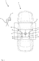
- Fig. 1 an authentication system 1 can be found with which the method according to the invention can be carried out.
- the authentication system 1 is used to authenticate an ID transmitter 2 with respect to a vehicle 3.
- Fig. 1 shows a situation in which the ID transmitter 2 is in the possession of an operator 4.
- the method according to the invention can be used to authenticate the portable ID transmitter 2 to the vehicle 3 so that the operator 4 who carries the portable ID transmitter can access vehicle functions such as starting the vehicle 3 or opening a or more of the vehicle doors.
- the authentication system includes a vehicle-side authentication arrangement 5.
- the authentication arrangement has at least a number of UWB antennas, at least one first UWB antenna 6 and a second UWB antenna 7 being provided, which are spaced from one another on the Vehicle are arranged.
- the first UWB antenna 6 is provided as an integral element of a first UWB transceiver 6 'and the second UWB antenna 7 is provided as an integral element of a second UWB transceiver 7'.
- the authentication arrangement also has a first LF interface 8 ′ with at least one first LF antenna 8 and a second LF interface 9 ′ with a second LF antenna 9 as well as a first proximity sensor 10 and a second proximity sensor 11.
- the first proximity sensor 10 is arranged within a door handle of the left vehicle door, while the second proximity sensor 11 is arranged within the door handle of the passenger door.
- Both the first LF interface 8 and the first proximity sensor 10 are at a smaller distance from the first UWB antenna 6 than from the second UWB antenna 7.
- both the second LF interface 9 and the second proximity sensor 11 are at a smaller distance from the second UWB antenna 7 than from the first UWB antenna 6.
- the UWB transceivers, the LF interfaces and the proximity sensors are coupled to a control device 12 on the motor vehicle side, and via this also to one another.
- the motor vehicle control device 12 is suitable as a control means of the authentication arrangement to control and monitor a method according to the invention and its developments.
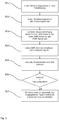
- an LF communication between the first LF interface and the ID transmitter and the second LF interface and the ID transmitter is carried out in a first step. This can take place, for example, in response to an actuation of a proximity sensor or as a result of pollen, this being of secondary importance for the basic functioning of the method sequence shown.
- the ID transmitter detects a first signal strength of the first LF signal and a second signal strength of the second LF signal. After the first and second signal strengths have been recorded, the ID transmitter transmits the signal strengths Authentication arrangements by means of a message transmitted as part of an LF transmission.
- the recorded data are received from a control means of the authentication arrangement, which is coupled both to the LF interfaces and to the UWB antennas, and are transmitted to the vehicle-mounted control device for evaluation. Alternatively, the evaluation could also take place in the key.
- the control device generates a list in which that one of the UWB antennas is selected for the first control of the UWB antenna that is assigned to that LF interface that sent the LF signal with the highest of the LF signal strengths.
- a UWB antenna was selected from the number of UWB antennas as the selected UWB antenna. The selection was made as a function of a received signal strength, for example an RSSI value, of the first LF signal that was sent between the ID transmitter and the authentication arrangement.
- the second UWB antenna has been designated as the second selected UWB antenna, so that the list includes a number of selected antennas.
- the first UWB antenna UWB 1
- UWB 1 is first switched from a non-transmit and / or receive-ready state to a transmit-ready state by controlling the first UWB antenna from the central control device will.
- the first UWB antenna sends a first UWB signal to the ID transmitter.
- the UWB signal is then received by a UWB transceiver of the ID transmitter and answered with a UWB response signal.
- the signal is received by the first UWB antenna in step 204.
- the control device determines the transit time that the UWB signal required on the way to the ID transmitter and also on the return route from the ID transmitter, with a corresponding calculation time within the ID transmitter being known to the control device and thus from the actually recorded Duration can be deducted.
- the running time is calculated by the central control device and in step 206 it is checked whether the running time of the UWB signal is less than a predetermined maximum running time. If this is the case, the ID transmitter for the authentication system is considered to be located within the room in which the vehicle function is enabled (secure bubble). Furthermore, the signal has not been compromised, for example by a relay station attack.
- the next item in the list is the second UWB antenna.
- the second UWB antenna is therefore then activated as the second selected antenna, so that a runtime measurement is initiated again by the second UWB interface.
- the necessary prerequisite for the authentication of the ID transmitter is fulfilled.
- any necessary other requirements are checked, for example via an exchange of cryptographic information, and the authentication is completed when the cryptographic information is successfully evaluated.
- the procedural sequence to be taken differs from that in Fig. 2 illustrated method sequence in that in step 301 an approach of the operator is detected by the first proximity sensor.
- the first proximity sensor outputs an proximity signal to the central control device in step 302, the control device of the authentication arrangement recognizing which of the proximity sensors has detected the proximity.
- the first proximity sensor has detected an approach, which is why the first UWB antenna is determined as the selected UWB antenna and steps 303 to 307 in one of the Fig. 2 analogous procedure can be carried out.
Landscapes
- Engineering & Computer Science (AREA)
- Computer Security & Cryptography (AREA)
- Computer Networks & Wireless Communication (AREA)
- Signal Processing (AREA)
- Physics & Mathematics (AREA)
- General Physics & Mathematics (AREA)
- Theoretical Computer Science (AREA)
- Mechanical Engineering (AREA)
- Computer Hardware Design (AREA)
- Software Systems (AREA)
- General Engineering & Computer Science (AREA)
- Lock And Its Accessories (AREA)
Claims (14)
- Procédé pour faire fonctionner un système d'authentification (1) d'un véhicule (3) pour authentifier un transpondeur d'identification portable (2) par rapport au véhicule (3) pour permettre des fonctions de véhicule pour un opérateur (4) portant le transpondeur d'identification portable (2),
dans lequel le système d'authentification comprend le transpondeur d'identification portable (2) et un dispositif d'authentification côté véhicule (5), le dispositif d'authentification (5) comprenant un certain nombre d'antennes UWB (6, 7) avec au moins une première antenne UWB (6) et une seconde antenne UWB (7) disposées à une certaine distance l'une de l'autre sur le véhicule (3),
dans lequel le procédé comprend au moins les étapes suivantes :A) sélectionner une antenne UWB (6, 7) parmi le nombre d'antennes UWB (6, 7) du dispositif d'authentification (5) en tant qu'antenne UWB sélectionnée, dans lequel la sélection de l'antenne UWB à l'étape A) comprend la création d'une liste qui spécifie une hiérarchisation des antennes UWB de sorte qu'un ordre des antennes UWB disponibles est déterminé avant qu'une communication UWB soit effectuée, spécifiant un ordre dans lequel les antennes UWB sont adressées, dans lequel la sélection de l'antenne UWB est effectuée au moins- en fonction d'une intensité de signal reçue d'un signal BF transmis entre le transpondeur d'identification (2) et une interface BF (8, 9) du dispositif d'authentification (5), et/ou- en fonction de l'intensité du signal reçu d'un signal RF transmis entre le transpondeur d'identification (2) et une interface RF du dispositif d'authentification,
et/ou- en réponse à un signal de proximité provenant d'un capteur de proximité (10, 11) disposé sur le véhicule (3) ;
dans lequel au moins les étapes B)-E) sont répétées séquentiellement pour chaque antenne UWB de la liste de priorisation, en tenant compte de la priorisation des antennes UWB donnée par la liste, jusqu'à ce qu'une condition de fin prédéterminée soit atteinte,B) commander l'antenne UWB sélectionnée pour effectuer une communication UWB entre le transpondeur d'identification (2) et le dispositif d'authentification (5) ;C) réaliser une communication UWB entre le transpondeur d'identification (2) et le dispositif d'authentification (5) ;D) détecter un retard de propagation d'un signal UWB de la communication UWB entre le transpondeur d'identification (2) et l'antenne UWB sélectionnée ;E) vérifier si le temps de propagation du signal UWB est inférieur à un temps de propagation maximal spécifié. - Procédé selon la revendication 1, caractérisé en ce que les étapes B)-E) sont réalisées avec une première antenne UWB sélectionnée, et,
si le temps de propagation du signal UWB entre le transpondeur d'identification (2) et la première antenne sélectionnée est supérieur à un temps de propagation maximal prédéterminé,
au moins les étapes B)-E) sont réalisées avec une deuxième antenne UWB sélectionnée pour vérifier si le temps de propagation du signal UWB entre le transpondeur (2) et la deuxième antenne sélectionnée est inférieur au temps de propagation maximal prédéterminé représentant une position du transpondeur d'identification (2) dans un espace prédéterminé entourant la deuxième antenne UWB sélectionnée. - Procédé selon la revendication 1 ou selon la revendication 2, caractérisé en ce que la condition de terminaison comprend que le temps de propagation du signal UWB entre le transpondeur d'identification et l'antenne UWB sélectionnée ne dépasse pas un écart maximal prédéterminé pour un sous-nombre prédéterminé du nombre d'antennes UWB.
- Procédé selon l'une quelconque des revendications 1 à 3, caractérisé en ce que, avant une répétition des étapes B)-E), la liste est adaptée.
- Procédé selon la revendication 4, caractérisé en ce qu'une antenne UWB est retirée de la liste avant de répéter les étapes B)-E) si
le retard de propagation du signal UWB dépasse un écart maximal prédéterminé de contrôle du retard de propagation par rapport au retard de propagation des signaux UWB d'un ensemble d'antennes UWB, et/ou
une intensité de signal du signal UWB dépasse un écart de commande d'intensité de signal maximum prédéterminé par rapport à l'intensité de signal des signaux UWB d'un ensemble des antennes UWB. - Procédé selon l'une quelconque des revendications précédentes, caractérisé en ce que
le dispositif d'authentification comprend une première interface LF associée à la première antenne UWB et une seconde interface LF associée à la seconde antenne UWB,
dans lequel une première communication BF avec un premier signal BF est effectuée entre le transpondeur d'identification et la première interface BF, et une seconde communication BF avec un second signal BF est effectuée entre le transpondeur d'identification et la seconde interface BF,
dans lequel le transpondeur d'identification détecte une première intensité de signal du premier signal BF et une seconde intensité de signal du second signal BF et communique les intensités de signal au dispositif d'authentification, dans lequel le dispositif d'authentification sélectionne celle des antennes UWB pour commander en premier l'antenne UWB qui est associée à l'interface BF qui a transmis le signal BF ayant la plus grande des intensités de signal BF. - Procédé selon l'une quelconque des revendications 1 à 5, caractérisé en ce que
le dispositif d'authentification comprend une première interface RF associée à la première antenne UWB et une seconde interface RF associée à la seconde antenne UWB,
dans lequel une première communication RF est effectuée avec un premier signal RF entre le transpondeur d'identification et la première interface RF et une seconde communication RF est effectuée avec un second signal RF entre le transpondeur d'identification et la seconde interface RF,
dans lequel le transpondeur d'identification détecte une première intensité de signal du premier signal RF et une seconde intensité de signal du second signal RF et communique les intensités de signal au dispositif d'authentification, dans lequel le dispositif d'authentification sélectionne celle de la première antenne UWB et de la seconde antenne UWB pour piloter en premier l'antenne UWB qui est associée à l'interface RF qui a transmis le signal RF ayant la plus grande des première et seconde intensités de signal. - Procédé selon l'une quelconque des revendications 1 à 5, caractérisé en ce que
le dispositif d'authentification comprend un premier capteur de proximité associé à la première antenne UWB et un second capteur de proximité associé à la seconde antenne UWB,
dans lequel, lorsque l'un des capteurs de proximité détecte une approche de l'opérateur, ce capteur de proximité émet un signal de proximité identifiant le capteur de proximité, et en ce qu'un moyen de commande du dispositif d'authentification, lorsqu'il détecte le signal de proximité, sélectionne comme antenne UWB sélectionnée celle de la première antenne UWB et de la seconde antenne UWB qui est associée à celui du premier capteur de proximité et du second capteur de proximité qui a émis le signal de proximité. - Procédé selon l'une quelconque des revendications précédentes, caractérisé en ce que la réalisation de la communication UWB est effectuée au moins temporairement en parallèle avec la réalisation d'une communication BF ou d'une communication RF.
- Procédé selon l'une quelconque des revendications précédentes, caractérisé en ce que les temps de propagation des signaux UWB détectés pour permettre des fonctions du véhicule sont considérés comme valables pour une période de temps minimale, et en ce qu'aucune communication UWB n'est effectuée par le dispositif d'authentification pendant la période de temps minimale.
- Procédé selon l'une des revendications précédentes, caractérisé en ce que, après que le contrôle à l'étape E a montré que le temps de propagation du signal UWB de la communication UWB entre le transpondeur d'identification et au moins une antenne UWB sélectionnée qui a lieu pendant l'étape C est inférieur au temps de propagation maximal prédéterminé, le dispositif d'authentification côté véhicule effectue un contrôle de l'authentification du transpondeur sur la base des données d'authentification transmises entre le transpondeur d'identification et le dispositif d'authentification côté véhicule pendant l'étape C et, si le contrôle confirme l'authentification, lance une validation de la fonction.
- Procédé selon l'une quelconque des revendications précédentes, dans lequel,
après que la vérification à l'étape E avec au moins une antenne sélectionnée a confirmé la présence du transpondeur d'identification dans une distance maximale de l'antenne sélectionnée, des informations cryptographiques sont transmises au moyen d'une communication HF, d'une communication LF et/ou d'une communication UWB entre le transpondeur et une unité de commande côté véhicule du système d'authentification, l'information cryptographique, de préférence transmise après l'étape E, est évaluée et l'authentification du transpondeur d'identification est achevée dans l'unité de commande du côté du véhicule à moteur sur la base de l'évaluation de l'information cryptographique et, après une authentification réussie, la libération de la fonction ou des fonctions est initiée. - Procédé selon l'une quelconque des revendications précédentes, dans lequel une activation de la fonction pour l'opérateur est inhibée côté véhicule tant que, dans une période de temps maximale prédéterminée, le contrôle à l'étape E avec au moins une antenne sélectionnée n'a pas confirmé la présence du transpondeur dans une distance maximale de l'antenne sélectionnée.
- Système d'authentification (2, 5) d'un véhicule (3) pour authentifier un transpondeur d'identification portable (2) au véhicule (3) afin de permettre les fonctions du véhicule pour un opérateur (4) portant le transpondeur d'identification portable (2),
dans lequel le système d'authentification (2, 5) comprend le transpondeur d'identification portable (2) et un dispositif d'authentification (5) côté véhicule, dans lequel le transpondeur d'identification portable (2) comprend au moins une première interface UWB de transpondeur d'identification avec une antenne UWB de transpondeur d'identification et le dispositif d'authentification (5) comprend au moins une première interface UWB de véhicule (6') avec une première antenne UWB (6) et une deuxième interface UWB de véhicule (7') avec une deuxième antenne UWB (7) qui sont disposées sur le véhicule à distance l'une de l'autre, et la première interface UWB de l'émetteur d'identification et les interfaces UWB du véhicule (6', 7') étant configurées pour une communication UWB entre elles,
dans lequel un moyen de commande (12) du dispositif d'authentification (5) est adapté pour exécuter un procédé selon l'une quelconque des revendications précédentes.
Applications Claiming Priority (2)
| Application Number | Priority Date | Filing Date | Title |
|---|---|---|---|
| DE102017109293.5A DE102017109293A1 (de) | 2017-04-28 | 2017-04-28 | Verfahren zum Betreiben eines Authentifizierungssystems und Authentifizierungssystem |
| PCT/EP2018/057235 WO2018197116A1 (fr) | 2017-04-28 | 2018-03-22 | Procédé de fonctionnement d'un système d'authentification et système d'authentification |
Publications (2)
| Publication Number | Publication Date |
|---|---|
| EP3580731A1 EP3580731A1 (fr) | 2019-12-18 |
| EP3580731B1 true EP3580731B1 (fr) | 2021-07-21 |
Family
ID=61801922
Family Applications (1)
| Application Number | Title | Priority Date | Filing Date |
|---|---|---|---|
| EP18713855.7A Active EP3580731B1 (fr) | 2017-04-28 | 2018-03-22 | Procédé de fonctionnement d'un système d'authentification et système d'authentification |
Country Status (5)
| Country | Link |
|---|---|
| US (1) | US11277742B2 (fr) |
| EP (1) | EP3580731B1 (fr) |
| CN (1) | CN110574080B (fr) |
| DE (1) | DE102017109293A1 (fr) |
| WO (1) | WO2018197116A1 (fr) |
Families Citing this family (12)
| Publication number | Priority date | Publication date | Assignee | Title |
|---|---|---|---|---|
| US20210281124A1 (en) * | 2020-03-06 | 2021-09-09 | Proxy, Inc. | Authorized wireless charging methods and apparatus |
| CN111784888B (zh) * | 2020-07-21 | 2022-05-17 | 上海华虹计通智能系统股份有限公司 | 一种分体式车载人员定位设备的同步方法及系统 |
| US11449691B2 (en) * | 2020-08-20 | 2022-09-20 | Assa Abloy Ab | Relay attack detection for interfaces using command-response pair |
| JP2022052119A (ja) * | 2020-09-23 | 2022-04-04 | 株式会社東海理化電機製作所 | システム、制御装置、処理装置、およびプログラム |
| JP2022052118A (ja) * | 2020-09-23 | 2022-04-04 | 株式会社東海理化電機製作所 | システム、制御装置、処理装置、およびプログラム |
| JP7396317B2 (ja) * | 2021-03-09 | 2023-12-12 | トヨタ自動車株式会社 | 認証装置、車両、認証方法及び認証プログラム |
| CN113221094B (zh) * | 2021-03-11 | 2024-10-29 | 北京小米移动软件有限公司 | 身份识别方法及装置、设备及存储介质 |
| JP2023042216A (ja) * | 2021-09-14 | 2023-03-27 | 株式会社東海理化電機製作所 | 通信装置 |
| FR3139154A1 (fr) * | 2022-08-25 | 2024-03-01 | Continental Automotive Technologies GmbH | Procédé de verrouillage et de déverrouillage d’une portière de véhicule automobile et dispositif de verrouillage et de déverrouillage associé |
| DE102022124176A1 (de) | 2022-09-21 | 2024-03-21 | Marquardt Gmbh | Verfahren zum Betreiben eines Authentifizierungssystems sowie Authentifizierungssystems mit genau einem UWB-Modul |
| DE102022124178A1 (de) | 2022-09-21 | 2024-03-21 | Marquardt Gmbh | Verfahren zum Betreiben eines Authentifizierungssystems sowie Authentifizierungssystems mit einer Vielzahl von UWB-Antennen |
| DE102022124412A1 (de) | 2022-09-22 | 2024-03-28 | Marquardt Gmbh | Authentifizierungssystem zur Authentifizierung eines Schlüssels gegenüber dem Fahrzeug sowie zugehöriges Verfahren |
Family Cites Families (22)
| Publication number | Priority date | Publication date | Assignee | Title |
|---|---|---|---|---|
| US5973611A (en) | 1995-03-27 | 1999-10-26 | Ut Automotive Dearborn, Inc. | Hands-free remote entry system |
| JP3533966B2 (ja) | 1998-06-18 | 2004-06-07 | トヨタ自動車株式会社 | 車両制御システム |
| JP4214199B2 (ja) * | 2001-11-19 | 2009-01-28 | 株式会社デンソー | 車両のドアアンロック装置 |
| WO2003050370A1 (fr) * | 2001-12-10 | 2003-06-19 | Omron Co., Ltd. | Capteur d'objet et controleur |
| DE10306568A1 (de) | 2003-02-17 | 2004-08-26 | Delphi Technologies, Inc., Troy | Elektronische Schließvorrichtung |
| US7915998B2 (en) | 2005-11-11 | 2011-03-29 | Fujitsu Ten Limited | Vehicle control system and vehicle control apparatus |
| JP5818280B2 (ja) | 2012-02-09 | 2015-11-18 | Necソリューションイノベータ株式会社 | 情報処理システム |
| CN102602363A (zh) | 2012-03-27 | 2012-07-25 | 华南理工大学 | 基于超宽带的车辆无钥匙进入、启动与闭锁方法及装置 |
| US20130342379A1 (en) * | 2012-06-25 | 2013-12-26 | Lear Corporation | Vehicle Remote Function System and Method |
| GB201219261D0 (en) | 2012-10-26 | 2012-12-12 | Jaguar Cars | Vehicle access system and method |
| US9852560B2 (en) * | 2013-03-08 | 2017-12-26 | Lear Corporation | Vehicle remote function system and method for effectuating vehicle operations based on vehicle FOB movement |
| US8930045B2 (en) * | 2013-05-01 | 2015-01-06 | Delphi Technologies, Inc. | Relay attack prevention for passive entry passive start (PEPS) vehicle security systems |
| JP6137687B2 (ja) | 2013-12-12 | 2017-05-31 | アルプス電気株式会社 | キーレスエントリーシステム |
| FR3026212B1 (fr) | 2014-09-24 | 2018-05-25 | Valeo Comfort And Driving Assistance | Dispositif de controle de verrouillage/deverrouillage et/ou de demarrage d'un vehicule |
| WO2016059451A1 (fr) | 2014-10-15 | 2016-04-21 | Continental Automotive Gmbh | Procédé et système de détection d'attaque par relais pour système pase |
| US9485609B2 (en) | 2015-02-06 | 2016-11-01 | Nxp B.V. | Pulse frequency control for wireless communications and ranging |
| US9566945B2 (en) | 2015-05-14 | 2017-02-14 | Lear Corporation | Passive entry passive start (PEPS) system with relay attack prevention |
| CN108778855A (zh) * | 2016-02-26 | 2018-11-09 | 胡夫·许尔斯贝克和福斯特有限及两合公司 | 激活车辆安全系统的至少一个安全功能的方法 |
| KR101718072B1 (ko) | 2016-03-30 | 2017-03-20 | 현대자동차주식회사 | 차량 및 차량의 제어방법 |
| EP3306576B1 (fr) | 2016-10-05 | 2023-03-15 | The Swatch Group Research and Development Ltd | Procédé et système d'accès securisé à un espace déterminé au moyen d'un objet portable |
| EP3335942B1 (fr) | 2016-12-14 | 2019-11-20 | Nxp B.V. | Système d'accès sécurisé de véhicule, clé, véhicule et procédé associé |
| DE102017201308B4 (de) * | 2017-01-27 | 2020-07-02 | Continental Automotive Gmbh | Verfahren zum Verifizieren eines vorgegebenen räumlichen Maximalabstands eines Funkschlüssels bezüglich eines Kraftfahrzeugs sowie Steuervorrichtung, Kraftfahrzeug und Funkschlüssel |
-
2017
- 2017-04-28 DE DE102017109293.5A patent/DE102017109293A1/de not_active Withdrawn
-
2018
- 2018-03-22 WO PCT/EP2018/057235 patent/WO2018197116A1/fr unknown
- 2018-03-22 EP EP18713855.7A patent/EP3580731B1/fr active Active
- 2018-03-22 CN CN201880028176.4A patent/CN110574080B/zh active Active
- 2018-03-22 US US16/608,607 patent/US11277742B2/en active Active
Also Published As
| Publication number | Publication date |
|---|---|
| CN110574080B (zh) | 2021-09-17 |
| WO2018197116A1 (fr) | 2018-11-01 |
| EP3580731A1 (fr) | 2019-12-18 |
| DE102017109293A1 (de) | 2018-10-31 |
| US11277742B2 (en) | 2022-03-15 |
| CN110574080A (zh) | 2019-12-13 |
| US20210120407A1 (en) | 2021-04-22 |
Similar Documents
| Publication | Publication Date | Title |
|---|---|---|
| EP3580731B1 (fr) | Procédé de fonctionnement d'un système d'authentification et système d'authentification | |
| EP3571676B1 (fr) | Système d'authentification d'un véhicule | |
| EP3472809B1 (fr) | Procédé de commande de l'accès à un véhicule | |
| DE112019001466T5 (de) | Entfernungsmesssystem | |
| DE102016223252B4 (de) | Zugangsvorrichtung für ein Fahrzeug | |
| DE102016207997A1 (de) | Sicherer Zugang zu einem Fahrzeug | |
| WO2019149399A1 (fr) | Système de communication d'un véhicule | |
| DE102017120524A1 (de) | Tragbarer ID-Geber für ein Authentifizierungssystem und Verfahren zum Betreiben eines Authentifizierungssystems | |
| EP3504688A1 (fr) | Dispositif de fermeture à clé radio pour un véhicule automobile, véhicule automobile et procédé permettant de faire fonctionner le dispositif de fermeture | |
| DE102017207830A1 (de) | Vorrichtung und Verfahren zur Bestimmung einer Distanz | |
| EP3396640A1 (fr) | Émetteur d'identification portable pour un système d'authentification et procédé de fonctionnement d'un système d'authentification | |
| EP3569455A1 (fr) | Protection contre un attaque par relais | |
| EP3734559A1 (fr) | Système de sécurité pour un véhicule | |
| DE102008007842B3 (de) | Synchronisation der Kommunikation zwischen Identifikationsgeber und Fahrzeugstation einer Zugangsvorrichtung | |
| DE102014220399B4 (de) | Verfahren und Vorrichtung zur Zugangs- und Startverifizierung in einem Fahrzeug | |
| WO2024061582A1 (fr) | Procédé de fonctionnement d'un système d'authentification, et système d'authentification comportant exactement un module uwb | |
| WO2024061520A1 (fr) | Procédé de fonctionnement d'un système d'authentification et système d'authentification comprenant une pluralité d'antennes uwb | |
| EP3774456A1 (fr) | Système pour un véhicule | |
| EP3395622A1 (fr) | Procédé de fonctionnement d'un système d'authentification, système d'authentification et utilisation | |
| EP3883825B1 (fr) | Dispositif d'accès pour un véhicule | |
| DE102019211798B4 (de) | Zugangsanordnung für ein Fahrzeug | |
| DE102017121762A1 (de) | Verfahren zur Aktivierung mindestens einer Funktion eines Fahrzeugs | |
| DE102017112942A1 (de) | Verfahren zum Betreiben eines Authentifizierungssystems, Authentifizierungssystem und Verwendung | |
| EP3484753B1 (fr) | Procédé pour déclencher une fonction d'un véhicule à moteur | |
| WO2024227579A1 (fr) | Dispositif pour véhicule automobile permettant de faire fonctionner un module sans fil dans différents modes de fonctionnement en alternance |
Legal Events
| Date | Code | Title | Description |
|---|---|---|---|
| STAA | Information on the status of an ep patent application or granted ep patent |
Free format text: STATUS: UNKNOWN |
|
| STAA | Information on the status of an ep patent application or granted ep patent |
Free format text: STATUS: THE INTERNATIONAL PUBLICATION HAS BEEN MADE |
|
| PUAI | Public reference made under article 153(3) epc to a published international application that has entered the european phase |
Free format text: ORIGINAL CODE: 0009012 |
|
| STAA | Information on the status of an ep patent application or granted ep patent |
Free format text: STATUS: REQUEST FOR EXAMINATION WAS MADE |
|
| 17P | Request for examination filed |
Effective date: 20190909 |
|
| AK | Designated contracting states |
Kind code of ref document: A1 Designated state(s): AL AT BE BG CH CY CZ DE DK EE ES FI FR GB GR HR HU IE IS IT LI LT LU LV MC MK MT NL NO PL PT RO RS SE SI SK SM TR |
|
| AX | Request for extension of the european patent |
Extension state: BA ME |
|
| DAV | Request for validation of the european patent (deleted) | ||
| DAX | Request for extension of the european patent (deleted) | ||
| GRAP | Despatch of communication of intention to grant a patent |
Free format text: ORIGINAL CODE: EPIDOSNIGR1 |
|
| STAA | Information on the status of an ep patent application or granted ep patent |
Free format text: STATUS: GRANT OF PATENT IS INTENDED |
|
| INTG | Intention to grant announced |
Effective date: 20210517 |
|
| GRAS | Grant fee paid |
Free format text: ORIGINAL CODE: EPIDOSNIGR3 |
|
| GRAA | (expected) grant |
Free format text: ORIGINAL CODE: 0009210 |
|
| STAA | Information on the status of an ep patent application or granted ep patent |
Free format text: STATUS: THE PATENT HAS BEEN GRANTED |
|
| AK | Designated contracting states |
Kind code of ref document: B1 Designated state(s): AL AT BE BG CH CY CZ DE DK EE ES FI FR GB GR HR HU IE IS IT LI LT LU LV MC MK MT NL NO PL PT RO RS SE SI SK SM TR |
|
| REG | Reference to a national code |
Ref country code: GB Ref legal event code: FG4D Free format text: NOT ENGLISH |
|
| REG | Reference to a national code |
Ref country code: CH Ref legal event code: EP |
|
| REG | Reference to a national code |
Ref country code: DE Ref legal event code: R096 Ref document number: 502018006217 Country of ref document: DE |
|
| REG | Reference to a national code |
Ref country code: AT Ref legal event code: REF Ref document number: 1413293 Country of ref document: AT Kind code of ref document: T Effective date: 20210815 |
|
| REG | Reference to a national code |
Ref country code: IE Ref legal event code: FG4D Free format text: LANGUAGE OF EP DOCUMENT: GERMAN |
|
| REG | Reference to a national code |
Ref country code: LT Ref legal event code: MG9D |
|
| REG | Reference to a national code |
Ref country code: NL Ref legal event code: MP Effective date: 20210721 |
|
| PG25 | Lapsed in a contracting state [announced via postgrant information from national office to epo] |
Ref country code: SE Free format text: LAPSE BECAUSE OF FAILURE TO SUBMIT A TRANSLATION OF THE DESCRIPTION OR TO PAY THE FEE WITHIN THE PRESCRIBED TIME-LIMIT Effective date: 20210721 Ref country code: RS Free format text: LAPSE BECAUSE OF FAILURE TO SUBMIT A TRANSLATION OF THE DESCRIPTION OR TO PAY THE FEE WITHIN THE PRESCRIBED TIME-LIMIT Effective date: 20210721 Ref country code: HR Free format text: LAPSE BECAUSE OF FAILURE TO SUBMIT A TRANSLATION OF THE DESCRIPTION OR TO PAY THE FEE WITHIN THE PRESCRIBED TIME-LIMIT Effective date: 20210721 Ref country code: FI Free format text: LAPSE BECAUSE OF FAILURE TO SUBMIT A TRANSLATION OF THE DESCRIPTION OR TO PAY THE FEE WITHIN THE PRESCRIBED TIME-LIMIT Effective date: 20210721 Ref country code: ES Free format text: LAPSE BECAUSE OF FAILURE TO SUBMIT A TRANSLATION OF THE DESCRIPTION OR TO PAY THE FEE WITHIN THE PRESCRIBED TIME-LIMIT Effective date: 20210721 Ref country code: PT Free format text: LAPSE BECAUSE OF FAILURE TO SUBMIT A TRANSLATION OF THE DESCRIPTION OR TO PAY THE FEE WITHIN THE PRESCRIBED TIME-LIMIT Effective date: 20211122 Ref country code: NO Free format text: LAPSE BECAUSE OF FAILURE TO SUBMIT A TRANSLATION OF THE DESCRIPTION OR TO PAY THE FEE WITHIN THE PRESCRIBED TIME-LIMIT Effective date: 20211021 Ref country code: NL Free format text: LAPSE BECAUSE OF FAILURE TO SUBMIT A TRANSLATION OF THE DESCRIPTION OR TO PAY THE FEE WITHIN THE PRESCRIBED TIME-LIMIT Effective date: 20210721 Ref country code: LT Free format text: LAPSE BECAUSE OF FAILURE TO SUBMIT A TRANSLATION OF THE DESCRIPTION OR TO PAY THE FEE WITHIN THE PRESCRIBED TIME-LIMIT Effective date: 20210721 Ref country code: BG Free format text: LAPSE BECAUSE OF FAILURE TO SUBMIT A TRANSLATION OF THE DESCRIPTION OR TO PAY THE FEE WITHIN THE PRESCRIBED TIME-LIMIT Effective date: 20211021 |
|
| PG25 | Lapsed in a contracting state [announced via postgrant information from national office to epo] |
Ref country code: PL Free format text: LAPSE BECAUSE OF FAILURE TO SUBMIT A TRANSLATION OF THE DESCRIPTION OR TO PAY THE FEE WITHIN THE PRESCRIBED TIME-LIMIT Effective date: 20210721 Ref country code: LV Free format text: LAPSE BECAUSE OF FAILURE TO SUBMIT A TRANSLATION OF THE DESCRIPTION OR TO PAY THE FEE WITHIN THE PRESCRIBED TIME-LIMIT Effective date: 20210721 Ref country code: GR Free format text: LAPSE BECAUSE OF FAILURE TO SUBMIT A TRANSLATION OF THE DESCRIPTION OR TO PAY THE FEE WITHIN THE PRESCRIBED TIME-LIMIT Effective date: 20211022 |
|
| REG | Reference to a national code |
Ref country code: DE Ref legal event code: R097 Ref document number: 502018006217 Country of ref document: DE |
|
| PG25 | Lapsed in a contracting state [announced via postgrant information from national office to epo] |
Ref country code: DK Free format text: LAPSE BECAUSE OF FAILURE TO SUBMIT A TRANSLATION OF THE DESCRIPTION OR TO PAY THE FEE WITHIN THE PRESCRIBED TIME-LIMIT Effective date: 20210721 |
|
| PLBE | No opposition filed within time limit |
Free format text: ORIGINAL CODE: 0009261 |
|
| STAA | Information on the status of an ep patent application or granted ep patent |
Free format text: STATUS: NO OPPOSITION FILED WITHIN TIME LIMIT |
|
| PG25 | Lapsed in a contracting state [announced via postgrant information from national office to epo] |
Ref country code: SM Free format text: LAPSE BECAUSE OF FAILURE TO SUBMIT A TRANSLATION OF THE DESCRIPTION OR TO PAY THE FEE WITHIN THE PRESCRIBED TIME-LIMIT Effective date: 20210721 Ref country code: SK Free format text: LAPSE BECAUSE OF FAILURE TO SUBMIT A TRANSLATION OF THE DESCRIPTION OR TO PAY THE FEE WITHIN THE PRESCRIBED TIME-LIMIT Effective date: 20210721 Ref country code: RO Free format text: LAPSE BECAUSE OF FAILURE TO SUBMIT A TRANSLATION OF THE DESCRIPTION OR TO PAY THE FEE WITHIN THE PRESCRIBED TIME-LIMIT Effective date: 20210721 Ref country code: EE Free format text: LAPSE BECAUSE OF FAILURE TO SUBMIT A TRANSLATION OF THE DESCRIPTION OR TO PAY THE FEE WITHIN THE PRESCRIBED TIME-LIMIT Effective date: 20210721 Ref country code: CZ Free format text: LAPSE BECAUSE OF FAILURE TO SUBMIT A TRANSLATION OF THE DESCRIPTION OR TO PAY THE FEE WITHIN THE PRESCRIBED TIME-LIMIT Effective date: 20210721 Ref country code: AL Free format text: LAPSE BECAUSE OF FAILURE TO SUBMIT A TRANSLATION OF THE DESCRIPTION OR TO PAY THE FEE WITHIN THE PRESCRIBED TIME-LIMIT Effective date: 20210721 |
|
| 26N | No opposition filed |
Effective date: 20220422 |
|
| PG25 | Lapsed in a contracting state [announced via postgrant information from national office to epo] |
Ref country code: IT Free format text: LAPSE BECAUSE OF FAILURE TO SUBMIT A TRANSLATION OF THE DESCRIPTION OR TO PAY THE FEE WITHIN THE PRESCRIBED TIME-LIMIT Effective date: 20210721 |
|
| PG25 | Lapsed in a contracting state [announced via postgrant information from national office to epo] |
Ref country code: MC Free format text: LAPSE BECAUSE OF FAILURE TO SUBMIT A TRANSLATION OF THE DESCRIPTION OR TO PAY THE FEE WITHIN THE PRESCRIBED TIME-LIMIT Effective date: 20210721 |
|
| REG | Reference to a national code |
Ref country code: CH Ref legal event code: PL |
|
| GBPC | Gb: european patent ceased through non-payment of renewal fee |
Effective date: 20220322 |
|
| REG | Reference to a national code |
Ref country code: BE Ref legal event code: MM Effective date: 20220331 |
|
| PG25 | Lapsed in a contracting state [announced via postgrant information from national office to epo] |
Ref country code: LU Free format text: LAPSE BECAUSE OF NON-PAYMENT OF DUE FEES Effective date: 20220322 Ref country code: LI Free format text: LAPSE BECAUSE OF NON-PAYMENT OF DUE FEES Effective date: 20220331 Ref country code: IE Free format text: LAPSE BECAUSE OF NON-PAYMENT OF DUE FEES Effective date: 20220322 Ref country code: GB Free format text: LAPSE BECAUSE OF NON-PAYMENT OF DUE FEES Effective date: 20220322 Ref country code: CH Free format text: LAPSE BECAUSE OF NON-PAYMENT OF DUE FEES Effective date: 20220331 |
|
| PG25 | Lapsed in a contracting state [announced via postgrant information from national office to epo] |
Ref country code: BE Free format text: LAPSE BECAUSE OF NON-PAYMENT OF DUE FEES Effective date: 20220331 |
|
| P01 | Opt-out of the competence of the unified patent court (upc) registered |
Effective date: 20230507 |
|
| PG25 | Lapsed in a contracting state [announced via postgrant information from national office to epo] |
Ref country code: MK Free format text: LAPSE BECAUSE OF FAILURE TO SUBMIT A TRANSLATION OF THE DESCRIPTION OR TO PAY THE FEE WITHIN THE PRESCRIBED TIME-LIMIT Effective date: 20210721 Ref country code: CY Free format text: LAPSE BECAUSE OF FAILURE TO SUBMIT A TRANSLATION OF THE DESCRIPTION OR TO PAY THE FEE WITHIN THE PRESCRIBED TIME-LIMIT Effective date: 20210721 |
|
| PGFP | Annual fee paid to national office [announced via postgrant information from national office to epo] |
Ref country code: DE Payment date: 20240331 Year of fee payment: 7 |
|
| REG | Reference to a national code |
Ref country code: AT Ref legal event code: MM01 Ref document number: 1413293 Country of ref document: AT Kind code of ref document: T Effective date: 20230322 |
|
| PG25 | Lapsed in a contracting state [announced via postgrant information from national office to epo] |
Ref country code: HU Free format text: LAPSE BECAUSE OF FAILURE TO SUBMIT A TRANSLATION OF THE DESCRIPTION OR TO PAY THE FEE WITHIN THE PRESCRIBED TIME-LIMIT; INVALID AB INITIO Effective date: 20180322 |
|
| PGFP | Annual fee paid to national office [announced via postgrant information from national office to epo] |
Ref country code: FR Payment date: 20240320 Year of fee payment: 7 |
|
| PG25 | Lapsed in a contracting state [announced via postgrant information from national office to epo] |
Ref country code: TR Free format text: LAPSE BECAUSE OF FAILURE TO SUBMIT A TRANSLATION OF THE DESCRIPTION OR TO PAY THE FEE WITHIN THE PRESCRIBED TIME-LIMIT Effective date: 20210721 |
|
| PG25 | Lapsed in a contracting state [announced via postgrant information from national office to epo] |
Ref country code: AT Free format text: LAPSE BECAUSE OF NON-PAYMENT OF DUE FEES Effective date: 20230322 |
|
| PG25 | Lapsed in a contracting state [announced via postgrant information from national office to epo] |
Ref country code: AT Free format text: LAPSE BECAUSE OF NON-PAYMENT OF DUE FEES Effective date: 20230322 |
|
| PG25 | Lapsed in a contracting state [announced via postgrant information from national office to epo] |
Ref country code: MT Free format text: LAPSE BECAUSE OF FAILURE TO SUBMIT A TRANSLATION OF THE DESCRIPTION OR TO PAY THE FEE WITHIN THE PRESCRIBED TIME-LIMIT Effective date: 20210721 |