EP3580512B1 - Furnace assembly for a metal-making process - Google Patents
Furnace assembly for a metal-making process Download PDFInfo
- Publication number
- EP3580512B1 EP3580512B1 EP17704737.0A EP17704737A EP3580512B1 EP 3580512 B1 EP3580512 B1 EP 3580512B1 EP 17704737 A EP17704737 A EP 17704737A EP 3580512 B1 EP3580512 B1 EP 3580512B1
- Authority
- EP
- European Patent Office
- Prior art keywords
- electric arc
- furnace
- arc furnace
- electromagnetic stirrer
- assembly
- Prior art date
- Legal status (The legal status is an assumption and is not a legal conclusion. Google has not performed a legal analysis and makes no representation as to the accuracy of the status listed.)
- Active
Links
Images
Classifications
-
- F—MECHANICAL ENGINEERING; LIGHTING; HEATING; WEAPONS; BLASTING
- F27—FURNACES; KILNS; OVENS; RETORTS
- F27B—FURNACES, KILNS, OVENS OR RETORTS IN GENERAL; OPEN SINTERING OR LIKE APPARATUS
- F27B3/00—Hearth-type furnaces, e.g. of reverberatory type; Electric arc furnaces ; Tank furnaces
- F27B3/08—Hearth-type furnaces, e.g. of reverberatory type; Electric arc furnaces ; Tank furnaces heated electrically, with or without any other source of heat
- F27B3/085—Arc furnaces
-
- F—MECHANICAL ENGINEERING; LIGHTING; HEATING; WEAPONS; BLASTING
- F27—FURNACES; KILNS; OVENS; RETORTS
- F27B—FURNACES, KILNS, OVENS OR RETORTS IN GENERAL; OPEN SINTERING OR LIKE APPARATUS
- F27B3/00—Hearth-type furnaces, e.g. of reverberatory type; Electric arc furnaces ; Tank furnaces
- F27B3/08—Hearth-type furnaces, e.g. of reverberatory type; Electric arc furnaces ; Tank furnaces heated electrically, with or without any other source of heat
-
- F—MECHANICAL ENGINEERING; LIGHTING; HEATING; WEAPONS; BLASTING
- F27—FURNACES; KILNS; OVENS; RETORTS
- F27B—FURNACES, KILNS, OVENS OR RETORTS IN GENERAL; OPEN SINTERING OR LIKE APPARATUS
- F27B3/00—Hearth-type furnaces, e.g. of reverberatory type; Electric arc furnaces ; Tank furnaces
- F27B3/10—Details, accessories or equipment, e.g. dust-collectors, specially adapted for hearth-type furnaces
-
- F—MECHANICAL ENGINEERING; LIGHTING; HEATING; WEAPONS; BLASTING
- F27—FURNACES; KILNS; OVENS; RETORTS
- F27B—FURNACES, KILNS, OVENS OR RETORTS IN GENERAL; OPEN SINTERING OR LIKE APPARATUS
- F27B3/00—Hearth-type furnaces, e.g. of reverberatory type; Electric arc furnaces ; Tank furnaces
- F27B3/10—Details, accessories or equipment, e.g. dust-collectors, specially adapted for hearth-type furnaces
- F27B3/18—Arrangements of devices for charging
-
- F—MECHANICAL ENGINEERING; LIGHTING; HEATING; WEAPONS; BLASTING
- F27—FURNACES; KILNS; OVENS; RETORTS
- F27D—DETAILS OR ACCESSORIES OF FURNACES, KILNS, OVENS OR RETORTS, IN SO FAR AS THEY ARE OF KINDS OCCURRING IN MORE THAN ONE KIND OF FURNACE
- F27D11/00—Arrangement of elements for electric heating in or on furnaces
- F27D11/12—Arrangement of elements for electric heating in or on furnaces with electromagnetic fields acting directly on the material being heated
-
- F—MECHANICAL ENGINEERING; LIGHTING; HEATING; WEAPONS; BLASTING
- F27—FURNACES; KILNS; OVENS; RETORTS
- F27D—DETAILS OR ACCESSORIES OF FURNACES, KILNS, OVENS OR RETORTS, IN SO FAR AS THEY ARE OF KINDS OCCURRING IN MORE THAN ONE KIND OF FURNACE
- F27D27/00—Stirring devices for molten material
-
- F—MECHANICAL ENGINEERING; LIGHTING; HEATING; WEAPONS; BLASTING
- F27—FURNACES; KILNS; OVENS; RETORTS
- F27B—FURNACES, KILNS, OVENS OR RETORTS IN GENERAL; OPEN SINTERING OR LIKE APPARATUS
- F27B3/00—Hearth-type furnaces, e.g. of reverberatory type; Electric arc furnaces ; Tank furnaces
- F27B3/10—Details, accessories or equipment, e.g. dust-collectors, specially adapted for hearth-type furnaces
- F27B3/28—Arrangement of controlling, monitoring, alarm or the like devices
-
- F—MECHANICAL ENGINEERING; LIGHTING; HEATING; WEAPONS; BLASTING
- F27—FURNACES; KILNS; OVENS; RETORTS
- F27D—DETAILS OR ACCESSORIES OF FURNACES, KILNS, OVENS OR RETORTS, IN SO FAR AS THEY ARE OF KINDS OCCURRING IN MORE THAN ONE KIND OF FURNACE
- F27D3/00—Charging; Discharging; Manipulation of charge
- F27D3/16—Introducing a fluid jet or current into the charge
- F27D2003/167—Introducing a fluid jet or current into the charge the fluid being a neutral gas
-
- F—MECHANICAL ENGINEERING; LIGHTING; HEATING; WEAPONS; BLASTING
- F27—FURNACES; KILNS; OVENS; RETORTS
- F27D—DETAILS OR ACCESSORIES OF FURNACES, KILNS, OVENS OR RETORTS, IN SO FAR AS THEY ARE OF KINDS OCCURRING IN MORE THAN ONE KIND OF FURNACE
- F27D19/00—Arrangements of controlling devices
- F27D2019/0006—Monitoring the characteristics (composition, quantities, temperature, pressure) of at least one of the gases of the kiln atmosphere and using it as a controlling value
-
- F—MECHANICAL ENGINEERING; LIGHTING; HEATING; WEAPONS; BLASTING
- F27—FURNACES; KILNS; OVENS; RETORTS
- F27M—INDEXING SCHEME RELATING TO ASPECTS OF THE CHARGES OR FURNACES, KILNS, OVENS OR RETORTS
- F27M2003/00—Type of treatment of the charge
- F27M2003/13—Smelting
-
- Y—GENERAL TAGGING OF NEW TECHNOLOGICAL DEVELOPMENTS; GENERAL TAGGING OF CROSS-SECTIONAL TECHNOLOGIES SPANNING OVER SEVERAL SECTIONS OF THE IPC; TECHNICAL SUBJECTS COVERED BY FORMER USPC CROSS-REFERENCE ART COLLECTIONS [XRACs] AND DIGESTS
- Y02—TECHNOLOGIES OR APPLICATIONS FOR MITIGATION OR ADAPTATION AGAINST CLIMATE CHANGE
- Y02P—CLIMATE CHANGE MITIGATION TECHNOLOGIES IN THE PRODUCTION OR PROCESSING OF GOODS
- Y02P10/00—Technologies related to metal processing
- Y02P10/20—Recycling
Definitions
- the present disclosure generally relates to metal-making and in particular to a furnace assembly for a metal-making process.
- Flat bath operation is a process of continuously feeding or small-bucket charging of metallic materials such as scrap, pig iron, direct reduced iron (DRI), hot metal, or hot briquetted iron (HBI), into the furnace bath of an electric arc furnace (EAF) without opening the furnace roof.
- metallic materials such as scrap, pig iron, direct reduced iron (DRI), hot metal, or hot briquetted iron (HBI)
- EAF electric arc furnace
- This process provides high energy efficiency and less electrode consumption.
- porous plugs with direct or indirect gas purging are installed in the bottom refractory. Normally 3-5 porous plugs are needed depending on the furnace size.
- the stirring intensity is controlled by the gas, typically nitrogen or argon, and by flow rate and pressure.
- the document EP2751510 is an example of a furnace assembly of the technical field.
- an object of the present disclosure is to provide a furnace assembly for a metal-making process which solves, or at least mitigates, the problems of the prior art.
- An effect which may be obtainable thereby is that stirring within the entire melt bath with no dead zone or essentially no dead zone in the bath may be provided. Hence, more efficient metal-making using an electric arc furnace configured for flat bath operation may be provided.
- the long lifespan of the electromagnetic stirrer coil requires almost no maintenance.
- the electromagnetic stirring reduces the melt surface superheat and the heat from the arc zone is quickly transmitted to the bulk melt.
- the decrease of surface superheat temperature reduces the heat losses to the furnace wall and roof during the power on period, which thereby reduces the electricity consumption.
- Another advantage of superheat reduction during power on is less refractory wearing in the slag-line area of the electric arc furnace.
- a further effect provided by the electromagnetic stirrer on the electric arc furnace with flat bath operation process is that the process reliability is significantly improved.
- the fast melt-down of e.g. scrap and ferrochromium provides a quick homogenization of the melt bath on both chemical composition and temperature, which ensures the targeted steel tapping weight and temperature.
- Homogeneous temperature in the whole bath provides a smooth tapping and reduces tapping delays.
- the elimination of thermal stratification in the melt bath also reduces the tapping temperature.
- High eccentric bottom tapping free opening frequency is a very important benefit both for the operation safety and productivity.
- the electric arc furnace has a metal-charging region, wherein the electromagnetic stirrer is configured to be arranged to provide stirring of molten metal in the metal-charging region.
- the metal-charging region is a region of the interior of the electric arc furnace, which receives the charged metallic material. It includes a portion of the bottom of the electric arc furnace where the metallic material fed to the electric arc furnace is initially accumulated before being melted by the heat in the electric arc furnace and mixed with the rest of the melt by stirring of the electromagnetic stirrer.
- the metal-charging region is located off-centre with respect to a centre point of the bottom of the electric arc furnace.
- the electromagnetic stirrer comprises coils configured to generate a traveling magnetic wave in a first direction along a stirring direction axis, wherein the electromagnetic stirrer is configured to be arranged so relative to a central plane extending through the centre of the electric arc furnace and through a tapping hole or spout of the electric arc furnace that the stirring direction axis is at an angle relative to the central plane.
- the first direction which defines the stirring direction axis along a stirring direction of molten metal in the electric arc furnace, hence intersects the central plane.
- the central plane is a vertical plane when the arc furnace is in operation, i.e. when in a tap-to-tap melting cycle.
- the stirring force will be directed directly towards the metal-charging region, and thus more efficient stirring in the always cold metal-charging region or area may be obtained.
- cold is here meant cold relative to the rest of the melt.
- the angle is in the range of 0° and 90°.
- the angle is 90°.
- the angle is greater than 0° and less than 90°.
- the stirring force created by the electromagnetic stirrer will thereby be directed towards the metal-charging region cold scrap zone area with a selectable angle in the range of 0 to 90 degrees.
- This electromagnetic stirrer configuration will create a melt flow towards or backwards the cold metal-charging region or zone in the furnace which greatly improves the metal-melting and furnace temperature homogenization.
- the electromagnetic stirrer is arranged centred underneath the electric arc furnace.
- the electromagnetic stirrer is arranged off-centre underneath the electric arc furnace.
- One embodiment comprises an electromagnetic stirrer position controller configured to control the orientation of the electromagnetic stirrer relative to the electric arc furnace to thereby adjust the angle.
- One embodiment comprises a frequency converter configured to control the current in the electromagnetic stirrer, and a control system configured to control the frequency converter.
- the electric arc furnace is configured to receive charging of metallic material from a side of the electric arc furnace.
- the electric arc furnace is configured to receive charging of metallic material from above the electric arc furnace.
- the electric arc furnace is configured to receive continuous charging of the metallic material.
- the electric arc furnace may for example be configured to receive continuous charging of the metallic material by means of a conveyor belt or a runner.
- the electric arc furnace may be configured to receive continuous charging of the metallic material from a hole in the roof of the electric arc furnace.
- the roof, or furnace roof may be provided with a through-opening or hole to allow for top feeding of metallic material into the electric arc furnace.
- the electric arc furnace is configured to receive bucket charging of the metallic material through a shaft.
- the present disclosure relates to a furnace assembly for a metal-making process.
- the metal-making process may for example be a steel-making process, an aluminium-making process, or lead-making process.
- the furnace assembly comprises an electric arc furnace and an electromagnetic stirrer configured to be arranged underneath the electric arc furnace to thereby enable stirring of molten metal in the electric arc furnace.
- the electromagnetic stirrer may for example be configured to be mounted onto the electric arc furnace rockers and configured to be rotated together with an electric arc furnace tilting system, or the electromagnetic stirrer may for example be configured to be mounted underneath the electric arc furnace on a separate support structure, for example on a trolley, which is configured to be stationary or to rotate synchronously with the bottom of the electric arc furnace upon a tapping operation.
- the herein presented electric arc furnace is configured for flat bath operation.
- the electric arc furnace is configured to receive metal in a continuous manner during a tap-to-tap cycle.
- the electric arc furnace is configured to be charged continuously with metal during a tap-to-tap cycle.
- the charging assembly and the electric arc furnace may for example be configured for a Consteel®, Quantum®, or an EcoArc® procedure/assembly, or for continuous DRI feeding from the roof of the electric arc furnace.
- the electric arc furnace may hence for example be configured to be charged with metallic material from the side of the electric arc furnace, in which case the electric arc furnace may be configured as a shaft furnace.
- the electric arc furnace may be configured to be charged with metallic material from the roof.
- the metallic material may either be preheated, hot or cold.
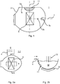
- Fig. 1 schematically shows a partially transparent top view of an example of a furnace assembly 1 for metal-making.
- the furnace assembly 1 comprises an electric arc furnace 3 having a body or furnace shell configured to receive and hold metallic material during a tap-to-tap cycle.
- the body or furnace shell is furthermore configured to receive a plurality of electrodes arranged to be lowered into the body or furnace shell to melt any metallic material contained therein.
- the electric arc furnace 3 comprises a bottom 3a having a tapping hole 3b, or alternatively or additionally a spout 3c, in order to enable tapping of the heat of metal from the body or furnace shell.
- the tapping hole 3b is arranged offset, or off-centre, relative to the centre point of the bottom 3a of the furnace shell.
- the furnace assembly 1 furthermore comprises an electromagnetic stirrer 5.
- the bottom 3a of the electric arc furnace 3 comprises a non-magnetic window, beneath which the electromagnetic stirrer 5 is configured to be installed.
- the non-magnetic window may for example comprise austenitic stainless steel, or any other kind of non-magnetic metallic material.
- the electromagnetic stirrer 5 comprises a magnetic core and coils arranged around the magnetic core, not shown.
- the coils may be configured to be connected to a respective electric phase of an AC current supply so that the electromagnetic stirrer 5 can be fed with a poly-phase low frequency AC current.
- the coils are thus configured such that when suitably fed with a respective AC current, a traveling magnetic field is generated along a stirring direction axis 9.
- the low frequency AC current through the coils generates a traveling magnetic field which penetrates the electric arc furnace bottom and thereby generates forces in the molten metal or melt. Since the magnetic field penetrates the whole depth of the melt, the melt will flow in the same direction, along the stirring direction axis 9, across the entire diameter/width of the electric arc furnace and down to the whole depth of the bath. After reaching the electric arc furnace wall the melt will flow back along the sides of the electric arc furnace.
- a central plane 7 is shown, extending through the centre point of the bottom 3a and through the centre of the tapping hole 3b, or in case of a presence of a spout 3c, through the centre of the spout 3c.
- This plane is typically a vertical plane when the furnace assembly 1 has been installed in a metal works or metal mill, for example a steel mill or an aluminium mill.
- the electromagnetic stirrer 5 is configured so that there is an angle ⁇ between the central plane 7 and the stirring direction axis 9 which intersects the central plane 7.
- the angle ⁇ is 90°.
- the angle ⁇ between the central plane 7 and the stirring direction axis 9 may be in the range of 0° and 90°.
- the angle ⁇ may be 0°, or the angle ⁇ may be more than 0° but less than 90°.
- the electromagnetic stirrer 5 would be inclined or arranged obliquely with respect to the central plane 7.
- the electromagnetic stirrer 5 may be arranged centred underneath the electric arc furnace with respect to the centre of the electric arc furnace, or it may be arranged off-set from the centre.
- the orientation of the electromagnetic stirrer relative to the central plane 7 may be adjusted, either manually or in an automated manner.
- the furnace assembly may comprise an electromagnetic stirrer position controller configured to control the orientation of the electromagnetic stirrer 5 relative to the electric arc furnace 3, and in particular relative to the central plane 7, to thereby adjust the angle ⁇ .
- the angle ⁇ may for example be adjusted or controlled based on the instantaneous amount of global stirring of the melt necessary and based on the need of vortex reduction above the tapping hole 3a, in the event that the electric arc furnace 3 has a tapping hole.
- the orientation of the electromagnetic stirrer 5 may thus be a trade-off between optimal global stirring and vortex reduction.
- the electric arc furnace 3 also has a metal-charging region 11, which is a region of the bottom 3a of the body or furnace shell where the metallic material charged continuously into the furnace shell is initially accumulated in the electric arc furnace 3.
- the metal-charging region 11 may be arranged off-centre with respect to centre of the bottom 3a, as shown in the example in Fig. 1 .
- the metal-charging region 11 may be arranged at the centre or essentially at the centre of the bottom 3a.
- the metal-charging region 11 will typically not be at bottom of the body or furnace shell, but on the surface or meniscus of the melt. In this case, the metal-charging region may be arranged centred or off-centre in a horizontal section of the electric arc furnace.
- the electromagnetic stirrer 5 is arranged so that the stirring force created by the electromagnetic stirrer 5 is directed towards the cold zone formed by the metal-charging region 11, or at an angle of up to 90° depending on the orientation of the electromagnetic stirrer 5 relative to the central plane 7. It is thereby possible to create a melt flow towards or backwards the metal-charging region 11 in the electric arc furnace 3, which greatly improves the metal-melting and temperature homogenisation compared to the use of, or without use of, porous plugs in combination with gas.
- the electromagnetic stirrer 5 may be arranged centred underneath the electric arc furnace, or it may be arranged off-centre. In the latter case, the electromagnetic stirrer may for example be arranged underneath the metal-charging area 11, with the angle ⁇ anywhere between 0° and 90° degrees relative to the central plane 7.
- the furnace assembly may comprise a power converter, typically a frequency converter, not shown, configured to control the current in the coils of the electromagnetic stirrer, to thereby control the stirring of the molten metal or melt contained in the furnace shell.
- the furnace assembly may also comprise a control system configured to control the frequency converter to thereby control the current in the electromagnetic stirrer.
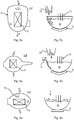
- Fig. 2a shows a partially transparent bottom view of an example of a furnace assembly 1 with flat bath operation.
- the exemplified furnace assembly 1-1 is continuously fed with metallic material from the side of the furnace shell by means of a conveyor belt 4.
- the electromagnetic stirrer 5 is arranged below the bottom of the electric arc furnace 3.
- the electromagnetic stirrer 5 shown with solid lines is depicted with an angle ⁇ that is 90° relative to the central plane 7 shown in Fig. 1 .
- the electromagnetic stirrer 5 is also shown with another orientation, with dashed lines, where the angle ⁇ is 0° relative to the central plane 7.
- the electromagnetic stirrer 5 may be configured to be oriented with any angle ⁇ between 0° and 90° or with essentially any angle ⁇ between 0° and 90°. For example, if the electromagnetic stirrer is motor-driven, not all angles may be possible to be attained and the actual orientation may be dependent upon the resolution provided by the electromagnetic stirrer position controller.
- a cross-sectional view of the furnace assembly 1-1 is shown, with the cross-section being taken at lines A-A in Fig. 2a .
- the electrodes 13 which are submerged in the melt M are also shown, as well as the metal-charging region 11.
- the metallic material may be charged continuously into furnace shell or body by means of a conveyor belt 4 moving from the side towards the electric arc furnace 3.
- Fig. 3a shows a partially transparent top view of another example of a furnace assembly 1 with flat bath operation.
- the exemplified furnace assembly 1-2 is fed with metallic material from the top to e.g. an off-centre location in the electric arc furnace 3, via a shaft 15 arranged above the electric arc furnace 3.
- the electromagnetic stirrer 5 may again be able to be oriented within 0° and 90° relative to the central plane 7 shown in Fig. 1 .
- Fig. 3b shows the furnace assembly 1-2 through the cross-section taken at lines B-B.
- Fig. 4a shows a partially transparent top view of another example of a furnace assembly 1 with flat bath operation.
- the exemplified furnace assembly 1-3 is continuously fed with metallic material from the side via a conveyer belt 4, and it is also charged from the top via a shaft 15 arranged above the electric arc furnace 3. Feeding may be provided alternatingly by means of the conveyor belt and the shaft, or simultaneously.
- the electric arc furnace has a spout for tapping the melt, but could alternative be provided with a tapping hole.
- the electromagnetic stirrer 5 may also in this case be configured to be oriented within 0° and 90° relative to the central plane 7 shown in Fig. 1 .
- Fig. 4b shows the furnace assembly 1-3 through the cross-section taken at lines C-C.
- Fig. 5a shows a partially transparent top view of another example of a furnace assembly 1 with flat bath operation.
- the exemplified furnace assembly 1-4 is continuously fed with metallic material from above the electric arc furnace 3 by means of a conveyor belt or a runner.
- the roof of the electric arc furnace 3 is provided with a through-opening 16, i.e. a feeding hole, for example the "5 th hole", for feeding metallic material into the electric arc furnace 3 by means of the conveyor belt or the runner.
- the metallic material may for example comprise or be direct reduced iron.
- the electromagnetic stirrer 5 may like previously having been described, be able to be oriented within 0° and 90° relative to the central plane 7 shown in Fig. 1 .
- Fig. 5b shows the furnace assembly 1-3 through the cross-section taken at lines D-D.
- the metallic material used for continuous feeding may for example be scrap, ferroalloys, direct reduced iron, hot briquetted iron, pig iron, hot metal, or mixing of metallic materials and oxides.
Landscapes
- Engineering & Computer Science (AREA)
- Mechanical Engineering (AREA)
- General Engineering & Computer Science (AREA)
- Physics & Mathematics (AREA)
- Electromagnetism (AREA)
- Vertical, Hearth, Or Arc Furnaces (AREA)
- Refinement Of Pig-Iron, Manufacture Of Cast Iron, And Steel Manufacture Other Than In Revolving Furnaces (AREA)
- Waste-Gas Treatment And Other Accessory Devices For Furnaces (AREA)
Priority Applications (1)
| Application Number | Priority Date | Filing Date | Title |
|---|---|---|---|
| EP21153048.0A EP3848656A1 (en) | 2017-02-10 | 2017-02-10 | Furnace assembly for a metal-making process |
Applications Claiming Priority (1)
| Application Number | Priority Date | Filing Date | Title |
|---|---|---|---|
| PCT/EP2017/052941 WO2018145754A1 (en) | 2017-02-10 | 2017-02-10 | Furnace assembly for a metal-making process |
Related Child Applications (2)
| Application Number | Title | Priority Date | Filing Date |
|---|---|---|---|
| EP21153048.0A Division EP3848656A1 (en) | 2017-02-10 | 2017-02-10 | Furnace assembly for a metal-making process |
| EP21153048.0A Division-Into EP3848656A1 (en) | 2017-02-10 | 2017-02-10 | Furnace assembly for a metal-making process |
Publications (2)
| Publication Number | Publication Date |
|---|---|
| EP3580512A1 EP3580512A1 (en) | 2019-12-18 |
| EP3580512B1 true EP3580512B1 (en) | 2021-03-31 |
Family
ID=58018098
Family Applications (2)
| Application Number | Title | Priority Date | Filing Date |
|---|---|---|---|
| EP17704737.0A Active EP3580512B1 (en) | 2017-02-10 | 2017-02-10 | Furnace assembly for a metal-making process |
| EP21153048.0A Pending EP3848656A1 (en) | 2017-02-10 | 2017-02-10 | Furnace assembly for a metal-making process |
Family Applications After (1)
| Application Number | Title | Priority Date | Filing Date |
|---|---|---|---|
| EP21153048.0A Pending EP3848656A1 (en) | 2017-02-10 | 2017-02-10 | Furnace assembly for a metal-making process |
Country Status (9)
| Country | Link |
|---|---|
| US (2) | US10921060B2 (enExample) |
| EP (2) | EP3580512B1 (enExample) |
| JP (1) | JP7026693B2 (enExample) |
| KR (2) | KR102463656B1 (enExample) |
| CN (2) | CN110312908A (enExample) |
| BR (1) | BR112019014882B1 (enExample) |
| ES (1) | ES2871782T3 (enExample) |
| RU (1) | RU2731947C1 (enExample) |
| WO (1) | WO2018145754A1 (enExample) |
Families Citing this family (4)
| Publication number | Priority date | Publication date | Assignee | Title |
|---|---|---|---|---|
| IT201900016790A1 (it) | 2019-09-19 | 2021-03-19 | Danieli Off Mecc | Metodo di agitazione di metallo liquido in un forno elettrico ad arco |
| CN116261493A (zh) * | 2020-08-04 | 2023-06-13 | 麦角灵实验室公司 | 用于熔化炉的搅拌装置和方法及熔化炉 |
| JPWO2025062841A1 (enExample) * | 2023-09-19 | 2025-03-27 | ||
| JP7637319B1 (ja) | 2023-09-19 | 2025-02-27 | Jfeスチール株式会社 | 金属原料の溶解方法 |
Citations (9)
| Publication number | Priority date | Publication date | Assignee | Title |
|---|---|---|---|---|
| US4470846A (en) | 1981-05-19 | 1984-09-11 | Alcan International Limited | Removal of alkali metals and alkaline earth metals from molten aluminum |
| JPH05332679A (ja) | 1992-06-03 | 1993-12-14 | Kawasaki Steel Corp | 直流電気炉 |
| US5346528A (en) | 1992-09-18 | 1994-09-13 | Kyoei Steel Co., Ltd. | Continuous automatic steel making method and facility |
| JPH0961065A (ja) | 1995-08-18 | 1997-03-07 | Daido Steel Co Ltd | スクラップ予熱装置付き直流アーク炉 |
| US20090031854A1 (en) | 2005-07-14 | 2009-02-05 | Techint Compagnia Tecnica Internazionale S.P.A. | Apparatus for the Combustion of Gas Exiting From a Furnace, for the Preheating of Scraps Entering the Furnace Itself and Related Process |
| SE1300434A1 (sv) | 2013-06-17 | 2013-06-20 | Abb Technology Ltd | En anordning för elektromagnetisk omrörning av smältan i en elektrisk ljusbågsugn |
| US20130211581A1 (en) | 2010-08-18 | 2013-08-15 | Tenova S.P.A | Method and control and tracking system of the charge of material transported by a continuous supply conveyor of a metallurgical furnace, particularly an electric furnace for the production of steel |
| US20140175715A1 (en) | 2011-08-29 | 2014-06-26 | Jan-Erik Eriksson | Method And Arrangement For Vortex Reduction In A Metal Making Process |
| WO2015122086A1 (ja) | 2014-02-14 | 2015-08-20 | スチールプランテック株式会社 | 原料運搬バケット、予熱装置、溶解設備、および溶解設備の操業方法 |
Family Cites Families (44)
| Publication number | Priority date | Publication date | Assignee | Title |
|---|---|---|---|---|
| CA839874A (en) | 1970-04-21 | Sixel Gustav-Adolf | Electric-arc furnace with stirrer coil | |
| US1300434A (en) | 1917-10-13 | 1919-04-15 | Allan L Mcgregor | Automobile-bumper. |
| US2513082A (en) | 1944-11-30 | 1950-06-27 | Asea Ab | Induction stirrer |
| BE522779A (enExample) | 1952-09-20 | |||
| US2767236A (en) | 1954-10-14 | 1956-10-16 | James W Williamson | Magnetic stirrer for molten metal furnaces |
| DE1271904B (de) | 1962-03-21 | 1968-07-04 | Asea Ab | Elektromagnetischer Umruehrer fuer metallurgische Zwecke |
| US3199842A (en) | 1962-04-12 | 1965-08-10 | Asea Ab | Gas-cooled electro-magnetic stirrer |
| DE1207524B (de) | 1964-07-22 | 1965-12-23 | Beteiligungs & Patentverw Gmbh | Mit Ruehrspule versehener Elektro-Lichtbogen-ofen |
| US3396228A (en) | 1965-08-02 | 1968-08-06 | Asea Ab | Electromagnetic stirrer |
| DE2362089A1 (de) | 1973-12-14 | 1975-06-26 | Degussa | Loeschbleche fuer elektrische schalter |
| SE390688B (sv) * | 1974-07-23 | 1977-01-03 | Asea Ab | Anordning vid likstromsmatade ljusbagsugnar |
| DE3309498A1 (de) | 1983-03-17 | 1984-09-20 | Leningradskoe proizvodstvennoe elektromašinostroitel'noe obedinenie "Elektrosila" imeni S.M. Kirova, Leningrad | Stator eines elektromagnetischen durchmischers |
| JPH0665950B2 (ja) | 1985-08-16 | 1994-08-24 | 石川島播磨重工業株式会社 | ア−ク炉のスクラツプ等の原料装入方法 |
| JPS6273591A (ja) * | 1985-09-27 | 1987-04-04 | 株式会社神戸製鋼所 | 炉内溶湯撹拌装置 |
| SE452991B (sv) * | 1985-12-20 | 1988-01-04 | Asea Ab | Sett och anordning for att effektivisera slagg-/badreaktioner medelst induktiv omroring |
| JPH0254711A (ja) | 1988-08-17 | 1990-02-23 | Sumitomo Metal Ind Ltd | スラグ流出防止方法 |
| US4862477A (en) | 1988-09-01 | 1989-08-29 | Manville Corporation | Apparatus and method for melting and homogenizing batch material |
| JP3333220B2 (ja) | 1991-10-25 | 2002-10-15 | 川崎製鉄株式会社 | 電気炉の炉体構造 |
| SE504400C2 (sv) | 1995-04-25 | 1997-02-03 | Asea Brown Boveri | Ugnsanläggning för smältning av metall och/eller varmhållning av smält metall |
| US5802065A (en) * | 1995-10-23 | 1998-09-01 | Kawasaki Steel Corporation | Data receiving device |
| JPH1078291A (ja) * | 1996-09-02 | 1998-03-24 | Shinko Electric Co Ltd | 溶融金属の推力発生装置 |
| IT1289001B1 (it) | 1996-10-14 | 1998-09-25 | Danieli Off Mecc | Sistema per l'agitazione elettromagnetica del metallo liquido in forni elettrici ad arco a corrente continua |
| IT1295102B1 (it) | 1997-04-21 | 1999-04-30 | Danieli Off Mecc | Sistema a forno elettrico ad arco |
| HU222124B1 (hu) | 1997-07-31 | 2003-04-28 | International Procurement, Inc. | Eljárás és berendezés metallurgiai üstben kezelt fémolvadék elektromágneses mezővel folytatott keverésére |
| RU2148291C1 (ru) | 1999-04-23 | 2000-04-27 | Христинич Роман Мирославович | Статор для электромагнитного перемешивания стали в дуговых сталеплавильных печах и сталеразливочных ковшах |
| JP2004251530A (ja) | 2003-02-20 | 2004-09-09 | Jp Steel Plantech Co | 冷鉄源のアーク溶解炉 |
| US7651656B2 (en) | 2006-07-20 | 2010-01-26 | Kenzo Takahashi | Melting furnace with agitator and agitator for melting furnace |
| JP5646138B2 (ja) | 2008-06-27 | 2014-12-24 | 高橋 謙三 | 攪拌装置付溶解炉 |
| CN101649366B (zh) | 2009-03-04 | 2011-10-05 | 贾会平 | 熔融还原炼铁的电弧炉装置 |
| DE202009004198U1 (de) | 2009-03-25 | 2010-08-12 | Ellenberger & Poensgen Gmbh | Trennschalter zur galvanischen Gleichstromunterbrechung |
| CN101876024B (zh) | 2009-04-30 | 2011-09-21 | 宝山钢铁股份有限公司 | 一种供管坯高铬含n双相不锈钢连铸小方坯的生产方法 |
| KR101420067B1 (ko) | 2010-09-14 | 2014-07-18 | 에이비비 리써치 리미티드 | 전기 아크로에서 전자기 교반하는 장치 및 방법 |
| CN102183150B (zh) | 2011-04-25 | 2013-07-03 | 中冶赛迪工程技术股份有限公司 | 用于向电炉中加入废钢的快速加料装置及其加料方法 |
| JP5620030B2 (ja) | 2011-07-18 | 2014-11-05 | エー ビー ビー リサーチ リミテッド | 熔融プロセスを制御するための方法及び制御システム |
| MX2014008174A (es) | 2012-01-03 | 2014-10-06 | Abb Research Ltd | Un metodo para fundir acero. |
| RU124956U1 (ru) | 2012-06-14 | 2013-02-20 | Открытое Акционерное Общество "Тяжпрессмаш" | Электродуговая печь постоянного тока для плавки |
| RU126810U1 (ru) | 2012-12-13 | 2013-04-10 | Игорь Михайлович Ячиков | Электродуговая печь постоянного тока |
| KR101406503B1 (ko) * | 2012-12-21 | 2014-06-13 | 주식회사 포스코 | 고정형 전기로 및 용강 제조 방법 |
| CN103886346A (zh) | 2012-12-24 | 2014-06-25 | 鸿富锦精密工业(深圳)有限公司 | 条码读写器及投递信息处理系统 |
| EP2792755B1 (en) * | 2013-04-16 | 2015-06-10 | ABB Technology Ltd | A method and a control system for controlling a melting and refining process |
| CN104707960B (zh) | 2013-12-17 | 2017-03-01 | 北京有色金属研究总院 | 一种弯月面径向强剪切电磁搅拌圆坯连铸装置和方法 |
| RU2016143525A (ru) | 2014-06-16 | 2018-07-16 | Абб Швайц Аг | Структура из немагнитной стали для процесса получения стали или алюминия |
| WO2016026530A1 (en) | 2014-08-21 | 2016-02-25 | Abb Technology Ltd | A system and a method for determining temperature of a metal melt in an electric arc furnace |
| EP3059827A1 (en) | 2015-02-20 | 2016-08-24 | ABB Technology Ltd | Switching system for breaking a current and method of performing a current breaking operation |
-
2017
- 2017-02-10 WO PCT/EP2017/052941 patent/WO2018145754A1/en not_active Ceased
- 2017-02-10 US US16/482,033 patent/US10921060B2/en active Active
- 2017-02-10 ES ES17704737T patent/ES2871782T3/es active Active
- 2017-02-10 KR KR1020207034890A patent/KR102463656B1/ko active Active
- 2017-02-10 EP EP17704737.0A patent/EP3580512B1/en active Active
- 2017-02-10 JP JP2019543351A patent/JP7026693B2/ja active Active
- 2017-02-10 EP EP21153048.0A patent/EP3848656A1/en active Pending
- 2017-02-10 CN CN201780086162.3A patent/CN110312908A/zh active Pending
- 2017-02-10 KR KR1020197024084A patent/KR20190103415A/ko not_active Ceased
- 2017-02-10 RU RU2019127045A patent/RU2731947C1/ru active
- 2017-02-10 BR BR112019014882-5A patent/BR112019014882B1/pt active IP Right Grant
- 2017-02-10 CN CN202311292185.3A patent/CN117367098A/zh active Pending
-
2021
- 2021-01-07 US US17/143,415 patent/US11543182B2/en active Active
Patent Citations (9)
| Publication number | Priority date | Publication date | Assignee | Title |
|---|---|---|---|---|
| US4470846A (en) | 1981-05-19 | 1984-09-11 | Alcan International Limited | Removal of alkali metals and alkaline earth metals from molten aluminum |
| JPH05332679A (ja) | 1992-06-03 | 1993-12-14 | Kawasaki Steel Corp | 直流電気炉 |
| US5346528A (en) | 1992-09-18 | 1994-09-13 | Kyoei Steel Co., Ltd. | Continuous automatic steel making method and facility |
| JPH0961065A (ja) | 1995-08-18 | 1997-03-07 | Daido Steel Co Ltd | スクラップ予熱装置付き直流アーク炉 |
| US20090031854A1 (en) | 2005-07-14 | 2009-02-05 | Techint Compagnia Tecnica Internazionale S.P.A. | Apparatus for the Combustion of Gas Exiting From a Furnace, for the Preheating of Scraps Entering the Furnace Itself and Related Process |
| US20130211581A1 (en) | 2010-08-18 | 2013-08-15 | Tenova S.P.A | Method and control and tracking system of the charge of material transported by a continuous supply conveyor of a metallurgical furnace, particularly an electric furnace for the production of steel |
| US20140175715A1 (en) | 2011-08-29 | 2014-06-26 | Jan-Erik Eriksson | Method And Arrangement For Vortex Reduction In A Metal Making Process |
| SE1300434A1 (sv) | 2013-06-17 | 2013-06-20 | Abb Technology Ltd | En anordning för elektromagnetisk omrörning av smältan i en elektrisk ljusbågsugn |
| WO2015122086A1 (ja) | 2014-02-14 | 2015-08-20 | スチールプランテック株式会社 | 原料運搬バケット、予熱装置、溶解設備、および溶解設備の操業方法 |
Also Published As
| Publication number | Publication date |
|---|---|
| EP3580512A1 (en) | 2019-12-18 |
| KR20200139276A (ko) | 2020-12-11 |
| US10921060B2 (en) | 2021-02-16 |
| RU2731947C1 (ru) | 2020-09-09 |
| CN110312908A (zh) | 2019-10-08 |
| EP3848656A1 (en) | 2021-07-14 |
| US11543182B2 (en) | 2023-01-03 |
| US20190390908A1 (en) | 2019-12-26 |
| BR112019014882B1 (pt) | 2022-03-03 |
| BR112019014882A2 (pt) | 2020-03-03 |
| JP2020505579A (ja) | 2020-02-20 |
| WO2018145754A1 (en) | 2018-08-16 |
| CN117367098A (zh) | 2024-01-09 |
| KR20190103415A (ko) | 2019-09-04 |
| KR102463656B1 (ko) | 2022-11-03 |
| ES2871782T3 (es) | 2021-11-02 |
| US20210164731A1 (en) | 2021-06-03 |
| JP7026693B2 (ja) | 2022-02-28 |
Similar Documents
| Publication | Publication Date | Title |
|---|---|---|
| US11543182B2 (en) | Furnace assembly for a metal-making process | |
| US6473446B2 (en) | Electric furnace for steel making | |
| US7011136B2 (en) | Method and apparatus for melting metals | |
| US20170280519A1 (en) | Inert gas blanketing of electrodes in an electric arc furnace | |
| EP4192638B1 (en) | Agitation device and method for melting furnace and melting furnace | |
| EP4031823B1 (en) | Method of stirring liquid metal in an electric arc furnace | |
| Mathur et al. | Praxair CoJet™ technology–Principles and actual results from recent installations | |
| KR20210151968A (ko) | 크롬 함유 용철의 제조 방법 | |
| Teng et al. | ArcSave®–Innovative solution for higher productivity and lower cost in the EAF | |
| Dutta et al. | Electric Furnace Processes | |
| RU126810U1 (ru) | Электродуговая печь постоянного тока | |
| WO2004036131A1 (en) | Electric furnace for steel making | |
| Teng et al. | Process improvement with EMS | |
| Grasselli et al. | Consteerrer™ technology: Getting the most out of the electric steelmaking process | |
| Teng et al. | THE EFFECT OF ARCSAVE TM ON THE EAF PROCESS WITH ECCENTRIC BOTTOM TAPPING | |
| WO2025062841A1 (ja) | 電気炉設備 | |
| Conejo | Stirring in the EAF | |
| KR20260070212A (ko) | 전기로 설비 | |
| Bode et al. | Coreless induction in micro mills | |
| De Jong et al. | New TiO2 slag plant for CYMCO using 30MW DC furnace | |
| JP2000088462A (ja) | 溶融金属用炉 | |
| Mironov et al. | Effect of electrodynamic phenomena in arc furnaces on the meniscus formation in a liquid metal | |
| Kuhn | Optimising costs and productivity by avoiding hot spots and arc radiation in the electric arc furnace. | |
| Zhang et al. | Electric Arc Furnace Operation with Electromagnetic Stirring and Hot Heel | |
| McManus | Stony Creek Steel: a Steelmaking Showcase |
Legal Events
| Date | Code | Title | Description |
|---|---|---|---|
| STAA | Information on the status of an ep patent application or granted ep patent |
Free format text: STATUS: UNKNOWN |
|
| STAA | Information on the status of an ep patent application or granted ep patent |
Free format text: STATUS: THE INTERNATIONAL PUBLICATION HAS BEEN MADE |
|
| TPAC | Observations filed by third parties |
Free format text: ORIGINAL CODE: EPIDOSNTIPA |
|
| PUAI | Public reference made under article 153(3) epc to a published international application that has entered the european phase |
Free format text: ORIGINAL CODE: 0009012 |
|
| STAA | Information on the status of an ep patent application or granted ep patent |
Free format text: STATUS: REQUEST FOR EXAMINATION WAS MADE |
|
| 17P | Request for examination filed |
Effective date: 20190904 |
|
| AK | Designated contracting states |
Kind code of ref document: A1 Designated state(s): AL AT BE BG CH CY CZ DE DK EE ES FI FR GB GR HR HU IE IS IT LI LT LU LV MC MK MT NL NO PL PT RO RS SE SI SK SM TR |
|
| AX | Request for extension of the european patent |
Extension state: BA ME |
|
| DAV | Request for validation of the european patent (deleted) | ||
| DAX | Request for extension of the european patent (deleted) | ||
| GRAP | Despatch of communication of intention to grant a patent |
Free format text: ORIGINAL CODE: EPIDOSNIGR1 |
|
| STAA | Information on the status of an ep patent application or granted ep patent |
Free format text: STATUS: GRANT OF PATENT IS INTENDED |
|
| TPAC | Observations filed by third parties |
Free format text: ORIGINAL CODE: EPIDOSNTIPA |
|
| INTG | Intention to grant announced |
Effective date: 20201001 |
|
| GRAS | Grant fee paid |
Free format text: ORIGINAL CODE: EPIDOSNIGR3 |
|
| GRAA | (expected) grant |
Free format text: ORIGINAL CODE: 0009210 |
|
| STAA | Information on the status of an ep patent application or granted ep patent |
Free format text: STATUS: THE PATENT HAS BEEN GRANTED |
|
| AK | Designated contracting states |
Kind code of ref document: B1 Designated state(s): AL AT BE BG CH CY CZ DE DK EE ES FI FR GB GR HR HU IE IS IT LI LT LU LV MC MK MT NL NO PL PT RO RS SE SI SK SM TR |
|
| REG | Reference to a national code |
Ref country code: GB Ref legal event code: FG4D Ref country code: CH Ref legal event code: EP |
|
| RAP4 | Party data changed (patent owner data changed or rights of a patent transferred) |
Owner name: ABB SCHWEIZ AG Owner name: TENOVA S.P.A. |
|
| REG | Reference to a national code |
Ref country code: AT Ref legal event code: REF Ref document number: 1377386 Country of ref document: AT Kind code of ref document: T Effective date: 20210415 |
|
| REG | Reference to a national code |
Ref country code: DE Ref legal event code: R096 Ref document number: 602017035621 Country of ref document: DE |
|
| REG | Reference to a national code |
Ref country code: IE Ref legal event code: FG4D |
|
| REG | Reference to a national code |
Ref country code: NL Ref legal event code: FP |
|
| REG | Reference to a national code |
Ref country code: LT Ref legal event code: MG9D |
|
| PG25 | Lapsed in a contracting state [announced via postgrant information from national office to epo] |
Ref country code: BG Free format text: LAPSE BECAUSE OF FAILURE TO SUBMIT A TRANSLATION OF THE DESCRIPTION OR TO PAY THE FEE WITHIN THE PRESCRIBED TIME-LIMIT Effective date: 20210630 Ref country code: NO Free format text: LAPSE BECAUSE OF FAILURE TO SUBMIT A TRANSLATION OF THE DESCRIPTION OR TO PAY THE FEE WITHIN THE PRESCRIBED TIME-LIMIT Effective date: 20210630 Ref country code: HR Free format text: LAPSE BECAUSE OF FAILURE TO SUBMIT A TRANSLATION OF THE DESCRIPTION OR TO PAY THE FEE WITHIN THE PRESCRIBED TIME-LIMIT Effective date: 20210331 Ref country code: FI Free format text: LAPSE BECAUSE OF FAILURE TO SUBMIT A TRANSLATION OF THE DESCRIPTION OR TO PAY THE FEE WITHIN THE PRESCRIBED TIME-LIMIT Effective date: 20210331 |
|
| PG25 | Lapsed in a contracting state [announced via postgrant information from national office to epo] |
Ref country code: LV Free format text: LAPSE BECAUSE OF FAILURE TO SUBMIT A TRANSLATION OF THE DESCRIPTION OR TO PAY THE FEE WITHIN THE PRESCRIBED TIME-LIMIT Effective date: 20210331 Ref country code: RS Free format text: LAPSE BECAUSE OF FAILURE TO SUBMIT A TRANSLATION OF THE DESCRIPTION OR TO PAY THE FEE WITHIN THE PRESCRIBED TIME-LIMIT Effective date: 20210331 Ref country code: SE Free format text: LAPSE BECAUSE OF FAILURE TO SUBMIT A TRANSLATION OF THE DESCRIPTION OR TO PAY THE FEE WITHIN THE PRESCRIBED TIME-LIMIT Effective date: 20210331 |
|
| PG25 | Lapsed in a contracting state [announced via postgrant information from national office to epo] |
Ref country code: LT Free format text: LAPSE BECAUSE OF FAILURE TO SUBMIT A TRANSLATION OF THE DESCRIPTION OR TO PAY THE FEE WITHIN THE PRESCRIBED TIME-LIMIT Effective date: 20210331 Ref country code: CZ Free format text: LAPSE BECAUSE OF FAILURE TO SUBMIT A TRANSLATION OF THE DESCRIPTION OR TO PAY THE FEE WITHIN THE PRESCRIBED TIME-LIMIT Effective date: 20210331 Ref country code: EE Free format text: LAPSE BECAUSE OF FAILURE TO SUBMIT A TRANSLATION OF THE DESCRIPTION OR TO PAY THE FEE WITHIN THE PRESCRIBED TIME-LIMIT Effective date: 20210331 Ref country code: SM Free format text: LAPSE BECAUSE OF FAILURE TO SUBMIT A TRANSLATION OF THE DESCRIPTION OR TO PAY THE FEE WITHIN THE PRESCRIBED TIME-LIMIT Effective date: 20210331 |
|
| REG | Reference to a national code |
Ref country code: ES Ref legal event code: FG2A Ref document number: 2871782 Country of ref document: ES Kind code of ref document: T3 Effective date: 20211102 |
|
| PG25 | Lapsed in a contracting state [announced via postgrant information from national office to epo] |
Ref country code: SK Free format text: LAPSE BECAUSE OF FAILURE TO SUBMIT A TRANSLATION OF THE DESCRIPTION OR TO PAY THE FEE WITHIN THE PRESCRIBED TIME-LIMIT Effective date: 20210331 Ref country code: RO Free format text: LAPSE BECAUSE OF FAILURE TO SUBMIT A TRANSLATION OF THE DESCRIPTION OR TO PAY THE FEE WITHIN THE PRESCRIBED TIME-LIMIT Effective date: 20210331 Ref country code: PL Free format text: LAPSE BECAUSE OF FAILURE TO SUBMIT A TRANSLATION OF THE DESCRIPTION OR TO PAY THE FEE WITHIN THE PRESCRIBED TIME-LIMIT Effective date: 20210331 Ref country code: PT Free format text: LAPSE BECAUSE OF FAILURE TO SUBMIT A TRANSLATION OF THE DESCRIPTION OR TO PAY THE FEE WITHIN THE PRESCRIBED TIME-LIMIT Effective date: 20210802 Ref country code: IS Free format text: LAPSE BECAUSE OF FAILURE TO SUBMIT A TRANSLATION OF THE DESCRIPTION OR TO PAY THE FEE WITHIN THE PRESCRIBED TIME-LIMIT Effective date: 20210731 |
|
| REG | Reference to a national code |
Ref country code: AT Ref legal event code: UEP Ref document number: 1377386 Country of ref document: AT Kind code of ref document: T Effective date: 20210331 |
|
| REG | Reference to a national code |
Ref country code: DE Ref legal event code: R026 Ref document number: 602017035621 Country of ref document: DE |
|
| PLBI | Opposition filed |
Free format text: ORIGINAL CODE: 0009260 |
|
| PLAX | Notice of opposition and request to file observation + time limit sent |
Free format text: ORIGINAL CODE: EPIDOSNOBS2 |
|
| PG25 | Lapsed in a contracting state [announced via postgrant information from national office to epo] |
Ref country code: AL Free format text: LAPSE BECAUSE OF FAILURE TO SUBMIT A TRANSLATION OF THE DESCRIPTION OR TO PAY THE FEE WITHIN THE PRESCRIBED TIME-LIMIT Effective date: 20210331 Ref country code: DK Free format text: LAPSE BECAUSE OF FAILURE TO SUBMIT A TRANSLATION OF THE DESCRIPTION OR TO PAY THE FEE WITHIN THE PRESCRIBED TIME-LIMIT Effective date: 20210331 |
|
| 26 | Opposition filed |
Opponent name: DANIELI & C. OFFICINE MECCANICHE SPA Effective date: 20211223 |
|
| PLBB | Reply of patent proprietor to notice(s) of opposition received |
Free format text: ORIGINAL CODE: EPIDOSNOBS3 |
|
| PG25 | Lapsed in a contracting state [announced via postgrant information from national office to epo] |
Ref country code: IS Free format text: LAPSE BECAUSE OF FAILURE TO SUBMIT A TRANSLATION OF THE DESCRIPTION OR TO PAY THE FEE WITHIN THE PRESCRIBED TIME-LIMIT Effective date: 20210731 |
|
| PG25 | Lapsed in a contracting state [announced via postgrant information from national office to epo] |
Ref country code: MC Free format text: LAPSE BECAUSE OF FAILURE TO SUBMIT A TRANSLATION OF THE DESCRIPTION OR TO PAY THE FEE WITHIN THE PRESCRIBED TIME-LIMIT Effective date: 20210331 |
|
| PG25 | Lapsed in a contracting state [announced via postgrant information from national office to epo] |
Ref country code: IE Free format text: LAPSE BECAUSE OF NON-PAYMENT OF DUE FEES Effective date: 20220210 |
|
| APAH | Appeal reference modified |
Free format text: ORIGINAL CODE: EPIDOSCREFNO |
|
| APBM | Appeal reference recorded |
Free format text: ORIGINAL CODE: EPIDOSNREFNO |
|
| APBP | Date of receipt of notice of appeal recorded |
Free format text: ORIGINAL CODE: EPIDOSNNOA2O |
|
| APBM | Appeal reference recorded |
Free format text: ORIGINAL CODE: EPIDOSNREFNO |
|
| APBP | Date of receipt of notice of appeal recorded |
Free format text: ORIGINAL CODE: EPIDOSNNOA2O |
|
| APBQ | Date of receipt of statement of grounds of appeal recorded |
Free format text: ORIGINAL CODE: EPIDOSNNOA3O |
|
| PG25 | Lapsed in a contracting state [announced via postgrant information from national office to epo] |
Ref country code: MK Free format text: LAPSE BECAUSE OF FAILURE TO SUBMIT A TRANSLATION OF THE DESCRIPTION OR TO PAY THE FEE WITHIN THE PRESCRIBED TIME-LIMIT Effective date: 20210331 Ref country code: CY Free format text: LAPSE BECAUSE OF FAILURE TO SUBMIT A TRANSLATION OF THE DESCRIPTION OR TO PAY THE FEE WITHIN THE PRESCRIBED TIME-LIMIT Effective date: 20210331 |
|
| PG25 | Lapsed in a contracting state [announced via postgrant information from national office to epo] |
Ref country code: HU Free format text: LAPSE BECAUSE OF FAILURE TO SUBMIT A TRANSLATION OF THE DESCRIPTION OR TO PAY THE FEE WITHIN THE PRESCRIBED TIME-LIMIT; INVALID AB INITIO Effective date: 20170210 |
|
| PG25 | Lapsed in a contracting state [announced via postgrant information from national office to epo] |
Ref country code: MT Free format text: LAPSE BECAUSE OF FAILURE TO SUBMIT A TRANSLATION OF THE DESCRIPTION OR TO PAY THE FEE WITHIN THE PRESCRIBED TIME-LIMIT Effective date: 20210331 |
|
| PG25 | Lapsed in a contracting state [announced via postgrant information from national office to epo] |
Ref country code: GR Free format text: LAPSE BECAUSE OF NON-PAYMENT OF DUE FEES Effective date: 20210331 |
|
| PG25 | Lapsed in a contracting state [announced via postgrant information from national office to epo] |
Ref country code: GR Free format text: LAPSE BECAUSE OF NON-PAYMENT OF DUE FEES Effective date: 20210331 |
|
| PGFP | Annual fee paid to national office [announced via postgrant information from national office to epo] |
Ref country code: ES Payment date: 20250331 Year of fee payment: 9 |
|
| APBU | Appeal procedure closed |
Free format text: ORIGINAL CODE: EPIDOSNNOA9O |
|
| REG | Reference to a national code |
Ref country code: CH Ref legal event code: U11 Free format text: ST27 STATUS EVENT CODE: U-0-0-U10-U11 (AS PROVIDED BY THE NATIONAL OFFICE) Effective date: 20260301 |
|
| PGFP | Annual fee paid to national office [announced via postgrant information from national office to epo] |
Ref country code: LU Payment date: 20260218 Year of fee payment: 10 Ref country code: NL Payment date: 20260218 Year of fee payment: 10 |
|
| PGFP | Annual fee paid to national office [announced via postgrant information from national office to epo] |
Ref country code: GB Payment date: 20260219 Year of fee payment: 10 |
|
| PGFP | Annual fee paid to national office [announced via postgrant information from national office to epo] |
Ref country code: DE Payment date: 20260218 Year of fee payment: 10 |
|
| PGFP | Annual fee paid to national office [announced via postgrant information from national office to epo] |
Ref country code: AT Payment date: 20260219 Year of fee payment: 10 |
|
| PGFP | Annual fee paid to national office [announced via postgrant information from national office to epo] |
Ref country code: IT Payment date: 20260224 Year of fee payment: 10 Ref country code: BE Payment date: 20260218 Year of fee payment: 10 |
|
| PGFP | Annual fee paid to national office [announced via postgrant information from national office to epo] |
Ref country code: FR Payment date: 20260218 Year of fee payment: 10 |
|
| PGFP | Annual fee paid to national office [announced via postgrant information from national office to epo] |
Ref country code: TR Payment date: 20260204 Year of fee payment: 10 |
|
| PGFP | Annual fee paid to national office [announced via postgrant information from national office to epo] |
Ref country code: CH Payment date: 20260301 Year of fee payment: 10 |
|
| PUAH | Patent maintained in amended form |
Free format text: ORIGINAL CODE: 0009272 |
|
| STAA | Information on the status of an ep patent application or granted ep patent |
Free format text: STATUS: PATENT MAINTAINED AS AMENDED |
|
| REG | Reference to a national code |
Ref country code: CH Ref legal event code: M12 Free format text: ST27 STATUS EVENT CODE: U-0-0-M10-M12 (AS PROVIDED BY THE NATIONAL OFFICE) Effective date: 20260430 |