EP3579903B1 - Spülsystem - Google Patents
Spülsystem Download PDFInfo
- Publication number
- EP3579903B1 EP3579903B1 EP18701009.5A EP18701009A EP3579903B1 EP 3579903 B1 EP3579903 B1 EP 3579903B1 EP 18701009 A EP18701009 A EP 18701009A EP 3579903 B1 EP3579903 B1 EP 3579903B1
- Authority
- EP
- European Patent Office
- Prior art keywords
- pump
- supply line
- catheter
- support element
- discharge line
- Prior art date
- Legal status (The legal status is an assumption and is not a legal conclusion. Google has not performed a legal analysis and makes no representation as to the accuracy of the status listed.)
- Active
Links
- 238000011010 flushing procedure Methods 0.000 title claims description 48
- 239000012530 fluid Substances 0.000 claims description 54
- 230000002572 peristaltic effect Effects 0.000 claims description 12
- 238000003780 insertion Methods 0.000 claims description 5
- 230000037431 insertion Effects 0.000 claims description 5
- 230000036316 preload Effects 0.000 claims 1
- 210000000709 aorta Anatomy 0.000 description 4
- 239000008280 blood Substances 0.000 description 4
- 210000004369 blood Anatomy 0.000 description 4
- 238000005086 pumping Methods 0.000 description 4
- 239000012528 membrane Substances 0.000 description 3
- 230000002792 vascular Effects 0.000 description 3
- 238000009530 blood pressure measurement Methods 0.000 description 2
- 238000013461 design Methods 0.000 description 2
- 238000001514 detection method Methods 0.000 description 2
- 238000007599 discharging Methods 0.000 description 2
- 210000001105 femoral artery Anatomy 0.000 description 2
- 238000005259 measurement Methods 0.000 description 2
- WQZGKKKJIJFFOK-GASJEMHNSA-N Glucose Natural products OC[C@H]1OC(O)[C@H](O)[C@@H](O)[C@@H]1O WQZGKKKJIJFFOK-GASJEMHNSA-N 0.000 description 1
- HTTJABKRGRZYRN-UHFFFAOYSA-N Heparin Chemical compound OC1C(NC(=O)C)C(O)OC(COS(O)(=O)=O)C1OC1C(OS(O)(=O)=O)C(O)C(OC2C(C(OS(O)(=O)=O)C(OC3C(C(O)C(O)C(O3)C(O)=O)OS(O)(=O)=O)C(CO)O2)NS(O)(=O)=O)C(C(O)=O)O1 HTTJABKRGRZYRN-UHFFFAOYSA-N 0.000 description 1
- 241000124008 Mammalia Species 0.000 description 1
- 210000002376 aorta thoracic Anatomy 0.000 description 1
- 230000000747 cardiac effect Effects 0.000 description 1
- 230000006835 compression Effects 0.000 description 1
- 238000007906 compression Methods 0.000 description 1
- 238000010276 construction Methods 0.000 description 1
- 230000008878 coupling Effects 0.000 description 1
- 238000010168 coupling process Methods 0.000 description 1
- 238000005859 coupling reaction Methods 0.000 description 1
- 238000011161 development Methods 0.000 description 1
- 238000004851 dishwashing Methods 0.000 description 1
- 238000006073 displacement reaction Methods 0.000 description 1
- 239000008103 glucose Substances 0.000 description 1
- 210000004013 groin Anatomy 0.000 description 1
- 229960002897 heparin Drugs 0.000 description 1
- 229920000669 heparin Polymers 0.000 description 1
- 238000001746 injection moulding Methods 0.000 description 1
- 230000002262 irrigation Effects 0.000 description 1
- 238000003973 irrigation Methods 0.000 description 1
- 239000007788 liquid Substances 0.000 description 1
- 239000000314 lubricant Substances 0.000 description 1
- 238000000034 method Methods 0.000 description 1
- 238000012544 monitoring process Methods 0.000 description 1
- 230000003287 optical effect Effects 0.000 description 1
- 229920001296 polysiloxane Polymers 0.000 description 1
- 230000002000 scavenging effect Effects 0.000 description 1
- 239000000243 solution Substances 0.000 description 1
Images


Classifications
-
- A—HUMAN NECESSITIES
- A61—MEDICAL OR VETERINARY SCIENCE; HYGIENE
- A61M—DEVICES FOR INTRODUCING MEDIA INTO, OR ONTO, THE BODY; DEVICES FOR TRANSDUCING BODY MEDIA OR FOR TAKING MEDIA FROM THE BODY; DEVICES FOR PRODUCING OR ENDING SLEEP OR STUPOR
- A61M25/00—Catheters; Hollow probes
-
- A—HUMAN NECESSITIES
- A61—MEDICAL OR VETERINARY SCIENCE; HYGIENE
- A61M—DEVICES FOR INTRODUCING MEDIA INTO, OR ONTO, THE BODY; DEVICES FOR TRANSDUCING BODY MEDIA OR FOR TAKING MEDIA FROM THE BODY; DEVICES FOR PRODUCING OR ENDING SLEEP OR STUPOR
- A61M5/00—Devices for bringing media into the body in a subcutaneous, intra-vascular or intramuscular way; Accessories therefor, e.g. filling or cleaning devices, arm-rests
- A61M5/14—Infusion devices, e.g. infusing by gravity; Blood infusion; Accessories therefor
- A61M5/142—Pressure infusion, e.g. using pumps
- A61M5/14212—Pumping with an aspiration and an expulsion action
-
- A—HUMAN NECESSITIES
- A61—MEDICAL OR VETERINARY SCIENCE; HYGIENE
- A61M—DEVICES FOR INTRODUCING MEDIA INTO, OR ONTO, THE BODY; DEVICES FOR TRANSDUCING BODY MEDIA OR FOR TAKING MEDIA FROM THE BODY; DEVICES FOR PRODUCING OR ENDING SLEEP OR STUPOR
- A61M60/00—Blood pumps; Devices for mechanical circulatory actuation; Balloon pumps for circulatory assistance
- A61M60/10—Location thereof with respect to the patient's body
- A61M60/122—Implantable pumps or pumping devices, i.e. the blood being pumped inside the patient's body
- A61M60/126—Implantable pumps or pumping devices, i.e. the blood being pumped inside the patient's body implantable via, into, inside, in line, branching on, or around a blood vessel
- A61M60/13—Implantable pumps or pumping devices, i.e. the blood being pumped inside the patient's body implantable via, into, inside, in line, branching on, or around a blood vessel by means of a catheter allowing explantation, e.g. catheter pumps temporarily introduced via the vascular system
-
- A—HUMAN NECESSITIES
- A61—MEDICAL OR VETERINARY SCIENCE; HYGIENE
- A61M—DEVICES FOR INTRODUCING MEDIA INTO, OR ONTO, THE BODY; DEVICES FOR TRANSDUCING BODY MEDIA OR FOR TAKING MEDIA FROM THE BODY; DEVICES FOR PRODUCING OR ENDING SLEEP OR STUPOR
- A61M60/00—Blood pumps; Devices for mechanical circulatory actuation; Balloon pumps for circulatory assistance
- A61M60/20—Type thereof
- A61M60/205—Non-positive displacement blood pumps
- A61M60/216—Non-positive displacement blood pumps including a rotating member acting on the blood, e.g. impeller
- A61M60/226—Non-positive displacement blood pumps including a rotating member acting on the blood, e.g. impeller the blood flow through the rotating member having mainly radial components
-
- A—HUMAN NECESSITIES
- A61—MEDICAL OR VETERINARY SCIENCE; HYGIENE
- A61M—DEVICES FOR INTRODUCING MEDIA INTO, OR ONTO, THE BODY; DEVICES FOR TRANSDUCING BODY MEDIA OR FOR TAKING MEDIA FROM THE BODY; DEVICES FOR PRODUCING OR ENDING SLEEP OR STUPOR
- A61M60/00—Blood pumps; Devices for mechanical circulatory actuation; Balloon pumps for circulatory assistance
- A61M60/40—Details relating to driving
- A61M60/403—Details relating to driving for non-positive displacement blood pumps
- A61M60/408—Details relating to driving for non-positive displacement blood pumps the force acting on the blood contacting member being mechanical, e.g. transmitted by a shaft or cable
-
- A—HUMAN NECESSITIES
- A61—MEDICAL OR VETERINARY SCIENCE; HYGIENE
- A61M—DEVICES FOR INTRODUCING MEDIA INTO, OR ONTO, THE BODY; DEVICES FOR TRANSDUCING BODY MEDIA OR FOR TAKING MEDIA FROM THE BODY; DEVICES FOR PRODUCING OR ENDING SLEEP OR STUPOR
- A61M60/00—Blood pumps; Devices for mechanical circulatory actuation; Balloon pumps for circulatory assistance
- A61M60/50—Details relating to control
- A61M60/508—Electronic control means, e.g. for feedback regulation
- A61M60/538—Regulation using real-time blood pump operational parameter data, e.g. motor current
- A61M60/554—Regulation using real-time blood pump operational parameter data, e.g. motor current of blood pressure
-
- A—HUMAN NECESSITIES
- A61—MEDICAL OR VETERINARY SCIENCE; HYGIENE
- A61M—DEVICES FOR INTRODUCING MEDIA INTO, OR ONTO, THE BODY; DEVICES FOR TRANSDUCING BODY MEDIA OR FOR TAKING MEDIA FROM THE BODY; DEVICES FOR PRODUCING OR ENDING SLEEP OR STUPOR
- A61M60/00—Blood pumps; Devices for mechanical circulatory actuation; Balloon pumps for circulatory assistance
- A61M60/80—Constructional details other than related to driving
- A61M60/802—Constructional details other than related to driving of non-positive displacement blood pumps
- A61M60/804—Impellers
- A61M60/806—Vanes or blades
- A61M60/808—Vanes or blades specially adapted for deformable impellers, e.g. expandable impellers
-
- B—PERFORMING OPERATIONS; TRANSPORTING
- B08—CLEANING
- B08B—CLEANING IN GENERAL; PREVENTION OF FOULING IN GENERAL
- B08B9/00—Cleaning hollow articles by methods or apparatus specially adapted thereto
- B08B9/02—Cleaning pipes or tubes or systems of pipes or tubes
- B08B9/027—Cleaning the internal surfaces; Removal of blockages
- B08B9/032—Cleaning the internal surfaces; Removal of blockages by the mechanical action of a moving fluid, e.g. by flushing
- B08B9/0321—Cleaning the internal surfaces; Removal of blockages by the mechanical action of a moving fluid, e.g. by flushing using pressurised, pulsating or purging fluid
-
- F—MECHANICAL ENGINEERING; LIGHTING; HEATING; WEAPONS; BLASTING
- F04—POSITIVE - DISPLACEMENT MACHINES FOR LIQUIDS; PUMPS FOR LIQUIDS OR ELASTIC FLUIDS
- F04B—POSITIVE-DISPLACEMENT MACHINES FOR LIQUIDS; PUMPS
- F04B43/00—Machines, pumps, or pumping installations having flexible working members
- F04B43/12—Machines, pumps, or pumping installations having flexible working members having peristaltic action
- F04B43/1223—Machines, pumps, or pumping installations having flexible working members having peristaltic action the actuating elements, e.g. rollers, moving in a straight line during squeezing
-
- A—HUMAN NECESSITIES
- A61—MEDICAL OR VETERINARY SCIENCE; HYGIENE
- A61M—DEVICES FOR INTRODUCING MEDIA INTO, OR ONTO, THE BODY; DEVICES FOR TRANSDUCING BODY MEDIA OR FOR TAKING MEDIA FROM THE BODY; DEVICES FOR PRODUCING OR ENDING SLEEP OR STUPOR
- A61M25/00—Catheters; Hollow probes
- A61M2025/0019—Cleaning catheters or the like, e.g. for reuse of the device, for avoiding replacement
-
- A—HUMAN NECESSITIES
- A61—MEDICAL OR VETERINARY SCIENCE; HYGIENE
- A61M—DEVICES FOR INTRODUCING MEDIA INTO, OR ONTO, THE BODY; DEVICES FOR TRANSDUCING BODY MEDIA OR FOR TAKING MEDIA FROM THE BODY; DEVICES FOR PRODUCING OR ENDING SLEEP OR STUPOR
- A61M2205/00—General characteristics of the apparatus
- A61M2205/50—General characteristics of the apparatus with microprocessors or computers
- A61M2205/502—User interfaces, e.g. screens or keyboards
-
- A—HUMAN NECESSITIES
- A61—MEDICAL OR VETERINARY SCIENCE; HYGIENE
- A61M—DEVICES FOR INTRODUCING MEDIA INTO, OR ONTO, THE BODY; DEVICES FOR TRANSDUCING BODY MEDIA OR FOR TAKING MEDIA FROM THE BODY; DEVICES FOR PRODUCING OR ENDING SLEEP OR STUPOR
- A61M2209/00—Ancillary equipment
- A61M2209/10—Equipment for cleaning
Definitions
- the invention relates to a flushing system for a catheter, in particular for a catheter of a catheter pump, comprising a supply line with a pump section, a discharge line with a pump section and a pump.
- the invention also relates to an associated support element, an associated console and a catheter pump system.
- a catheter pump is, for example, from EP 2 288 392 B1 famous.
- the catheter pump has a drive unit and a catheter.
- the catheter comprises a pump head for insertion in particular into the arterial vascular system such as the aorta or the heart, and a rotatably arranged rotor shaft for driving an expandable conveying element provided on the pump head.
- a rotor with fold-out propellers, which is provided at the proximal end of the catheter, can be used as the rotating conveying element.
- Catheter pumps are used as a temporary circulatory support system in the arterial vascular system, such as the aorta, of patients, particularly when the natural heart is unable to supply the body with adequately oxygenated blood.
- the conveying element and the rotor shaft are operated at comparatively high speeds in the range from 7000 to 15000 revolutions per minute and in particular in the range from 10000 to 13000 revolutions.
- a flushing system is connected to the catheter.
- a flushing system is, for example, from WO 2014/164136 A1 previously known.
- a supply line for supplying rinsing fluid and a discharge line for discharging rinsing fluid are connected to the catheter.
- a rotary peristaltic pump is provided for the feed line and the discharge line in order to achieve fluid conveyance in the feed and discharge lines.
- the two pumps are controlled separately in this case in order to convey a corresponding amount of fluid into the catheter or to remove it from the catheter and to achieve a desired ratio of fluid supplied to fluid removed.
- this scavenging system is expensive and complex in construction because two pumps must be provided, and on the other hand it is complex to control or program because both pumps have to be matched to one another.
- a peristaltic pump which has a supply line and a discharge line, each with pump sections, it being possible for the pump sections to have different diameters.
- a flushing system having the features of claim 1. Accordingly, it is provided that the diameter of the pump section of the discharge line is smaller than the diameter of the pump section of the supply line. Furthermore, it is provided that the pump interacts with the pump section of the supply line for supplying rinsing fluid to the catheter. Finally, it is provided that the pump interacts with the pump section of the discharge line for discharging flushing fluid from the catheter.
- a carrier element is provided, to which the supply line and the discharge line are fastened.
- the carrier element can be used in a particularly simple manner to provide an operative connection between the feed and discharge lines and the pump, in that the carrier element is suitably attached in the pump area in such a way that the pump sections of the feed and discharge lines can interact with the pump.
- the carrier element extends along a main extension plane.
- the feed and discharge lines extend through the carrier element in this main extension plane.
- the carrier element is consequently of particularly compact design and can be connected to a linear peristaltic pump in a particularly simple manner
- the carrier element has an opening, with the pump sections of the supply and discharge lines extending along the opening and thus bridging it. It is conceivable that the fingers of the linear peristaltic pump engage in the opening and thus interact with the pump sections that bridge the opening.
- the catheter can, as explained above, be the catheter of a catheter pump. On the other hand, it can also be a wide variety of other catheters, such as a catheter of a stent delivery system.
- the pump is designed as a linear peristaltic pump.
- the pump has a camshaft with a number of lobes, each lobe being coupled for movement with a respective finger.
- Each finger interacts with the supply line and the drain line to convey fluid.
- the fingers sequentially squeeze the supply line and the discharge line to create fluid flow. Consequently, with the movement of the fingers, the squeezed pumping section area also migrates, so that a fluid flow is achieved.
- fluid can be supplied to the catheter or fluid can be removed from the catheter by means of only one pump.
- the supply line or the discharge line has an arcuate section, with the section running through the carrier element so that the supply line or discharge line is on the same side of the Carrier element is guided into the carrier element or out of the carrier element.
- the feed and/or discharge line can consequently be fed to the carrier element on one side of the carrier element and led out of the carrier element on the same side.
- a console containing the pump is provided.
- the pump sections of the supply and discharge lines can be inserted into a receptacle in the console in such a way that the pump can interact with the pump sections to convey fluid.
- an operative connection can be provided between the pump and the supply and discharge line for conveying fluid into and out of a catheter.
- the carrier element together with the supply and discharge line can be placed on the console in a detachable manner.
- the supply and discharge lines are consumable items, as these usually have to be sterile. A new supply and drainage line must be used for each patient.
- the supply and discharge lines can be quickly exchanged by simply removing or rearranging the carrier element together with the supply and discharge lines on the console.
- the console advantageously has a closing element for closing the receptacle, with the pump sections only interacting with the pump for fluid delivery when the closing element assumes its closed position.
- the closing element has an active section which is provided opposite the fingers of the linear peristaltic pump, so that the pumping sections are provided between the active section and the fingers.
- the closing element has a pressing element which presses the supply line and/or the discharge line against the fingers under pretension.
- one or more spring elements can be provided in order to press the pressing element against the supply and/or discharge line.
- the pressing elements are arranged opposite the fingers of a linear peristaltic pump, so that the pressing elements exert a continuous force on the pumping sections in the direction of the fingers, while the fingers sequentially apply a force in the direction of the pressing elements on the pumping sections in order to induce fluid flow generate.
- the task stated at the outset is also achieved by a bracket with the features of patent claim 10.
- the pump sections of the supply and discharge line can be inserted into the receptacle in such a way that after insertion there is an operative connection between the pump and the pump sections in order to to generate a fluid flow through the lines.
- the catheter pump system includes in this case a catheter pump with a catheter and a flushing system according to the invention, the supply line and the discharge line of the flushing system being fluidically connected to the catheter.
- the catheter of the catheter pump can be flushed in a particularly simple manner and manner by means of the flushing system.
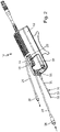
- a catheter pump 10 with a drive unit 12 and with a catheter 18 that can be coupled to the drive unit 12 is shown.
- the catheter 18 has a pump head 15 at its distal end for insertion into the arterial vascular system such as the aorta.
- the catheter 18 is intended to be introduced into the body of a mammal, such as a human, via the femoral artery and to be positioned, for example, in the aorta for cardiac circulatory assistance.
- the catheter 18 is relatively long so that it can extend from the percutaneous insertion site in, for example, the femoral artery into the groin and up the aortic arch.
- a rotor shaft 32 is provided in the catheter 18, by means of which a conveying element provided in the pump head 15, for example a rotor with fold-out propellers, can be rotated.
- the drive unit 12 has a receptacle 14 .
- the proximal end 16 of the catheter 18 is arranged in the receptacle 14 and is securely held there by means of a holding element 20 .
- the catheter 18 has a coupling section 30 that can be inserted into the drive unit 12, by means of which the rotor shaft 32, and thus the conveying element, can ultimately be rotated.
- hoses 22, 24 are provided at the distal end 16. Flushing fluid can be introduced into the catheter 18 via the hose 22 via an inlet 26 . This flushing fluid is conducted through the catheter 18 to the pump head 15 . In the pump head 15, part of this rinsing fluid is fed back through the catheter 18 and discharged via an outlet 28 and the hose 24. That Returned flushing fluid is returned between the rotor shaft 32 rotating during operation and an inner catheter 33 .
- the inner catheter 33 is surrounded by an outer catheter 35 , flushing fluid being conveyed through the lumen between the inner catheter 33 and the outer catheter 35 to the pump head 15 .
- the hoses 22, 24 each have a connecting piece 36, 38. These connecting pieces 36, 38 can be connected to a flushing system, which is described in more detail below.
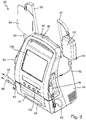
- the flushing system is in the Figures 3 and 4 1 and designated generally by the reference numeral 40.
- FIG. First, the flushing system 40 includes a console 42. This includes two hooks 44, 46 on its rear side, by means of which the console can be fastened to a hospital bed, for example. Furthermore, the console 42 includes a holding portion 48 so that the console 42 can be conveniently carried by an operator.
- the console also includes an in figure 4 recognizable receptacle 50, which can be closed by a pivotable closing element 51.
- the console 42 comprises a pump 52 designed as a linear peristaltic pump.
- This pump 52 is described below with reference to FIG figures 4 and 7 Described in more detail:
- the pump 52 includes a camshaft 56 with a number of cams, not shown.
- the cams are each coupled for movement with a finger 54 .
- These fingers 54 move in the radial direction, ie perpendicular to the axis of rotation of the camshaft 56.
- the fingers 54 move sequentially, that is to say the fingers 54 move together in a wave-like manner. In figure 4 the fingers can be seen protruding into the receptacle 50 and covered by a cover 58 .
- a carrier element 60 with a feed line 62 and a discharge line 64 can be arranged in the receptacle 50 .
- the supply line 62 includes a connector 66 while the discharge line 64 includes a connector 68 .
- the connection piece 66 is here connected to the connection piece 36 of the tube 22 of the catheter pump 10 (cf. figure 2 ) connectable.
- the connectors 66 and 36 can form a luer connector.
- the connection piece 68 of the discharge line 64 can be connected to the connection piece 38 of the tube 24 of the catheter pump 10 .
- the connectors 38 and 68 can also form a luer connector.
- the carrier element 60 extends in a main extension plane and is constructed in the manner of a cassette.
- the carrier element 60 consists of PET and is produced by plastic deep-drawing or injection molding.
- the supply line 62 and the discharge line 64 are fastened to the carrier element 60 or run through the carrier element 60 .
- the carrier element 60 has channels in which the lines 62, 64 are guided.
- the carrier element 60 has a rectangular opening 70 in the middle region. The lines 62, 64 extend along this opening 70 and bridge it.
- the supply line 62 includes a pump section 72.
- the discharge line 64 includes a pump section 74.
- the pump section 72 has a diameter d1
- the pump section 74 has a diameter d2.
- the diameter d1 is larger than the diameter d2. The function of this diameter difference will be described in more detail below.
- the carrier element 60 has two membranes 76, 78, which can consist in particular of silicone. A pressure measurement in the supply line 62 or the discharge line 64 can be carried out by means of these membranes 76, 78, as will be described in more detail below.
- the carrier element 60 has a further opening 80 . This opening 80 is bridged only by the supply line 62.
- the feed line 62 has a further connection piece 82 .
- the feed tube 62 can be connected to a bag 84 by means of this connecting piece 82 .
- Bag 84 contains flushing fluid.
- the bag 84 is attached to a mounting hook 85 of the console 42.
- the supply line 62 includes a container 86 with an enlarged diameter.
- This container 86 lies between the connecting piece 82 and the support element 60.
- the container 86 can be fastened to a receptacle 88 on the console and rests against a window 90 on the console.
- a level measurement of the feed line 62 can be provided, for example by means of a capacitive sensor.
- the discharge line 64 also has a connection piece 92 .
- the connecting piece 92 can be connected to a collection bag 94 for used flushing fluid.
- the collection bag 94 is also attached to a fastening hook 95 of the console 42 .
- the fastening hooks 85, 95 together with the bags 84, 94 are provided on opposite narrow sides of the console 42.
- the bracket has a number of fixing bolts 96 for fixing the carrier element 60 in the receptacle 50 .
- the receptacle 50 can be closed, as in FIG figure 3 is shown.
- the closing element 51 has a closing flap 98 for closing it.
- the closing flap 98 is in figure 8 particularly clearly visible. This is pivotable. To close the closing element 51, the closing flap 98 is pivoted so that Teeth 100 of the closing flap 98 engage behind a console-side fastening web 102, so that the closing element 51 is securely closed in the closed position.
- the supply line 62 is fed into the console 42 on one side of the latter and fed out on an opposite side.
- the discharge line 64 is led into and out of the console 42 on the same side thereof, namely on the side where the discharge line 64 is led out of the console 42 in the direction of the catheter pump 10 .
- the drain line 64 is in an arc (in 6 recognizable) passed through the carrier element 60, so that the discharge line 64 has an arcuate section 69.
- the closing element 51 In order to pressurize the supply line 62 and the discharge line 64 against the fingers 54 of the pump 52 in the closed position of the closing element 51, the closing element 51 has a pressing element 104, 106 for the supply line 62 and the discharge line 64, respectively. These pressing elements 104, 106 are in figure 7 clearly visible. These each extend along the pump sections 72, 74 and are acted upon at the lateral ends by at least one spring element 108, 110 against the fingers 54. As in figure 4 As can be seen, a cover 112 is positioned over the push members 104,106.
- the closing element 51 also has a figure 7 to be recognized urging element 114, 116, a compression spring 118, 120 being provided here as well.
- the application elements 114, 116 act here with the membranes 66, 68 and the sensor elements 122, 124 provided on the console side (cf. figure 4 ) together, so that a pressure measurement in the supply line 62 and in the discharge line 64 is possible.
- carrier element 60 engages a sensor element 126 on the console and a web 128 on the closing element side, which act on the supply line 62 in such a way that air bubble detection can be carried out. This is because, if possible, no air bubbles or other gas bubbles should be allowed to pass through the supply line 62 . In this case, air bubble detection can be carried out, for example, by means of optical methods or by means of capacitive measurement.
- the flushing system 40 then functions as follows: First, the flushing system 40 is connected to the catheter pump 10 in order to form a catheter pump system. The connection 66 of the feed line 62 is thereby connected to the connection 36 of the catheter pump. Likewise, the connection 68 of the discharge line 64 is connected to the connection 38 of the catheter pump 10 . Then the pump 52 can be started. Rinsing fluid is then fed from the bag 84 via the feed line 62 to the tube 22 and the catheter 18 of the catheter pump 10 . The rinsing fluid can consist of a 20% sterile glucose solution. Heparin can be added to the flushing fluid. The amount of rinsing fluid can be set to 600-2500ml/24h during operation, and when filling with a significantly higher flow, approx. 12000ml/24h.
- the flushing fluid then flows through the catheter 10 in the distal direction. A portion of the flushing fluid is then returned through the catheter 18 in the proximal direction and acts as a lubricant for the rotor shaft 32 of the catheter 18. The flushing fluid also effectively prevents blood from entering the catheter 18.
- the used flushing fluid is then fed to the collection bag 94 via the hose 24 and the return line 64 . Due to the fact that the diameter d2 of the pump section 74 of the return line 64 is smaller than the diameter d1 of the pump section 72 of the supply line 62, the pump section 64 cooperates the pump 52 together as a throttle point.
- the cross-sectional area of the diameter d2 of the pump section 74 of the return line 64 is also approximately only one third of the cross-sectional area with the diameter d1 of the pump section 72 of the supply line 62.
- the linear peristaltic pump 52 is a positive displacement pump in which the flushing fluid to be delivered is pushed through by external mechanical deformation of the lines 62, 64 or their pump sections 72, 74, with the compressed section of the pump sections 72, 74 "wandering" due to the sequential axial Movement of fingers 54.
- Sensor elements 122, 124 can be used to measure the pressure in lines 62, 64, while sensor element 126 can be used to detect air bubbles in supply line 62.
- the main functions of the console 42 are to monitor and control the speed of the catheter pump 10 and the flow rate of the irrigation fluid.
- the console 42 has two monitors on one broad side.
- the first monitor 130 serves as the main monitor and is designed as a touch screen. All control and monitoring parameters for the system are displayed on monitor 130.
- An operating system such as Windows, is used here as an input system on the screen.
- a separate operating system which is specially designed for the medical electronics, is used to control the catheter pump 10 and/or the rinsing system 40.
- the control for the medical electronics is used here in particular to control the speed of the catheter pump 10 or the pump 52 of the flushing system 40.
- the console 42 has a second emergency monitor 132 on it. This has only a few functions, such as displaying the speed of the catheter pump 10. This so-called SUI (safety user interface) can only be used to end the operation of the catheter pump 10 and/or the flushing system 40, but not to start it.
- SUI safety user interface
Applications Claiming Priority (2)
| Application Number | Priority Date | Filing Date | Title |
|---|---|---|---|
| DE102017102829.3A DE102017102829A1 (de) | 2017-02-13 | 2017-02-13 | Spülsystem |
| PCT/EP2018/051053 WO2018145865A1 (de) | 2017-02-13 | 2018-01-17 | Spülsystem |
Publications (2)
| Publication Number | Publication Date |
|---|---|
| EP3579903A1 EP3579903A1 (de) | 2019-12-18 |
| EP3579903B1 true EP3579903B1 (de) | 2022-12-21 |
Family
ID=61017922
Family Applications (1)
| Application Number | Title | Priority Date | Filing Date |
|---|---|---|---|
| EP18701009.5A Active EP3579903B1 (de) | 2017-02-13 | 2018-01-17 | Spülsystem |
Country Status (9)
| Country | Link |
|---|---|
| US (1) | US11679232B2 (zh) |
| EP (1) | EP3579903B1 (zh) |
| JP (1) | JP6882495B2 (zh) |
| CN (1) | CN110290826B (zh) |
| BR (1) | BR112019016609A2 (zh) |
| DE (1) | DE102017102829A1 (zh) |
| ES (1) | ES2940085T3 (zh) |
| RU (1) | RU2721583C1 (zh) |
| WO (1) | WO2018145865A1 (zh) |
Families Citing this family (3)
| Publication number | Priority date | Publication date | Assignee | Title |
|---|---|---|---|---|
| JP2021518249A (ja) | 2018-03-20 | 2021-08-02 | セカンド・ハート・アシスト・インコーポレイテッド | 循環補助ポンプ |
| US11690997B2 (en) | 2018-04-06 | 2023-07-04 | Puzzle Medical Devices Inc. | Mammalian body conduit intralumenal device and lumen wall anchor assembly, components thereof and methods of implantation and explanation thereof |
| CN115055455B (zh) * | 2022-06-09 | 2023-05-16 | 江阴市人民医院 | 一种外科护理用的辅助清洗设备 |
Family Cites Families (39)
| Publication number | Priority date | Publication date | Assignee | Title |
|---|---|---|---|---|
| US3306228A (en) * | 1965-08-20 | 1967-02-28 | Trw Inc | Combination gear and vane pump |
| IL44372A (en) * | 1974-03-08 | 1976-10-31 | Drori Mordeki | Fluid-driven feeding device for liquid materials |
| DE3132790A1 (de) | 1981-08-19 | 1983-03-17 | Dr. Eduard Fresenius, Chemisch-pharmazeutische Industrie KG, 6380 Bad Homburg | Kuenstliche niere |
| DE8418491U1 (de) * | 1984-06-19 | 1984-09-20 | Richard Wolf Gmbh, 7134 Knittlingen | Schlauchpumpe fuer spuelfluessigkeiten |
| EP0172336A1 (de) * | 1984-08-24 | 1986-02-26 | GebràDer Sulzer Aktiengesellschaft | Vorrichtung zum gleichmässigen Verteilen eines Zwei-Phasengemisches |
| US4976590A (en) * | 1988-06-08 | 1990-12-11 | Baldwin Brian E | Fluid conduit-responsively adjustable pump arrangement and pump/conduit arrangement and method, and fluid conduits therefor |
| US5098261A (en) * | 1990-05-04 | 1992-03-24 | Brandel Corporation | Peristaltic pump and method for adjustable flow regulation |
| US5340290A (en) * | 1992-12-21 | 1994-08-23 | Scilog, Inc. | Double feed peristaltic pump |
| US5403277A (en) * | 1993-01-12 | 1995-04-04 | Minnesota Mining And Manufacturing Company | Irrigation system with tubing cassette |
| US5460490A (en) * | 1994-05-19 | 1995-10-24 | Linvatec Corporation | Multi-purpose irrigation/aspiration pump system |
| EP0711570A1 (en) * | 1994-11-14 | 1996-05-15 | Siemens-Elema AB | Method and device for internal cleaning of an implanted infusion system |
| JP2891669B2 (ja) | 1996-05-21 | 1999-05-17 | メディス有限会社 | 溶液混合移送装置及び灌流装置 |
| IL120654A (en) * | 1997-04-11 | 2001-08-08 | Nestle Sa | Administration of two liquids to a patient |
| JP4225611B2 (ja) * | 1998-08-27 | 2009-02-18 | オリンパス株式会社 | 内視鏡用管路洗滌装置 |
| JP2000229063A (ja) * | 1999-02-10 | 2000-08-22 | Fuji Photo Optical Co Ltd | 内視鏡管路の洗浄装置 |
| US6585692B1 (en) * | 1999-02-19 | 2003-07-01 | Alsius Corporation | Method and system for patient temperature management and central venous access |
| JP2001218841A (ja) * | 2000-02-08 | 2001-08-14 | Terumo Corp | 輸液ポンプ用カセットおよびそれを用いた輸液ポンプ |
| US6659976B2 (en) * | 2001-04-16 | 2003-12-09 | Zevek, Inc. | Feeding set adaptor |
| DE20209663U1 (de) | 2002-06-21 | 2003-10-23 | Braun Melsungen Ag | Infusionspumpe |
| US7238010B2 (en) * | 2003-04-14 | 2007-07-03 | Stryker Corporation | Surgical irrigation pump and tool system |
| US7591639B2 (en) * | 2004-04-27 | 2009-09-22 | Hewlett-Packard Development Company, L.P. | Peristaltic pump |
| DE102006022122A1 (de) * | 2006-05-11 | 2007-11-15 | Fresenius Medical Care Deutschland Gmbh | Verfahren zur Füllung und Spülung eines Blutschlauchsatzes |
| US20090053085A1 (en) * | 2007-08-24 | 2009-02-26 | Thompson Loren M | Peristalitic pump assembly and method for attaching a cassette thereto |
| CA2971041C (en) * | 2007-10-12 | 2019-11-19 | Deka Products Limited Partnership | Apparatus and methods for hemodialysis |
| US8114276B2 (en) * | 2007-10-24 | 2012-02-14 | Baxter International Inc. | Personal hemodialysis system |
| JP5058759B2 (ja) * | 2007-11-28 | 2012-10-24 | 富士フイルム株式会社 | 内視鏡搬送ケース |
| US9827367B2 (en) * | 2008-04-29 | 2017-11-28 | Medtronic Xomed, Inc. | Surgical instrument, system, and method for frontal sinus irrigation |
| BRPI0911493B8 (pt) | 2008-06-23 | 2021-06-22 | Cardiobridge Gmbh | bomba de cateter para suporte circulatório |
| US8388582B2 (en) * | 2009-08-12 | 2013-03-05 | Medrad, Inc. | Systems and methods for operating interventional catheters using a common operating console and adaptive interface components |
| JP2011206211A (ja) * | 2010-03-29 | 2011-10-20 | Terumo Corp | 輸液ポンプ |
| DE102010031793B4 (de) | 2010-07-30 | 2012-12-06 | Günter Heeke | Bilanzierungspumpenanordnung und Leitungsanordnung dafür |
| US8377001B2 (en) * | 2010-10-01 | 2013-02-19 | Abbott Laboratories | Feeding set for a peristaltic pump system |
| KR102049709B1 (ko) * | 2012-11-14 | 2020-01-08 | 코비디엔 엘피 | 연동 펌프 카세트 |
| CA2882220A1 (en) * | 2012-12-11 | 2014-06-19 | Alcon Research Ltd. | Phacoemulsification hand piece with integrated aspiration and irrigation pump |
| CN103961757B (zh) * | 2013-01-29 | 2016-08-03 | 中国人民解放军总医院 | 智能膀胱冲洗控制系统 |
| EP3834876B1 (en) * | 2013-03-13 | 2022-09-14 | Tc1 Llc | Fluid handling system |
| CN105979982B (zh) * | 2014-12-12 | 2017-11-14 | 泽维克斯公司 | 输液泵盒以及被构造成有助于盒移除的盒接口 |
| WO2016161060A1 (en) * | 2015-04-03 | 2016-10-06 | Orczy-Timko Benedek | Surgical fluid management system |
| CN105840471A (zh) * | 2016-05-04 | 2016-08-10 | 嘉兴栋马童车有限公司 | 蠕动泵 |
-
2017
- 2017-02-13 DE DE102017102829.3A patent/DE102017102829A1/de active Pending
-
2018
- 2018-01-17 CN CN201880011636.2A patent/CN110290826B/zh active Active
- 2018-01-17 ES ES18701009T patent/ES2940085T3/es active Active
- 2018-01-17 RU RU2019128571A patent/RU2721583C1/ru active
- 2018-01-17 US US16/484,814 patent/US11679232B2/en active Active
- 2018-01-17 JP JP2019541787A patent/JP6882495B2/ja active Active
- 2018-01-17 EP EP18701009.5A patent/EP3579903B1/de active Active
- 2018-01-17 WO PCT/EP2018/051053 patent/WO2018145865A1/de active Application Filing
- 2018-01-17 BR BR112019016609-2A patent/BR112019016609A2/pt active Search and Examination
Also Published As
| Publication number | Publication date |
|---|---|
| JP2020507384A (ja) | 2020-03-12 |
| CN110290826B (zh) | 2021-09-10 |
| DE102017102829A1 (de) | 2018-08-16 |
| JP6882495B2 (ja) | 2021-06-02 |
| EP3579903A1 (de) | 2019-12-18 |
| US11679232B2 (en) | 2023-06-20 |
| ES2940085T3 (es) | 2023-05-03 |
| US20200023158A1 (en) | 2020-01-23 |
| CN110290826A (zh) | 2019-09-27 |
| RU2721583C1 (ru) | 2020-05-20 |
| BR112019016609A2 (pt) | 2020-03-31 |
| WO2018145865A1 (de) | 2018-08-16 |
Similar Documents
| Publication | Publication Date | Title |
|---|---|---|
| EP0826383B1 (de) | Anordnung zum On-Line Spülen und Befüllen eines extrakorporalen Blutkreislaufes von Dialysiermaschinen | |
| EP3579903B1 (de) | Spülsystem | |
| EP1539271B1 (de) | Blutbehandlungsvorrichtung mit blutrückgabe | |
| DE102005001779B4 (de) | Disposable zum Betreiben einer Blutbehandlungsvorrichtung im Einnadel- oder Zweinadel-Betrieb | |
| DE102006012087B4 (de) | Verfahren zum zumindest teilweise Entleeren eines extrakorporalen Blutkreislaufs und Hämodialysegerät zur Anwendung des Verfahrens | |
| EP2303355B1 (de) | Vorrichtung zur peritonealdialyse | |
| EP2819631B1 (de) | Spike mit rückschlagventilfunktion sowie befüllvorrichtung eines flüssigkeitssystems mit spike | |
| DE10040403A1 (de) | Intrakardiale Blutpumpe | |
| DE102006022122A1 (de) | Verfahren zur Füllung und Spülung eines Blutschlauchsatzes | |
| DE102014004476A1 (de) | Peristaltische Pumpe, Pumpvorrichtung und tragbare Blutbehandlungsvorrichtung | |
| DE4208054C2 (de) | Leitungs-System zum Spülen eines extrakorporalen Kreislaufs bei der Hämodialyse, Hämofiltration und Hämodiafiltration | |
| DE102011108777A1 (de) | Verfahren zum Entfernen von Blut aus einem extrakorporalen Blutkreislauf sowie Vorrichtungen | |
| EP1727574B1 (de) | Vorrichtung zum wechseln und/oder andocken von funktionsmodulen | |
| DE102011015075B4 (de) | Blutschlauchabschnitt zum extrakorporalen Führen von Blut, extrakorporaler Blutkreislauf, Behandlungsvorrichtung sowie Verfahren | |
| DE60106231T2 (de) | Entnahmevorrichtung mit röhrchen unterschiedlichen querschnitts | |
| EP2988661B1 (de) | Steuereinheit und verfahren zur bestimmung eines drucks in einem blutgefäss, insbesondere in einer arteriovenösen fistel | |
| WO2021245110A1 (de) | Verfahren zur diskonnektion | |
| EP3620190A1 (de) | Hämodialyse-geräteanordnung | |
| DE19729022C2 (de) | Doppellumenkanüle | |
| DE102019109811A1 (de) | Rollenpumpe mit Halteabschnitten zum Festlegen eines Pumpenschlauchsegments | |
| EP4108268A1 (de) | Bidirektionale kanüle | |
| WO2020178301A1 (de) | Extrakorporales blutleitungsset und blutbehandlungsmaschine | |
| EP4136353A1 (de) | Peristaltikpumpe für eine vorrichtung zur extrakorporalen blutbehandlung | |
| EP1214954A1 (de) | Pumpeneinrichtung für eine medizinische Flüssigkeit sowie medizinische Behandlungseinrichtung zum Zuführen einer Flüssigkeit zum menschlichen oder tierischen Körper | |
| DE8517332U1 (de) | Vorrichtung zur Katheterisierung, insbesondere von Nieren bzw. des Nierenbeckens |
Legal Events
| Date | Code | Title | Description |
|---|---|---|---|
| STAA | Information on the status of an ep patent application or granted ep patent |
Free format text: STATUS: UNKNOWN |
|
| STAA | Information on the status of an ep patent application or granted ep patent |
Free format text: STATUS: THE INTERNATIONAL PUBLICATION HAS BEEN MADE |
|
| PUAI | Public reference made under article 153(3) epc to a published international application that has entered the european phase |
Free format text: ORIGINAL CODE: 0009012 |
|
| STAA | Information on the status of an ep patent application or granted ep patent |
Free format text: STATUS: REQUEST FOR EXAMINATION WAS MADE |
|
| 17P | Request for examination filed |
Effective date: 20190829 |
|
| AK | Designated contracting states |
Kind code of ref document: A1 Designated state(s): AL AT BE BG CH CY CZ DE DK EE ES FI FR GB GR HR HU IE IS IT LI LT LU LV MC MK MT NL NO PL PT RO RS SE SI SK SM TR |
|
| AX | Request for extension of the european patent |
Extension state: BA ME |
|
| DAV | Request for validation of the european patent (deleted) | ||
| DAX | Request for extension of the european patent (deleted) | ||
| GRAP | Despatch of communication of intention to grant a patent |
Free format text: ORIGINAL CODE: EPIDOSNIGR1 |
|
| STAA | Information on the status of an ep patent application or granted ep patent |
Free format text: STATUS: GRANT OF PATENT IS INTENDED |
|
| RIC1 | Information provided on ipc code assigned before grant |
Ipc: A61M 60/226 20210101ALI20220622BHEP Ipc: A61M 60/808 20210101ALI20220622BHEP Ipc: A61M 60/554 20210101ALI20220622BHEP Ipc: A61M 60/408 20210101ALI20220622BHEP Ipc: A61M 60/13 20210101ALI20220622BHEP Ipc: F04B 43/12 20060101ALI20220622BHEP Ipc: A61M 5/142 20060101ALI20220622BHEP Ipc: A61M 25/00 20060101AFI20220622BHEP |
|
| INTG | Intention to grant announced |
Effective date: 20220707 |
|
| GRAS | Grant fee paid |
Free format text: ORIGINAL CODE: EPIDOSNIGR3 |
|
| GRAA | (expected) grant |
Free format text: ORIGINAL CODE: 0009210 |
|
| STAA | Information on the status of an ep patent application or granted ep patent |
Free format text: STATUS: THE PATENT HAS BEEN GRANTED |
|
| AK | Designated contracting states |
Kind code of ref document: B1 Designated state(s): AL AT BE BG CH CY CZ DE DK EE ES FI FR GB GR HR HU IE IS IT LI LT LU LV MC MK MT NL NO PL PT RO RS SE SI SK SM TR |
|
| REG | Reference to a national code |
Ref country code: GB Ref legal event code: FG4D Free format text: NOT ENGLISH |
|
| REG | Reference to a national code |
Ref country code: DE Ref legal event code: R096 Ref document number: 502018011263 Country of ref document: DE |
|
| REG | Reference to a national code |
Ref country code: CH Ref legal event code: EP |
|
| REG | Reference to a national code |
Ref country code: AT Ref legal event code: REF Ref document number: 1538682 Country of ref document: AT Kind code of ref document: T Effective date: 20230115 |
|
| REG | Reference to a national code |
Ref country code: IE Ref legal event code: FG4D Free format text: LANGUAGE OF EP DOCUMENT: GERMAN |
|
| REG | Reference to a national code |
Ref country code: LT Ref legal event code: MG9D |
|
| REG | Reference to a national code |
Ref country code: NL Ref legal event code: MP Effective date: 20221221 |
|
| PG25 | Lapsed in a contracting state [announced via postgrant information from national office to epo] |
Ref country code: SE Free format text: LAPSE BECAUSE OF FAILURE TO SUBMIT A TRANSLATION OF THE DESCRIPTION OR TO PAY THE FEE WITHIN THE PRESCRIBED TIME-LIMIT Effective date: 20221221 Ref country code: NO Free format text: LAPSE BECAUSE OF FAILURE TO SUBMIT A TRANSLATION OF THE DESCRIPTION OR TO PAY THE FEE WITHIN THE PRESCRIBED TIME-LIMIT Effective date: 20230321 Ref country code: LT Free format text: LAPSE BECAUSE OF FAILURE TO SUBMIT A TRANSLATION OF THE DESCRIPTION OR TO PAY THE FEE WITHIN THE PRESCRIBED TIME-LIMIT Effective date: 20221221 Ref country code: FI Free format text: LAPSE BECAUSE OF FAILURE TO SUBMIT A TRANSLATION OF THE DESCRIPTION OR TO PAY THE FEE WITHIN THE PRESCRIBED TIME-LIMIT Effective date: 20221221 |
|
| PGFP | Annual fee paid to national office [announced via postgrant information from national office to epo] |
Ref country code: FR Payment date: 20230124 Year of fee payment: 6 Ref country code: ES Payment date: 20230216 Year of fee payment: 6 Ref country code: CH Payment date: 20230131 Year of fee payment: 6 |
|
| REG | Reference to a national code |
Ref country code: ES Ref legal event code: FG2A Ref document number: 2940085 Country of ref document: ES Kind code of ref document: T3 Effective date: 20230503 |
|
| PG25 | Lapsed in a contracting state [announced via postgrant information from national office to epo] |
Ref country code: RS Free format text: LAPSE BECAUSE OF FAILURE TO SUBMIT A TRANSLATION OF THE DESCRIPTION OR TO PAY THE FEE WITHIN THE PRESCRIBED TIME-LIMIT Effective date: 20221221 Ref country code: LV Free format text: LAPSE BECAUSE OF FAILURE TO SUBMIT A TRANSLATION OF THE DESCRIPTION OR TO PAY THE FEE WITHIN THE PRESCRIBED TIME-LIMIT Effective date: 20221221 Ref country code: HR Free format text: LAPSE BECAUSE OF FAILURE TO SUBMIT A TRANSLATION OF THE DESCRIPTION OR TO PAY THE FEE WITHIN THE PRESCRIBED TIME-LIMIT Effective date: 20221221 Ref country code: GR Free format text: LAPSE BECAUSE OF FAILURE TO SUBMIT A TRANSLATION OF THE DESCRIPTION OR TO PAY THE FEE WITHIN THE PRESCRIBED TIME-LIMIT Effective date: 20230322 |
|
| PGFP | Annual fee paid to national office [announced via postgrant information from national office to epo] |
Ref country code: TR Payment date: 20230216 Year of fee payment: 6 Ref country code: IT Payment date: 20230329 Year of fee payment: 6 Ref country code: GB Payment date: 20230117 Year of fee payment: 6 Ref country code: DE Payment date: 20230313 Year of fee payment: 6 |
|
| PG25 | Lapsed in a contracting state [announced via postgrant information from national office to epo] |
Ref country code: NL Free format text: LAPSE BECAUSE OF FAILURE TO SUBMIT A TRANSLATION OF THE DESCRIPTION OR TO PAY THE FEE WITHIN THE PRESCRIBED TIME-LIMIT Effective date: 20221221 |
|
| P01 | Opt-out of the competence of the unified patent court (upc) registered |
Effective date: 20230601 |
|
| PG25 | Lapsed in a contracting state [announced via postgrant information from national office to epo] |
Ref country code: SM Free format text: LAPSE BECAUSE OF FAILURE TO SUBMIT A TRANSLATION OF THE DESCRIPTION OR TO PAY THE FEE WITHIN THE PRESCRIBED TIME-LIMIT Effective date: 20221221 Ref country code: RO Free format text: LAPSE BECAUSE OF FAILURE TO SUBMIT A TRANSLATION OF THE DESCRIPTION OR TO PAY THE FEE WITHIN THE PRESCRIBED TIME-LIMIT Effective date: 20221221 Ref country code: PT Free format text: LAPSE BECAUSE OF FAILURE TO SUBMIT A TRANSLATION OF THE DESCRIPTION OR TO PAY THE FEE WITHIN THE PRESCRIBED TIME-LIMIT Effective date: 20230421 Ref country code: EE Free format text: LAPSE BECAUSE OF FAILURE TO SUBMIT A TRANSLATION OF THE DESCRIPTION OR TO PAY THE FEE WITHIN THE PRESCRIBED TIME-LIMIT Effective date: 20221221 Ref country code: CZ Free format text: LAPSE BECAUSE OF FAILURE TO SUBMIT A TRANSLATION OF THE DESCRIPTION OR TO PAY THE FEE WITHIN THE PRESCRIBED TIME-LIMIT Effective date: 20221221 |
|
| PG25 | Lapsed in a contracting state [announced via postgrant information from national office to epo] |
Ref country code: SK Free format text: LAPSE BECAUSE OF FAILURE TO SUBMIT A TRANSLATION OF THE DESCRIPTION OR TO PAY THE FEE WITHIN THE PRESCRIBED TIME-LIMIT Effective date: 20221221 Ref country code: PL Free format text: LAPSE BECAUSE OF FAILURE TO SUBMIT A TRANSLATION OF THE DESCRIPTION OR TO PAY THE FEE WITHIN THE PRESCRIBED TIME-LIMIT Effective date: 20221221 Ref country code: IS Free format text: LAPSE BECAUSE OF FAILURE TO SUBMIT A TRANSLATION OF THE DESCRIPTION OR TO PAY THE FEE WITHIN THE PRESCRIBED TIME-LIMIT Effective date: 20230421 Ref country code: AL Free format text: LAPSE BECAUSE OF FAILURE TO SUBMIT A TRANSLATION OF THE DESCRIPTION OR TO PAY THE FEE WITHIN THE PRESCRIBED TIME-LIMIT Effective date: 20221221 |
|
| REG | Reference to a national code |
Ref country code: DE Ref legal event code: R097 Ref document number: 502018011263 Country of ref document: DE |
|
| PG25 | Lapsed in a contracting state [announced via postgrant information from national office to epo] |
Ref country code: MC Free format text: LAPSE BECAUSE OF FAILURE TO SUBMIT A TRANSLATION OF THE DESCRIPTION OR TO PAY THE FEE WITHIN THE PRESCRIBED TIME-LIMIT Effective date: 20221221 Ref country code: LU Free format text: LAPSE BECAUSE OF NON-PAYMENT OF DUE FEES Effective date: 20230117 |
|
| REG | Reference to a national code |
Ref country code: BE Ref legal event code: MM Effective date: 20230131 |
|
| PLBE | No opposition filed within time limit |
Free format text: ORIGINAL CODE: 0009261 |
|
| STAA | Information on the status of an ep patent application or granted ep patent |
Free format text: STATUS: NO OPPOSITION FILED WITHIN TIME LIMIT |
|
| PG25 | Lapsed in a contracting state [announced via postgrant information from national office to epo] |
Ref country code: DK Free format text: LAPSE BECAUSE OF FAILURE TO SUBMIT A TRANSLATION OF THE DESCRIPTION OR TO PAY THE FEE WITHIN THE PRESCRIBED TIME-LIMIT Effective date: 20221221 |
|
| 26N | No opposition filed |
Effective date: 20230922 |
|
| PG25 | Lapsed in a contracting state [announced via postgrant information from national office to epo] |
Ref country code: BE Free format text: LAPSE BECAUSE OF NON-PAYMENT OF DUE FEES Effective date: 20230131 |
|
| PG25 | Lapsed in a contracting state [announced via postgrant information from national office to epo] |
Ref country code: SI Free format text: LAPSE BECAUSE OF FAILURE TO SUBMIT A TRANSLATION OF THE DESCRIPTION OR TO PAY THE FEE WITHIN THE PRESCRIBED TIME-LIMIT Effective date: 20221221 Ref country code: IE Free format text: LAPSE BECAUSE OF NON-PAYMENT OF DUE FEES Effective date: 20230117 |
|
| REG | Reference to a national code |
Ref country code: AT Ref legal event code: MM01 Ref document number: 1538682 Country of ref document: AT Kind code of ref document: T Effective date: 20230117 |
|
| PGFP | Annual fee paid to national office [announced via postgrant information from national office to epo] |
Ref country code: ES Payment date: 20240216 Year of fee payment: 7 |