EP3834876B1 - Fluid handling system - Google Patents
Fluid handling system Download PDFInfo
- Publication number
- EP3834876B1 EP3834876B1 EP21150599.5A EP21150599A EP3834876B1 EP 3834876 B1 EP3834876 B1 EP 3834876B1 EP 21150599 A EP21150599 A EP 21150599A EP 3834876 B1 EP3834876 B1 EP 3834876B1
- Authority
- EP
- European Patent Office
- Prior art keywords
- interface member
- console
- pump
- catheter
- assembly
- Prior art date
- Legal status (The legal status is an assumption and is not a legal conclusion. Google has not performed a legal analysis and makes no representation as to the accuracy of the status listed.)
- Active
Links
- 239000012530 fluid Substances 0.000 title claims description 107
- 238000001802 infusion Methods 0.000 claims description 22
- 239000002699 waste material Substances 0.000 claims description 18
- 238000004891 communication Methods 0.000 claims description 14
- 230000037452 priming Effects 0.000 description 45
- 238000000034 method Methods 0.000 description 40
- 238000011282 treatment Methods 0.000 description 20
- 230000007246 mechanism Effects 0.000 description 18
- 239000008280 blood Substances 0.000 description 11
- 210000004369 blood Anatomy 0.000 description 11
- 239000007788 liquid Substances 0.000 description 9
- FAPWRFPIFSIZLT-UHFFFAOYSA-M Sodium chloride Chemical compound [Na+].[Cl-] FAPWRFPIFSIZLT-UHFFFAOYSA-M 0.000 description 8
- 238000003780 insertion Methods 0.000 description 8
- 230000037431 insertion Effects 0.000 description 8
- 238000007789 sealing Methods 0.000 description 8
- 239000011780 sodium chloride Substances 0.000 description 8
- 210000005240 left ventricle Anatomy 0.000 description 7
- 238000005086 pumping Methods 0.000 description 7
- 206010007556 Cardiac failure acute Diseases 0.000 description 5
- 239000008155 medical solution Substances 0.000 description 5
- 230000002572 peristaltic effect Effects 0.000 description 5
- 230000008901 benefit Effects 0.000 description 4
- 210000005166 vasculature Anatomy 0.000 description 4
- 206010019280 Heart failures Diseases 0.000 description 3
- 210000000709 aorta Anatomy 0.000 description 3
- 238000013459 approach Methods 0.000 description 3
- 230000000747 cardiac effect Effects 0.000 description 3
- 206010007625 cardiogenic shock Diseases 0.000 description 3
- 230000001050 lubricating effect Effects 0.000 description 3
- 238000012986 modification Methods 0.000 description 3
- 230000004048 modification Effects 0.000 description 3
- 208000010125 myocardial infarction Diseases 0.000 description 3
- 230000037361 pathway Effects 0.000 description 3
- 238000013146 percutaneous coronary intervention Methods 0.000 description 3
- 230000008569 process Effects 0.000 description 3
- 230000002792 vascular Effects 0.000 description 3
- 206010018910 Haemolysis Diseases 0.000 description 2
- 230000002411 adverse Effects 0.000 description 2
- 230000008878 coupling Effects 0.000 description 2
- 238000010168 coupling process Methods 0.000 description 2
- 238000005859 coupling reaction Methods 0.000 description 2
- 210000001105 femoral artery Anatomy 0.000 description 2
- 230000006870 function Effects 0.000 description 2
- 230000008588 hemolysis Effects 0.000 description 2
- 238000004519 manufacturing process Methods 0.000 description 2
- 239000012528 membrane Substances 0.000 description 2
- 230000003287 optical effect Effects 0.000 description 2
- 239000002245 particle Substances 0.000 description 2
- 238000003825 pressing Methods 0.000 description 2
- 238000002560 therapeutic procedure Methods 0.000 description 2
- 230000002861 ventricular Effects 0.000 description 2
- 208000005189 Embolism Diseases 0.000 description 1
- 208000007536 Thrombosis Diseases 0.000 description 1
- 230000001154 acute effect Effects 0.000 description 1
- 206010000891 acute myocardial infarction Diseases 0.000 description 1
- 238000011360 adjunctive therapy Methods 0.000 description 1
- 210000003484 anatomy Anatomy 0.000 description 1
- 210000002376 aorta thoracic Anatomy 0.000 description 1
- 210000001765 aortic valve Anatomy 0.000 description 1
- 230000000712 assembly Effects 0.000 description 1
- 238000000429 assembly Methods 0.000 description 1
- 230000006931 brain damage Effects 0.000 description 1
- 231100000874 brain damage Toxicity 0.000 description 1
- 208000029028 brain injury Diseases 0.000 description 1
- 210000000748 cardiovascular system Anatomy 0.000 description 1
- 230000008859 change Effects 0.000 description 1
- 238000001816 cooling Methods 0.000 description 1
- 230000007423 decrease Effects 0.000 description 1
- 230000001934 delay Effects 0.000 description 1
- 238000010586 diagram Methods 0.000 description 1
- 239000003814 drug Substances 0.000 description 1
- 230000002526 effect on cardiovascular system Effects 0.000 description 1
- 229940124645 emergency medicine Drugs 0.000 description 1
- 238000000605 extraction Methods 0.000 description 1
- 230000005484 gravity Effects 0.000 description 1
- 230000005802 health problem Effects 0.000 description 1
- 208000019622 heart disease Diseases 0.000 description 1
- 210000003709 heart valve Anatomy 0.000 description 1
- 238000002513 implantation Methods 0.000 description 1
- 230000001939 inductive effect Effects 0.000 description 1
- 238000005461 lubrication Methods 0.000 description 1
- 238000012544 monitoring process Methods 0.000 description 1
- 238000000465 moulding Methods 0.000 description 1
- 210000004165 myocardium Anatomy 0.000 description 1
- 238000011458 pharmacological treatment Methods 0.000 description 1
- 210000001147 pulmonary artery Anatomy 0.000 description 1
- 238000011084 recovery Methods 0.000 description 1
- 230000008439 repair process Effects 0.000 description 1
- 210000005241 right ventricle Anatomy 0.000 description 1
- 238000005096 rolling process Methods 0.000 description 1
- 238000007493 shaping process Methods 0.000 description 1
- 239000000243 solution Substances 0.000 description 1
- 230000004083 survival effect Effects 0.000 description 1
- 230000007704 transition Effects 0.000 description 1
- 238000013519 translation Methods 0.000 description 1
Images


Classifications
-
- A—HUMAN NECESSITIES
- A61—MEDICAL OR VETERINARY SCIENCE; HYGIENE
- A61M—DEVICES FOR INTRODUCING MEDIA INTO, OR ONTO, THE BODY; DEVICES FOR TRANSDUCING BODY MEDIA OR FOR TAKING MEDIA FROM THE BODY; DEVICES FOR PRODUCING OR ENDING SLEEP OR STUPOR
- A61M1/00—Suction or pumping devices for medical purposes; Devices for carrying-off, for treatment of, or for carrying-over, body-liquids; Drainage systems
- A61M1/36—Other treatment of blood in a by-pass of the natural circulatory system, e.g. temperature adaptation, irradiation ; Extra-corporeal blood circuits
- A61M1/3621—Extra-corporeal blood circuits
- A61M1/3653—Interfaces between patient blood circulation and extra-corporal blood circuit
- A61M1/3659—Cannulae pertaining to extracorporeal circulation
-
- A—HUMAN NECESSITIES
- A61—MEDICAL OR VETERINARY SCIENCE; HYGIENE
- A61M—DEVICES FOR INTRODUCING MEDIA INTO, OR ONTO, THE BODY; DEVICES FOR TRANSDUCING BODY MEDIA OR FOR TAKING MEDIA FROM THE BODY; DEVICES FOR PRODUCING OR ENDING SLEEP OR STUPOR
- A61M60/00—Blood pumps; Devices for mechanical circulatory actuation; Balloon pumps for circulatory assistance
- A61M60/10—Location thereof with respect to the patient's body
- A61M60/122—Implantable pumps or pumping devices, i.e. the blood being pumped inside the patient's body
- A61M60/126—Implantable pumps or pumping devices, i.e. the blood being pumped inside the patient's body implantable via, into, inside, in line, branching on, or around a blood vessel
- A61M60/148—Implantable pumps or pumping devices, i.e. the blood being pumped inside the patient's body implantable via, into, inside, in line, branching on, or around a blood vessel in line with a blood vessel using resection or like techniques, e.g. permanent endovascular heart assist devices
-
- A—HUMAN NECESSITIES
- A61—MEDICAL OR VETERINARY SCIENCE; HYGIENE
- A61M—DEVICES FOR INTRODUCING MEDIA INTO, OR ONTO, THE BODY; DEVICES FOR TRANSDUCING BODY MEDIA OR FOR TAKING MEDIA FROM THE BODY; DEVICES FOR PRODUCING OR ENDING SLEEP OR STUPOR
- A61M1/00—Suction or pumping devices for medical purposes; Devices for carrying-off, for treatment of, or for carrying-over, body-liquids; Drainage systems
- A61M1/14—Dialysis systems; Artificial kidneys; Blood oxygenators ; Reciprocating systems for treatment of body fluids, e.g. single needle systems for hemofiltration or pheresis
- A61M1/15—Dialysis systems; Artificial kidneys; Blood oxygenators ; Reciprocating systems for treatment of body fluids, e.g. single needle systems for hemofiltration or pheresis with a cassette forming partially or totally the flow circuit for the treating fluid, e.g. the dialysate fluid circuit or the treating gas circuit
- A61M1/152—Details related to the interface between cassette and machine
- A61M1/1524—Details related to the interface between cassette and machine the interface providing means for actuating on functional elements of the cassette, e.g. plungers
-
- A—HUMAN NECESSITIES
- A61—MEDICAL OR VETERINARY SCIENCE; HYGIENE
- A61M—DEVICES FOR INTRODUCING MEDIA INTO, OR ONTO, THE BODY; DEVICES FOR TRANSDUCING BODY MEDIA OR FOR TAKING MEDIA FROM THE BODY; DEVICES FOR PRODUCING OR ENDING SLEEP OR STUPOR
- A61M5/00—Devices for bringing media into the body in a subcutaneous, intra-vascular or intramuscular way; Accessories therefor, e.g. filling or cleaning devices, arm-rests
- A61M5/14—Infusion devices, e.g. infusing by gravity; Blood infusion; Accessories therefor
- A61M5/142—Pressure infusion, e.g. using pumps
-
- A—HUMAN NECESSITIES
- A61—MEDICAL OR VETERINARY SCIENCE; HYGIENE
- A61M—DEVICES FOR INTRODUCING MEDIA INTO, OR ONTO, THE BODY; DEVICES FOR TRANSDUCING BODY MEDIA OR FOR TAKING MEDIA FROM THE BODY; DEVICES FOR PRODUCING OR ENDING SLEEP OR STUPOR
- A61M5/00—Devices for bringing media into the body in a subcutaneous, intra-vascular or intramuscular way; Accessories therefor, e.g. filling or cleaning devices, arm-rests
- A61M5/14—Infusion devices, e.g. infusing by gravity; Blood infusion; Accessories therefor
- A61M5/168—Means for controlling media flow to the body or for metering media to the body, e.g. drip meters, counters ; Monitoring media flow to the body
- A61M5/172—Means for controlling media flow to the body or for metering media to the body, e.g. drip meters, counters ; Monitoring media flow to the body electrical or electronic
-
- A—HUMAN NECESSITIES
- A61—MEDICAL OR VETERINARY SCIENCE; HYGIENE
- A61M—DEVICES FOR INTRODUCING MEDIA INTO, OR ONTO, THE BODY; DEVICES FOR TRANSDUCING BODY MEDIA OR FOR TAKING MEDIA FROM THE BODY; DEVICES FOR PRODUCING OR ENDING SLEEP OR STUPOR
- A61M60/00—Blood pumps; Devices for mechanical circulatory actuation; Balloon pumps for circulatory assistance
- A61M60/10—Location thereof with respect to the patient's body
- A61M60/122—Implantable pumps or pumping devices, i.e. the blood being pumped inside the patient's body
- A61M60/126—Implantable pumps or pumping devices, i.e. the blood being pumped inside the patient's body implantable via, into, inside, in line, branching on, or around a blood vessel
- A61M60/13—Implantable pumps or pumping devices, i.e. the blood being pumped inside the patient's body implantable via, into, inside, in line, branching on, or around a blood vessel by means of a catheter allowing explantation, e.g. catheter pumps temporarily introduced via the vascular system
-
- A—HUMAN NECESSITIES
- A61—MEDICAL OR VETERINARY SCIENCE; HYGIENE
- A61M—DEVICES FOR INTRODUCING MEDIA INTO, OR ONTO, THE BODY; DEVICES FOR TRANSDUCING BODY MEDIA OR FOR TAKING MEDIA FROM THE BODY; DEVICES FOR PRODUCING OR ENDING SLEEP OR STUPOR
- A61M60/00—Blood pumps; Devices for mechanical circulatory actuation; Balloon pumps for circulatory assistance
- A61M60/20—Type thereof
- A61M60/205—Non-positive displacement blood pumps
- A61M60/216—Non-positive displacement blood pumps including a rotating member acting on the blood, e.g. impeller
-
- A—HUMAN NECESSITIES
- A61—MEDICAL OR VETERINARY SCIENCE; HYGIENE
- A61M—DEVICES FOR INTRODUCING MEDIA INTO, OR ONTO, THE BODY; DEVICES FOR TRANSDUCING BODY MEDIA OR FOR TAKING MEDIA FROM THE BODY; DEVICES FOR PRODUCING OR ENDING SLEEP OR STUPOR
- A61M60/00—Blood pumps; Devices for mechanical circulatory actuation; Balloon pumps for circulatory assistance
- A61M60/50—Details relating to control
- A61M60/508—Electronic control means, e.g. for feedback regulation
- A61M60/515—Regulation using real-time patient data
- A61M60/531—Regulation using real-time patient data using blood pressure data, e.g. from blood pressure sensors
-
- A—HUMAN NECESSITIES
- A61—MEDICAL OR VETERINARY SCIENCE; HYGIENE
- A61M—DEVICES FOR INTRODUCING MEDIA INTO, OR ONTO, THE BODY; DEVICES FOR TRANSDUCING BODY MEDIA OR FOR TAKING MEDIA FROM THE BODY; DEVICES FOR PRODUCING OR ENDING SLEEP OR STUPOR
- A61M1/00—Suction or pumping devices for medical purposes; Devices for carrying-off, for treatment of, or for carrying-over, body-liquids; Drainage systems
- A61M1/14—Dialysis systems; Artificial kidneys; Blood oxygenators ; Reciprocating systems for treatment of body fluids, e.g. single needle systems for hemofiltration or pheresis
- A61M1/15—Dialysis systems; Artificial kidneys; Blood oxygenators ; Reciprocating systems for treatment of body fluids, e.g. single needle systems for hemofiltration or pheresis with a cassette forming partially or totally the flow circuit for the treating fluid, e.g. the dialysate fluid circuit or the treating gas circuit
- A61M1/155—Dialysis systems; Artificial kidneys; Blood oxygenators ; Reciprocating systems for treatment of body fluids, e.g. single needle systems for hemofiltration or pheresis with a cassette forming partially or totally the flow circuit for the treating fluid, e.g. the dialysate fluid circuit or the treating gas circuit with treatment-fluid pumping means or components thereof
-
- A—HUMAN NECESSITIES
- A61—MEDICAL OR VETERINARY SCIENCE; HYGIENE
- A61M—DEVICES FOR INTRODUCING MEDIA INTO, OR ONTO, THE BODY; DEVICES FOR TRANSDUCING BODY MEDIA OR FOR TAKING MEDIA FROM THE BODY; DEVICES FOR PRODUCING OR ENDING SLEEP OR STUPOR
- A61M60/00—Blood pumps; Devices for mechanical circulatory actuation; Balloon pumps for circulatory assistance
- A61M60/20—Type thereof
- A61M60/247—Positive displacement blood pumps
- A61M60/253—Positive displacement blood pumps including a displacement member directly acting on the blood
- A61M60/268—Positive displacement blood pumps including a displacement member directly acting on the blood the displacement member being flexible, e.g. membranes, diaphragms or bladders
- A61M60/279—Peristaltic pumps, e.g. roller pumps
-
- A—HUMAN NECESSITIES
- A61—MEDICAL OR VETERINARY SCIENCE; HYGIENE
- A61M—DEVICES FOR INTRODUCING MEDIA INTO, OR ONTO, THE BODY; DEVICES FOR TRANSDUCING BODY MEDIA OR FOR TAKING MEDIA FROM THE BODY; DEVICES FOR PRODUCING OR ENDING SLEEP OR STUPOR
- A61M60/00—Blood pumps; Devices for mechanical circulatory actuation; Balloon pumps for circulatory assistance
- A61M60/40—Details relating to driving
- A61M60/403—Details relating to driving for non-positive displacement blood pumps
- A61M60/408—Details relating to driving for non-positive displacement blood pumps the force acting on the blood contacting member being mechanical, e.g. transmitted by a shaft or cable
- A61M60/411—Details relating to driving for non-positive displacement blood pumps the force acting on the blood contacting member being mechanical, e.g. transmitted by a shaft or cable generated by an electromotor
- A61M60/414—Details relating to driving for non-positive displacement blood pumps the force acting on the blood contacting member being mechanical, e.g. transmitted by a shaft or cable generated by an electromotor transmitted by a rotating cable, e.g. for blood pumps mounted on a catheter
-
- A—HUMAN NECESSITIES
- A61—MEDICAL OR VETERINARY SCIENCE; HYGIENE
- A61M—DEVICES FOR INTRODUCING MEDIA INTO, OR ONTO, THE BODY; DEVICES FOR TRANSDUCING BODY MEDIA OR FOR TAKING MEDIA FROM THE BODY; DEVICES FOR PRODUCING OR ENDING SLEEP OR STUPOR
- A61M60/00—Blood pumps; Devices for mechanical circulatory actuation; Balloon pumps for circulatory assistance
- A61M60/50—Details relating to control
- A61M60/508—Electronic control means, e.g. for feedback regulation
- A61M60/538—Regulation using real-time blood pump operational parameter data, e.g. motor current
- A61M60/546—Regulation using real-time blood pump operational parameter data, e.g. motor current of blood flow, e.g. by adapting rotor speed
-
- A—HUMAN NECESSITIES
- A61—MEDICAL OR VETERINARY SCIENCE; HYGIENE
- A61M—DEVICES FOR INTRODUCING MEDIA INTO, OR ONTO, THE BODY; DEVICES FOR TRANSDUCING BODY MEDIA OR FOR TAKING MEDIA FROM THE BODY; DEVICES FOR PRODUCING OR ENDING SLEEP OR STUPOR
- A61M60/00—Blood pumps; Devices for mechanical circulatory actuation; Balloon pumps for circulatory assistance
- A61M60/80—Constructional details other than related to driving
- A61M60/855—Constructional details other than related to driving of implantable pumps or pumping devices
- A61M60/871—Energy supply devices; Converters therefor
- A61M60/878—Electrical connections within the patient's body
Definitions
- This application is directed to pumps for mechanical circulatory support of a heart.
- this application is directed to a console and controller for a catheter pump and a fluid handling system configured to convey and remove fluids to and from the catheter pump.
- Heart disease is a major health problem that has a high mortality rate. Physicians increasingly use mechanical circulatory support systems for treating heart failure. The treatment of acute heart failure requires a device that can provide support to the patient quickly. Physicians desire treatment options that can be deployed quickly and minimally-invasively.
- Intra-aortic balloon pumps are currently the most common type of circulatory support devices for treating acute heart failure.
- IABPs are commonly used to treat heart failure, such as to stabilize a patient after cardiogenic shock, during treatment of acute myocardial infarction (MI) or decompensated heart failure, or to support a patient during high risk percutaneous coronary intervention (PCI).
- Circulatory support systems may be used alone or with pharmacological treatment.
- an IABP is positioned in the aorta and actuated in a counterpulsation fashion to provide partial support to the circulatory system.
- minimally-invasive rotary blood pumps have been developed in an attempt to increase the level of potential support (i.e., higher flow).
- a rotary blood pump is typically inserted into the body and connected to the cardiovascular system, for example, to the left ventricle and the ascending aorta to assist the pumping function of the heart.
- Other known applications pumping venous blood from the right ventricle to the pulmonary artery for support of the right side of the heart.
- An aim of acute circulatory support devices is to reduce the load on the heart muscle for a period of time, to stabilize the patient prior to heart transplant or for continuing support.
- a pump with improved performance and clinical outcomes.
- a pump that can provide elevated flow rates with reduced risk of hemolysis and thrombosis.
- a pump that can be inserted minimally-invasively and provide sufficient flow rates for various indications while reducing the risk of major adverse events.
- a heart pump that can be placed minimally-invasively, for example, through a 5.00mm diameter (15FR) or 4.00mm diameter (12FR) incision.
- a heart pump that can provide an average flow rate of 4 Lpm or more during operation, for example, at 8.27kPa (62 mmHg) of head pressure.
- a controller may be provided to control the flow into and out of the catheter assembly. It can be advantageous to provide improved mechanisms for engaging the catheter assembly with the controller, which may be housed in a console.
- WO 02/081919 describes a programmable pump for injecting medicaments, comprising two parts which can be detachably coupled, i.e. a cassette containing a liquid to be injected, and a pump module provided with actuating means so that the liquid can exit from the cassette.
- the cassette comprises an electronic memory wherein data relating to the prescribed injection program has been previously stored.
- the pump is also characterized in that when the two parts are coupled, the actuating means are electrically connected to the memory and react to data contained therein in order to inject the liquid according to the desired program.
- a micropump that includes: a tube unit which includes a tube having elasticity and a circular-arc-shaped part and a tube guide frame for holding the tube; a control unit which has a plurality of fingers extending from the center of the circular-arc shape of the tube in the radial directions, a cam for sequentially pressing the plural fingers from the inlet side to the outlet side of the tube, a drive unit for giving rotation force to the cam, a control circuit unit for controlling operation of the drive unit, a device frame for holding the plural fingers, the cam, the drive unit, and the control circuit unit; a reservoir communicating with an inlet port of the tube; and a power source for supplying power to the control circuit unit, wherein the tube unit is detachably attached to the control unit substantially in the horizontal direction with respect to the rotation surface of the cam and attached to the inside of a space produced by the device frame.
- the fluid handling system includes a console housing.
- the console housing includes one or more pumps, and a controller configured to operate the pump(s).
- the system further includes a catheter assembly.
- the catheter assembly includes a catheter body having a proximal portion and an operative device at a distal portion.
- An infusion system is in fluid communication with the proximal portion of the catheter body.
- the infusion system includes an interface member configured to be separate from the console housing in a first state and to at least partially secure the infusion system to the console housing in a second state. Upon engagement of the interface member with the console housing in the second state, the infusion system is operably engaged with the pump(s).
- First and second occlusion beds are formed in the interface member.
- the first occlusion bed includes a first arcuate recessed region formed in the interface member and the second occlusion bed include a second arcuate recessed region formed in the interface member.
- the interface member further includes first and second pump tube segments positioned along the occlusion beds formed in the interface member. In the second state, upon engagement of the interface member with the console housing, the one or more pumps engage with the interface member and compress the first and second pump tube segments against the first and second occlusion beds, respectively.
- the method comprises positioning an interface member of the infusion system in an interface aperture of the console housing.
- the interface member comprises an occlusion bed, a tube segment mounted on the interface body near the occlusion bed, and an electrical component.
- the method further comprises inserting the interface member through the interface aperture until a pump roller of the console housing compresses the tube segment against the occlusion bed and until an electrical interconnect of the console housing is electrically coupled to the electrical component of the interface body.
- the catheter assembly includes an elongate body and an operative device.
- the method comprises inserting the operative device of the catheter assembly into a priming vessel.
- the method further comprises securing a proximal portion of the priming vessel to a distal portion of the elongate body, such that the elongate body is in fluid communication with the priming vessel. Fluid is delivered through the elongate body and the priming vessel to expel air within the catheter assembly.
- the disclosed percutaneous heart pump systems may include a catheter assembly and a console that includes a controller configured to control the fluid and electrical pathways that pass through the catheter assembly.
- the console may be configured to control the flow rate of the pump and to monitor various physiological parameters and pump performance through the various electrical and fluid pathways of the catheter assembly.
- the catheter assembly may be disposable, such that the catheter assembly can be discarded after use, while the console and controller are reusable.
- an interface member at a proximal portion of the catheter assembly that is removably engageable with the console.
- it can be important to make the interface easy to use so that users can easily connect the catheter assembly to the console before use and easily remove the catheter assembly from the console after use.
- the interface provides a secure connection between the interface member of the catheter assembly and an interface region of the console to ensure that the catheter assembly remains connected to the console uninterrupted during treatment.
- a catheter assembly is used in a percutaneous heart pump system having an operative device (e.g., an impeller assembly) that is configured to assist the patient's heart in pumping blood.
- the heart pump system may be configured to at least temporarily support the workload of the left ventricle in some applications.
- the exemplary heart pump can be designed for percutaneous entry through the femoral artery to a patient's heart.
- the exemplary impeller assembly can include a collapsible impeller and cannula, which can be inserted into the patient's vasculature at a catheter size of less than 4.33mm in diameter (13 FR), for example, about 4.17mm in diameter (12.5 FR) in some arrangements.
- a sheath may maintain the impeller and cannula assembly in a stored configuration.
- the impeller and cannula can expand to a larger diameter, for example to a catheter size of about 8.00mm in diameter (24 FR) when the sheath is removed from the impeller assembly.
- the expanded diameter of the impeller and cannula may allow for the generation of higher flow rates.
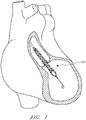
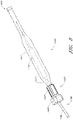
- Figure 1 illustrates one use of the disclosed catheter pump system.
- a distal portion of the pump which can include an impeller assembly 116A, is placed in the left ventricle (LV) of the heart to pump blood from the LV into the aorta.
- the pump can be used in this way to treat patients with a wide range of conditions, including cardiogenic shock, myocardial infarction, and other cardiac conditions, and also to support a patient during a procedure such as percutaneous coronary intervention.
- One convenient manner of placement of the distal portion of the pump in the heart is by percutaneous access and delivery using the Seldinger technique, or other methods familiar to cardiologists. These approaches enable the pump to be used in emergency medicine, a catheter lab and in other non-surgical settings.
- Modifications can also enable the pump 10 to support the right side of the heart.
- Example modifications that could be used for right side support include providing delivery features and/or shaping a distal portion that is to be placed through at least one heart valve from the venous side, such as is discussed in US 6,544,216 ; US 7,070,555 ; and US 2012/0203056 A1 .
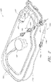
- the catheter assembly 100A may correspond to the disposable portion of the heart pump systems described herein.
- the catheter assembly 100A may include the impeller assembly 116A near a distal portion of the catheter assembly 100A, an elongate body 174A extending proximally from the impeller assembly 116A, an infusion system 195 configured to supply infusate to the catheter assembly 100A, a motor assembly comprising a driven assembly 101 and a drive assembly 103, one or more conduits 302 (e.g., electrical and/or fluid conduits) extending proximally from the motor assembly, and an interface member 300 coupled at a proximal portion of the conduits 302.
- conduits 302 e.g., electrical and/or fluid conduits
- the impeller assembly 116A may be disposed at a distal portion of the catheter assembly 100A.
- the impeller assembly 116A can include an expandable cannula or housing and an impeller with one or more blades. As the impeller rotates, blood can be pumped proximally (or distally in some implementations) to function as a cardiac assist device.
- a priming apparatus 1400 can be disposed over the impeller assembly 116A. As explained herein with reference to Figures 7-8 , the priming apparatus 1400 can be configured to expedite a process of expelling air from the catheter assembly 100A before insertion of the operative device of the catheter assembly into the patient.
- the elongate body 174A extends proximally from the impeller assembly 116A to an infusion system 195 configured to allow infusate to enter the catheter assembly 100A and waste fluid to leave the catheter assembly 100A.
- a catheter body 120A (which also passes through the elongate body 174A) can extend proximally and couple to the driven assembly 101 of the motor assembly.
- the catheter body 120A can pass within the elongate body 174A, such that the elongate body 174A can axially translate relative to the catheter body 120A.
- Axial translation of the elongate body 174A relative to the catheter body 120A can enable the expansion and collapse of the impeller assembly 116A.
- the impeller assembly 116A coupled to a distal portion of the catheter body 120A, may expand into an expanded state by moving the elongate body 174A proximally relative to the impeller assembly 116A.
- the impeller assembly 116A may self-expand into the expanded state in some arrangements. In the expanded state, the impeller assembly 116A is able to pump blood at high flow rates.
- the impeller assembly 116A may be compressed into a collapsed state by advancing a distal portion 170A of the elongate body 174A distally over the impeller assembly 116A to cause the impeller assembly 116A to collapse.
- the catheter body 120A can couple to the driven assembly 101 of the motor assembly.
- the driven assembly 101 can be configured to receive torque applied by the drive assembly 103, which is shown as being decoupled from the driven assembly 101 and the catheter assembly 100A in Figure 2 .
- the drive assembly 103 can be coupled to the driven assembly 101 by engaging a proximal portion of the driven assembly 101 with the drive assembly, e.g., by inserting the proximal portion of the driven assembly 101 into an aperture 105 of the drive assembly 103.
- a drive shaft can extend from the driven assembly 101 through the catheter body 120A to couple to an impeller shaft at or proximal to the impeller assembly 116A.
- the drive assembly 103 can electrically communicate with a controller in a console (see, e.g., Figures 3A-3B ), which can be configured to control the operation of the motor assembly and the infusion system 195 that supplies a flow of infusate in the catheter assembly 100A.
- the impeller of the impeller assembly 116A may thus be rotated remotely by the motor assembly during operation of the catheter pump.
- the motor assembly can be disposed outside the patient. In some arrangements, the motor assembly is separate from the controller or console, e.g., to be placed closer to the patient.
- the motor assembly is part of the controller. In still other arrangements, the motor assembly is miniaturized to be insertable into the patient. Such arrangements allow the drive shaft to be much shorter, e.g., shorter than the distance from the aortic valve to the aortic arch (about 5 cm or less).
- the motor assembly (e . g ., the drive assembly 103 and the driven assembly 101) is in electrical communication with the controller and console by way of the conduits 302, which may include electrical wires.
- the electrical wires may extend from the motor assembly proximally to the interface member 300.
- the controller in the console to electrically communicate with the motor assembly and/or other sensors in the catheter assembly 100A (such as pressure sensors, flow sensors, temperature sensors, bubble detectors, etc.), it can be advantageous to provide a reliable electrical connection between the interface member 300 and the console.
- the removable interface member 300 may include electrical components configured to couple to one or more electrical contacts (sometimes referred to herein as interconnections) in the console.
- the electrical connections may be achieved in a simple, user-friendly manner.
- the electrical connections may be made substantially at the same time, e . g ., substantially simultaneously, as fluid connections are made between the interface member 300 and console.
- the mechanical components rotatably supporting the impeller within the impeller assembly 116A permit high rotational speeds while controlling heat and particle generation that can come with high speeds.
- the infusion system 195 may deliver a cooling and lubricating solution to the distal portion of the catheter assembly 100A for these purposes. As shown in Figure 2 , the infusion system 195 may be in fluid communication with the interface member 300 by way of the conduits 302, which may also include fluid conduits or tubes. Because the catheter assembly 100A may be disposable and/or removable from a console, it can be important to securely couple interface member 300 to the console. Furthermore, it can be important to provide an easy-to-use interface such that users can easily complete fluid connections that remain secure during a treatment procedure.
- Maintaining security of the connection is important because the fluids and signals carried by the conduits 302 enable the impeller to operate in a continuous manner. Stoppage of the pump system may require the catheter assembly 100A to be removed from the patient and replaced in certain circumstances, which may be life-threatening or extremely inconvenient at a minimum.
- the catheter pump system When activated, the catheter pump system can effectively increase the flow of blood out of the heart and through the patient's vascular system.
- the pump can be configured to produce a maximum flow rate (e.g. low mm Hg) of greater than 4 Lpm, greater than 4.5 Lpm, greater than 5 Lpm, greater than 5.5 Lpm, greater than 6 Lpm, greater than 6.5 Lpm, greater than 7 Lpm, greater than 7.5 Lpm, greater than 8 Lpm, greater than 9 Lpm, or greater than 10 Lpm.
- a maximum flow rate e.g. low mm Hg
- the pump can be configured to produce an average flow rate at 8.27kPa (62 mmHg) pressure head of greater than 2 Lpm, greater than 2.5 Lpm, greater than 3 Lpm, greater than 3.5 Lpm, greater than 4 Lpm, greater than 4.25 Lpm, greater than 4.5 Lpm, greater than 5 Lpm, greater than 5.5 Lpm, or greater than 6 Lpm.
- 2013/0303969 entitled “SHEATH SYSTEM FOR CATHETER PUMP,” filed on March 13, 2013 ; US Patent Publication No. 2013/0303830, entitled “IMPELLER FOR CATHETER PUMP,” filed on March 13, 2013 ; US Patent Publication No. 2014/0012065, entitled “CATHETER PUMP,” filed on March 13, 2013 ; and US Patent Publication No. 2014/001686, entitled “MOTOR ASSEMBLY FOR CATHETER PUMP,” filed on March 13, 2013 .
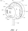
- Figure 3A is a three-dimensional perspective view of a fluid handling system 350 that includes a console 301 and the catheter assembly 100A of Figure 2 .
- the console 301 can provide electrical power, control signals, medical fluids (e . g ., saline) for infusion, and fluid waste extraction to the catheter assembly 100A by way of its interface with the interface member 300.
- medical fluids e . g ., saline
- the removable interface member 300 may be disposed at a proximal portion of the catheter assembly 100A and may be configured to couple to the console 301 at an interface region 303.
- the fluid handling system 350 can be configured to deliver fluids to and/or remove fluids from the catheter assembly 100A.
- saline and/or other medical solutions can lubricate and/or cool components between the motor assembly and the operative device.
- waste fluids can be removed from the catheter assembly 100A using the fluid handling system 350.
- the fluid handling system 350 can include a multilumen catheter body having a proximal end and a distal end.
- the catheter body can include one or more lumens through which medical solutions (e . g ., saline), waste fluids, and/or blood can flow.
- the console 301 includes one or more pump(s) configured to apply positive or negative pressure to the catheter assembly 100A when the catheter assembly 100A is coupled to the console 301 and engages the pump(s).
- the fluid handling system 350 may also be configured to provide electrical communication between the console 301 and the catheter assembly 100A.
- the console can include a controller (e.g., a processor) that is programmed to control and/or manage the operation of the motor assembly.
- the console 301 may also include electrical interfaces configured to supply power to the motor assembly and/or other components that are driven by electrical power when the interface member 300 is coupled to the console 301.
- one or more electrical or electronic sensors may be provided in the catheter assembly 100A and may electrically couple to the console 301 by way of the fluid handling system 350. The arrangements disclosed herein may thereby provide fluid and electrical connections between the catheter assembly 100A and the console 301.
- the fluid handling system 350 provides a removable interface between the catheter assembly 100A and the console 301, which may include various components, including, e.g., one or more pump(s), processors (e.g., the controller), electrical interconnections, etc.
- a user may simply insert a distal portion of the interface member 300 (e.g., including a closure member) along the illustrated Z-direction into an aperture 304 of the interface region 303 until the pump(s) are engaged and the electrical connection(s) are formed. The insertion of the interface member along the Z-direction engages the pump(s) and completes the electrical connection(s) substantially simultaneously.
- the interface member 300 may be secured to the console 301 by engaging a locking device between the interface region 303 and the interface member 300.
- a locking device is by rotating a portion of the interface member 300 relative to another portion of the interface member or relative to the console 301, as explained herein.
- rotation of an outermost structure (opposite the direction Z), sometimes referred to herein as a "cap" relative to the console may engage a locking mechanism configured to mechanically secure the interface member 300 to the console 301 to prevent the interface member 300 from being accidentally disengaged during a treatment procedure.
- the console 301 may also include a user interface 312, which may comprise a display device and/or a touch-screen display.
- the user may operate the percutaneous heart pump system by interacting with the user interface 312 to select, e.g., desired flow rates and other treatment parameters.
- the user may also monitor properties of the procedure on the user interface 312.
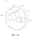
- Figure 3B is a three-dimensional perspective view of the interface region 303 of the console 301 shown in Figure 3A .
- the interface region 303 can include the aperture 304 configured to receive the distal portion of the interface member 303.
- the aperture 304 may include a generally circular cavity shaped and sized to receive a portion of the interface member 300.
- a bubble detector 308 (e.g., an optical sensor in some arrangements) can be positioned at a back wall of the aperture 304.
- the bubble detector 308 may include a recess portion defined by two walls sized and shaped to receive a segment of tubing.
- the bubble detector 308 may monitor the fluid to determine whether or not the fluid includes unwanted matter, e . g ., bubbles of air or other gas. In some arrangements, the bubble detector 308 may measure the amount (number or volume) of bubbles in the fluid passing though the tube segment. It should be appreciated that it can be important to detect bubbles in the treatment fluid to avoid inducing embolisms in the patient.
- the bubble detector 308 may electrically communicate with the controller in the console 301 and can indicate the amount of bubbles in the treatment fluid. The console 301, in turn, can alert the user if there are bubbles in the treatment fluid.
- the interface region 303 also includes one or more pumps, e . g ., peristaltic pumps in some arrangements.
- the peristaltic pumps can be used to pump fluid into or out of the catheter assembly 100A to deliver medical fluids and to remove waste fluids, respectively.
- Such pumps may employ one or more rollers 306 to control delivery of a fluid within a respective tube (see, e.g., pump tube segments 324a, 324b of Figure 4 ).
- the one or more pump rollers 306 can be housed within the console 301.
- two pump rollers 306 are mounted about their rotational axes ( e.g., the Y-direction illustrated in Figure 3B ) at the back wall of the aperture 304.
- the pump rollers 306 can be rotated by a peristaltic pump motor within the console (not shown in Figures 3A-3B ). As explained in more detail herein with respect to Figure 4 below, the rollers 306 can engage pump tube segments 324a, 324b to pump fluid into or out of the catheter assembly 100A.
- the pump rollers 306 may be configured to be received within occlusion bed regions of the interface member 300 (see, e.g., occlusion beds 322a and 322b of Figure 4 ) to pump fluid through the catheter assembly 100A.
- An electrical interconnect 307 can also be provided in the back wall of the aperture 304.
- the electrical interconnect 307 can be configured to provide power to the motor assembly and/or electrical signals or instructions to control the operation of the motor assembly.
- the electrical interconnect 307 can also be configured to receive electrical signals indicative of sensor readings for monitoring pressure, flow rates, and/or temperature of one or more components in the catheter assembly 100A.
- a recessed channel 309 can extend from the bottom of the aperture 304 along the side to the lower edge of the console 301.
- the recessed channel 309 can be shaped and sized to receive one or more of the conduits 302 (e.g., electrical and/or fluid conduits) extending between the interface member 300 and the motor assembly. In one arrangements, all of the conduits 302 can be received within the channel 309 providing a flush side surface when the interface member 300 is disposed in the interface aperture 304.
- the interface region 303 can include a groove 313 sized and shaped to receive a locking mechanism (e . g ., a tab or flange projecting in the X direction) on the interface member 300.
- a locking mechanism e . g ., a tab or flange projecting in the X direction
- a disengaging member 305 includes a spring-loaded release mechanism 310 provided above the aperture 304 and a pin 311 that can be inserted into a hole in the interface member 300 (see, e.g., Figures 5A-5C and the accompanying disclosure below).
- the pin 311 can assist in releasing the interface member 300 relative to the console 301.
- the spring-loaded release mechanism 310 can be pressed to release the pin 311 and unlock the interface member 300 from the console 301.
- the spring-loaded release mechanism 310 can therefore act as a further safety mechanism to ensure that the cassette is not accidentally disengaged by the user.
- Figure 4 is a three-dimensional perspective view of the interface member 300, according to one arrangement.
- the interface member 300 comprises a body that is shaped and sized to fit into the interface region 303 of the console 301. As shown in Figure 4 , the interface member 300 can have a substantially circular profile, and is sometimes referred to as a puck.
- the interface member 300 can include an outer body 333 operably coupled to a manual interface 320, sometimes referred to as a cap.
- the manual interface 320 is generally palm-sized so that a user can receive it in their hand and operate it comfortably, e . g ., with finger pressure on the outer rim of the cap.
- One or more occlusion beds are formed or provided at the interface between the interface member 300 and the console 301, e.g., in or on the interface member 300.
- first and second occlusion beds 322a and 322b are formed in the interface member 300.
- the occlusion beds 322a, 322b include arcuate recessed regions formed in the interface member 300.
- the interface member 300 further includes first and second pump tube segments 324a, 324b positioned along the occlusion beds 322a, 322b formed in the interface member 300.
- the pump rollers 306 engage with the interface member 300 and compress the tube segment(s) 324a, 324b against the occlusion bed(s) 322a, 322b, respectively.
- the pump motor(s) in the console 301 rotate the rollers 306, fluid flows into uncompressed portions of the tube segment(s) 324a, 324b and continues flowing throughout the catheter assembly 100A.
- the fluid may be pumped into or out of the catheter assembly 100A by way of the conduits 302 extending from the interface member 300 to the motor assembly and distally beyond the motor assembly.
- the body of the interface member 300 (e.g., the outer body 333 and/or an inner body, such as inner body 339 illustrated in Figures 5B-5C ) can be formed with precise tolerances (e . g ., molded from a unitary structure in some implementations) such that when the interface member 300 is inserted into the console 301, the pump rollers 306 precisely and automatically engage with the tube segments 324a, 324b and occlusion beds 322a, 322b to reliably occlude the tube segments 324a, 324b and pump fluids through the catheter assembly 100A.
- the pump in the console 301 can automatically engage the interface member 300.
- the gap between the rollers 306 and the occlusion beds 322a, 322b can be less than about two wall thicknesses of the tube segments 324a, 324b in some arrangements, such that the tubes 324a, 324b can be effectively occluded.
- the pump can be engaged by simply inserting the interface member 300 into the console 301. There is no need to separately activate the pump.
- the dimensions of the interface member 300 may be selected such that the occlusion bed(s) 322a, 322b automatically engages the respective pump rollers 306 upon insertion of the interface member 300 into the console 301.
- the interface member 300 and interface region 303 provide an easy-to-use, quick connection of the tubing segments to one or more respective rollers 306. Moreover, the components can be manufactured easily and cost-effectively because only certain components require tight tolerances and the interface of member 300 to region 303 is essentially self-aligning. The interface also eliminates any need to engage the pump through a second mechanism or operator step, streamlining operation of the heart pump and simplifying the engagement of the catheter assembly 100A to the console 301.
- the simplified engagement mechanisms disclosed herein can be advantageous because there is only a minimal applied force against the pole, which prevents the pole from rolling or tipping when the pump is engaged.
- the pump tube segments 324a, 324b are mounted on the interface body 300 near or in the respective occlusion beds 322a, 322b. As illustrated, the first and second pump tube segments 324a, 324b are configured to engage with the pump rollers 306 in the console 301, as explained above.
- the first and second pump tube segments 324a, 324b can have an arcuate shape (which may be pre-formed in various arrangements) that generally conforms to the curved shape of each respective occlusion bed 322a, 322b.
- the pump rollers 306 within the console 301 can thereby be positioned within the occlusion beds 322a, 322b to compress the tube segments 324a, 324b against the wall of the occlusion beds 322a, 322b.
- a bubble detector tube segment 326 can also be mounted in or on the interface member 300 and can be configured to engage with or be positioned adjacent to the bubble detector 308 illustrated in Figure 3B .
- the bubble detector tube segment 326 can be any suitable shape.
- the bubble detector tube segment can be substantially straight and can be sized and shaped to be received by the bubble detector 308 within the console 301.
- the bubble detector 308 (which may be an optical sensor) can be used to detect air bubbles in the treatment or lubricating fluid being supplied to the patient.
- the tube segments can be fluidly connected to the remainder of the catheter assembly 100A, including, e . g ., one or more lumens of the catheter body, by way of the conduits 302.
- the removable interface member 300 allows fluid to be pumped into and out of the patient within a controlled system, e . g ., such that the fluids within the catheter assembly 100A can be pumped while maintaining a sterile environment for the fluids.
- the volume of medical solution into the catheter body can be equal to, or can exceed by a minimum amount, the volume of medical solution out of the catheter body to assure that blood does not enter a blood-free portion of the heart pump.
- one or more electrical contacts 328 can be provided in the interface member 300.
- the electrical contacts 328 can be any suitable electrical interface configured to transmit electrical signals between the console 301 and the catheter assembly 100A (e.g., the motor assembly and/or any suitable sensors).
- the electrical contacts 328 can be configured to electrically couple to the electrical interconnect 307 disposed in the console 301. Electrical control signals and/or power may be transmitted between the console 301 and the catheter assembly 100A by way of the electrical connection between the electrical contacts 328 and the electrical interconnect 307.
- the electrical connection between the electrical contacts 328 and the electrical interconnect 307 may be formed or completed when the interface member 300 is inserted into the interface region 303 of the console 301.
- the electrical connection between the electrical contacts 328 and the electrical interconnect 307 may be formed substantially simultaneously with the fluid connection ( e . g ., the engagement of the pump) when the interface member 300 is inserted into the interface region 303.
- the electrical connection can be formed by inserting electrical pins from the electrical contacts 328 into corresponding holes of the electrical interconnect 307 of the console 301, or vice versa.
- the manual interface 320 can be mechanically coupled to a proximal portion of the outer body 333 and may be configured to rotate relative to the outer body 333 in a constrained manner, as explained below relative to Figures 5A-5C .
- the outer body 333 can include one or more locking apertures 331 configured to receive locking tabs 332 that are configured to lock the manual interface 320 relative to the console 301.
- the outer body 333 may include a pin hole 321 sized and shaped to receive the pin 311 illustrated in Figure 3B to releasably couple the removable interface member 300 relative to the console 301.
- the configuration of the pump rollers, occlusion bed, and tubing can be modified depending on the application.
- the configuration may be modified to provide easier access for service and repair.
- the pump rollers may be disposed external to the console.
- the rollers may be fixed.
- the rollers may be configured to rotate, translate, or both.
- the rollers and/or the occlusion bed may be positioned on a base that is configured to move.
- the console-cassette interface can include a positive pressure interface to pump fluid (e.g., saline) into the patient's vasculature and a negative pressure interface to pump fluid (e.g., waste fluid) out of the patient's vasculature.
- pump fluid e.g., saline
- negative pressure interface to pump fluid (e.g., waste fluid) out of the patient's vasculature.
- the interface member 300 advantageously can be fully engaged with the console 301 by simply inserting it into a correspondingly shaped aperture 304 in the housing of the console 301.
- a locking mechanism in the interface member 300 can be provided for additional security, which can be particularly useful for patient transport and other more dynamic settings. For example, it is desirable to ensure that the catheter assembly 100A is secured to the console 301 during the entire procedure to ensure that the procedure is not disrupted due to accidental disengagement of the interface member 300 from the console 301.
- the locking mechanism can be disposed between the console 301 and the interface member 300 and can be configured to be engaged by a minimal movement of an actuator.
- the manual interface 320 can be provided to cause engagement of a locking device by a small rotational turn of the manual interface 320 relative to the console 301.
- Figure 5A is a three-dimensional perspective view of the manual interface 320.
- the manual interface 320 can include or be coupled with an internal cam 335.
- the cam 335 can include one or more protruding lobes, such as lobes 336a and 336b. Further, the cam 335 can include a recessed region 337 recessed inwardly relative to the lobes 336a, 336b.
- the cam 335 can also include a stepped region 338 which can enable the interface member 300 to be locked and unlocked relative to the console 301, as explained herein.
- Figure 5B is a three-dimensional perspective view of an interface member 300A in an unlocked configuration
- Figure 5C is a three-dimensional perspective view of an interface member 300B in a locked configuration.
- the interface members 300A, 300B of Figures 5B and 5C are illustrated without the outer body 333, which has been hidden in Figures 5B and 5C for purposes of illustration.
- the components of Figures 5B and 5C are the same as or similar to the components illustrated with respect to Figure 4 .
- the interface members 300A, 300B can include an inner body 339 that can be disposed within the outer body 333 shown in Figure 4 .
- the occlusion beds 322a, 322b can be formed in the inner body 339 of the interface member 300A, 300B, as shown in Figures 5B-5C ; however, in other arrangements, the occlusion beds 322a, 322b may be formed in the outer body 333 or other portions of the interface member 300A, 300B.
- an electrical component 340 can be disposed in a recess or other portion of the inner body 339. Additional details regarding the electrical component 340 are explained below with respect to Figures 6A-6B .
- the inner body 339 of the interface member 300A, 300B can further include a protrusion 330 that includes the tab 332 at a distal portion of the protrusion 330.
- the protrusion 330 can be disposed in or near the recess 337 of the cam 335 in the manual interface 320.
- the cam 335 may therefore not contact or apply a force against the protrusion 330 when the interface member 300A is in the unlocked configuration, as shown in Figure 5B .
- the interface member 300 can be locked into place by rotating the manual interface 320 relative to the inner body 339 and the console 301, e.g., rotated in the A-direction illustrated in Figure 5B .
- the internal cam 335 is also rotated within the interface member 300A, 300B.
- the lobes 336a, 336b of the cam 335 can engage with the one or more protrusions 330 of the inner body 339 and can push the protrusions 330 outwardly relative to the inner body 339.
- the tabs 332 may extend outwardly through the locking apertures 331 formed on the outer body 333.
- each of the tabs 332 can lock into the groove(s) 313 in the console 301 ( see Figure 3B ) to secure the interface member 300B to the console 301.
- the tab 332 in the unlocked position, can be substantially flush with the outer surface of the interface member 300A, and in the locked position, the tab 332 can extend through the locking aperture 331 and lock into the grooves 313 in the console 301.
- the protrusion 330 can be a cantilevered protrusion from the inner body 339. As mentioned above, it can be important to maintain tight tolerances between the occlusion beds 322a, 322b, which is also formed in the interface member, and the pump rollers 306 when the interface member 300 engages with the console 301. Because the occlusion beds 322a, 322b may be formed in the same body as the cantilevered protrusions 330, conventional manufacturing processes, such as molding processes, can be used to manufacture the interface member 300 (e.g., the outer body 333 and/or the inner body 339) according to precise dimensions.
- the protrusion(s) 330, tab(s) 332 and the occlusion bed(s) 322a, 322b can be made within tight dimensional tolerances, and the tab(s) 332 and/or protrusion(s) 330 can be positioned relative to the occlusion bed(s) 322a, 322b with very high precision such that when the interface member 300 is engaged with the console 301, the tube segments 324a, 324b are optimally occluded.
- the interface member 300 can be locked by rotating the manual interface 320 on the interface member 300, only minimal forces are applied to the console 301. This enhances the advantages of minimizing disruption of a mobile cart or IV pole to which the system may be coupled.
- the disengaging member 305 of the console 301 can be configured to disengage and unlock the interface member 300 from the console 301.
- the pin 311 may be spring-loaded such that when the interface member 300A is in the unlocked configuration, the pin 311 extends through the pin hole 321 of the outer body 333 but only contacts a side surface of one of the lobes 336b of the cam 335. Thus, in the unlocked configuration of the interface member 300A, the pin 311 may simply slide along the cam surface, permitting rotation of the manual interface 320 relative to the pin 311 and the console 301.
- the pin 311 can engage with the stepped region 338 of the internal cam 335, e.g., the spring-biased pin 311 can extend into the stepped region 338 or shoulder of the cam 335.
- the pin 311 prevents the cam 335 from rotating from the locked configuration to the unlocked configuration.
- a user can disengage the cassette by pressing the spring-loaded release mechanism 310 to release the spring and remove the pin 311 from the stepped region 338.
- the pin 311 can thereby be disengaged from the stepped region 338, and the internal cam 335 can rotate back into the unlocked position.
- the tab 332 can be withdrawn from the groove 313 in the console 301 to unlock the interface member 300.
- Figure 6A is a three-dimensional perspective view of a first side of the electrical component 340 illustrated in Figures 5B and 5C .
- Figure 6B is a three-dimensional perspective view of a second, opposite side of the electrical component 340 of Figure 6A .
- the electrical component 340 may be disposed in a recess of the interface member 300.
- the electrical component 340 can be any suitable electrical or electronic component, including, e.g., a printed circuit board (PCB) configured to provide an electrical interface between various components in the catheter assembly 100A and the console 301.
- the electrical component 340 can form an electrical interface between the interface member 300 and the console 301 to provide electrical communication between the console 301 and the catheter assembly 100A (such as the motor assembly and/or various sensors).
- the electrical component 340 of the interface member 300 can include the one or more electrical contacts 328 configured to mate with the corresponding electrical interconnect 307 in the console 301.
- the electrical contacts 328 and/or the electrical interconnect 307 can be, for example, nine-pin electrical interconnects, although any suitable interconnect can be used.
- the motor assembly that drives the operative device ( e . g ., impeller) of the catheter pump can be electrically connected to the interface member 300 by way of one or more electrical cables, e.g., the conduits 302.
- the console 301 can be coupled to a power source, which can drive the catheter pump motor assembly by way of the interface member's contacts 328 and the electrical conduits 302 connecting the interface member 300 to the motor assembly.
- the electrical component 340 can also include communications interconnects configured to relay electrical signals between the console 301 and the catheter pump motor assembly or other portions of the catheter assembly 100A.
- a controller within the console 301 (or interface member) can send instructions to the catheter pump motor assembly via the electrical component 340 between the console 301 and the interface member 300.
- the electrical component 340 can include interconnects for sensors (such as pressure or temperature sensors) within the catheter assembly 100A, including sensors at the operative device.
- the sensors may be used to measure a characteristic of the fluid in one or more of the tubes ( e . g ., saline pressure).
- the sensors may be used to measure an operational parameter of the system ( e . g ., ventricular or aortic pressure).
- the sensors may be provided as part of an adjunctive therapy.
- the electrical component 340 within the interface member 300 can be used to electrically couple the cable (and the motor assembly, sensors, etc.) with the corresponding interconnects 307 in the console 301.
- one or more internal connectors 346 and 348 on the second side of the electrical component 340 may provide electrical communication between the contacts 328 (configured to couple to the interconnects 307 of the console 301) and the catheter assembly 100.
- electrical cables e.g., the conduits 302
- the internal connectors 346, 348 may electrically communicate with the contacts 328 on the first side of the electrical component 340, which in turn communicate with the interconnects 307 of the console 301.
- the electrical component 340 is fluidly sealed to prevent the internal electronics from getting wet. This may be advantageous in wet and/or sterile environments. This may also advantageously protect the electronics in the event one of the fluid tubes leaks or bursts, which is a potential risk in high pressure applications.
- the electrical component 340 can include various electrical or electronic components mounted thereon.
- two pressure sensors 344a, 344b can be mounted on the electrical component 340 to detect the pressure in the pump tube segments 324a, 324b.
- the pressure sensors 344a, 344b may be used to monitor the flow of fluids in the tube segments 324a, 324b to confirm proper operation of the heart pump, for example, confirming a proper balance of medical solution into the catheter body and waste out of the catheter body.
- Various other components such as a processor, memory, or an Application-Specific Integrated Circuit (ASIC), can be provided on the circuit board.
- ASIC Application-Specific Integrated Circuit
- respective pressure sensor ASICs 345a, 345b can be coupled to the pressure sensors 344a, 344b to process the signals detected by the pressure sensors 344a, 344b.
- the processed signals may be transmitted from the ASICs 345a, 345b to the console 301 by way of internal traces (not shown) in the PCB and the contacts 328.
- the infusate system 1300 can be configured to supply treatment and/or lubricating fluids to the operative device of the catheter assembly (e . g ., an impeller assembly 116), and to remove waste fluid from the assembly.
- an elongate body 174 can be slidably disposed over a catheter body 120, such that there may be gaps or channels between the outer surface of the catheter body 120 and the inner surface of the elongate body 174. Such gaps or channels can contain air pockets harmful to the patient during a medical procedure.
- the lumen or lumens extending within the catheter body 120 also can contain air pockets harmful to the patient. Thus, it is desirable to expel air from both the lumens within catheter body 120 and the gaps or channels disposed between the elongate body 174 and the catheter body 120 before conducting a treatment procedure.
- the system 1300 of Figure 7 may be configured to supply fluid to the catheter assembly during treatment, to remove waste fluid during treatment, and/or to expel air from the elongate body 174, e.g., between the inner surface of the elongate body 174 and the outer surface of the catheter body 120 before treatment.
- an interface member 1313 (similar to or the same as the interface member 300 described herein, in some aspects) may be provided to connect various components of the catheter assembly, as discussed herein.
- An outer sheath tubing 1303a can extend from a fluid reservoir 1305 to a luer 102 configured to be coupled to an infusate device.
- the outer sheath tubing 1303a can be configured to deliver fluid to the outer sheath, e.g., the space between the elongate body 174 and the catheter body 120.
- the fluid reservoir 1305 may optionally include a pressure cuff to urge fluid through the outer sheath tubing 1303a. Pressure cuffs may be particularly useful in fluid delivery arrangements using gravity-induced fluid flow.
- the luer 102 can be configured to deliver infusate or other priming fluid to the elongate body 174 to expel air from the elongate body 174 as described herein in order to "prime" the system 1300.
- a pressure sensor 1309a which may be disposed on a motor housing 1314, can be coupled to the outer sheath tubing 1303a to measure the pressure of the infusate or priming fluid flowing through the outer sheath tubing 1303a and into the luer 102.
- the motor housing 1314 illustrated in Figure 7 may be the same as or similar to the motor assembly described above with reference to Figure 2 , for example, when the drive assembly 103 is coupled to the driven assembly 101.
- inner catheter tubing 1303b can extend between the motor housing 1314 and the fluid reservoir 1305, by way of a T-junction 1320.
- the inner catheter tubing 1303b can be configured to deliver fluid to the lumen or lumens within catheter body 120 during treatment and/or to expel air from the catheter 120 and prime the system 1300.
- a pumping mechanism 1306a such as a roller pump for example, can be provided along inner catheter tubing 1303b to assist in pumping the infusate or priming fluid through the system 1300.
- the roller pump can be a peristaltic pump in some arrangements.
- an air detector 1308 can be coupled to the inner catheter tubing 1303b and can be configured to detect any air or bubbles introduced into the system 1300.
- a pressure sensor 1309b can couple to inner catheter tubing 1303b to detect the pressure of the fluid within the tubing.
- a filter 1311 can be employed to remove debris and other undesirable particles from the infusate or priming fluid before the catheter body 120 is infused or primed with liquid.
- the air detector 1308, the pressure sensor 1309b, and the pumping mechanism 1306a can be coupled to the interface member 1313 described above (such as the interface member 300).
- One or more electrical lines 1315 can connect the motor housing 1314 with the cassette 1313.
- the electrical lines 1315 can provide electrical signals for energizing a motor or for powering the sensor 1309a or for other components.
- infusate or priming fluid can be introduced at the proximal end of the catheter assembly. The fluid can be driven distally to drive air out of the catheter body 120 to prime the system.
- a waste fluid line 1304 can fluidly connect the catheter body 120 with a waste reservoir 1310.
- a pressure sensor 1309c which may be disposed on or coupled to the interface member 1313, can measure the pressure of the fluid within the waste fluid line 1304.
- a pumping mechanism 1306b such as a roller pump, for example, can be coupled to the interface member 1313 and can pump the waste fluid through the waste fluid line 1304 to the waste reservoir 1310.
- Figure 8 is an enlarged view of the priming apparatus 1400 shown in Figure 2 .
- the priming apparatus 1400 may be disposed over the impeller assembly 116A near the distal end 170A of the elongate body 174A.
- the priming apparatus 1400 can be used in connection with a procedure to expel air from the impeller assembly 116A, e.g., any air that is trapped within the housing or that remains within the elongate body 174A near the distal end 170A.
- the priming procedure may be performed before the pump is inserted into the patient's vascular system, so that air bubbles are not allowed to enter and/or injure the patient.
- the priming apparatus 1400 can include a primer housing 1401 configured to be disposed around both the elongate body 174A and the impeller assembly 116A.
- a sealing cap 1406 can be applied to the proximal end 1402 of the primer housing 1401 to substantially seal the priming apparatus 1400 for priming, i.e., so that air does not proximally enter the elongate body 174A and also so that priming fluid does not flow out of the proximal end of the housing 1401.
- the sealing cap 1406 can couple to the primer housing 1401 in any way known to a skilled artisan.
- the sealing cap 1406 is threaded onto the primer housing by way of a threaded connector 1405 located at the proximal end 1402 of the primer housing 1401.
- the sealing cap 1406 can include a sealing recess disposed at the distal end of the sealing cap 1406.
- the sealing recess can be configured to allow the elongate body 174A to pass through the sealing cap 1406.
- the priming operation can proceed by introducing fluid into the sealed priming apparatus 1400 to expel air from the impeller assembly 116A and the elongate body 174A.
- Fluid can be introduced into the priming apparatus 1400 in a variety of ways.
- fluid can be introduced distally through the elongate body 174A into the priming apparatus 1400.
- an inlet such as a luer, can optionally be formed on a side of the primer housing 1401 to allow for introduction of fluid into the priming apparatus 1400.
- a gas permeable membrane can be disposed on a distal end 1404 of the primer housing 1401.
- the gas permeable membrane can permit air to escape from the primer housing 1401 during priming.
- the priming apparatus 1400 also can advantageously be configured to collapse an expandable portion of the catheter assembly 100A.
- the primer housing 1401 can include a funnel 1415 where the inner diameter of the housing decreases from distal to proximal.
- the funnel may be gently curved such that relative proximal movement of the impeller housing causes the impeller housing to be collapsed by the funnel 1415.
- the distal end 170A of the elongate body 174A can be moved distally relative to the collapsed housing.
- the catheter assembly 100A can be removed from the priming housing 1400 before a percutaneous heart procedure is performed, e.g., before the pump is activated to pump blood.
- the arrangements disclosed herein may be implemented such that the total time for infusing the system is minimized or reduced.
- the time to fully infuse the system can be about six minutes or less.
- the infusate time can be less than 5 minutes, less than 4 minutes, or less than 3 minutes.
- the total time to infuse the system can be about 45 seconds or less. It should be appreciated that lower infusate times can be advantageous for use with cardiovascular patients.
- the heart pump is inserted in a less invasive manner, e.g., using techniques that can be employed in a catheter lab.
- the catheter assembly 100A Prior to insertion of the catheter assembly 100A of the heart pump, various techniques can be used to prepare the system for insertion.
- the catheter assembly 100A can be primed to remove gas that could be contained therein prior to any method being performed on the patient.
- This priming technique can be performed by placing a distal portion of the catheter assembly 100A in a priming vessel, such as the apparatus 1400. Thereafter, a media is delivered into the catheter assembly 100A under pressure to displace any potentially harmful matter, e.g., air or other gas, out of the catheter assembly 100A.
- the apparatus 1400 is filled with a biocompatible liquid such as saline.
- a biocompatible liquid such as saline is caused to flow distally through the catheter assembly 100 to displace air in any of the cavities formed therein, as discussed above.
- a pressure or flow rate for priming can be provided that is suitable for priming, e.g., a pressure or flow rate that is lower than the operational pressure or flow rate.
- the biocompatible liquid is pushed under positive pressure from the proximal end through the catheter assembly 100A until all gas is removed from voids therein.
- One technique for confirming that all gas has been removed is to observe the back-pressure or the current draw of the pump.
- the priming apparatus 1400 can be configured to permit gas to escape while preventing saline or other biocompatible liquid from escaping. As such, the back-pressure or current draw to maintain a pre-selected flow will change dramatically once all gas has been evacuated.
- the priming apparatus 1400 can include a source of negative pressure for drawing a biocompatible liquid into the proximal end of the catheter assembly 100A.
- Applying a negative pressure to the priming apparatus 1400 can have the advantage of permitting the catheter assembly 100A to be primed separate from the pumps that are used during operation of the heart pump.
- the priming can be done in parallel with other medical procedures on the patient by an operator that is not directly working on the patient.
- a positive pressure pump separate from the pump that operates the heart pump can be used to prime under positive pressure applied to the proximal end.
- Various priming methods may also be expedited by providing a separate inlet for faster filling of the enclosed volume of the priming apparatus 1400.
- a further aspect of certain methods of preparing the catheter assembly 100A for insertion into a patient can involve collapsing the impeller housing 116A.
- the collapsed state of the impeller housing 116A reduces the size, e.g., the crossing profile, of the distal end of the system. This enables a patient to have right, left or right and left side support through a small vessel that is close to the surface of the skin, e.g., using catheter lab-type procedures.
- the priming apparatus 1400 has a funnel configuration that has a large diameter at a distal end and a smaller diameter at a proximal end. The funnel gently transitions from the large to the small diameter.
- the impeller housing 116A can be collapsed by providing relative movement between the priming apparatus 1400 and the impeller housing 116A.
- the priming housing 1400 can be held in a fixed position, e . g ., by hand, and the catheter assembly 100A can be withdrawn until at least a portion of the impeller assembly 116A is disposed in the small diameter segment of the priming apparatus 1400.
- the elongate body 174A of the sheath assembly can be advanced over the collapsed impeller assembly 116A.
- the catheter assembly 100A is held still and the priming apparatus 1400 is slid distally over the impeller assembly 116A to cause the impeller assembly 116A to collapse. Thereafter, relative movement between the elongate body 174A and the impeller assembly 116A can position the distal end 170A of the elongate body 174A over the impeller assembly 116A after the catheter assembly 100A has been fully primed.
Description
- This application is directed to pumps for mechanical circulatory support of a heart. In particular, this application is directed to a console and controller for a catheter pump and a fluid handling system configured to convey and remove fluids to and from the catheter pump.
- Heart disease is a major health problem that has a high mortality rate. Physicians increasingly use mechanical circulatory support systems for treating heart failure. The treatment of acute heart failure requires a device that can provide support to the patient quickly. Physicians desire treatment options that can be deployed quickly and minimally-invasively.
- Intra-aortic balloon pumps (IABP) are currently the most common type of circulatory support devices for treating acute heart failure. IABPs are commonly used to treat heart failure, such as to stabilize a patient after cardiogenic shock, during treatment of acute myocardial infarction (MI) or decompensated heart failure, or to support a patient during high risk percutaneous coronary intervention (PCI). Circulatory support systems may be used alone or with pharmacological treatment.
- In a conventional approach, an IABP is positioned in the aorta and actuated in a counterpulsation fashion to provide partial support to the circulatory system. More recently, minimally-invasive rotary blood pumps have been developed in an attempt to increase the level of potential support (i.e., higher flow). A rotary blood pump is typically inserted into the body and connected to the cardiovascular system, for example, to the left ventricle and the ascending aorta to assist the pumping function of the heart. Other known applications pumping venous blood from the right ventricle to the pulmonary artery for support of the right side of the heart. An aim of acute circulatory support devices is to reduce the load on the heart muscle for a period of time, to stabilize the patient prior to heart transplant or for continuing support.
- There is a need for improved mechanical circulatory support devices for treating acute heart failure. Fixed cross-section ventricular assist devices designed to provide near full heart flow rate are either too large to be advanced percutaneously (e.g., through the femoral artery without a cutdown) or provide insufficient flow.
- There is a need for a pump with improved performance and clinical outcomes. There is a need for a pump that can provide elevated flow rates with reduced risk of hemolysis and thrombosis. There is a need for a pump that can be inserted minimally-invasively and provide sufficient flow rates for various indications while reducing the risk of major adverse events. In one aspect, there is a need for a heart pump that can be placed minimally-invasively, for example, through a 5.00mm diameter (15FR) or 4.00mm diameter (12FR) incision. In one aspect, there is a need for a heart pump that can provide an average flow rate of 4 Lpm or more during operation, for example, at 8.27kPa (62 mmHg) of head pressure. While the flow rate of a rotary pump can be increased by rotating the impeller faster, higher rotational speeds are known to increase the risk of hemolysis, which can lead to adverse outcomes and in some cases death. Accordingly, in one aspect, there is a need for a pump that can provide sufficient flow at significantly reduced rotational speeds.
- Furthermore, in various catheter pump systems, it can be important to provide fluids to an operative device of a catheter assembly (e.g., for lubrication of moving parts and/or treatment fluids to be delivered to the patient), and to remove waste fluids from the patient's body. A controller may be provided to control the flow into and out of the catheter assembly. It can be advantageous to provide improved mechanisms for engaging the catheter assembly with the controller, which may be housed in a console.
- Additionally, there is a need to reduce the time to implantation and treatment. In the case of therapy for acute heart failure in particular, the time it takes to start therapy can be critical to survival and good outcomes. For example, a difference of several minutes can be the difference between recovery and permanent brain damage for patients suffering myocardial infarction or cardiogenic shock. Accordingly, a continuing need exists to provide pump systems that can be set up, primed, and inserted faster, easier, and more effectively.
- These and other problems are overcome by the invention described herein.
- Nonetheless, in connection with a different medical field,
WO 02/081919 - In
US 2010/047099 there is described a micropump that includes: a tube unit which includes a tube having elasticity and a circular-arc-shaped part and a tube guide frame for holding the tube; a control unit which has a plurality of fingers extending from the center of the circular-arc shape of the tube in the radial directions, a cam for sequentially pressing the plural fingers from the inlet side to the outlet side of the tube, a drive unit for giving rotation force to the cam, a control circuit unit for controlling operation of the drive unit, a device frame for holding the plural fingers, the cam, the drive unit, and the control circuit unit; a reservoir communicating with an inlet port of the tube; and a power source for supplying power to the control circuit unit, wherein the tube unit is detachably attached to the control unit substantially in the horizontal direction with respect to the rotation surface of the cam and attached to the inside of a space produced by the device frame. - According to the present invention there is provided a fluid handling system comprising the features of claim 1.
- The fluid handling system includes a console housing. The console housing includes one or more pumps, and a controller configured to operate the pump(s). The system further includes a catheter assembly. The catheter assembly includes a catheter body having a proximal portion and an operative device at a distal portion. An infusion system is in fluid communication with the proximal portion of the catheter body. The infusion system includes an interface member configured to be separate from the console housing in a first state and to at least partially secure the infusion system to the console housing in a second state. Upon engagement of the interface member with the console housing in the second state, the infusion system is operably engaged with the pump(s). First and second occlusion beds are formed in the interface member. The first occlusion bed includes a first arcuate recessed region formed in the interface member and the second occlusion bed include a second arcuate recessed region formed in the interface member. The interface member further includes first and second pump tube segments positioned along the occlusion beds formed in the interface member. In the second state, upon engagement of the interface member with the console housing, the one or more pumps engage with the interface member and compress the first and second pump tube segments against the first and second occlusion beds, respectively.
- Although not claimed, there is also described a method for operably coupling an infusion system to a console housing. The method comprises positioning an interface member of the infusion system in an interface aperture of the console housing. The interface member comprises an occlusion bed, a tube segment mounted on the interface body near the occlusion bed, and an electrical component. The method further comprises inserting the interface member through the interface aperture until a pump roller of the console housing compresses the tube segment against the occlusion bed and until an electrical interconnect of the console housing is electrically coupled to the electrical component of the interface body.
- Again, although not claimed, there is also described a method for priming a catheter assembly. The catheter assembly includes an elongate body and an operative device. The method comprises inserting the operative device of the catheter assembly into a priming vessel. The method further comprises securing a proximal portion of the priming vessel to a distal portion of the elongate body, such that the elongate body is in fluid communication with the priming vessel. Fluid is delivered through the elongate body and the priming vessel to expel air within the catheter assembly.
- A more complete appreciation of the subject matter of this application and the various advantages thereof can be realized by reference to the following detailed description, in which reference is made to the accompanying drawings in which:
-
Figure 1 is a schematic view of an operative device of a catheter assembly in position within the anatomy for assisting the left ventricle. -
Figure 2 is a three-dimensional perspective view of a catheter assembly. -
Figure 3A is a three-dimensional perspective view of a fluid handling system that includes a console and catheter assembly. -
Figure 3B is a three-dimensional perspective view of an interface region of the console shown inFigure 3A . -
Figure 4 is a three-dimensional perspective view of an interface member. -
Figure 5A is a three-dimensional perspective view of a cap. -
Figure 5B is a three-dimensional perspective view of an interface member in an unlocked configuration. -
Figure 5C is a three-dimensional perspective view of an interface member in a locked configuration. -
Figure 6A is a three-dimensional perspective view of a first side of an electrical component. -
Figure 6B is a three-dimensional perspective view of a second, opposite side of the electrical component ofFigure 6A . -
Figure 7 is a schematic diagram of an infusate system. -
Figure 8 is an enlarged view of a priming apparatus shown inFigure 2 . - More detailed descriptions of various components for heart pumps useful to treat patients experiencing cardiac stress, including acute heart failure, are set forth below.
- This application is directed to fluid handling systems that are configured to control and/or manage fluid and electrical pathways in a catheter assembly, such as a catheter assembly of a percutaneous heart pump system. In particular, the disclosed percutaneous heart pump systems may include a catheter assembly and a console that includes a controller configured to control the fluid and electrical pathways that pass through the catheter assembly. Some of the disclosed arrangements generally relate to various configurations for coupling and engaging the catheter assembly with the console. For example, the console may be configured to control the flow rate of the pump and to monitor various physiological parameters and pump performance through the various electrical and fluid pathways of the catheter assembly. In some arrangements, the catheter assembly may be disposable, such that the catheter assembly can be discarded after use, while the console and controller are reusable. In arrangements with a reusable console and a disposable catheter assembly (or, indeed, in any arrangements where consoles and catheter assemblies may be coupled), it can be desirable to provide an effective interface between the catheter assembly and the console that completes the various fluid and electrical connections between the catheter assembly and the console.
- In particular, it can be advantageous to provide an interface member at a proximal portion of the catheter assembly that is removably engageable with the console. Furthermore, to enhance usability and to minimize mistakes in making the connections, it can be important to make the interface easy to use so that users can easily connect the catheter assembly to the console before use and easily remove the catheter assembly from the console after use. Moreover, it can be important that the interface provides a secure connection between the interface member of the catheter assembly and an interface region of the console to ensure that the catheter assembly remains connected to the console uninterrupted during treatment.
- As explained herein, one example of a catheter assembly is used in a percutaneous heart pump system having an operative device (e.g., an impeller assembly) that is configured to assist the patient's heart in pumping blood. The heart pump system may be configured to at least temporarily support the workload of the left ventricle in some applications. The exemplary heart pump can be designed for percutaneous entry through the femoral artery to a patient's heart. In particular, the exemplary impeller assembly can include a collapsible impeller and cannula, which can be inserted into the patient's vasculature at a catheter size of less than 4.33mm in diameter (13 FR), for example, about 4.17mm in diameter (12.5 FR) in some arrangements. During insertion through the patient's vascular system to the heart, a sheath may maintain the impeller and cannula assembly in a stored configuration. When the impeller assembly is positioned in the left ventricle (or another chamber of a patient's heart), the impeller and cannula can expand to a larger diameter, for example to a catheter size of about 8.00mm in diameter (24 FR) when the sheath is removed from the impeller assembly. The expanded diameter of the impeller and cannula may allow for the generation of higher flow rates.
- For example,
Figure 1 illustrates one use of the disclosed catheter pump system. A distal portion of the pump, which can include animpeller assembly 116A, is placed in the left ventricle (LV) of the heart to pump blood from the LV into the aorta. The pump can be used in this way to treat patients with a wide range of conditions, including cardiogenic shock, myocardial infarction, and other cardiac conditions, and also to support a patient during a procedure such as percutaneous coronary intervention. One convenient manner of placement of the distal portion of the pump in the heart is by percutaneous access and delivery using the Seldinger technique, or other methods familiar to cardiologists. These approaches enable the pump to be used in emergency medicine, a catheter lab and in other non-surgical settings. Modifications can also enable the pump 10 to support the right side of the heart. Example modifications that could be used for right side support include providing delivery features and/or shaping a distal portion that is to be placed through at least one heart valve from the venous side, such as is discussed inUS 6,544,216 ;US 7,070,555 ; andUS 2012/0203056 A1 . - Turning to
Figure 2 , a three-dimensional perspective view of acatheter assembly 100A is disclosed. Thecatheter assembly 100A may correspond to the disposable portion of the heart pump systems described herein. For example, thecatheter assembly 100A may include theimpeller assembly 116A near a distal portion of thecatheter assembly 100A, anelongate body 174A extending proximally from theimpeller assembly 116A, aninfusion system 195 configured to supply infusate to thecatheter assembly 100A, a motor assembly comprising a drivenassembly 101 and adrive assembly 103, one or more conduits 302 (e.g., electrical and/or fluid conduits) extending proximally from the motor assembly, and aninterface member 300 coupled at a proximal portion of theconduits 302. - Moving from the distal end of the
catheter assembly 100A ofFigure 2 to the proximal end, theimpeller assembly 116A may be disposed at a distal portion of thecatheter assembly 100A. As explained above, theimpeller assembly 116A can include an expandable cannula or housing and an impeller with one or more blades. As the impeller rotates, blood can be pumped proximally (or distally in some implementations) to function as a cardiac assist device. Apriming apparatus 1400 can be disposed over theimpeller assembly 116A. As explained herein with reference toFigures 7-8 , thepriming apparatus 1400 can be configured to expedite a process of expelling air from thecatheter assembly 100A before insertion of the operative device of the catheter assembly into the patient. - With continued reference to
Figure 2 , theelongate body 174A extends proximally from theimpeller assembly 116A to aninfusion system 195 configured to allow infusate to enter thecatheter assembly 100A and waste fluid to leave thecatheter assembly 100A. Acatheter body 120A (which also passes through theelongate body 174A) can extend proximally and couple to the drivenassembly 101 of the motor assembly. Thecatheter body 120A can pass within theelongate body 174A, such that theelongate body 174A can axially translate relative to thecatheter body 120A. Axial translation of theelongate body 174A relative to thecatheter body 120A can enable the expansion and collapse of theimpeller assembly 116A. For example, theimpeller assembly 116A, coupled to a distal portion of thecatheter body 120A, may expand into an expanded state by moving theelongate body 174A proximally relative to theimpeller assembly 116A. Theimpeller assembly 116A may self-expand into the expanded state in some arrangements. In the expanded state, theimpeller assembly 116A is able to pump blood at high flow rates. After the treatment procedure, theimpeller assembly 116A may be compressed into a collapsed state by advancing adistal portion 170A of theelongate body 174A distally over theimpeller assembly 116A to cause theimpeller assembly 116A to collapse. - As explained above, the
catheter body 120A can couple to the drivenassembly 101 of the motor assembly. The drivenassembly 101 can be configured to receive torque applied by thedrive assembly 103, which is shown as being decoupled from the drivenassembly 101 and thecatheter assembly 100A inFigure 2 . Thedrive assembly 103 can be coupled to the drivenassembly 101 by engaging a proximal portion of the drivenassembly 101 with the drive assembly, e.g., by inserting the proximal portion of the drivenassembly 101 into anaperture 105 of thedrive assembly 103. - Although not shown in
Figure 2 , a drive shaft can extend from the drivenassembly 101 through thecatheter body 120A to couple to an impeller shaft at or proximal to theimpeller assembly 116A. Thedrive assembly 103 can electrically communicate with a controller in a console (see, e.g.,Figures 3A-3B ), which can be configured to control the operation of the motor assembly and theinfusion system 195 that supplies a flow of infusate in thecatheter assembly 100A. The impeller of theimpeller assembly 116A may thus be rotated remotely by the motor assembly during operation of the catheter pump. For example, the motor assembly can be disposed outside the patient. In some arrangements, the motor assembly is separate from the controller or console, e.g., to be placed closer to the patient. In other arrangements, the motor assembly is part of the controller. In still other arrangements, the motor assembly is miniaturized to be insertable into the patient. Such arrangements allow the drive shaft to be much shorter, e.g., shorter than the distance from the aortic valve to the aortic arch (about 5 cm or less). Some examples of miniaturized motors catheter pumps and related components and methods are discussed inUS5,964,694 ;US6,007,478 ;US6,178,922 ; andUS 6,176,848 . - As shown in
Figure 2 , the motor assembly (e.g., thedrive assembly 103 and the driven assembly 101) is in electrical communication with the controller and console by way of theconduits 302, which may include electrical wires. In particular, as shown inFigure 2 , the electrical wires may extend from the motor assembly proximally to theinterface member 300. To enable the controller in the console to electrically communicate with the motor assembly and/or other sensors in thecatheter assembly 100A (such as pressure sensors, flow sensors, temperature sensors, bubble detectors, etc.), it can be advantageous to provide a reliable electrical connection between theinterface member 300 and the console. In various arrangements disclosed herein, therefore, theremovable interface member 300 may include electrical components configured to couple to one or more electrical contacts (sometimes referred to herein as interconnections) in the console. The electrical connections may be achieved in a simple, user-friendly manner. In the various arrangements disclosed herein, for example, the electrical connections may be made substantially at the same time, e.g., substantially simultaneously, as fluid connections are made between theinterface member 300 and console. These and other structures incorporated to reduce the complexity of operating the pump system are provided to reduce the chance of errors in set-up and delays, which for the emergency conditions in which the pump may be implemented could be life-threatening. - The mechanical components rotatably supporting the impeller within the
impeller assembly 116A permit high rotational speeds while controlling heat and particle generation that can come with high speeds. Theinfusion system 195 may deliver a cooling and lubricating solution to the distal portion of thecatheter assembly 100A for these purposes. As shown inFigure 2 , theinfusion system 195 may be in fluid communication with theinterface member 300 by way of theconduits 302, which may also include fluid conduits or tubes. Because thecatheter assembly 100A may be disposable and/or removable from a console, it can be important to securely coupleinterface member 300 to the console. Furthermore, it can be important to provide an easy-to-use interface such that users can easily complete fluid connections that remain secure during a treatment procedure. Maintaining security of the connection is important because the fluids and signals carried by theconduits 302 enable the impeller to operate in a continuous manner. Stoppage of the pump system may require thecatheter assembly 100A to be removed from the patient and replaced in certain circumstances, which may be life-threatening or extremely inconvenient at a minimum. - When activated, the catheter pump system can effectively increase the flow of blood out of the heart and through the patient's vascular system. The pump can be configured to produce a maximum flow rate (e.g. low mm Hg) of greater than 4 Lpm, greater than 4.5 Lpm, greater than 5 Lpm, greater than 5.5 Lpm, greater than 6 Lpm, greater than 6.5 Lpm, greater than 7 Lpm, greater than 7.5 Lpm, greater than 8 Lpm, greater than 9 Lpm, or greater than 10 Lpm. The pump can be configured to produce an average flow rate at 8.27kPa (62 mmHg) pressure head of greater than 2 Lpm, greater than 2.5 Lpm, greater than 3 Lpm, greater than 3.5 Lpm, greater than 4 Lpm, greater than 4.25 Lpm, greater than 4.5 Lpm, greater than 5 Lpm, greater than 5.5 Lpm, or greater than 6 Lpm.
- Various aspects of the pump and associated components are similar to those disclosed in
U.S. Patent Nos. 7,393,181 ;8,376,707 ;7,841,976 ;7,022,100 ; and7,998,054 , and inU.S. Patent Publication. Nos. 2011/0004046 ;2012/0178986 ;2012/0172655 ;2012/0178985 ; and2012/0004495 . Additional teaching useful to an understanding of the pump and its components is disclosed in each of the following concurrently filed applications:US Patent Publication No. 2013/0303970, entitled "DISTAL BEARING SUPPORT," filed on March 13, 2013 ;US Patent Publication No. 2013/0303969, entitled "SHEATH SYSTEM FOR CATHETER PUMP," filed on March 13, 2013 ;US Patent Publication No. 2013/0303830, entitled "IMPELLER FOR CATHETER PUMP," filed on March 13, 2013 ;US Patent Publication No. 2014/0012065, entitled "CATHETER PUMP," filed on March 13, 2013 ; andUS Patent Publication No. 2014/001686, entitled "MOTOR ASSEMBLY FOR CATHETER PUMP," filed on March 13, 2013 . -
Figure 3A is a three-dimensional perspective view of afluid handling system 350 that includes aconsole 301 and thecatheter assembly 100A ofFigure 2 . Theconsole 301 can provide electrical power, control signals, medical fluids (e.g., saline) for infusion, and fluid waste extraction to thecatheter assembly 100A by way of its interface with theinterface member 300. In this manner, a plurality of fluid connections can advantageously be made with a single interface. As illustrated inFigure 2 , for example, theremovable interface member 300 may be disposed at a proximal portion of thecatheter assembly 100A and may be configured to couple to theconsole 301 at aninterface region 303. - The
fluid handling system 350 can be configured to deliver fluids to and/or remove fluids from thecatheter assembly 100A. As discussed above and in the above mentioned patent references, saline and/or other medical solutions can lubricate and/or cool components between the motor assembly and the operative device. If desired, waste fluids can be removed from thecatheter assembly 100A using thefluid handling system 350. In some arrangements, thefluid handling system 350 can include a multilumen catheter body having a proximal end and a distal end. The catheter body can include one or more lumens through which medical solutions (e.g., saline), waste fluids, and/or blood can flow. To drive fluid through thecatheter assembly 100A (e.g., into and/or out of thecatheter assembly 100A), theconsole 301 includes one or more pump(s) configured to apply positive or negative pressure to thecatheter assembly 100A when thecatheter assembly 100A is coupled to theconsole 301 and engages the pump(s). - In addition, the
fluid handling system 350 may also be configured to provide electrical communication between theconsole 301 and thecatheter assembly 100A. For example, the console can include a controller (e.g., a processor) that is programmed to control and/or manage the operation of the motor assembly. Theconsole 301 may also include electrical interfaces configured to supply power to the motor assembly and/or other components that are driven by electrical power when theinterface member 300 is coupled to theconsole 301. Moreover, one or more electrical or electronic sensors may be provided in thecatheter assembly 100A and may electrically couple to theconsole 301 by way of thefluid handling system 350. The arrangements disclosed herein may thereby provide fluid and electrical connections between thecatheter assembly 100A and theconsole 301. - As explained above, the
fluid handling system 350 provides a removable interface between thecatheter assembly 100A and theconsole 301, which may include various components, including, e.g., one or more pump(s), processors (e.g., the controller), electrical interconnections, etc. For example, to activate one or more pumps in theconsole 301 and/or to engage one or more electrical connections between theconsole 301 and theinterface member 300, a user may simply insert a distal portion of the interface member 300 (e.g., including a closure member) along the illustrated Z-direction into anaperture 304 of theinterface region 303 until the pump(s) are engaged and the electrical connection(s) are formed. The insertion of the interface member along the Z-direction engages the pump(s) and completes the electrical connection(s) substantially simultaneously. - In some arrangements, the
interface member 300 may be secured to theconsole 301 by engaging a locking device between theinterface region 303 and theinterface member 300. One convenient way to engage a locking device is by rotating a portion of theinterface member 300 relative to another portion of the interface member or relative to theconsole 301, as explained herein. For example, rotation of an outermost structure (opposite the direction Z), sometimes referred to herein as a "cap" relative to the console may engage a locking mechanism configured to mechanically secure theinterface member 300 to theconsole 301 to prevent theinterface member 300 from being accidentally disengaged during a treatment procedure. - The
console 301 may also include auser interface 312, which may comprise a display device and/or a touch-screen display. The user may operate the percutaneous heart pump system by interacting with theuser interface 312 to select, e.g., desired flow rates and other treatment parameters. The user may also monitor properties of the procedure on theuser interface 312. -
Figure 3B is a three-dimensional perspective view of theinterface region 303 of theconsole 301 shown inFigure 3A . Theinterface region 303 can include theaperture 304 configured to receive the distal portion of theinterface member 303. Theaperture 304 may include a generally circular cavity shaped and sized to receive a portion of theinterface member 300. A bubble detector 308 (e.g., an optical sensor in some arrangements) can be positioned at a back wall of theaperture 304. Thebubble detector 308 may include a recess portion defined by two walls sized and shaped to receive a segment of tubing. When fluid flows through the tubing (see, e.g., bubbledetector tube segment 326 inFigure 4 ), thebubble detector 308 may monitor the fluid to determine whether or not the fluid includes unwanted matter, e.g., bubbles of air or other gas. In some arrangements, thebubble detector 308 may measure the amount (number or volume) of bubbles in the fluid passing though the tube segment. It should be appreciated that it can be important to detect bubbles in the treatment fluid to avoid inducing embolisms in the patient. Thebubble detector 308 may electrically communicate with the controller in theconsole 301 and can indicate the amount of bubbles in the treatment fluid. Theconsole 301, in turn, can alert the user if there are bubbles in the treatment fluid. - The
interface region 303 also includes one or more pumps, e.g., peristaltic pumps in some arrangements. The peristaltic pumps can be used to pump fluid into or out of thecatheter assembly 100A to deliver medical fluids and to remove waste fluids, respectively. Such pumps may employ one ormore rollers 306 to control delivery of a fluid within a respective tube (see, e.g., pumptube segments Figure 4 ). For example, the one ormore pump rollers 306 can be housed within theconsole 301. As shown, twopump rollers 306 are mounted about their rotational axes (e.g., the Y-direction illustrated inFigure 3B ) at the back wall of theaperture 304. Thepump rollers 306 can be rotated by a peristaltic pump motor within the console (not shown inFigures 3A-3B ). As explained in more detail herein with respect toFigure 4 below, therollers 306 can engage pumptube segments catheter assembly 100A. Thepump rollers 306 may be configured to be received within occlusion bed regions of the interface member 300 (see, e.g.,occlusion beds 322a and 322b ofFigure 4 ) to pump fluid through thecatheter assembly 100A. - An
electrical interconnect 307 can also be provided in the back wall of theaperture 304. Theelectrical interconnect 307 can be configured to provide power to the motor assembly and/or electrical signals or instructions to control the operation of the motor assembly. Theelectrical interconnect 307 can also be configured to receive electrical signals indicative of sensor readings for monitoring pressure, flow rates, and/or temperature of one or more components in thecatheter assembly 100A. A recessedchannel 309 can extend from the bottom of theaperture 304 along the side to the lower edge of theconsole 301. The recessedchannel 309 can be shaped and sized to receive one or more of the conduits 302 (e.g., electrical and/or fluid conduits) extending between theinterface member 300 and the motor assembly. In one arrangements, all of theconduits 302 can be received within thechannel 309 providing a flush side surface when theinterface member 300 is disposed in theinterface aperture 304. - In addition, it can be important to ensure that the
interface member 300 is controllably secured within theconsole 301 such that it is engaged and disengaged only when the user desires to engage or disengage theinterface member 300 from theconsole 301. For example, as explained in more detail herein relative toFigures 5A-5C , theinterface region 303 can include agroove 313 sized and shaped to receive a locking mechanism (e.g., a tab or flange projecting in the X direction) on theinterface member 300. In one arrangement, a disengagingmember 305 includes a spring-loadedrelease mechanism 310 provided above theaperture 304 and apin 311 that can be inserted into a hole in the interface member 300 (see, e.g.,Figures 5A-5C and the accompanying disclosure below). As explained below with respect toFigures 5A-5C , thepin 311 can assist in releasing theinterface member 300 relative to theconsole 301. The spring-loadedrelease mechanism 310 can be pressed to release thepin 311 and unlock theinterface member 300 from theconsole 301. As explained herein, the spring-loadedrelease mechanism 310 can therefore act as a further safety mechanism to ensure that the cassette is not accidentally disengaged by the user. -
Figure 4 is a three-dimensional perspective view of theinterface member 300, according to one arrangement. Theinterface member 300 comprises a body that is shaped and sized to fit into theinterface region 303 of theconsole 301. As shown inFigure 4 , theinterface member 300 can have a substantially circular profile, and is sometimes referred to as a puck. In some arrangements, theinterface member 300 can include anouter body 333 operably coupled to amanual interface 320, sometimes referred to as a cap. Themanual interface 320 is generally palm-sized so that a user can receive it in their hand and operate it comfortably, e.g., with finger pressure on the outer rim of the cap. One or more occlusion beds are formed or provided at the interface between theinterface member 300 and theconsole 301, e.g., in or on theinterface member 300. For example, first andsecond occlusion beds 322a and 322b are formed in theinterface member 300. As shown inFigure 4 , theocclusion beds 322a, 322b include arcuate recessed regions formed in theinterface member 300. - The
interface member 300 further includes first and secondpump tube segments occlusion beds 322a, 322b formed in theinterface member 300. When theinterface member 300 is inserted into theconsole 301, thepump rollers 306 engage with theinterface member 300 and compress the tube segment(s) 324a, 324b against the occlusion bed(s) 322a, 322b, respectively. As the pump motor(s) in theconsole 301 rotate therollers 306, fluid flows into uncompressed portions of the tube segment(s) 324a, 324b and continues flowing throughout thecatheter assembly 100A. For example, by compressing thetube segments catheter assembly 100A by way of theconduits 302 extending from theinterface member 300 to the motor assembly and distally beyond the motor assembly. - Because the tolerances for the peristaltic pump can be rather tight, the body of the interface member 300 (e.g., the
outer body 333 and/or an inner body, such asinner body 339 illustrated inFigures 5B-5C ) can be formed with precise tolerances (e.g., molded from a unitary structure in some implementations) such that when theinterface member 300 is inserted into theconsole 301, thepump rollers 306 precisely and automatically engage with thetube segments occlusion beds 322a, 322b to reliably occlude thetube segments catheter assembly 100A. Thus, when theinterface member 300 is inserted sufficiently far into theinterface region 303, the pump in theconsole 301 can automatically engage theinterface member 300. - For example, the gap between the
rollers 306 and theocclusion beds 322a, 322b can be less than about two wall thicknesses of thetube segments tubes interface member 300, the pump can be engaged by simply inserting theinterface member 300 into theconsole 301. There is no need to separately activate the pump. The dimensions of theinterface member 300 may be selected such that the occlusion bed(s) 322a, 322b automatically engages therespective pump rollers 306 upon insertion of theinterface member 300 into theconsole 301. - The above configuration provides several advantages. As one of skill in the art will appreciate from the description herein, the
interface member 300 andinterface region 303 provide an easy-to-use, quick connection of the tubing segments to one or morerespective rollers 306. Moreover, the components can be manufactured easily and cost-effectively because only certain components require tight tolerances and the interface ofmember 300 toregion 303 is essentially self-aligning. The interface also eliminates any need to engage the pump through a second mechanism or operator step, streamlining operation of the heart pump and simplifying the engagement of thecatheter assembly 100A to theconsole 301. Also, in implementations where theconsole 301 is mounted on an IV pole with rollers, or another type of lightweight cart, for example, the simplified engagement mechanisms disclosed herein can be advantageous because there is only a minimal applied force against the pole, which prevents the pole from rolling or tipping when the pump is engaged. - The
pump tube segments interface body 300 near or in therespective occlusion beds 322a, 322b. As illustrated, the first and secondpump tube segments pump rollers 306 in theconsole 301, as explained above. The first and secondpump tube segments respective occlusion bed 322a, 322b. Thepump rollers 306 within theconsole 301 can thereby be positioned within theocclusion beds 322a, 322b to compress thetube segments occlusion beds 322a, 322b. In addition, a bubbledetector tube segment 326 can also be mounted in or on theinterface member 300 and can be configured to engage with or be positioned adjacent to thebubble detector 308 illustrated inFigure 3B . The bubbledetector tube segment 326 can be any suitable shape. As illustrated, the bubble detector tube segment can be substantially straight and can be sized and shaped to be received by thebubble detector 308 within theconsole 301. As explained above with respect toFigures 3A-3B , the bubble detector 308 (which may be an optical sensor) can be used to detect air bubbles in the treatment or lubricating fluid being supplied to the patient. - The tube segments can be fluidly connected to the remainder of the
catheter assembly 100A, including, e.g., one or more lumens of the catheter body, by way of theconduits 302. In operation, therefore, theremovable interface member 300 allows fluid to be pumped into and out of the patient within a controlled system, e.g., such that the fluids within thecatheter assembly 100A can be pumped while maintaining a sterile environment for the fluids. Depending on the implementation, the volume of medical solution into the catheter body can be equal to, or can exceed by a minimum amount, the volume of medical solution out of the catheter body to assure that blood does not enter a blood-free portion of the heart pump. - In addition, one or more
electrical contacts 328 can be provided in theinterface member 300. Theelectrical contacts 328 can be any suitable electrical interface configured to transmit electrical signals between theconsole 301 and thecatheter assembly 100A (e.g., the motor assembly and/or any suitable sensors). For example, theelectrical contacts 328 can be configured to electrically couple to theelectrical interconnect 307 disposed in theconsole 301. Electrical control signals and/or power may be transmitted between theconsole 301 and thecatheter assembly 100A by way of the electrical connection between theelectrical contacts 328 and theelectrical interconnect 307. Advantageously, the electrical connection between theelectrical contacts 328 and theelectrical interconnect 307 may be formed or completed when theinterface member 300 is inserted into theinterface region 303 of theconsole 301. For example, in some arrangements, the electrical connection between theelectrical contacts 328 and theelectrical interconnect 307 may be formed substantially simultaneously with the fluid connection (e.g., the engagement of the pump) when theinterface member 300 is inserted into theinterface region 303. In some aspects, for example, the electrical connection can be formed by inserting electrical pins from theelectrical contacts 328 into corresponding holes of theelectrical interconnect 307 of theconsole 301, or vice versa. - Further, as shown in
Figure 4 , themanual interface 320 can be mechanically coupled to a proximal portion of theouter body 333 and may be configured to rotate relative to theouter body 333 in a constrained manner, as explained below relative toFigures 5A-5C . For example, theouter body 333 can include one or more locking apertures 331 configured to receive lockingtabs 332 that are configured to lock themanual interface 320 relative to theconsole 301. Moreover, as explained below relative toFigures 5A-5C , theouter body 333 may include apin hole 321 sized and shaped to receive thepin 311 illustrated inFigure 3B to releasably couple theremovable interface member 300 relative to theconsole 301. - One will appreciate from the description herein that the configuration of the pump rollers, occlusion bed, and tubing can be modified depending on the application. For example, the configuration may be modified to provide easier access for service and repair. In various arrangements, the pump rollers may be disposed external to the console. In various arrangements, the rollers may be fixed. In various arrangements, the rollers may be configured to rotate, translate, or both. The rollers and/or the occlusion bed may be positioned on a base that is configured to move. In some arrangements, the console-cassette interface can include a positive pressure interface to pump fluid (e.g., saline) into the patient's vasculature and a negative pressure interface to pump fluid (e.g., waste fluid) out of the patient's vasculature.
- As discussed above, the
interface member 300 advantageously can be fully engaged with theconsole 301 by simply inserting it into a correspondingly shapedaperture 304 in the housing of theconsole 301. Wheninterface member 300 is brought into adjacency with a back wall of theinterface region 303 of the console, e.g., when theinterface member 300 is inserted into theaperture 304, the fluid handling and electrical connections are made, and thesystem 350 is operational. A locking mechanism in theinterface member 300 can be provided for additional security, which can be particularly useful for patient transport and other more dynamic settings. For example, it is desirable to ensure that thecatheter assembly 100A is secured to theconsole 301 during the entire procedure to ensure that the procedure is not disrupted due to accidental disengagement of theinterface member 300 from theconsole 301. - In one arrangement, the locking mechanism can be disposed between the
console 301 and theinterface member 300 and can be configured to be engaged by a minimal movement of an actuator. For example, themanual interface 320 can be provided to cause engagement of a locking device by a small rotational turn of themanual interface 320 relative to theconsole 301. -
Figure 5A is a three-dimensional perspective view of themanual interface 320. As shown inFigure 5A , themanual interface 320 can include or be coupled with aninternal cam 335. Thecam 335 can include one or more protruding lobes, such as lobes 336a and 336b. Further, thecam 335 can include a recessedregion 337 recessed inwardly relative to the lobes 336a, 336b. Thecam 335 can also include a steppedregion 338 which can enable theinterface member 300 to be locked and unlocked relative to theconsole 301, as explained herein. -
Figure 5B is a three-dimensional perspective view of aninterface member 300A in an unlocked configuration, andFigure 5C is a three-dimensional perspective view of aninterface member 300B in a locked configuration. It should be appreciated that theinterface members Figures 5B and 5C are illustrated without theouter body 333, which has been hidden inFigures 5B and 5C for purposes of illustration. Unless otherwise noted, the components ofFigures 5B and 5C are the same as or similar to the components illustrated with respect toFigure 4 . As shown inFigures 5B and 5C , theinterface members inner body 339 that can be disposed within theouter body 333 shown inFigure 4 . Theocclusion beds 322a, 322b
can be formed in theinner body 339 of theinterface member Figures 5B-5C ; however, in other arrangements, theocclusion beds 322a, 322b may be formed in theouter body 333 or other portions of theinterface member Figures 5A and5B , anelectrical component 340 can be disposed in a recess or other portion of theinner body 339. Additional details regarding theelectrical component 340 are explained below with respect toFigures 6A-6B . - The
inner body 339 of theinterface member protrusion 330 that includes thetab 332 at a distal portion of theprotrusion 330. When theinterface member 300A is in the unlocked configuration, theprotrusion 330 can be disposed in or near therecess 337 of thecam 335 in themanual interface 320. Thecam 335 may therefore not contact or apply a force against theprotrusion 330 when theinterface member 300A is in the unlocked configuration, as shown inFigure 5B . - However, once the
interface member 300 is inserted into theconsole 301, theinterface member 300 can be locked into place by rotating themanual interface 320 relative to theinner body 339 and theconsole 301, e.g., rotated in the A-direction illustrated inFigure 5B . When themanual interface 320 is rotated, theinternal cam 335 is also rotated within theinterface member cam 335 can engage with the one ormore protrusions 330 of theinner body 339 and can push theprotrusions 330 outwardly relative to theinner body 339. In one example, thetabs 332 may extend outwardly through the locking apertures 331 formed on theouter body 333. When the tab(s) 332 are pushed through the locking aperture(s) 331, thetabs 332 project laterally outward from theouter body 333. In this position, in some examples, each of thetabs 332 can lock into the groove(s) 313 in the console 301 (seeFigure 3B ) to secure theinterface member 300B to theconsole 301. Thus, in the unlocked position, thetab 332 can be substantially flush with the outer surface of theinterface member 300A, and in the locked position, thetab 332 can extend through the locking aperture 331 and lock into thegrooves 313 in theconsole 301. - In some examples, the
protrusion 330 can be a cantilevered protrusion from theinner body 339. As mentioned above, it can be important to maintain tight tolerances between theocclusion beds 322a, 322b, which is also formed in the interface member, and thepump rollers 306 when theinterface member 300 engages with theconsole 301. Because theocclusion beds 322a, 322b may be formed in the same body as the cantileveredprotrusions 330, conventional manufacturing processes, such as molding processes, can be used to manufacture the interface member 300 (e.g., theouter body 333 and/or the inner body 339) according to precise dimensions. Thus, the protrusion(s) 330, tab(s) 332 and the occlusion bed(s) 322a, 322b can be made within tight dimensional tolerances, and the tab(s) 332 and/or protrusion(s) 330 can be positioned relative to the occlusion bed(s) 322a, 322b with very high precision such that when theinterface member 300 is engaged with theconsole 301, thetube segments interface member 300 can be locked by rotating themanual interface 320 on theinterface member 300, only minimal forces are applied to theconsole 301. This enhances the advantages of minimizing disruption of a mobile cart or IV pole to which the system may be coupled. - It can also be important to provide a disengagement mechanism configured to decouple the
interface member 300 from theconsole 301. With reference toFigures 3B ,4 ,5B, and 5C , the disengagingmember 305 of theconsole 301 can be configured to disengage and unlock theinterface member 300 from theconsole 301. For example, thepin 311 may be spring-loaded such that when theinterface member 300A is in the unlocked configuration, thepin 311 extends through thepin hole 321 of theouter body 333 but only contacts a side surface of one of the lobes 336b of thecam 335. Thus, in the unlocked configuration of theinterface member 300A, thepin 311 may simply slide along the cam surface, permitting rotation of themanual interface 320 relative to thepin 311 and theconsole 301. - As shown in
Figures 3B and5C , however, when theinterface member 300B is rotated into a locked configuration, thepin 311 can engage with the steppedregion 338 of theinternal cam 335, e.g., the spring-biasedpin 311 can extend into the steppedregion 338 or shoulder of thecam 335. By engaging the steppedregion 338, thepin 311 prevents thecam 335 from rotating from the locked configuration to the unlocked configuration. A user can disengage the cassette by pressing the spring-loadedrelease mechanism 310 to release the spring and remove thepin 311 from the steppedregion 338. Thepin 311 can thereby be disengaged from the steppedregion 338, and theinternal cam 335 can rotate back into the unlocked position. When thecam 335 is moved back into the unlocked position, thetab 332 can be withdrawn from thegroove 313 in theconsole 301 to unlock theinterface member 300. -
Figure 6A is a three-dimensional perspective view of a first side of theelectrical component 340 illustrated inFigures 5B and 5C .Figure 6B is a three-dimensional perspective view of a second, opposite side of theelectrical component 340 ofFigure 6A . As shown inFigures 5B-5C , theelectrical component 340 may be disposed in a recess of theinterface member 300. Theelectrical component 340 can be any suitable electrical or electronic component, including, e.g., a printed circuit board (PCB) configured to provide an electrical interface between various components in thecatheter assembly 100A and theconsole 301. As explained herein, theelectrical component 340 can form an electrical interface between theinterface member 300 and theconsole 301 to provide electrical communication between theconsole 301 and thecatheter assembly 100A (such as the motor assembly and/or various sensors). - For example, the
electrical component 340 of theinterface member 300 can include the one or moreelectrical contacts 328 configured to mate with the correspondingelectrical interconnect 307 in theconsole 301. Theelectrical contacts 328 and/or theelectrical interconnect 307 can be, for example, nine-pin electrical interconnects, although any suitable interconnect can be used. The motor assembly that drives the operative device (e.g., impeller) of the catheter pump can be electrically connected to theinterface member 300 by way of one or more electrical cables, e.g., theconduits 302. In turn, theconsole 301 can be coupled to a power source, which can drive the catheter pump motor assembly by way of the interface member'scontacts 328 and theelectrical conduits 302 connecting theinterface member 300 to the motor assembly. Theelectrical component 340 can also include communications interconnects configured to relay electrical signals between theconsole 301 and the catheter pump motor assembly or other portions of thecatheter assembly 100A. For example, a controller within the console 301 (or interface member) can send instructions to the catheter pump motor assembly via theelectrical component 340 between theconsole 301 and theinterface member 300. In some arrangements, theelectrical component 340 can include interconnects for sensors (such as pressure or temperature sensors) within thecatheter assembly 100A, including sensors at the operative device. The sensors may be used to measure a characteristic of the fluid in one or more of the tubes (e.g., saline pressure). The sensors may be used to measure an operational parameter of the system (e.g., ventricular or aortic pressure). The sensors may be provided as part of an adjunctive therapy. - The
electrical component 340 within theinterface member 300 can be used to electrically couple the cable (and the motor assembly, sensors, etc.) with the correspondinginterconnects 307 in theconsole 301. For example, one or moreinternal connectors electrical component 340 may provide electrical communication between the contacts 328 (configured to couple to theinterconnects 307 of the console 301) and the catheter assembly 100. For example, electrical cables (e.g., the conduits 302) can couple to a firstinternal connector 346 and a secondinternal connector 348. Theinternal connectors contacts 328 on the first side of theelectrical component 340, which in turn communicate with theinterconnects 307 of theconsole 301. - In various arrangements, the
electrical component 340 is fluidly sealed to prevent the internal electronics from getting wet. This may be advantageous in wet and/or sterile environments. This may also advantageously protect the electronics in the event one of the fluid tubes leaks or bursts, which is a potential risk in high pressure applications. - In addition, the electrical component 340 (e.g., PCB) can include various electrical or electronic components mounted thereon. As shown in
Figure 6B , for example, two pressure sensors 344a, 344b can be mounted on theelectrical component 340 to detect the pressure in thepump tube segments tube segments pressure sensor ASICs 345a, 345b can be coupled to the pressure sensors 344a, 344b to process the signals detected by the pressure sensors 344a, 344b. The processed signals may be transmitted from the ASICs 345a, 345b to theconsole 301 by way of internal traces (not shown) in the PCB and thecontacts 328. - One example of an
infusate system 1300 is illustrated inFigure 7 . Various components described herein can be understood in more detail by referencing the patent applications identified above. Theinfusate system 1300 can be configured to supply treatment and/or lubricating fluids to the operative device of the catheter assembly (e.g., an impeller assembly 116), and to remove waste fluid from the assembly. Furthermore, as explained herein, anelongate body 174 can be slidably disposed over acatheter body 120, such that there may be gaps or channels between the outer surface of thecatheter body 120 and the inner surface of theelongate body 174. Such gaps or channels can contain air pockets harmful to the patient during a medical procedure. In addition, the lumen or lumens extending within thecatheter body 120 also can contain air pockets harmful to the patient. Thus, it is desirable to expel air from both the lumens withincatheter body 120 and the gaps or channels disposed between theelongate body 174 and thecatheter body 120 before conducting a treatment procedure. - The
system 1300 ofFigure 7 may be configured to supply fluid to the catheter assembly during treatment, to remove waste fluid during treatment, and/or to expel air from theelongate body 174, e.g., between the inner surface of theelongate body 174 and the outer surface of thecatheter body 120 before treatment. In this example, an interface member 1313 (similar to or the same as theinterface member 300 described herein, in some aspects) may be provided to connect various components of the catheter assembly, as discussed herein. An outer sheath tubing 1303a can extend from afluid reservoir 1305 to aluer 102 configured to be coupled to an infusate device. As shown inFigure 7 , the outer sheath tubing 1303a can be configured to deliver fluid to the outer sheath, e.g., the space between theelongate body 174 and thecatheter body 120. Thefluid reservoir 1305 may optionally include a pressure cuff to urge fluid through the outer sheath tubing 1303a. Pressure cuffs may be particularly useful in fluid delivery arrangements using gravity-induced fluid flow. Theluer 102 can be configured to deliver infusate or other priming fluid to theelongate body 174 to expel air from theelongate body 174 as described herein in order to "prime" thesystem 1300. In addition, apressure sensor 1309a, which may be disposed on amotor housing 1314, can be coupled to the outer sheath tubing 1303a to measure the pressure of the infusate or priming fluid flowing through the outer sheath tubing 1303a and into theluer 102. Themotor housing 1314 illustrated inFigure 7 may be the same as or similar to the motor assembly described above with reference toFigure 2 , for example, when thedrive assembly 103 is coupled to the drivenassembly 101. - As illustrated in
Figure 7 , inner catheter tubing 1303b can extend between themotor housing 1314 and thefluid reservoir 1305, by way of a T-junction 1320. The inner catheter tubing 1303b can be configured to deliver fluid to the lumen or lumens withincatheter body 120 during treatment and/or to expel air from thecatheter 120 and prime thesystem 1300. A pumping mechanism 1306a, such as a roller pump for example, can be provided along inner catheter tubing 1303b to assist in pumping the infusate or priming fluid through thesystem 1300. As explained herein, the roller pump can be a peristaltic pump in some arrangements. In addition, anair detector 1308 can be coupled to the inner catheter tubing 1303b and can be configured to detect any air or bubbles introduced into thesystem 1300. In some arrangements, apressure sensor 1309b can couple to inner catheter tubing 1303b to detect the pressure of the fluid within the tubing. Additionally, afilter 1311 can be employed to remove debris and other undesirable particles from the infusate or priming fluid before thecatheter body 120 is infused or primed with liquid. In some arrangements, theair detector 1308, thepressure sensor 1309b, and the pumping mechanism 1306a can be coupled to theinterface member 1313 described above (such as the interface member 300). One or moreelectrical lines 1315 can connect themotor housing 1314 with thecassette 1313. Theelectrical lines 1315 can provide electrical signals for energizing a motor or for powering thesensor 1309a or for other components. To expel air from thecatheter body 120, infusate or priming fluid can be introduced at the proximal end of the catheter assembly. The fluid can be driven distally to drive air out of thecatheter body 120 to prime the system. - In some aspects, a
waste fluid line 1304 can fluidly connect thecatheter body 120 with awaste reservoir 1310. Apressure sensor 1309c, which may be disposed on or coupled to theinterface member 1313, can measure the pressure of the fluid within thewaste fluid line 1304. A pumping mechanism 1306b, such as a roller pump, for example, can be coupled to theinterface member 1313 and can pump the waste fluid through thewaste fluid line 1304 to thewaste reservoir 1310. -
Figure 8 is an enlarged view of thepriming apparatus 1400 shown inFigure 2 . As explained above, thepriming apparatus 1400 may be disposed over theimpeller assembly 116A near thedistal end 170A of theelongate body 174A. Thepriming apparatus 1400 can be used in connection with a procedure to expel air from theimpeller assembly 116A, e.g., any air that is trapped within the housing or that remains within theelongate body 174A near thedistal end 170A. For example, the priming procedure may be performed before the pump is inserted into the patient's vascular system, so that air bubbles are not allowed to enter and/or injure the patient. Thepriming apparatus 1400 can include aprimer housing 1401 configured to be disposed around both theelongate body 174A and theimpeller assembly 116A. Asealing cap 1406 can be applied to theproximal end 1402 of theprimer housing 1401 to substantially seal thepriming apparatus 1400 for priming, i.e., so that air does not proximally enter theelongate body 174A and also so that priming fluid does not flow out of the proximal end of thehousing 1401. Thesealing cap 1406 can couple to theprimer housing 1401 in any way known to a skilled artisan. However, in some arrangements, thesealing cap 1406 is threaded onto the primer housing by way of a threadedconnector 1405 located at theproximal end 1402 of theprimer housing 1401. Thesealing cap 1406 can include a sealing recess disposed at the distal end of thesealing cap 1406. The sealing recess can be configured to allow theelongate body 174A to pass through thesealing cap 1406. - The priming operation can proceed by introducing fluid into the sealed
priming apparatus 1400 to expel air from theimpeller assembly 116A and theelongate body 174A. Fluid can be introduced into thepriming apparatus 1400 in a variety of ways. For example, fluid can be introduced distally through theelongate body 174A into thepriming apparatus 1400. In other arrangements, an inlet, such as a luer, can optionally be formed on a side of theprimer housing 1401 to allow for introduction of fluid into thepriming apparatus 1400. - A gas permeable membrane can be disposed on a
distal end 1404 of theprimer housing 1401. The gas permeable membrane can permit air to escape from theprimer housing 1401 during priming. - The
priming apparatus 1400 also can advantageously be configured to collapse an expandable portion of thecatheter assembly 100A. Theprimer housing 1401 can include afunnel 1415 where the inner diameter of the housing decreases from distal to proximal. The funnel may be gently curved such that relative proximal movement of the impeller housing causes the impeller housing to be collapsed by thefunnel 1415. During or after the impeller housing has been fully collapsed, thedistal end 170A of theelongate body 174A can be moved distally relative to the collapsed housing. After the impeller housing is fully collapsed and retracted into theelongate body 174A of the sheath assembly, thecatheter assembly 100A can be removed from the priminghousing 1400 before a percutaneous heart procedure is performed, e.g., before the pump is activated to pump blood. The arrangements disclosed herein may be implemented such that the total time for infusing the system is minimized or reduced. For example, in some implementations, the time to fully infuse the system can be about six minutes or less. In other implementations, the infusate time can be less than 5 minutes, less than 4 minutes, or less than 3 minutes. In yet other implementations, the total time to infuse the system can be about 45 seconds or less. It should be appreciated that lower infusate times can be advantageous for use with cardiovascular patients. - As discussed herein and in the above mentioned patent applications, in various procedures the heart pump is inserted in a less invasive manner, e.g., using techniques that can be employed in a catheter lab.
- Prior to insertion of the
catheter assembly 100A of the heart pump, various techniques can be used to prepare the system for insertion. For example, as discussed in connection withFigure 8 , thecatheter assembly 100A can be primed to remove gas that could be contained therein prior to any method being performed on the patient. This priming technique can be performed by placing a distal portion of thecatheter assembly 100A in a priming vessel, such as theapparatus 1400. Thereafter, a media is delivered into thecatheter assembly 100A under pressure to displace any potentially harmful matter, e.g., air or other gas, out of thecatheter assembly 100A. In one technique, theapparatus 1400 is filled with a biocompatible liquid such as saline. Thereafter, a biocompatible liquid such as saline is caused to flow distally through the catheter assembly 100 to displace air in any of the cavities formed therein, as discussed above. A pressure or flow rate for priming can be provided that is suitable for priming, e.g., a pressure or flow rate that is lower than the operational pressure or flow rate. - In one technique, the biocompatible liquid is pushed under positive pressure from the proximal end through the
catheter assembly 100A until all gas is removed from voids therein. One technique for confirming that all gas has been removed is to observe the back-pressure or the current draw of the pump. As discussed above, thepriming apparatus 1400 can be configured to permit gas to escape while preventing saline or other biocompatible liquid from escaping. As such, the back-pressure or current draw to maintain a pre-selected flow will change dramatically once all gas has been evacuated. - In another technique, the
priming apparatus 1400 can include a source of negative pressure for drawing a biocompatible liquid into the proximal end of thecatheter assembly 100A. Applying a negative pressure to thepriming apparatus 1400 can have the advantage of permitting thecatheter assembly 100A to be primed separate from the pumps that are used during operation of the heart pump. As a result, the priming can be done in parallel with other medical procedures on the patient by an operator that is not directly working on the patient. - In another approach, a positive pressure pump separate from the pump that operates the heart pump can be used to prime under positive pressure applied to the proximal end. Various priming methods may also be expedited by providing a separate inlet for faster filling of the enclosed volume of the
priming apparatus 1400. - A further aspect of certain methods of preparing the
catheter assembly 100A for insertion into a patient can involve collapsing theimpeller housing 116A. The collapsed state of theimpeller housing 116A reduces the size, e.g., the crossing profile, of the distal end of the system. This enables a patient to have right, left or right and left side support through a small vessel that is close to the surface of the skin, e.g., using catheter lab-type procedures. As discussed above, in one technique thepriming apparatus 1400 has a funnel configuration that has a large diameter at a distal end and a smaller diameter at a proximal end. The funnel gently transitions from the large to the small diameter. The small diameter is close to the collapsed size of theimpeller housing 116A and the large diameter is close to or larger than the expanded size of theimpeller housing 116A. In one method, after thecatheter assembly 100A has been primed, theimpeller housing 116A can be collapsed by providing relative movement between thepriming apparatus 1400 and theimpeller housing 116A. For example, the priminghousing 1400 can be held in a fixed position, e.g., by hand, and thecatheter assembly 100A can be withdrawn until at least a portion of theimpeller assembly 116A is disposed in the small diameter segment of thepriming apparatus 1400. Thereafter, theelongate body 174A of the sheath assembly can be advanced over thecollapsed impeller assembly 116A. - In another technique, the
catheter assembly 100A is held still and thepriming apparatus 1400 is slid distally over theimpeller assembly 116A to cause theimpeller assembly 116A to collapse. Thereafter, relative movement between theelongate body 174A and theimpeller assembly 116A can position thedistal end 170A of theelongate body 174A over theimpeller assembly 116A after thecatheter assembly 100A has been fully primed. - Although the invention herein has been described with reference to particular embodiments, it is to be understood that these embodiments are merely illustrative of the principles and applications of the present invention. It is therefore to be understood that modifications can be made to the illustrative embodiments and that other arrangements can be devised without departing from the scope of the present invention as defined by the appended claims.
Claims (15)
- A fluid handling system (350), the system comprising:a console housing (301) comprising:one or more pumps;a controller configured to operate the pump(s); anda catheter assembly (100A) comprising:a catheter body (120A) having a proximal portion and an operative device (116A) at a distal portion; andan infusion system (195) in fluid communication with the proximal portion of the catheter body (120A), the infusion system (195) comprising an interface member (300) configured to be separate from the console housing (301) in a first state and to at least partially secure the infusion system (195) to the console housing (301) in a second state, wherein upon engagement of the interface member (300) with the console housing (301) in the second state, the infusion system (195) is operably engaged with the pump(s),wherein first and second occlusion beds (322a, 322b) are formed in the interface member (300), the first occlusion bed (322a) including a first arcuate recessed region formed in the interface member (300) and the second occlusion bed (322b) including a second arcuate recessed region formed in the interface member (300),the interface member (300) further including first and second pump tube segments (324a, 324b) positioned along the occlusion beds (322a, 322b) formed in the interface member (300), andwherein, in the second state, upon engagement of the interface member (300) with the console housing (301), the one or more pumps engage with the interface member (300) and compress the first and second pump tube segments (324a, 324b) against the first and second occlusion beds (322a, 322b), respectively.
- The system (350) of claim 1, wherein the console housing (301) comprises an aperture (304), and wherein the interface member (300) engages with the console housing (301) when a portion of the interface member (300) is inserted into the aperture (304).
- The system (350) of claim 2, wherein the interface member (300) is configured to substantially secure the infusion system (195) to the console housing (301) in a third state.
- The system (350) of claim 3, wherein the interface member (300) is configured to substantially secure the infusion system (195) to the console housing (301) when a portion of the interface member (300) is rotated relative to the console housing (301).
- The system (350) of claim 3, wherein the console housing (301) comprises a disengagement member (305), the disengagement member (305) configured to move the interface member (300) from the third state to the second state such that the interface member (300) partially secures the infusion system (195) to the console housing (301).
- The system (350) of claim 1, wherein upon engagement of the interface member (300) with the console housing (301) in the second state, an electrical connection is formed between the console housing (301) and an electrical component of the interface member (300).
- The system (350) of claim 6, wherein the electrical connection is formed substantially at the same time that the infusion system (195) becomes operably engaged with the pump(s).
- The system (350) of claim 6, wherein the catheter assembly (100A) further comprises a motor assembly (101, 103) in electrical communication with the electrical component of the interface member (300).
- The system (350) of claim 6, wherein the catheter assembly (100A) further comprises one or more sensors in electrical communication with the electrical component of the interface member (300).
- The system (350) of claim 9, wherein the sensors comprise one or more of a pressure sensor, a flow sensor, a temperature sensor or a bubble detector.
- The system (350) of claim 1, wherein the infusion system (195) comprises:a waste line in fluid communication with the catheter body (120A) and configured to convey waste fluid out of the catheter assembly (100A); anda first infusate line in fluid communication with the catheter body (120A) and configured to supply fluid into the catheter assembly (100A).
- The system (350) of claim 11, wherein the catheter assembly (100A) further comprises an elongate body (174A), the catheter body (120A) disposed within the elongate body (174A), and wherein the infusion system (195) comprises a second infusate line in fluid communication with the elongate body (174A).
- The system (350) of claim 12, wherein the second infusate line is configured to supply fluid between the elongate body (174A) and the catheter body (120A).
- The system (350) of claim 1, wherein the first and second pump tube segments (324a, 324b) have an arcuate shape.
- The system (350) of claim 1, wherein the first and second pump tube segments (324a, 324b) generally conform to the curved shape of each respective occlusion bed (322a, 322b).
Priority Applications (1)
| Application Number | Priority Date | Filing Date | Title |
|---|---|---|---|
| EP22195112.2A EP4122520A1 (en) | 2013-03-13 | 2014-03-05 | Fluid handling system |
Applications Claiming Priority (3)
| Application Number | Priority Date | Filing Date | Title |
|---|---|---|---|
| US201361780656P | 2013-03-13 | 2013-03-13 | |
| PCT/US2014/020790 WO2014164136A1 (en) | 2013-03-13 | 2014-03-05 | Fluid handling system |
| EP14779928.2A EP2968718B1 (en) | 2013-03-13 | 2014-03-05 | Fluid handling system |
Related Parent Applications (2)
| Application Number | Title | Priority Date | Filing Date |
|---|---|---|---|
| EP14779928.2A Division EP2968718B1 (en) | 2013-03-13 | 2014-03-05 | Fluid handling system |
| EP14779928.2A Division-Into EP2968718B1 (en) | 2013-03-13 | 2014-03-05 | Fluid handling system |
Related Child Applications (1)
| Application Number | Title | Priority Date | Filing Date |
|---|---|---|---|
| EP22195112.2A Division EP4122520A1 (en) | 2013-03-13 | 2014-03-05 | Fluid handling system |
Publications (2)
| Publication Number | Publication Date |
|---|---|
| EP3834876A1 EP3834876A1 (en) | 2021-06-16 |
| EP3834876B1 true EP3834876B1 (en) | 2022-09-14 |
Family
ID=51530250
Family Applications (3)
| Application Number | Title | Priority Date | Filing Date |
|---|---|---|---|
| EP14779928.2A Active EP2968718B1 (en) | 2013-03-13 | 2014-03-05 | Fluid handling system |
| EP22195112.2A Pending EP4122520A1 (en) | 2013-03-13 | 2014-03-05 | Fluid handling system |
| EP21150599.5A Active EP3834876B1 (en) | 2013-03-13 | 2014-03-05 | Fluid handling system |
Family Applications Before (2)
| Application Number | Title | Priority Date | Filing Date |
|---|---|---|---|
| EP14779928.2A Active EP2968718B1 (en) | 2013-03-13 | 2014-03-05 | Fluid handling system |
| EP22195112.2A Pending EP4122520A1 (en) | 2013-03-13 | 2014-03-05 | Fluid handling system |
Country Status (4)
| Country | Link |
|---|---|
| US (5) | US9381288B2 (en) |
| EP (3) | EP2968718B1 (en) |
| JP (4) | JP6530367B2 (en) |
| WO (1) | WO2014164136A1 (en) |
Families Citing this family (49)
| Publication number | Priority date | Publication date | Assignee | Title |
|---|---|---|---|---|
| US7393181B2 (en) | 2004-09-17 | 2008-07-01 | The Penn State Research Foundation | Expandable impeller pump |
| CN101448535B (en) | 2006-03-23 | 2011-10-19 | 宾州研究基金会 | Heart assist device with expandable impeller pump |
| US9138518B2 (en) | 2011-01-06 | 2015-09-22 | Thoratec Corporation | Percutaneous heart pump |
| EP4218887A1 (en) | 2012-05-14 | 2023-08-02 | Tc1 Llc | Mechanical circulatory support device for stabilizing a patient after cardiogenic shock |
| US9872947B2 (en) | 2012-05-14 | 2018-01-23 | Tc1 Llc | Sheath system for catheter pump |
| US8721517B2 (en) | 2012-05-14 | 2014-05-13 | Thoratec Corporation | Impeller for catheter pump |
| US9327067B2 (en) | 2012-05-14 | 2016-05-03 | Thoratec Corporation | Impeller for catheter pump |
| US9446179B2 (en) | 2012-05-14 | 2016-09-20 | Thoratec Corporation | Distal bearing support |
| EP4186557A1 (en) | 2012-07-03 | 2023-05-31 | Tc1 Llc | Motor assembly for catheter pump |
| US9421311B2 (en) | 2012-07-03 | 2016-08-23 | Thoratec Corporation | Motor assembly for catheter pump |
| US9358329B2 (en) | 2012-07-03 | 2016-06-07 | Thoratec Corporation | Catheter pump |
| US11077294B2 (en) | 2013-03-13 | 2021-08-03 | Tc1 Llc | Sheath assembly for catheter pump |
| US11033728B2 (en) | 2013-03-13 | 2021-06-15 | Tc1 Llc | Fluid handling system |
| EP2968718B1 (en) * | 2013-03-13 | 2021-04-21 | Tc1 Llc | Fluid handling system |
| US9308302B2 (en) | 2013-03-15 | 2016-04-12 | Thoratec Corporation | Catheter pump assembly including a stator |
| EP3808390B1 (en) | 2013-03-15 | 2023-11-08 | Tc1 Llc | Catheter pump assembly including a stator |
| US10105475B2 (en) | 2014-04-15 | 2018-10-23 | Tc1 Llc | Catheter pump introducer systems and methods |
| WO2015160942A1 (en) | 2014-04-15 | 2015-10-22 | Thoratec Corporation | Catheter pump with off-set motor position |
| EP3131615B1 (en) | 2014-04-15 | 2021-06-09 | Tc1 Llc | Sensors for catheter pumps |
| US9827356B2 (en) | 2014-04-15 | 2017-11-28 | Tc1 Llc | Catheter pump with access ports |
| US10449279B2 (en) | 2014-08-18 | 2019-10-22 | Tc1 Llc | Guide features for percutaneous catheter pump |
| EP3045184B1 (en) * | 2015-01-13 | 2019-01-09 | ECP Entwicklungsgesellschaft mbH | Container for a heart pump device and method for operating a heart pump device |
| KR20230042134A (en) * | 2015-01-22 | 2023-03-27 | 이씨피 엔트빅클룽스게젤샤프트 엠베하 | Catheter device, comprising a valve for controlling a fluid flow through a catheter |
| WO2016118777A1 (en) | 2015-01-22 | 2016-07-28 | Thoratec Corporation | Reduced rotational mass motor assembly for catheter pump |
| EP3247421B1 (en) | 2015-01-22 | 2019-10-02 | Tc1 Llc | Motor assembly with heat exchanger for catheter pump |
| WO2016118784A1 (en) | 2015-01-22 | 2016-07-28 | Thoratec Corporation | Attachment mechanisms for motor of catheter pump |
| US9907890B2 (en) | 2015-04-16 | 2018-03-06 | Tc1 Llc | Catheter pump with positioning brace |
| EP3331596A4 (en) * | 2015-09-14 | 2019-04-03 | Thoratec Corporation | Fluid handling system |
| JP2019080594A (en) * | 2016-03-18 | 2019-05-30 | テルモ株式会社 | Catheter pump and treatment method |
| EP3808401A1 (en) | 2016-07-21 | 2021-04-21 | Tc1 Llc | Gas-filled chamber for catheter pump motor assembly |
| EP3487549B1 (en) | 2016-07-21 | 2021-02-24 | Tc1 Llc | Fluid seals for catheter pump motor assembly |
| WO2018078615A1 (en) | 2016-10-25 | 2018-05-03 | Magenta Medical Ltd. | Ventricular assist device |
| DE102017102829A1 (en) | 2017-02-13 | 2018-08-16 | Cardiobridge Gmbh | flushing system |
| JP7414529B2 (en) | 2017-06-07 | 2024-01-16 | シファメド・ホールディングス・エルエルシー | Intravascular fluid transfer devices, systems, and methods of use |
| US10090616B1 (en) * | 2017-06-27 | 2018-10-02 | Ethicon Llc | Surgical instrument handle assembly with feature to clean electrical contacts at modular shaft interface |
| US11511103B2 (en) | 2017-11-13 | 2022-11-29 | Shifamed Holdings, Llc | Intravascular fluid movement devices, systems, and methods of use |
| US10905808B2 (en) | 2018-01-10 | 2021-02-02 | Magenta Medical Ltd. | Drive cable for use with a blood pump |
| CN115177858A (en) | 2018-01-10 | 2022-10-14 | 马真塔医药有限公司 | Ventricular assist device |
| DE102018201030A1 (en) | 2018-01-24 | 2019-07-25 | Kardion Gmbh | Magnetic coupling element with magnetic bearing function |
| CN112004563A (en) | 2018-02-01 | 2020-11-27 | 施菲姆德控股有限责任公司 | Intravascular blood pump and methods of use and manufacture |
| WO2019212861A1 (en) * | 2018-04-30 | 2019-11-07 | Tc1 Llc | Improved blood pump connectors |
| DE102018211327A1 (en) | 2018-07-10 | 2020-01-16 | Kardion Gmbh | Impeller for an implantable vascular support system |
| JP2021531864A (en) * | 2018-07-19 | 2021-11-25 | アビオメド インコーポレイテッド | Systems and methods to reduce leakage from catheters |
| EP3782667B1 (en) | 2019-01-24 | 2022-04-06 | Magenta Medical Ltd. | Impeller and frame of a blood pump |
| US11654275B2 (en) | 2019-07-22 | 2023-05-23 | Shifamed Holdings, Llc | Intravascular blood pumps with struts and methods of use and manufacture |
| US11724089B2 (en) | 2019-09-25 | 2023-08-15 | Shifamed Holdings, Llc | Intravascular blood pump systems and methods of use and control thereof |
| JP2023507296A (en) * | 2019-12-17 | 2023-02-22 | ケアフュージョン 303、インコーポレイテッド | Modular power and connectivity system for infusion devices |
| DE102020102474A1 (en) | 2020-01-31 | 2021-08-05 | Kardion Gmbh | Pump for conveying a fluid and method for manufacturing a pump |
| EP4255522A1 (en) * | 2020-12-04 | 2023-10-11 | Shifamed Holdings, LLC | Catheter blood pumps and external fluid control consoles |
Family Cites Families (512)
| Publication number | Priority date | Publication date | Assignee | Title |
|---|---|---|---|---|
| US1902418A (en) | 1931-11-02 | 1933-03-21 | Jensen Salsbery Lab Inc | Surgical instrument |
| US2356659A (en) | 1941-11-24 | 1944-08-22 | Aguiar Clovis De Paiva | Nozzle for duodenal pump tubes |
| US2649052A (en) | 1947-04-17 | 1953-08-18 | Marine Products Company | Rotary pump or motor |
| US2684035A (en) | 1947-10-02 | 1954-07-20 | Philip G Kemp | Fluid pump |
| US2664050A (en) | 1949-03-02 | 1953-12-29 | Gen Motors Corp | Domestic appliance |
| US2789511A (en) | 1953-05-25 | 1957-04-23 | Jabsco Pump Co | Flexible vane pump impeller |
| US2935068A (en) | 1955-08-04 | 1960-05-03 | Donaldson John Shearman | Surgical procedure and apparatus for use in carrying out the same |
| US2896926A (en) | 1956-01-10 | 1959-07-28 | Chapman Harold Eric | Device for mixing or treating fluids or free-flowing powders |
| US3080824A (en) | 1961-02-27 | 1963-03-12 | James A Boyd | Fluid moving device |
| US3455540A (en) | 1968-01-04 | 1969-07-15 | Emil G Marcmann | Stirring device |
| JPS4823295Y1 (en) | 1968-03-09 | 1973-07-06 | ||
| US3510229A (en) | 1968-07-23 | 1970-05-05 | Maytag Co | One-way pump |
| US3860968A (en) | 1969-11-20 | 1975-01-21 | Max Shapiro | Compact, implantable apparatus for pumping blood to sustain blood circulation in a living body |
| US3995617A (en) | 1972-05-31 | 1976-12-07 | Watkins David H | Heart assist method and catheter |
| CH591178A5 (en) | 1972-11-03 | 1977-09-15 | Anvar | |
| US3812812A (en) | 1973-06-25 | 1974-05-28 | M Hurwitz | Trolling propeller with self adjusting hydrodynamic spoilers |
| FR2267800A1 (en) | 1974-04-17 | 1975-11-14 | Anvar | Catheter insertion system - uses auxiliary fluid injected in catheter and forming propulsion jets |
| US4458366C1 (en) | 1975-05-09 | 2001-02-20 | David C Macgregor | Artificial implantable blood pump |
| LU77252A1 (en) | 1976-05-06 | 1977-08-22 | ||
| DE2624058C2 (en) | 1976-05-28 | 1984-11-15 | Franz Klaus-Union, 4630 Bochum | Permanent magnet pump |
| US4066556A (en) * | 1976-10-28 | 1978-01-03 | Johnson & Johnson | Fluid filter and method of making same |
| US4135253A (en) | 1976-11-30 | 1979-01-23 | Medtronic, Inc. | Centrifugal blood pump for cardiac assist |
| US4129129A (en) | 1977-03-18 | 1978-12-12 | Sarns, Inc. | Venous return catheter and a method of using the same |
| US4143425A (en) | 1977-10-27 | 1979-03-13 | Runge Thomas M | Left atrial to descending thoracic aorta left ventricular assist device |
| USD264134S (en) | 1979-05-07 | 1982-04-27 | Stewart-Reiss Laboratories, Inc. | Disposable cassette for use in a peristaltic pump |
| GB2058231B (en) | 1979-09-07 | 1982-01-20 | Woodcoxon Eng International Lt | Variable pitch marine propellers |
| JPH0247496Y2 (en) | 1980-05-21 | 1990-12-13 | ||
| US4382199A (en) | 1980-11-06 | 1983-05-03 | Nu-Tech Industries, Inc. | Hydrodynamic bearing system for a brushless DC motor |
| DE3214397C2 (en) | 1982-04-20 | 1984-07-26 | Karl Dr. 6301 Pohlheim Aigner | Double lumen perfusion catheter |
| US4537561A (en) | 1983-02-24 | 1985-08-27 | Medical Technology, Ltd. | Peristaltic infusion pump and disposable cassette for use therewith |
| US4560375A (en) | 1983-06-30 | 1985-12-24 | Pudenz-Schulte Medical Research Corp. | Flow control valve |
| US4625712A (en) | 1983-09-28 | 1986-12-02 | Nimbus, Inc. | High-capacity intravascular blood pump utilizing percutaneous access |
| US4704121A (en) | 1983-09-28 | 1987-11-03 | Nimbus, Inc. | Anti-thrombogenic blood pump |
| US4673334A (en) | 1984-05-25 | 1987-06-16 | Isco, Inc. | Peristaltic pump |
| US4589822A (en) | 1984-07-09 | 1986-05-20 | Mici Limited Partnership Iv | Centrifugal blood pump with impeller |
| US4686982A (en) | 1985-06-19 | 1987-08-18 | John Nash | Spiral wire bearing for rotating wire drive catheter |
| US4769006A (en) | 1985-05-13 | 1988-09-06 | Kos Medical Technologies, Ltd. | Hydrodynamically propelled pacing catheter |
| US4655745A (en) | 1985-07-29 | 1987-04-07 | Corbett Joseph E | Ventricular catheter |
| US4696667A (en) | 1986-03-20 | 1987-09-29 | Helmut Masch | Intravascular catheter and method |
| US4728319A (en) | 1986-03-20 | 1988-03-01 | Helmut Masch | Intravascular catheter |
| US4819653A (en) | 1986-04-11 | 1989-04-11 | Lloyd A. Marks | Multi-function fluid communication control system |
| US4930341A (en) * | 1986-08-08 | 1990-06-05 | Scimed Life Systems, Inc. | Method of prepping a dilatation catheter |
| US4790315A (en) * | 1986-09-02 | 1988-12-13 | Advanced Cardiovascular Systems, Inc. | Perfusion dilatation catheter and method of manufacture |
| US4777951A (en) | 1986-09-19 | 1988-10-18 | Mansfield Scientific, Inc. | Procedure and catheter instrument for treating patients for aortic stenosis |
| US4753221A (en) | 1986-10-22 | 1988-06-28 | Intravascular Surgical Instruments, Inc. | Blood pumping catheter and method of use |
| US5195960A (en) * | 1987-04-27 | 1993-03-23 | Site Microsurgical Systems, Inc. | Disposable vacuum/peristaltic pump cassette system |
| US4902272A (en) | 1987-06-17 | 1990-02-20 | Abiomed Cardiovascular, Inc. | Intra-arterial cardiac support system |
| US4846152A (en) | 1987-11-24 | 1989-07-11 | Nimbus Medical, Inc. | Single-stage axial flow blood pump |
| US4817586A (en) | 1987-11-24 | 1989-04-04 | Nimbus Medical, Inc. | Percutaneous bloom pump with mixed-flow output |
| US4895557A (en) | 1987-12-07 | 1990-01-23 | Nimbus Medical, Inc. | Drive mechanism for powering intravascular blood pumps |
| US5061256A (en) | 1987-12-07 | 1991-10-29 | Johnson & Johnson | Inflow cannula for intravascular blood pumps |
| AU2807389A (en) | 1987-12-07 | 1989-07-05 | Nimbus Medical, Inc. | Inflow cannula for intravascular blood pumps |
| US4906229A (en) | 1988-05-03 | 1990-03-06 | Nimbus Medical, Inc. | High-frequency transvalvular axisymmetric blood pump |
| US5246347A (en) | 1988-05-17 | 1993-09-21 | Patients Solutions, Inc. | Infusion device with disposable elements |
| US5074756A (en) | 1988-05-17 | 1991-12-24 | Patient Solutions, Inc. | Infusion device with disposable elements |
| FR2632686B1 (en) | 1988-06-14 | 1993-07-16 | Thomson Brandt Armements | |
| US4908012A (en) | 1988-08-08 | 1990-03-13 | Nimbus Medical, Inc. | Chronic ventricular assist system |
| US4964864A (en) | 1988-09-27 | 1990-10-23 | American Biomed, Inc. | Heart assist pump |
| JPH0653161B2 (en) | 1988-09-28 | 1994-07-20 | 東洋紡績株式会社 | Circulator |
| US4919647A (en) | 1988-10-13 | 1990-04-24 | Kensey Nash Corporation | Aortically located blood pumping catheter and method of use |
| US4957504A (en) | 1988-12-02 | 1990-09-18 | Chardack William M | Implantable blood pump |
| US5112292A (en) | 1989-01-09 | 1992-05-12 | American Biomed, Inc. | Helifoil pump |
| US4969865A (en) | 1989-01-09 | 1990-11-13 | American Biomed, Inc. | Helifoil pump |
| US4944722A (en) | 1989-02-23 | 1990-07-31 | Nimbus Medical, Inc. | Percutaneous axial flow blood pump |
| FR2644212B1 (en) | 1989-03-13 | 1991-11-15 | Malbec Edouard | CASSETTE FOR PERISTALTIC PUMP WITH DEFORMABLE TUBE, AND PERISTALTIC PUMP EQUIPPED WITH SUCH A CASSETTE |
| US5163900A (en) | 1989-03-16 | 1992-11-17 | Surgin Surgical Instrumentation, Inc. | Disposable cassette systems |
| US4976270A (en) | 1989-03-28 | 1990-12-11 | Vanderbilt University | Apparatus for continuously sampling plasma |
| US4995857A (en) | 1989-04-07 | 1991-02-26 | Arnold John R | Left ventricular assist device and method for temporary and permanent procedures |
| US5049134A (en) | 1989-05-08 | 1991-09-17 | The Cleveland Clinic Foundation | Sealless heart pump |
| US5045072A (en) | 1989-06-13 | 1991-09-03 | Cordis Corporation | Catheter having highly radiopaque, flexible tip |
| US5089016A (en) | 1989-06-15 | 1992-02-18 | Abiomed Cardiovascular, Inc. | Blood pump |
| US4955856A (en) | 1989-06-30 | 1990-09-11 | Phillips Steven J | Method and apparatus for installing a ventricular assist device cannulae |
| US4985014A (en) | 1989-07-11 | 1991-01-15 | Orejola Wilmo C | Ventricular venting loop |
| US5147186A (en) | 1989-08-04 | 1992-09-15 | Bio Medicus, Inc. | Blood pump drive system |
| US5021048A (en) | 1989-08-04 | 1991-06-04 | Medtronic, Inc. | Blood pump drive system |
| US5098256A (en) | 1989-11-21 | 1992-03-24 | The Cleveland Clinic Foundation | Viscous seal blood pump |
| GB2239675A (en) | 1989-12-05 | 1991-07-10 | Man Fai Shiu | Pump for pumping liquid |
| US5000177A (en) | 1990-01-29 | 1991-03-19 | Cardiac Pacemakers, Inc. | Bipolar lead adapter with resilient housing and rigid retainers for plug seals |
| US5092844A (en) | 1990-04-10 | 1992-03-03 | Mayo Foundation For Medical Education And Research | Intracatheter perfusion pump apparatus and method |
| US5163910A (en) | 1990-04-10 | 1992-11-17 | Mayo Foundation For Medical Education And Research | Intracatheter perfusion pump apparatus and method |
| US5106368A (en) | 1990-04-20 | 1992-04-21 | Cook Incorporated | Collapsible lumen catheter for extracorporeal treatment |
| US5112200A (en) | 1990-05-29 | 1992-05-12 | Nu-Tech Industries, Inc. | Hydrodynamically suspended rotor axial flow blood pump |
| US5211546A (en) | 1990-05-29 | 1993-05-18 | Nu-Tech Industries, Inc. | Axial flow blood pump with hydrodynamically suspended rotor |
| DE4020120A1 (en) | 1990-06-25 | 1991-01-31 | Klaus Prof Dr Ing Affeld | MEDICAL DEVICE FOR GENERATING AN ALTERNATING VOLUME FLOW FOR DRIVING IMPLANTABLE BLOOD PUMPS |
| CA2022019C (en) | 1990-07-26 | 1992-12-29 | Michael Black | Catheter |
| US5059174A (en) * | 1990-08-23 | 1991-10-22 | Vaillancourt Vincent L | Fluid infusion delivery system |
| US5190528A (en) | 1990-10-19 | 1993-03-02 | Boston University | Percutaneous transseptal left atrial cannulation system |
| US5171212A (en) | 1991-02-08 | 1992-12-15 | Minnesota Mining And Manufacturing Company | Blood pumping system with backflow warning |
| US5234407A (en) | 1991-03-06 | 1993-08-10 | Baxter International Inc. | Method and device for exchanging cardiovascular guide catheter while a previously inserted angioplasty guide wire remains in place |
| US5142155A (en) | 1991-03-11 | 1992-08-25 | Hewlett-Packard Company | Catheter tip fluorescence-quenching fiber optic pressure sensor |
| US5234416A (en) | 1991-06-06 | 1993-08-10 | Advanced Cardiovascular Systems, Inc. | Intravascular catheter with a nontraumatic distal tip |
| US5221270A (en) | 1991-06-28 | 1993-06-22 | Cook Incorporated | Soft tip guiding catheter |
| US5584803A (en) | 1991-07-16 | 1996-12-17 | Heartport, Inc. | System for cardiac procedures |
| US6027863A (en) | 1991-09-05 | 2000-02-22 | Intratherapeutics, Inc. | Method for manufacturing a tubular medical device |
| US5741429A (en) | 1991-09-05 | 1998-04-21 | Cardia Catheter Company | Flexible tubular device for use in medical applications |
| JP2713515B2 (en) | 1991-09-17 | 1998-02-16 | 禎祐 山内 | Catheter device |
| US5449342A (en) | 1991-09-30 | 1995-09-12 | Nippon Zeon Co., Ltd. | Apparatus for assisting blood circulation |
| US5201679A (en) | 1991-12-13 | 1993-04-13 | Attwood Corporation | Marine propeller with breakaway hub |
| US5267956A (en) | 1992-02-05 | 1993-12-07 | Alcon Surgical, Inc. | Surgical cassette |
| DE69332950T2 (en) | 1992-03-31 | 2004-05-13 | Boston Scientific Corp., Natick | BLOOD VESSEL FILTER |
| DE4222380A1 (en) | 1992-07-08 | 1994-01-13 | Ernst Peter Prof Dr M Strecker | Endoprosthesis implantable percutaneously in a patient's body |
| US5300112A (en) | 1992-07-14 | 1994-04-05 | Aai Corporation | Articulated heart pump |
| JP3399528B2 (en) | 1992-07-30 | 2003-04-21 | コーブ カルディオバスキュラー, インコーポレイテッド | Spiral blood pump |
| US5458459A (en) | 1992-07-30 | 1995-10-17 | Haemonetics Corporation | Centrifugal blood pump with impeller blades forming a spin inducer |
| US5290227A (en) | 1992-08-06 | 1994-03-01 | Pasque Michael K | Method of implanting blood pump in ascending aorta or main pulmonary artery |
| US5676651A (en) | 1992-08-06 | 1997-10-14 | Electric Boat Corporation | Surgically implantable pump arrangement and method for pumping body fluids |
| US5312341A (en) | 1992-08-14 | 1994-05-17 | Wayne State University | Retaining apparatus and procedure for transseptal catheterization |
| SE501215C2 (en) | 1992-09-02 | 1994-12-12 | Oeyvind Reitan | catheter Pump |
| US5344443A (en) | 1992-09-17 | 1994-09-06 | Rem Technologies, Inc. | Heart pump |
| JP3265650B2 (en) | 1992-09-30 | 2002-03-11 | 日本ゼオン株式会社 | Blood circulation assist device |
| US5376114A (en) | 1992-10-30 | 1994-12-27 | Jarvik; Robert | Cannula pumps for temporary cardiac support and methods of their application and use |
| US5393207A (en) | 1993-01-21 | 1995-02-28 | Nimbus, Inc. | Blood pump with disposable rotor assembly |
| US5643226A (en) | 1993-02-24 | 1997-07-01 | Minnesota Mining And Manufacturing | Low velocity aortic cannula |
| ES2114964T3 (en) | 1993-04-23 | 1998-06-16 | Schneider Europ Ag | ENDOPROTESIS WITH A COAT OF ELASTIC MATERIAL COATING AND METHOD FOR APPLYING THE COAT ON ENDOPROTESIS. |
| US5752932A (en) | 1993-04-29 | 1998-05-19 | Scimed Life Systems, Inc. | Intravascular catheter with a recoverable guide wire lumen and method of use |
| US5405341A (en) | 1993-06-03 | 1995-04-11 | Med-Pro Design, Inc. | Catheter with multiple lumens |
| WO1995010989A1 (en) | 1993-10-19 | 1995-04-27 | Scimed Life Systems, Inc. | Intravascular stent pump |
| US5397222A (en) | 1993-11-01 | 1995-03-14 | Moss; Richard | Reusable medical cassette for ambulatory medical infusion pumps |
| US5393197A (en) | 1993-11-09 | 1995-02-28 | Lemont Aircraft Corporation | Propulsive thrust ring system |
| US5527159A (en) | 1993-11-10 | 1996-06-18 | The United States Of America As Represented By The Administrator Of The National Aeronautics And Space Administration | Rotary blood pump |
| ES2077519B1 (en) | 1993-11-22 | 1996-07-01 | Fernandez De Lomana Euge Anaya | INTRAAORTIC CATHETER FOR RENAL PERFUSION AND CONSERVATION. |
| US5437541A (en) | 1993-12-30 | 1995-08-01 | Vainrub; John | Blade for axial fan |
| CA2157575C (en) | 1994-04-01 | 2000-03-07 | Lilip Lau | Self-expandable stent and stent-graft and method of using them |
| US5597377A (en) | 1994-05-06 | 1997-01-28 | Trustees Of Boston University | Coronary sinus reperfusion catheter |
| WO1995031233A1 (en) | 1994-05-13 | 1995-11-23 | Abbott Laboratories | Disposable fluid infusion pumping chamber cassette having a push button flow stop thereon |
| US5403292A (en) | 1994-05-18 | 1995-04-04 | Schneider (Usa) Inc. | Thin wall catheter having enhanced torqueability characteristics |
| US5601420A (en) | 1994-09-12 | 1997-02-11 | Ivac Medical Systems, Inc. | Interlock, latching, and retaining mechanism for an infusion pump |
| US5490763A (en) | 1994-09-15 | 1996-02-13 | Abrams; Andrew L. | Pump for shear sensitive fluids |
| WO1996015819A1 (en) | 1994-11-23 | 1996-05-30 | Navarre Biomedical, Ltd. | Flexible catheter |
| US5613935A (en) | 1994-12-16 | 1997-03-25 | Jarvik; Robert | High reliability cardiac assist system |
| US5904668A (en) | 1995-03-06 | 1999-05-18 | Sabratek Corporation | Cassette for an infusion pump |
| US6203528B1 (en) | 1995-03-06 | 2001-03-20 | Baxter International Inc. | Unitary molded elastomer conduit for use with a medical infusion pump |
| US5707218A (en) | 1995-04-19 | 1998-01-13 | Nimbus, Inc. | Implantable electric axial-flow blood pump with blood cooled bearing |
| US5588812A (en) | 1995-04-19 | 1996-12-31 | Nimbus, Inc. | Implantable electric axial-flow blood pump |
| US5793974A (en) | 1995-06-30 | 1998-08-11 | Sun Microsystems, Inc. | Network navigation and viewing system for network management system |
| US6007479A (en) | 1996-07-08 | 1999-12-28 | H.D.S. Systems Ltd. | Heart assist system and method |
| US5702418A (en) | 1995-09-12 | 1997-12-30 | Boston Scientific Corporation | Stent delivery system |
| DE19535781C2 (en) | 1995-09-26 | 1999-11-11 | Fraunhofer Ges Forschung | Device for active flow support of body fluids |
| US5776161A (en) | 1995-10-16 | 1998-07-07 | Instent, Inc. | Medical stents, apparatus and method for making same |
| US6287336B1 (en) | 1995-10-16 | 2001-09-11 | Medtronic, Inc. | Variable flexibility stent |
| EP0862378A4 (en) | 1995-10-26 | 2000-01-18 | Medisystems Technology Corp | Pressure measurement in blood treatment |
| US5824070A (en) | 1995-10-30 | 1998-10-20 | Jarvik; Robert | Hybrid flow blood pump |
| US5911685A (en) | 1996-04-03 | 1999-06-15 | Guidant Corporation | Method and apparatus for cardiac blood flow assistance |
| DE19613564C1 (en) | 1996-04-04 | 1998-01-08 | Guenter Prof Dr Rau | Intravascular blood pump |
| DE19613565C1 (en) | 1996-04-04 | 1997-07-24 | Guenter Prof Dr Rau | Intravasal blood pump with drive motor |
| US5868703A (en) | 1996-04-10 | 1999-02-09 | Endoscopic Technologies, Inc. | Multichannel catheter |
| US5738649A (en) | 1996-04-16 | 1998-04-14 | Cardeon Corporation | Peripheral entry biventricular catheter system for providing access to the heart for cardiopulmonary surgery or for prolonged circulatory support of the heart |
| US5814011A (en) | 1996-04-25 | 1998-09-29 | Medtronic, Inc. | Active intravascular lung |
| US5746709A (en) | 1996-04-25 | 1998-05-05 | Medtronic, Inc. | Intravascular pump and bypass assembly and method for using the same |
| US6254359B1 (en) | 1996-05-10 | 2001-07-03 | The United States Of America As Represented By The Administrator Of The National Aeronautics And Space Administration | Method for providing a jewel bearing for supporting a pump rotor shaft |
| DE19622335C2 (en) | 1996-06-04 | 1999-03-18 | Voelker Wolfram Priv Doz Dr Me | Balloon catheter |
| CA2206729A1 (en) | 1996-06-13 | 1997-12-13 | Nitinol Devices & Components, Inc. | A stent |
| US6015272A (en) | 1996-06-26 | 2000-01-18 | University Of Pittsburgh | Magnetically suspended miniature fluid pump and method of designing the same |
| US5741234A (en) | 1996-07-16 | 1998-04-21 | Aboul-Hosn; Walid Nagib | Anatomical cavity access sealing condit |
| DE19629614A1 (en) | 1996-07-23 | 1998-01-29 | Cardiotools Herzchirurgietechn | Left-heart assist pump for post-operative period |
| JP2807786B2 (en) | 1996-07-26 | 1998-10-08 | 工業技術院長 | Artificial heart pump |
| US5779721A (en) | 1996-07-26 | 1998-07-14 | Kensey Nash Corporation | System and method of use for revascularizing stenotic bypass grafts and other blood vessels |
| US6245026B1 (en) | 1996-07-29 | 2001-06-12 | Farallon Medsystems, Inc. | Thermography catheter |
| FR2753235B1 (en) | 1996-09-10 | 1998-12-04 | Conseilray Sa | PORTABLE PERISTALTIC PUMP |
| WO1998011650A1 (en) | 1996-09-10 | 1998-03-19 | Sulzer Electronics Ag | Rotary pump and process to operate it |
| US5851174A (en) | 1996-09-17 | 1998-12-22 | Robert Jarvik | Cardiac support device |
| US5730628A (en) | 1996-09-25 | 1998-03-24 | Pacesetter, Inc. | Multi-contact connector for an implantable medical device |
| JP3488349B2 (en) * | 1996-09-27 | 2004-01-19 | テルモ株式会社 | Priming device for catheter and catheter device with priming device |
| US5957941A (en) | 1996-09-27 | 1999-09-28 | Boston Scientific Corporation | Catheter system and drive assembly thereof |
| US6783328B2 (en) | 1996-09-30 | 2004-08-31 | Terumo Cardiovascular Systems Corporation | Method and apparatus for controlling fluid pumps |
| US5895557A (en) | 1996-10-03 | 1999-04-20 | Kimberly-Clark Worldwide, Inc. | Latex-saturated paper |
| JP4104088B2 (en) | 1996-10-04 | 2008-06-18 | ユナイテッド ステイツ サージカル コーポレイション | Cardiovascular support system |
| US6071093A (en) | 1996-10-18 | 2000-06-06 | Abiomed, Inc. | Bearingless blood pump and electronic drive system |
| US5888242A (en) | 1996-11-01 | 1999-03-30 | Nimbus, Inc. | Speed control system for implanted blood pumps |
| US5776111A (en) | 1996-11-07 | 1998-07-07 | Medical Components, Inc. | Multiple catheter assembly |
| US5807311A (en) | 1996-11-29 | 1998-09-15 | Palestrant; Aubrey M. | Dialysis catheter having rigid and collapsible lumens and related method |
| US5859482A (en) | 1997-02-14 | 1999-01-12 | General Electric Company | Liquid cooled electric motor frame |
| US5964694A (en) | 1997-04-02 | 1999-10-12 | Guidant Corporation | Method and apparatus for cardiac blood flow assistance |
| US6178922B1 (en) | 1997-04-15 | 2001-01-30 | Seefar Technologies, Inc. | Mastication article possessing microbe-inhibiting properties |
| AUPO902797A0 (en) | 1997-09-05 | 1997-10-02 | Cortronix Pty Ltd | A rotary blood pump with hydrodynamically suspended impeller |
| US6129704A (en) | 1997-06-12 | 2000-10-10 | Schneider (Usa) Inc. | Perfusion balloon catheter having a magnetically driven impeller |
| AU736542B2 (en) | 1997-06-27 | 2001-08-02 | Merck Sharp & Dohme Limited | Substituted 3-(benzylamino)piperidine derivatives and their use as therapeutic agents |
| US6123725A (en) | 1997-07-11 | 2000-09-26 | A-Med Systems, Inc. | Single port cardiac support apparatus |
| US6395026B1 (en) | 1998-05-15 | 2002-05-28 | A-Med Systems, Inc. | Apparatus and methods for beating heart bypass surgery |
| US6532964B2 (en) | 1997-07-11 | 2003-03-18 | A-Med Systems, Inc. | Pulmonary and circulatory blood flow support devices and methods for heart surgery procedures |
| US6709418B1 (en) | 1997-07-11 | 2004-03-23 | A-Med Systems, Inc. | Apparatus and methods for entering cavities of the body |
| US6059760A (en) | 1997-08-14 | 2000-05-09 | Medtronic, Inc. | Cannula having reverse flow tip |
| US6250880B1 (en) | 1997-09-05 | 2001-06-26 | Ventrassist Pty. Ltd | Rotary pump with exclusively hydrodynamically suspended impeller |
| US6371935B1 (en) | 1999-01-22 | 2002-04-16 | Cardeon Corporation | Aortic catheter with flow divider and methods for preventing cerebral embolization |
| US6042606A (en) | 1997-09-29 | 2000-03-28 | Cook Incorporated | Radially expandable non-axially contracting surgical stent |
| JP2003521260A (en) | 1997-09-30 | 2003-07-15 | エル.ヴァド テクノロジー,インコーポレイテッド | Cardiovascular support control system |
| US6610004B2 (en) | 1997-10-09 | 2003-08-26 | Orqis Medical Corporation | Implantable heart assist system and method of applying same |
| US6889082B2 (en) | 1997-10-09 | 2005-05-03 | Orqis Medical Corporation | Implantable heart assist system and method of applying same |
| UA56262C2 (en) | 1997-10-09 | 2003-05-15 | Орквіс Медікел Корпорейшн | Extracardiac pumping system for supplementing blood circulation |
| US6387037B1 (en) | 1997-10-09 | 2002-05-14 | Orqis Medical Corporation | Implantable heart assist system and method of applying same |
| US6007478A (en) | 1997-11-13 | 1999-12-28 | Impella Cardiotechnik Aktiengesellschaft | Cannula having constant wall thickness with increasing distal flexibility and method of making |
| US6234995B1 (en) | 1998-11-12 | 2001-05-22 | Advanced Interventional Technologies, Inc. | Apparatus and method for selectively isolating a proximal anastomosis site from blood in an aorta |
| US6422990B1 (en) | 1997-11-26 | 2002-07-23 | Vascor, Inc. | Blood pump flow rate control method and apparatus utilizing multiple sensors |
| US6056719A (en) | 1998-03-04 | 2000-05-02 | Scimed Life Systems, Inc. | Convertible catheter incorporating a collapsible lumen |
| DE29804046U1 (en) | 1998-03-07 | 1998-04-30 | Schmitz Rode Thomas Dipl Ing D | Percutaneously implantable, self-expanding axial pump for temporary heart support |
| US6176822B1 (en) | 1998-03-31 | 2001-01-23 | Impella Cardiotechnik Gmbh | Intracardiac blood pump |
| US6086527A (en) | 1998-04-02 | 2000-07-11 | Scimed Life Systems, Inc. | System for treating congestive heart failure |
| US6190357B1 (en) | 1998-04-21 | 2001-02-20 | Cardiothoracic Systems, Inc. | Expandable cannula for performing cardiopulmonary bypass and method for using same |
| US6511492B1 (en) | 1998-05-01 | 2003-01-28 | Microvention, Inc. | Embolectomy catheters and methods for treating stroke and other small vessel thromboembolic disorders |
| US6508777B1 (en) | 1998-05-08 | 2003-01-21 | Cardeon Corporation | Circulatory support system and method of use for isolated segmental perfusion |
| DE19821307C1 (en) | 1998-05-13 | 1999-10-21 | Impella Cardiotech Gmbh | Intra-cardiac blood pump |
| US6162194A (en) | 1998-05-20 | 2000-12-19 | Apollo Camera, Llc | Surgical irrigation apparatus and methods for use |
| EP1087805A1 (en) | 1998-06-19 | 2001-04-04 | A-Med Systems, Inc. | Apparatus and methods for entering cavities of the body |
| US6135943A (en) | 1998-08-07 | 2000-10-24 | Cardiac Assist Technologies, Inc. | Non-invasive flow indicator for a rotary blood pump |
| US6634364B2 (en) | 2000-12-15 | 2003-10-21 | Cardiac Pacemakers, Inc. | Method of deploying a ventricular lead containing a hemostasis mechanism |
| US6554798B1 (en) | 1998-08-18 | 2003-04-29 | Medtronic Minimed, Inc. | External infusion device with remote programming, bolus estimator and/or vibration alarm capabilities |
| EP1105173B1 (en) | 1998-08-27 | 2008-01-16 | A-Med Systems, Inc. | Intravascular cannulation apparatus and methods of use |
| US5927956A (en) | 1998-09-01 | 1999-07-27 | Linvatec Corporation | Peristaltic pump tubing system with latching cassette |
| US6254564B1 (en) | 1998-09-10 | 2001-07-03 | Percardia, Inc. | Left ventricular conduit with blood vessel graft |
| US6086570A (en) | 1998-09-29 | 2000-07-11 | A-Med Systems, Inc. | Hemostasis valve with membranes having offset apertures |
| US6113536A (en) | 1998-09-30 | 2000-09-05 | A-Med Systems, Inc. | Device and method of attaching a blood pump and tubes to a surgical retractor |
| US6152704A (en) | 1998-09-30 | 2000-11-28 | A-Med Systems, Inc. | Blood pump with turbine drive |
| WO2000019097A1 (en) | 1998-09-30 | 2000-04-06 | A-Med Systems, Inc. | Blood pump system with magnetic cable drive |
| US6234960B1 (en) | 1998-09-30 | 2001-05-22 | A-Med Systems, Inc. | Heart stabilizer apparatus |
| US6210133B1 (en) | 1998-09-30 | 2001-04-03 | A-Med Systems, Inc. | Blood pump with sterile motor housing |
| US6641558B1 (en) | 1998-09-30 | 2003-11-04 | A-Med Systems, Inc. | Method and apparatus for preventing air embolisms |
| DE29821565U1 (en) | 1998-12-02 | 2000-06-15 | Impella Cardiotech Ag | Bearingless blood pump |
| WO2000037139A1 (en) | 1998-12-23 | 2000-06-29 | A-Med Systems, Inc. | Left and right side heart support |
| GB9828696D0 (en) | 1998-12-29 | 1999-02-17 | Houston J G | Blood-flow tubing |
| US6217541B1 (en) | 1999-01-19 | 2001-04-17 | Kriton Medical, Inc. | Blood pump using cross-flow principles |
| US7122019B1 (en) | 2000-11-28 | 2006-10-17 | Flowmedica Inc. | Intra-aortic renal drug delivery catheter |
| US7780628B1 (en) | 1999-01-11 | 2010-08-24 | Angiodynamics, Inc. | Apparatus and methods for treating congestive heart disease |
| US7329236B2 (en) | 1999-01-11 | 2008-02-12 | Flowmedica, Inc. | Intra-aortic renal drug delivery catheter |
| US6749598B1 (en) | 1999-01-11 | 2004-06-15 | Flowmedica, Inc. | Apparatus and methods for treating congestive heart disease |
| US6210397B1 (en) | 1999-01-13 | 2001-04-03 | A-Med Systems, Inc. | Sealing cannula device |
| US6123659A (en) | 1999-01-26 | 2000-09-26 | Nimbus Inc. | Blood pump with profiled outflow region |
| US6186665B1 (en) | 1999-01-26 | 2001-02-13 | Nimbus, Inc. | Motor rotor bearing assembly for a blood pump |
| US6018208A (en) | 1999-01-26 | 2000-01-25 | Nimbus, Inc. | Articulated motor stator assembly for a pump |
| US6245007B1 (en) | 1999-01-28 | 2001-06-12 | Terumo Cardiovascular Systems Corporation | Blood pump |
| DE19904975A1 (en) | 1999-02-06 | 2000-09-14 | Impella Cardiotech Ag | Device for intravascular heart valve surgery |
| US6305962B1 (en) | 1999-02-16 | 2001-10-23 | Nimbus, Incorporated | Inline cable connector |
| EP1034808A1 (en) | 1999-03-09 | 2000-09-13 | Paul Frederik Gründeman | A device for transventricular mechanical circulatory support |
| US6210318B1 (en) | 1999-03-09 | 2001-04-03 | Abiomed, Inc. | Stented balloon pump system and method for using same |
| US6106494A (en) | 1999-03-19 | 2000-08-22 | Stryker Corporation | Self-contained fluid management pump system for surgical procedures |
| US6287319B1 (en) | 1999-03-30 | 2001-09-11 | Amed Systems, Inc. | Cannula with balloon tip |
| US6295877B1 (en) | 1999-03-30 | 2001-10-02 | A-Med Systems, Inc. | Pressure sensing cannula |
| AUPP995999A0 (en) | 1999-04-23 | 1999-05-20 | University Of Technology, Sydney | Non-contact estimation and control system |
| JP4489219B2 (en) | 1999-09-17 | 2010-06-23 | 株式会社カネカ | Balloon catheter protection |
| WO2000069489A1 (en) | 1999-05-18 | 2000-11-23 | A-Med Systems, Inc. | Supplemental port for catheter perfusion of surgical site |
| US20050165269A9 (en) | 1999-06-18 | 2005-07-28 | Aboul-Hosn Walid N. | Cannulation system and related methods |
| US6190304B1 (en) | 1999-07-13 | 2001-02-20 | University Of North Texas Health Science Center At Fort Worth | Enhanced intra-aortic balloon assist device |
| US6247892B1 (en) | 1999-07-26 | 2001-06-19 | Impsa International Inc. | Continuous flow rotary pump |
| US6136025A (en) | 1999-07-27 | 2000-10-24 | Barbut; Denise R. | Endoscopic arterial pumps for treatment of cardiac insufficiency and venous pumps for right-sided cardiac support |
| US20040253129A1 (en) | 1999-08-31 | 2004-12-16 | Sorensen Gary P. | Liquid venting surgical cassette |
| US20030225366A1 (en) | 1999-08-31 | 2003-12-04 | Morgan Michael D. | Liquid venting surgical cassette |
| US6293926B1 (en) | 1999-11-10 | 2001-09-25 | Alcon Universal Ltd. | Peristaltic pump and cassette |
| US6962488B2 (en) | 1999-11-10 | 2005-11-08 | Alcon, Inc. | Surgical cassette having an aspiration pressure sensor |
| WO2001017581A2 (en) | 1999-09-03 | 2001-03-15 | A-Med Systems, Inc. | Guidable intravascular blood pump and related methods |
| US7022100B1 (en) | 1999-09-03 | 2006-04-04 | A-Med Systems, Inc. | Guidable intravascular blood pump and related methods |
| US6454775B1 (en) | 1999-12-06 | 2002-09-24 | Bacchus Vascular Inc. | Systems and methods for clot disruption and retrieval |
| US7655016B2 (en) | 1999-09-17 | 2010-02-02 | Covidien | Mechanical pump for removal of fragmented matter and methods of manufacture and use |
| DE19947907A1 (en) | 1999-10-06 | 2001-04-19 | Thomas Wolffgram | Catheter for the combined examination of the left ventricle and the right and left coronary arteries |
| DE19951607A1 (en) | 1999-10-26 | 2001-05-10 | Biotronik Mess & Therapieg | Stent with a closed structure |
| US7758521B2 (en) | 1999-10-29 | 2010-07-20 | Medtronic, Inc. | Methods and systems for accessing the pericardial space |
| US20030205233A1 (en) | 1999-12-02 | 2003-11-06 | A-Med Systems, Inc. | Surgical drape and panel assembly |
| DE29921352U1 (en) | 1999-12-04 | 2001-04-12 | Impella Cardiotech Ag | Intravascular blood pump |
| CA2404636A1 (en) | 2000-03-27 | 2001-10-04 | The Cleveland Clinic Foundation | Chronic performance control system for rotodynamic blood pumps |
| US20010031981A1 (en) | 2000-03-31 | 2001-10-18 | Evans Michael A. | Method and device for locating guidewire and treating chronic total occlusions |
| DE10016422B4 (en) | 2000-04-01 | 2013-10-31 | Impella Cardiosystems Ag | Paracardiac blood pump |
| US6818001B2 (en) | 2000-04-05 | 2004-11-16 | Pathway Medical Technologies, Inc. | Intralumenal material removal systems and methods |
| US6413222B1 (en) | 2000-04-13 | 2002-07-02 | Boston Scientific Corporation | Catheter drive shaft clutch |
| US6517528B1 (en) | 2000-04-13 | 2003-02-11 | Scimed Life Systems, Inc. | Magnetic catheter drive shaft clutch |
| JP4363746B2 (en) | 2000-05-25 | 2009-11-11 | 株式会社東芝 | Permanent magnet type reluctance type rotating electrical machine |
| US6527699B1 (en) | 2000-06-02 | 2003-03-04 | Michael P. Goldowsky | Magnetic suspension blood pump |
| US6613008B2 (en) | 2000-06-13 | 2003-09-02 | A-Med Systems, Inc. | Integrated system for cardiopulmonary bypass and related methods |
| US20030018380A1 (en) | 2000-07-07 | 2003-01-23 | Craig Charles H. | Platinum enhanced alloy and intravascular or implantable medical devices manufactured therefrom |
| DE10040403A1 (en) | 2000-08-18 | 2002-02-28 | Impella Cardiotech Ag | Intracardiac blood pump |
| DE10043151A1 (en) | 2000-08-31 | 2002-03-28 | Peter Steinruecke | Bone cement with antimicrobial effectiveness |
| GB0024304D0 (en) | 2000-10-04 | 2000-11-15 | Mcgill Shane R | Food blending apparatus |
| CN1157545C (en) | 2000-10-25 | 2004-07-14 | 李国坤 | Magnetic suspension bearing |
| DE10058528A1 (en) | 2000-11-24 | 2002-05-29 | Emhart Inc | Clip arrangement for releasably attaching an object to at least one line |
| DE10058669B4 (en) | 2000-11-25 | 2004-05-06 | Impella Cardiotechnik Ag | micromotor |
| DE10059714C1 (en) | 2000-12-01 | 2002-05-08 | Impella Cardiotech Ag | Intravasal pump has pump stage fitted with flexible expandible sleeve contricted during insertion through blood vessel |
| DE10060275A1 (en) | 2000-12-05 | 2002-06-13 | Impella Cardiotech Ag | Method for calibrating a pressure sensor or a flow sensor on a rotary pump |
| US6468298B1 (en) | 2000-12-28 | 2002-10-22 | Advanced Cardiovascular Systems, Inc. | Gripping delivery system for self-expanding stents and method of using the same |
| WO2002053225A2 (en) | 2000-12-29 | 2002-07-11 | Medtronic, Inc. | Electrode system for stimulating the left heart chamber |
| US6814718B2 (en) | 2001-01-09 | 2004-11-09 | Rex Medical, L.P | Dialysis catheter |
| EP1229244A1 (en) | 2001-01-31 | 2002-08-07 | Precimedix S.A. | Occlusion detector for a peristaltic pump |
| WO2002070039A2 (en) | 2001-03-01 | 2002-09-12 | Three Arch Partners | Intravascular device for treatment of hypertension |
| US6673105B1 (en) | 2001-04-02 | 2004-01-06 | Advanced Cardiovascular Systems, Inc. | Metal prosthesis coated with expandable ePTFE |
| EP1249606A1 (en) * | 2001-04-10 | 2002-10-16 | Precimedix S.A. | Medical infusion pump with programmable pump fluid cassette |
| US6547519B2 (en) | 2001-04-13 | 2003-04-15 | Hewlett Packard Development Company, L.P. | Blower impeller apparatus with pivotable blades |
| US6814713B2 (en) | 2001-04-25 | 2004-11-09 | A-Med Systems, Inc. | Systems for performing minimally invasive cardiac medical procedures |
| US6494694B2 (en) | 2001-04-25 | 2002-12-17 | Abbott Laboratories | Disposable infusion cassette with low air bubble retention and improved valves |
| DE10164898B4 (en) | 2001-04-30 | 2010-09-23 | Berlin Heart Gmbh | Method for controlling a support pump for pulsatile pressure fluid delivery systems |
| US6517315B2 (en) | 2001-05-29 | 2003-02-11 | Hewlett-Packard Company | Enhanced performance fan with the use of winglets |
| US6887215B2 (en) | 2001-06-01 | 2005-05-03 | Boston Scientific Scimed, Inc. | Compressible ureteral stent for comfort |
| US20020188167A1 (en) | 2001-06-06 | 2002-12-12 | Anthony Viole | Multilumen catheter for minimizing limb ischemia |
| US6939373B2 (en) | 2003-08-20 | 2005-09-06 | Advanced Cardiovascular Systems, Inc. | Intravascular stent |
| AU2002331563A1 (en) | 2001-08-16 | 2003-03-03 | Apex Medical, Inc. | Physiological heart pump control |
| US6749584B2 (en) | 2001-08-17 | 2004-06-15 | Reva Medical, Inc. | Balloon protector sleeve |
| US6692318B2 (en) | 2001-10-26 | 2004-02-17 | The Penn State Research Foundation | Mixed flow pump |
| TW500877B (en) | 2001-11-09 | 2002-09-01 | Ind Tech Res Inst | Thermolysis reaction actuating pump system |
| US6981942B2 (en) | 2001-11-19 | 2006-01-03 | University Of Medicine And Dentristy Of New Jersey | Temporary blood circulation assist device |
| US6776794B1 (en) | 2001-11-28 | 2004-08-17 | Advanced Cardiovascular Systems, Inc. | Stent pattern with mirror image |
| DE10158146A1 (en) | 2001-11-28 | 2003-06-18 | Horn Gmbh & Co Kg | Self-priming hybrid pump |
| DE10297559T5 (en) * | 2001-12-20 | 2005-06-02 | Wit Ip Corporation(N.D.Ges.D.Staates Delaware), Southborough | Modular thermal treatment systems with disposable disposable catheter assemblies and associated methods |
| US6866805B2 (en) | 2001-12-27 | 2005-03-15 | Advanced Cardiovascular Systems, Inc. | Hybrid intravascular stent |
| US7241307B2 (en) * | 2001-12-31 | 2007-07-10 | Medcool, Inc. | Method and apparatus for managing temperature in a patient |
| CA2471484A1 (en) | 2002-01-08 | 2003-07-17 | Micromed Technology, Inc. | Method and system for detecting ventricular collapse |
| US8364278B2 (en) | 2002-01-29 | 2013-01-29 | Boston Scientific Neuromodulation Corporation | Lead assembly for implantable microstimulator |
| US7288111B1 (en) | 2002-03-26 | 2007-10-30 | Thoratec Corporation | Flexible stent and method of making the same |
| WO2003103534A2 (en) | 2002-06-01 | 2003-12-18 | Walid Aboul-Hosn | Percutaneously introduced blood pump and related methods |
| AU2003236497A1 (en) | 2002-06-11 | 2003-12-22 | Walid Aboul-Hosn | Expandable blood pump and related methods |
| US20030231959A1 (en) | 2002-06-12 | 2003-12-18 | William Hackett | Impeller assembly for centrifugal pumps |
| US7998190B2 (en) | 2002-06-17 | 2011-08-16 | California Institute Of Technology | Intravascular miniature stent pump |
| US7241257B1 (en) | 2002-06-28 | 2007-07-10 | Abbott Cardiovascular Systems, Inc. | Devices and methods to perform minimally invasive surgeries |
| US7267667B2 (en) | 2002-07-11 | 2007-09-11 | Boston Scientific Scimed, Inc. | Fluid management system for coronary intervention |
| US6949066B2 (en) | 2002-08-21 | 2005-09-27 | World Heart Corporation | Rotary blood pump diagnostics and cardiac output controller |
| EP1393762A1 (en) * | 2002-08-29 | 2004-03-03 | Precimedix S.A. | Peristaltic medical pump |
| ITMI20021895A1 (en) | 2002-09-06 | 2004-03-07 | Gambro Lundia Ab | FLOW INTERCEPTION BODY. |
| US6817836B2 (en) | 2002-09-10 | 2004-11-16 | Miwatec Incorporated | Methods and apparatus for controlling a continuous flow rotary blood pump |
| US7284956B2 (en) | 2002-09-10 | 2007-10-23 | Miwatec Co., Ltd. | Methods and apparatus for controlling a continuous flow rotary blood pump |
| DE10244090A1 (en) | 2002-09-23 | 2004-04-01 | Ismatec S.A. | Hose cassette for a peristaltic pump |
| US6860713B2 (en) | 2002-11-27 | 2005-03-01 | Nidec Corporation | Fan with collapsible blades, redundant fan system, and related method |
| US6972956B2 (en) | 2003-01-16 | 2005-12-06 | Hewlett-Packard Development Company, L.P. | Collapsible fan and system and method incorporating same |
| US20040249442A1 (en) | 2003-02-26 | 2004-12-09 | Fleming James A. | Locking stent having multiple locking points |
| US20070255167A1 (en) | 2004-03-01 | 2007-11-01 | Wolfe Tory Medical, Inc. | Apparatus for monitoring intra-abdominal pressure |
| US7018182B2 (en) | 2003-03-13 | 2006-03-28 | Chf Solutions, Inc. | Self-loading peristaltic pump for extracorporeal blood circuit |
| US20080269846A1 (en) | 2003-03-14 | 2008-10-30 | Light Sciences Oncology, Inc. | Device for treatment of blood vessels using light |
| DE20304533U1 (en) | 2003-03-21 | 2004-08-05 | Impella Cardiosystems Ag | An insertion device for inserting an object into a body vessel |
| US7238010B2 (en) | 2003-04-14 | 2007-07-03 | Stryker Corporation | Surgical irrigation pump and tool system |
| CA2428741A1 (en) | 2003-05-13 | 2004-11-13 | Cardianove Inc. | Dual inlet mixed-flow blood pump |
| ITMO20030201A1 (en) * | 2003-07-11 | 2005-01-12 | Hs Hospital Service Spa | SYSTEM OF INFUSION OF PHARMACOLOGICAL SOLUTIONS |
| WO2005007223A2 (en) * | 2003-07-16 | 2005-01-27 | Sasha John | Programmable medical drug delivery systems and methods for delivery of multiple fluids and concentrations |
| DE10336902C5 (en) | 2003-08-08 | 2019-04-25 | Abiomed Europe Gmbh | Intracardiac pumping device |
| US7229258B2 (en) | 2003-09-25 | 2007-06-12 | Medforte Research Foundation | Streamlined unobstructed one-pass axial-flow pump |
| US20050085683A1 (en) | 2003-10-15 | 2005-04-21 | Bolling Steven F. | Implantable heart assist system and method of applying same |
| US7037069B2 (en) | 2003-10-31 | 2006-05-02 | The Gorman-Rupp Co. | Impeller and wear plate |
| US20050113631A1 (en) | 2003-11-12 | 2005-05-26 | Bolling Steven F. | Cannulae having a redirecting tip |
| EP1690325A2 (en) | 2003-11-28 | 2006-08-16 | Health Equipment Denmark APS | Medical securing device |
| US7763011B2 (en) | 2003-12-22 | 2010-07-27 | Boston Scientific Scimed, Inc. | Variable density braid stent |
| DE102004001594B4 (en) | 2004-01-09 | 2006-09-21 | Bio-Gate Ag | Wound dressing and process for its preparation |
| US7290929B2 (en) | 2004-02-09 | 2007-11-06 | Varian Medical Systems Technologies, Inc. | Mounting system for an X-ray tube |
| US7261205B2 (en) | 2004-02-12 | 2007-08-28 | Medtronic Vascular, Inc. | Packaged system including a protective housing for a treatment device carried on a catheter |
| US7478999B2 (en) | 2004-03-04 | 2009-01-20 | Cole-Parmer Instrument Company | Peristaltic pump |
| WO2005089674A1 (en) | 2004-03-15 | 2005-09-29 | Medtronic Vascular Inc. | Radially crush-resistant stent |
| US7160243B2 (en) | 2004-03-25 | 2007-01-09 | Terumo Corporation | Method and system for controlling blood pump flow |
| US7172551B2 (en) | 2004-04-12 | 2007-02-06 | Scimed Life Systems, Inc. | Cyclical pressure coronary assist pump |
| US7942804B2 (en) | 2004-05-20 | 2011-05-17 | Cor-Med Vascular, Inc. | Replaceable expandable transmyocardial ventricular assist device |
| EP1768722A1 (en) | 2004-06-10 | 2007-04-04 | Orqis Medical Corporation | Cannulae and system having reduced flow resistance |
| FR2871857B1 (en) | 2004-06-22 | 2008-09-12 | Gilson Sas Soc Par Actions Sim | PERISTALTIC PUMP CASSETTE COMPRISING A TUBE PINCH ADJUSTING MEMBER |
| FR2871858B1 (en) | 2004-06-22 | 2006-10-27 | Gilson Sas Soc Par Actions Sim | PERISTALTIC PUMP COMPRISING A LOCKABLE REMOVABLE CASSETTE |
| AU2005272610B2 (en) | 2004-08-13 | 2011-10-20 | Procyrion, Inc. | Method and apparatus for long-term assisting a left ventricle to pump blood |
| US20060058869A1 (en) | 2004-09-14 | 2006-03-16 | Vascular Architects, Inc., A Delaware Corporation | Coiled ladder stent |
| US7393181B2 (en) | 2004-09-17 | 2008-07-01 | The Penn State Research Foundation | Expandable impeller pump |
| US7597662B2 (en) * | 2004-09-30 | 2009-10-06 | Boston Scientific Scimed, Inc. | Multi-fluid delivery system |
| ES2392443T3 (en) | 2004-10-05 | 2012-12-10 | Inovex Co., Ltd. | Use of an aqueous solution containing platinum colloid for the treatment of psychiatric symptoms |
| DE102004049986A1 (en) | 2004-10-14 | 2006-04-20 | Impella Cardiosystems Gmbh | Intracardiac blood pump |
| US20060089521A1 (en) | 2004-10-21 | 2006-04-27 | Chang Sheldon S L | Rotor driven linear flow blood pump |
| JP3997491B2 (en) | 2004-10-29 | 2007-10-24 | ゼリア新薬工業株式会社 | Carbazole derivative, solvate thereof, or pharmaceutically acceptable salt thereof |
| DE102004054714A1 (en) | 2004-11-12 | 2006-05-24 | Impella Cardiosystems Gmbh | Foldable intravascular insertable blood pump |
| US8419609B2 (en) | 2005-10-05 | 2013-04-16 | Heartware Inc. | Impeller for a rotary ventricular assist device |
| DE102005017546A1 (en) | 2005-04-16 | 2006-10-19 | Impella Cardiosystems Gmbh | Method for controlling a blood pump |
| EP2438937B1 (en) | 2005-06-06 | 2015-10-28 | The Cleveland Clinic Foundation | Blood pump |
| JP4954986B2 (en) | 2005-06-08 | 2012-06-20 | エヌエックスピー ビー ヴィ | GPS processing configuration |
| US20130209292A1 (en) | 2005-07-01 | 2013-08-15 | Doan Baykut | Axial flow blood pump with hollow rotor |
| US7878967B1 (en) | 2005-10-06 | 2011-02-01 | Sanjaya Khanal | Heart failure/hemodynamic device |
| DE102006008325B4 (en) | 2006-02-20 | 2013-09-12 | W.O.M. World Of Medicine Ag | Hose cassette for a peristaltic pump |
| CN101448535B (en) | 2006-03-23 | 2011-10-19 | 宾州研究基金会 | Heart assist device with expandable impeller pump |
| US20070248477A1 (en) | 2006-03-29 | 2007-10-25 | Alcon, Inc. | Cassette having elastomeric clamping ribs |
| US8348991B2 (en) | 2006-03-29 | 2013-01-08 | Boston Scientific Scimed, Inc. | Stent with overlap and high expansion |
| US7955365B2 (en) | 2006-04-07 | 2011-06-07 | Medtronic Vascular, Inc. | Closed loop catheter photopolymerization system and method of treating a vascular condition |
| US20070255125A1 (en) | 2006-04-28 | 2007-11-01 | Moberg Sheldon B | Monitor devices for networked fluid infusion systems |
| US7914436B1 (en) | 2006-06-12 | 2011-03-29 | Abiomed, Inc. | Method and apparatus for pumping blood |
| US20090018566A1 (en) | 2006-06-30 | 2009-01-15 | Artheromed, Inc. | Atherectomy devices, systems, and methods |
| US9492192B2 (en) | 2006-06-30 | 2016-11-15 | Atheromed, Inc. | Atherectomy devices, systems, and methods |
| US9314263B2 (en) | 2006-06-30 | 2016-04-19 | Atheromed, Inc. | Atherectomy devices, systems, and methods |
| US8920448B2 (en) | 2006-06-30 | 2014-12-30 | Atheromed, Inc. | Atherectomy devices and methods |
| WO2008005111A1 (en) | 2006-06-30 | 2008-01-10 | Boston Scientific Limited | Stent design with variable expansion columns along circumference |
| JP5537939B2 (en) | 2006-08-30 | 2014-07-02 | サーキュライト・インコーポレーテッド | Apparatus, method and system for establishing supplemental blood flow in the circulatory system |
| CA2663586C (en) | 2006-09-14 | 2014-10-28 | Circulite, Inc | Intravascular blood pump and catheter |
| US8852219B2 (en) | 2006-10-04 | 2014-10-07 | Bayer Medical Care Inc. | Interventional catheters having cutter assemblies and differential cutting surfaces for use in such assemblies |
| US9622888B2 (en) | 2006-11-16 | 2017-04-18 | W. L. Gore & Associates, Inc. | Stent having flexibly connected adjacent stent elements |
| US20140163664A1 (en) | 2006-11-21 | 2014-06-12 | David S. Goldsmith | Integrated system for the ballistic and nonballistic infixion and retrieval of implants with or without drug targeting |
| US20100286791A1 (en) | 2006-11-21 | 2010-11-11 | Goldsmith David S | Integrated system for the ballistic and nonballistic infixion and retrieval of implants |
| US20080132748A1 (en) | 2006-12-01 | 2008-06-05 | Medical Value Partners, Llc | Method for Deployment of a Medical Device |
| US20080167679A1 (en) | 2007-01-06 | 2008-07-10 | Papp John E | Cage and Sleeve Assembly for a Filtering Device |
| US7633193B2 (en) | 2007-01-17 | 2009-12-15 | Honeywell International Inc. | Thermal and secondary flow management of electrically driven compressors |
| US7722568B2 (en) | 2007-01-29 | 2010-05-25 | Onset Medical Corporation | Expandable intra-aortic balloon pump sheath |
| EP2131888B1 (en) | 2007-02-26 | 2017-04-05 | HeartWare, Inc. | Intravascular ventricular assist device |
| AT504990B1 (en) | 2007-02-27 | 2008-12-15 | Miracor Medizintechnik Handels | CATHETER FOR SUPPORTING THE PERFORMANCE OF A HEART |
| DE102007012817A1 (en) | 2007-03-16 | 2008-09-18 | Mwf Consult Ltd. | Device for supporting the heart and the circulation |
| DE102007014224A1 (en) | 2007-03-24 | 2008-09-25 | Abiomed Europe Gmbh | Blood pump with micromotor |
| CN103230632B (en) | 2007-05-11 | 2016-08-03 | F·霍夫曼-拉罗氏股份公司 | Displacement pump |
| US7828710B2 (en) | 2007-06-05 | 2010-11-09 | Medical Value Partners, Llc | Apparatus comprising a drive cable for a medical device |
| WO2009001350A1 (en) | 2007-06-27 | 2008-12-31 | Medingo Ltd. | Tubing for fluid delivery device |
| JP2007252960A (en) | 2007-06-29 | 2007-10-04 | Kaneka Corp | Protector for balloon catheter |
| DE602007004842D1 (en) | 2007-07-18 | 2010-04-01 | Surgery In Motion Ltd | Device for assisting in cardiac treatment |
| CA2693223C (en) | 2007-07-19 | 2015-05-19 | Circulite, Inc. | Cannula for heart chamber implantation and related systems |
| US20090053085A1 (en) | 2007-08-24 | 2009-02-26 | Thompson Loren M | Peristalitic pump assembly and method for attaching a cassette thereto |
| US8079948B2 (en) | 2007-08-29 | 2011-12-20 | NuCardia, Inc. | Article comprising an impeller |
| US8083503B2 (en) | 2007-09-27 | 2011-12-27 | Curlin Medical Inc. | Peristaltic pump assembly and regulator therefor |
| US8062008B2 (en) | 2007-09-27 | 2011-11-22 | Curlin Medical Inc. | Peristaltic pump and removable cassette therefor |
| US7934912B2 (en) | 2007-09-27 | 2011-05-03 | Curlin Medical Inc | Peristaltic pump assembly with cassette and mounting pin arrangement |
| EP2047873B1 (en) | 2007-10-08 | 2010-12-15 | Ais Gmbh Aachen Innovative Solutions | Catheter device |
| US8439859B2 (en) | 2007-10-08 | 2013-05-14 | Ais Gmbh Aachen Innovative Solutions | Catheter device |
| EP2047872B1 (en) | 2007-10-08 | 2010-09-08 | Ais Gmbh Aachen Innovative Solutions | Catheter device |
| US8489190B2 (en) | 2007-10-08 | 2013-07-16 | Ais Gmbh Aachen Innovative Solutions | Catheter device |
| WO2009048600A2 (en) | 2007-10-09 | 2009-04-16 | Glenn Bradley J | Enhanced stability implantable medical device |
| US20090099638A1 (en) | 2007-10-11 | 2009-04-16 | Med Institute, Inc. | Motorized deployment system |
| US8052399B2 (en) | 2007-10-18 | 2011-11-08 | Cole-Parmer Instrument Company | Peristaltic pump |
| US8070762B2 (en) | 2007-10-22 | 2011-12-06 | Atheromed Inc. | Atherectomy devices and methods |
| US8343029B2 (en) | 2007-10-24 | 2013-01-01 | Circulite, Inc. | Transseptal cannula, tip, delivery system, and method |
| US9199020B2 (en) | 2007-11-01 | 2015-12-01 | Abiomed, Inc. | Purge-free miniature rotary pump |
| JP5452500B2 (en) * | 2007-11-26 | 2014-03-26 | シー・アール・バード・インコーポレーテッド | Integrated system for intravascular placement of catheters |
| EP2231222B1 (en) | 2007-12-07 | 2014-02-12 | NuCardia, Inc. | Medical device |
| WO2009076460A2 (en) | 2007-12-12 | 2009-06-18 | Cornova, Inc. | Flexible expandable stent and methods of deployment |
| US8235943B2 (en) | 2007-12-21 | 2012-08-07 | Indian Wells Medical, Inc. | Method and apparatus for prevention of catheter air intake |
| US7935102B2 (en) | 2007-12-21 | 2011-05-03 | Indian Wells Medical, Inc | Method and apparatus for prevention of catheter air intake |
| US20130053693A1 (en) * | 2007-12-21 | 2013-02-28 | Indian Wells Medical, Inc. | Method and apparatus for prevention of catheter air intake |
| JP4681625B2 (en) | 2008-02-22 | 2011-05-11 | 三菱重工業株式会社 | Blood pump and pump unit |
| US8236040B2 (en) | 2008-04-11 | 2012-08-07 | Endologix, Inc. | Bifurcated graft deployment systems and methods |
| EP2127864A1 (en) | 2008-05-30 | 2009-12-02 | Jacob Zeilon AB | Multi-layered structure, product comprising said structure and a method for producing said structure |
| US8496652B2 (en) * | 2008-06-06 | 2013-07-30 | Ethicon, Inc. | Balloon catheter systems and methods for treating uterine disorders |
| EP2288392B1 (en) | 2008-06-23 | 2013-11-27 | Cardiobridge GmbH | Catheter pump for circulatory support |
| US20100004595A1 (en) * | 2008-07-01 | 2010-01-07 | Ethicon, Inc. | Balloon catheter systems for treating uterine disorders having fluid line de-gassing assemblies and methods therefor |
| US8257312B2 (en) | 2008-07-30 | 2012-09-04 | Medtronic, Inc. | Integrated slitter for medical instrument inserter |
| US8465456B2 (en) | 2008-07-31 | 2013-06-18 | Boston Scientific Scimed, Inc. | Extendable aspiration catheter |
| JP5298699B2 (en) * | 2008-08-20 | 2013-09-25 | セイコーエプソン株式会社 | Control unit, tube unit, micro pump |
| US8876802B2 (en) | 2008-09-15 | 2014-11-04 | Leonid Grigorov | Methods and devices for programmable delivery of microdoses of liquid drugs |
| AU2009296514B2 (en) | 2008-09-26 | 2014-04-10 | Carnegie Mellon University | Magnetically-levitated blood pump with optimization method enabling miniaturization |
| JP5665748B2 (en) | 2008-10-06 | 2015-02-04 | インディアナ・ユニバーシティ・リサーチ・アンド・テクノロジー・コーポレーション | Equipment for active or passive assistance |
| US20100127871A1 (en) | 2008-11-26 | 2010-05-27 | Pontin Srl | System and method for verification of shipped products using rfid tags |
| EP2194278A1 (en) | 2008-12-05 | 2010-06-09 | ECP Entwicklungsgesellschaft mbH | Fluid pump with a rotor |
| US7993259B2 (en) | 2009-01-23 | 2011-08-09 | Wei-Chang Kang | Percutaneous intra-aortic ventricular assist device |
| EP2216059A1 (en) | 2009-02-04 | 2010-08-11 | ECP Entwicklungsgesellschaft mbH | Catheter device with a catheter and an actuation device |
| EP2408356B1 (en) | 2009-03-17 | 2018-05-23 | Opsens Inc. | Eccentric pressure catheter with guidewire compatibility |
| EP2248544A1 (en) | 2009-05-05 | 2010-11-10 | ECP Entwicklungsgesellschaft mbH | Fluid pump with variable circumference, particularly for medical use |
| RU2553938C2 (en) | 2009-05-18 | 2015-06-20 | Кардиобридж Гмбх | Catheter pump |
| JP2011000620A (en) | 2009-06-19 | 2011-01-06 | Showa Denko Kk | Method of joining pipe and member to be joined |
| EP2266640A1 (en) | 2009-06-25 | 2010-12-29 | ECP Entwicklungsgesellschaft mbH | Compressible and expandable turbine blade for a fluid pump |
| AU2010266166B2 (en) | 2009-07-01 | 2015-09-03 | The Penn State Research Foundation | Blood pump with expandable cannula |
| US8382818B2 (en) | 2009-07-02 | 2013-02-26 | Tryton Medical, Inc. | Ostium support for treating vascular bifurcations |
| WO2011008858A1 (en) | 2009-07-15 | 2011-01-20 | Fresenius Medical Care Holdings, Inc. | Medical fluid cassettes and related systems and methods |
| EP2282070B1 (en) | 2009-08-06 | 2012-10-17 | ECP Entwicklungsgesellschaft mbH | Catheter device with a coupling device for a drive device |
| US9072540B2 (en) | 2009-08-12 | 2015-07-07 | Boston Scientific Limited | Adaptive tubing cassettes for use in connection with interventional catheter assemblies |
| US8388582B2 (en) * | 2009-08-12 | 2013-03-05 | Medrad, Inc. | Systems and methods for operating interventional catheters using a common operating console and adaptive interface components |
| WO2011025945A1 (en) | 2009-08-27 | 2011-03-03 | Medtronic Inc. | Transcatheter valve delivery systems and methods |
| WO2011031864A1 (en) | 2009-09-09 | 2011-03-17 | Abiomed, Inc. | Method for simultaneously delivering fluid to a dual lumen catheter with a single fluid source |
| EP2298373A1 (en) | 2009-09-22 | 2011-03-23 | ECP Entwicklungsgesellschaft mbH | Fluid pump with at least one turbine blade and a seating device |
| EP2298371A1 (en) | 2009-09-22 | 2011-03-23 | ECP Entwicklungsgesellschaft mbH | Function element, in particular fluid pump with a housing and a transport element |
| EP2298372A1 (en) | 2009-09-22 | 2011-03-23 | ECP Entwicklungsgesellschaft mbH | Rotor for an axial pump for transporting a fluid |
| DK3441616T3 (en) | 2009-09-22 | 2023-05-30 | Ecp Entw Mbh | COMPRESSIBLE ROTOR FOR A FLUID PUMP |
| DE102009047845A1 (en) | 2009-09-30 | 2011-03-31 | Abiomed Europe Gmbh | Ventricular Assist Device |
| EP2314331B1 (en) | 2009-10-23 | 2013-12-11 | ECP Entwicklungsgesellschaft mbH | Catheter pump arrangement and flexible shaft arrangement with a cable core |
| US8690749B1 (en) | 2009-11-02 | 2014-04-08 | Anthony Nunez | Wireless compressible heart pump |
| US8371832B2 (en) | 2009-12-22 | 2013-02-12 | Q-Core Medical Ltd. | Peristaltic pump with linear flow control |
| US8142400B2 (en) | 2009-12-22 | 2012-03-27 | Q-Core Medical Ltd. | Peristaltic pump with bi-directional pressure sensor |
| EP2338541A1 (en) | 2009-12-23 | 2011-06-29 | ECP Entwicklungsgesellschaft mbH | Radial compressible and expandable rotor for a fluid pump |
| EP2338540A1 (en) | 2009-12-23 | 2011-06-29 | ECP Entwicklungsgesellschaft mbH | Delivery blade for a compressible rotor |
| EP2338539A1 (en) | 2009-12-23 | 2011-06-29 | ECP Entwicklungsgesellschaft mbH | Pump device with a detection device |
| EP2347778A1 (en) | 2010-01-25 | 2011-07-27 | ECP Entwicklungsgesellschaft mbH | Fluid pump with a radially compressible rotor |
| US9662431B2 (en) | 2010-02-17 | 2017-05-30 | Flow Forward Medical, Inc. | Blood pump systems and methods |
| EP2363157A1 (en) | 2010-03-05 | 2011-09-07 | ECP Entwicklungsgesellschaft mbH | Device for exerting mechanical force on a medium, in particular fluid pump |
| EP2552514B1 (en) | 2010-03-30 | 2022-12-28 | DEKA Products Limited Partnership | Infusion pump methods, systems and apparatus |
| EP2388029A1 (en) | 2010-05-17 | 2011-11-23 | ECP Entwicklungsgesellschaft mbH | Pump array |
| EP3586887B1 (en) | 2010-05-26 | 2022-04-13 | Abiomed, Inc. | Anatomic fit of a percutaneous vad for right heart support |
| EP2399639A1 (en) | 2010-06-25 | 2011-12-28 | ECP Entwicklungsgesellschaft mbH | System for introducing a pump |
| EP2407187A3 (en) | 2010-07-15 | 2012-06-20 | ECP Entwicklungsgesellschaft mbH | Blood pump for invasive application within the body of a patient |
| EP2407185A1 (en) | 2010-07-15 | 2012-01-18 | ECP Entwicklungsgesellschaft mbH | Radial compressible and expandable rotor for a pump with a turbine blade |
| EP2407186A1 (en) | 2010-07-15 | 2012-01-18 | ECP Entwicklungsgesellschaft mbH | Rotor for a pump, produced with an initial elastic material |
| EP2422735A1 (en) | 2010-08-27 | 2012-02-29 | ECP Entwicklungsgesellschaft mbH | Implantable blood transportation device, manipulation device and coupling device |
| AU2011299232A1 (en) | 2010-09-07 | 2013-05-02 | Paul A. Spence | Cannula systems and methods |
| US8262619B2 (en) | 2010-09-30 | 2012-09-11 | Tyco Healthcare Group Lp | Introducer sheath for catheters |
| WO2012075152A1 (en) | 2010-12-01 | 2012-06-07 | Abiomed, Inc. | Radiopaque cannula marker |
| EP3698821A1 (en) | 2010-12-01 | 2020-08-26 | Abiomed, Inc. | Loading guide lumen |
| US8562509B2 (en) | 2010-12-30 | 2013-10-22 | Cook Medical Technologies Llc | Ventricular assist device |
| US8597170B2 (en) | 2011-01-05 | 2013-12-03 | Thoratec Corporation | Catheter pump |
| US8485961B2 (en) | 2011-01-05 | 2013-07-16 | Thoratec Corporation | Impeller housing for percutaneous heart pump |
| US9138518B2 (en) | 2011-01-06 | 2015-09-22 | Thoratec Corporation | Percutaneous heart pump |
| US8591393B2 (en) | 2011-01-06 | 2013-11-26 | Thoratec Corporation | Catheter pump |
| EP2497521A1 (en) | 2011-03-10 | 2012-09-12 | ECP Entwicklungsgesellschaft mbH | Push device for axial insertion of a string-shaped, flexible body |
| US9162017B2 (en) | 2011-08-29 | 2015-10-20 | Minnetronix, Inc. | Expandable vascular pump |
| US8849398B2 (en) | 2011-08-29 | 2014-09-30 | Minnetronix, Inc. | Expandable blood pump for cardiac support |
| US8734331B2 (en) | 2011-08-29 | 2014-05-27 | Minnetronix, Inc. | Expandable blood pumps and methods of their deployment and use |
| US8864643B2 (en) | 2011-10-13 | 2014-10-21 | Thoratec Corporation | Pump and method for mixed flow blood pumping |
| JP5926532B2 (en) | 2011-10-27 | 2016-05-25 | コベルコ建機株式会社 | Electric motor |
| JP6139550B2 (en) | 2011-11-28 | 2017-05-31 | ミ‐ヴァド インコーポレイテッド | Auxiliary circulation apparatus and method |
| EP2606919A1 (en) | 2011-12-22 | 2013-06-26 | ECP Entwicklungsgesellschaft mbH | Sluice device for inserting a catheter |
| EP2607712B1 (en) | 2011-12-22 | 2016-07-13 | ECP Entwicklungsgesellschaft mbH | Pump housing with an interior for holding a pump rotor |
| EP2606920A1 (en) | 2011-12-22 | 2013-06-26 | ECP Entwicklungsgesellschaft mbH | Sluice device for inserting a catheter |
| IN2014DN07493A (en) | 2012-02-07 | 2015-04-24 | Hridaya Inc | |
| DE102012202411B4 (en) | 2012-02-16 | 2018-07-05 | Abiomed Europe Gmbh | INTRAVASAL BLOOD PUMP |
| US9199019B2 (en) | 2012-08-31 | 2015-12-01 | Thoratec Corporation | Ventricular cuff |
| AU2013239857C1 (en) | 2012-03-26 | 2018-04-12 | Procyrion, Inc. | Systems and methods for fluid flows and/or pressures for circulation and perfusion enhancement |
| DE102012207056B4 (en) | 2012-04-27 | 2021-11-11 | Abiomed Europe Gmbh | CATHETHER SYSTEM AND INTRAVASAL BLOOD PUMP WITH THIS CATHETER SYSTEM |
| DE102012207053A1 (en) | 2012-04-27 | 2013-10-31 | Abiomed Europe Gmbh | INTRAVASAL ROTATION BLOOD PUMP |
| DE102012207049A1 (en) | 2012-04-27 | 2015-08-13 | Abiomed Europe Gmbh | INTRAVASAL ROTATION BLOOD PUMP |
| EP2662099B1 (en) | 2012-05-09 | 2014-09-10 | Abiomed Europe GmbH | Intravascular blood pump |
| US8721517B2 (en) | 2012-05-14 | 2014-05-13 | Thoratec Corporation | Impeller for catheter pump |
| US9446179B2 (en) | 2012-05-14 | 2016-09-20 | Thoratec Corporation | Distal bearing support |
| US9327067B2 (en) | 2012-05-14 | 2016-05-03 | Thoratec Corporation | Impeller for catheter pump |
| US9872947B2 (en) | 2012-05-14 | 2018-01-23 | Tc1 Llc | Sheath system for catheter pump |
| US9433714B2 (en) | 2012-06-06 | 2016-09-06 | Heartware, Inc. | Speed change algorithm for a continuous flow blood pump |
| KR101382717B1 (en) | 2012-06-28 | 2014-04-17 | 현대자동차주식회사 | Vibration Insulator |
| US9358329B2 (en) | 2012-07-03 | 2016-06-07 | Thoratec Corporation | Catheter pump |
| US9421311B2 (en) | 2012-07-03 | 2016-08-23 | Thoratec Corporation | Motor assembly for catheter pump |
| EP2692369B1 (en) | 2012-07-31 | 2015-04-15 | Rheinisch-Westfälische Technische Hochschule Aachen | Axial flow blood pump device |
| CN103191476B (en) | 2012-08-03 | 2015-03-11 | 上海交通大学医学院附属上海儿童医学中心 | Single-fulcrum magnetomotive centrifugal blood pump |
| EP2745869A1 (en) | 2012-12-21 | 2014-06-25 | ECP Entwicklungsgesellschaft mbH | Sluice assembly for the introduction of a cord-like body, in particular of a catheter, into a patient |
| US20140188086A1 (en) | 2012-12-31 | 2014-07-03 | Biosense Webster (Israel), Ltd. | Catheter connector |
| EP2968718B1 (en) * | 2013-03-13 | 2021-04-21 | Tc1 Llc | Fluid handling system |
| US9308302B2 (en) | 2013-03-15 | 2016-04-12 | Thoratec Corporation | Catheter pump assembly including a stator |
| JP6114101B2 (en) | 2013-04-26 | 2017-04-12 | 株式会社日立製作所 | Plant control system and plant control method |
| EP2860849B1 (en) | 2013-10-11 | 2016-09-14 | ECP Entwicklungsgesellschaft mbH | Compressible motor, implanting assembly and method for positioning the motor |
| EP2860399A1 (en) | 2013-10-14 | 2015-04-15 | ECP Entwicklungsgesellschaft mbH | Method for operating a supply device that supplies a channel with a liquid, and supply device |
| EP2868289A1 (en) | 2013-11-01 | 2015-05-06 | ECP Entwicklungsgesellschaft mbH | Flexible catheter with a drive shaft |
| EP2868331B1 (en) | 2013-11-01 | 2016-07-13 | ECP Entwicklungsgesellschaft mbH | Pump, in particular blood pump |
| US9616159B2 (en) | 2014-03-05 | 2017-04-11 | Medtronic Vascular Galway | Modular implantable ventricular assist device |
| EP3131615B1 (en) | 2014-04-15 | 2021-06-09 | Tc1 Llc | Sensors for catheter pumps |
| JP7291027B2 (en) * | 2019-07-30 | 2023-06-14 | 三菱重工業株式会社 | Appearance inspection device |
-
2014
- 2014-03-05 EP EP14779928.2A patent/EP2968718B1/en active Active
- 2014-03-05 EP EP22195112.2A patent/EP4122520A1/en active Pending
- 2014-03-05 WO PCT/US2014/020790 patent/WO2014164136A1/en active Application Filing
- 2014-03-05 EP EP21150599.5A patent/EP3834876B1/en active Active
- 2014-03-05 JP JP2016500668A patent/JP6530367B2/en active Active
- 2014-03-11 US US14/203,978 patent/US9381288B2/en active Active
-
2016
- 2016-06-30 US US15/198,342 patent/US10632241B2/en active Active
-
2019
- 2019-02-14 JP JP2019024350A patent/JP6991170B2/en active Active
-
2020
- 2020-04-15 US US16/849,700 patent/US11547845B2/en active Active
- 2020-11-30 US US17/107,500 patent/US20210077690A1/en not_active Abandoned
- 2020-11-30 US US17/107,379 patent/US20210077689A1/en active Pending
-
2021
- 2021-02-15 JP JP2021021670A patent/JP7128923B2/en active Active
-
2022
- 2022-03-14 JP JP2022039080A patent/JP7239757B2/en active Active
Also Published As
| Publication number | Publication date |
|---|---|
| US11547845B2 (en) | 2023-01-10 |
| JP6991170B2 (en) | 2022-01-12 |
| US20200254164A1 (en) | 2020-08-13 |
| JP7128923B2 (en) | 2022-08-31 |
| JP2021073043A (en) | 2021-05-13 |
| US10632241B2 (en) | 2020-04-28 |
| JP6530367B2 (en) | 2019-06-12 |
| EP4122520A1 (en) | 2023-01-25 |
| EP2968718A4 (en) | 2016-11-09 |
| US20210077689A1 (en) | 2021-03-18 |
| US20210077690A1 (en) | 2021-03-18 |
| JP2022087103A (en) | 2022-06-09 |
| JP2019069348A (en) | 2019-05-09 |
| US20160303302A1 (en) | 2016-10-20 |
| JP7239757B2 (en) | 2023-03-14 |
| WO2014164136A1 (en) | 2014-10-09 |
| US20140275725A1 (en) | 2014-09-18 |
| EP2968718B1 (en) | 2021-04-21 |
| US9381288B2 (en) | 2016-07-05 |
| EP2968718A1 (en) | 2016-01-20 |
| EP3834876A1 (en) | 2021-06-16 |
| JP2016515000A (en) | 2016-05-26 |
Similar Documents
| Publication | Publication Date | Title |
|---|---|---|
| US11547845B2 (en) | Fluid handling system | |
| US11850414B2 (en) | Fluid handling system | |
| US11944802B2 (en) | Motor assembly for catheter pump | |
| US11786720B2 (en) | Catheter pump with off-set motor position | |
| US11331470B2 (en) | Catheter pump with access ports | |
| EP3848089A1 (en) | Fluid handling system | |
| US20230191108A1 (en) | Motor assembly for catheter pump | |
| US10449279B2 (en) | Guide features for percutaneous catheter pump | |
| CN107080871B (en) | Catheter sheath and ventricular assist circulation device | |
| CA3115713A1 (en) | Systems and methods for minimizing leaks during insertion of pumps |
Legal Events
| Date | Code | Title | Description |
|---|---|---|---|
| PUAI | Public reference made under article 153(3) epc to a published international application that has entered the european phase |
Free format text: ORIGINAL CODE: 0009012 |
|
| STAA | Information on the status of an ep patent application or granted ep patent |
Free format text: STATUS: THE APPLICATION HAS BEEN PUBLISHED |
|
| AC | Divisional application: reference to earlier application |
Ref document number: 2968718 Country of ref document: EP Kind code of ref document: P |
|
| AK | Designated contracting states |
Kind code of ref document: A1 Designated state(s): AL AT BE BG CH CY CZ DE DK EE ES FI FR GB GR HR HU IE IS IT LI LT LU LV MC MK MT NL NO PL PT RO RS SE SI SK SM TR |
|
| STAA | Information on the status of an ep patent application or granted ep patent |
Free format text: STATUS: REQUEST FOR EXAMINATION WAS MADE |
|
| 17P | Request for examination filed |
Effective date: 20211207 |
|
| RBV | Designated contracting states (corrected) |
Designated state(s): AL AT BE BG CH CY CZ DE DK EE ES FI FR GB GR HR HU IE IS IT LI LT LU LV MC MK MT NL NO PL PT RO RS SE SI SK SM TR |
|
| RIC1 | Information provided on ipc code assigned before grant |
Ipc: A61M 1/36 20060101ALI20211215BHEP Ipc: A61M 60/205 20210101ALI20211215BHEP Ipc: A61M 60/148 20210101ALI20211215BHEP Ipc: A61M 5/172 20060101ALI20211215BHEP Ipc: A61M 5/142 20060101ALI20211215BHEP Ipc: A61M 60/00 20210101ALI20211215BHEP Ipc: A61M 31/00 20060101ALI20211215BHEP Ipc: A61M 25/01 20060101AFI20211215BHEP |
|
| GRAP | Despatch of communication of intention to grant a patent |
Free format text: ORIGINAL CODE: EPIDOSNIGR1 |
|
| STAA | Information on the status of an ep patent application or granted ep patent |
Free format text: STATUS: GRANT OF PATENT IS INTENDED |
|
| INTG | Intention to grant announced |
Effective date: 20220125 |
|
| GRAJ | Information related to disapproval of communication of intention to grant by the applicant or resumption of examination proceedings by the epo deleted |
Free format text: ORIGINAL CODE: EPIDOSDIGR1 |
|
| STAA | Information on the status of an ep patent application or granted ep patent |
Free format text: STATUS: REQUEST FOR EXAMINATION WAS MADE |
|
| GRAP | Despatch of communication of intention to grant a patent |
Free format text: ORIGINAL CODE: EPIDOSNIGR1 |
|
| STAA | Information on the status of an ep patent application or granted ep patent |
Free format text: STATUS: GRANT OF PATENT IS INTENDED |
|
| INTC | Intention to grant announced (deleted) | ||
| INTG | Intention to grant announced |
Effective date: 20220328 |
|
| GRAS | Grant fee paid |
Free format text: ORIGINAL CODE: EPIDOSNIGR3 |
|
| GRAA | (expected) grant |
Free format text: ORIGINAL CODE: 0009210 |
|
| STAA | Information on the status of an ep patent application or granted ep patent |
Free format text: STATUS: THE PATENT HAS BEEN GRANTED |
|
| AC | Divisional application: reference to earlier application |
Ref document number: 2968718 Country of ref document: EP Kind code of ref document: P |
|
| AK | Designated contracting states |
Kind code of ref document: B1 Designated state(s): AL AT BE BG CH CY CZ DE DK EE ES FI FR GB GR HR HU IE IS IT LI LT LU LV MC MK MT NL NO PL PT RO RS SE SI SK SM TR |
|
| REG | Reference to a national code |
Ref country code: GB Ref legal event code: FG4D |
|
| REG | Reference to a national code |
Ref country code: CH Ref legal event code: EP |
|
| REG | Reference to a national code |
Ref country code: DE Ref legal event code: R096 Ref document number: 602014084982 Country of ref document: DE |
|
| REG | Reference to a national code |
Ref country code: IE Ref legal event code: FG4D |
|
| REG | Reference to a national code |
Ref country code: AT Ref legal event code: REF Ref document number: 1518346 Country of ref document: AT Kind code of ref document: T Effective date: 20221015 |
|
| REG | Reference to a national code |
Ref country code: LT Ref legal event code: MG9D |
|
| REG | Reference to a national code |
Ref country code: NL Ref legal event code: MP Effective date: 20220914 |
|
| PG25 | Lapsed in a contracting state [announced via postgrant information from national office to epo] |
Ref country code: SE Free format text: LAPSE BECAUSE OF FAILURE TO SUBMIT A TRANSLATION OF THE DESCRIPTION OR TO PAY THE FEE WITHIN THE PRESCRIBED TIME-LIMIT Effective date: 20220914 Ref country code: RS Free format text: LAPSE BECAUSE OF FAILURE TO SUBMIT A TRANSLATION OF THE DESCRIPTION OR TO PAY THE FEE WITHIN THE PRESCRIBED TIME-LIMIT Effective date: 20220914 Ref country code: NO Free format text: LAPSE BECAUSE OF FAILURE TO SUBMIT A TRANSLATION OF THE DESCRIPTION OR TO PAY THE FEE WITHIN THE PRESCRIBED TIME-LIMIT Effective date: 20221214 Ref country code: LV Free format text: LAPSE BECAUSE OF FAILURE TO SUBMIT A TRANSLATION OF THE DESCRIPTION OR TO PAY THE FEE WITHIN THE PRESCRIBED TIME-LIMIT Effective date: 20220914 Ref country code: LT Free format text: LAPSE BECAUSE OF FAILURE TO SUBMIT A TRANSLATION OF THE DESCRIPTION OR TO PAY THE FEE WITHIN THE PRESCRIBED TIME-LIMIT Effective date: 20220914 Ref country code: FI Free format text: LAPSE BECAUSE OF FAILURE TO SUBMIT A TRANSLATION OF THE DESCRIPTION OR TO PAY THE FEE WITHIN THE PRESCRIBED TIME-LIMIT Effective date: 20220914 |
|
| REG | Reference to a national code |
Ref country code: AT Ref legal event code: MK05 Ref document number: 1518346 Country of ref document: AT Kind code of ref document: T Effective date: 20220914 |
|
| PG25 | Lapsed in a contracting state [announced via postgrant information from national office to epo] |
Ref country code: HR Free format text: LAPSE BECAUSE OF FAILURE TO SUBMIT A TRANSLATION OF THE DESCRIPTION OR TO PAY THE FEE WITHIN THE PRESCRIBED TIME-LIMIT Effective date: 20220914 Ref country code: GR Free format text: LAPSE BECAUSE OF FAILURE TO SUBMIT A TRANSLATION OF THE DESCRIPTION OR TO PAY THE FEE WITHIN THE PRESCRIBED TIME-LIMIT Effective date: 20221215 |
|
| PG25 | Lapsed in a contracting state [announced via postgrant information from national office to epo] |
Ref country code: SM Free format text: LAPSE BECAUSE OF FAILURE TO SUBMIT A TRANSLATION OF THE DESCRIPTION OR TO PAY THE FEE WITHIN THE PRESCRIBED TIME-LIMIT Effective date: 20220914 Ref country code: RO Free format text: LAPSE BECAUSE OF FAILURE TO SUBMIT A TRANSLATION OF THE DESCRIPTION OR TO PAY THE FEE WITHIN THE PRESCRIBED TIME-LIMIT Effective date: 20220914 Ref country code: PT Free format text: LAPSE BECAUSE OF FAILURE TO SUBMIT A TRANSLATION OF THE DESCRIPTION OR TO PAY THE FEE WITHIN THE PRESCRIBED TIME-LIMIT Effective date: 20230116 Ref country code: ES Free format text: LAPSE BECAUSE OF FAILURE TO SUBMIT A TRANSLATION OF THE DESCRIPTION OR TO PAY THE FEE WITHIN THE PRESCRIBED TIME-LIMIT Effective date: 20220914 Ref country code: CZ Free format text: LAPSE BECAUSE OF FAILURE TO SUBMIT A TRANSLATION OF THE DESCRIPTION OR TO PAY THE FEE WITHIN THE PRESCRIBED TIME-LIMIT Effective date: 20220914 Ref country code: AT Free format text: LAPSE BECAUSE OF FAILURE TO SUBMIT A TRANSLATION OF THE DESCRIPTION OR TO PAY THE FEE WITHIN THE PRESCRIBED TIME-LIMIT Effective date: 20220914 |
|
| PG25 | Lapsed in a contracting state [announced via postgrant information from national office to epo] |
Ref country code: SK Free format text: LAPSE BECAUSE OF FAILURE TO SUBMIT A TRANSLATION OF THE DESCRIPTION OR TO PAY THE FEE WITHIN THE PRESCRIBED TIME-LIMIT Effective date: 20220914 Ref country code: PL Free format text: LAPSE BECAUSE OF FAILURE TO SUBMIT A TRANSLATION OF THE DESCRIPTION OR TO PAY THE FEE WITHIN THE PRESCRIBED TIME-LIMIT Effective date: 20220914 Ref country code: IS Free format text: LAPSE BECAUSE OF FAILURE TO SUBMIT A TRANSLATION OF THE DESCRIPTION OR TO PAY THE FEE WITHIN THE PRESCRIBED TIME-LIMIT Effective date: 20230114 Ref country code: EE Free format text: LAPSE BECAUSE OF FAILURE TO SUBMIT A TRANSLATION OF THE DESCRIPTION OR TO PAY THE FEE WITHIN THE PRESCRIBED TIME-LIMIT Effective date: 20220914 |
|
| PGFP | Annual fee paid to national office [announced via postgrant information from national office to epo] |
Ref country code: GB Payment date: 20230208 Year of fee payment: 10 Ref country code: DE Payment date: 20230210 Year of fee payment: 10 |
|
| REG | Reference to a national code |
Ref country code: DE Ref legal event code: R097 Ref document number: 602014084982 Country of ref document: DE |
|
| PG25 | Lapsed in a contracting state [announced via postgrant information from national office to epo] |
Ref country code: NL Free format text: LAPSE BECAUSE OF FAILURE TO SUBMIT A TRANSLATION OF THE DESCRIPTION OR TO PAY THE FEE WITHIN THE PRESCRIBED TIME-LIMIT Effective date: 20220914 Ref country code: AL Free format text: LAPSE BECAUSE OF FAILURE TO SUBMIT A TRANSLATION OF THE DESCRIPTION OR TO PAY THE FEE WITHIN THE PRESCRIBED TIME-LIMIT Effective date: 20220914 |
|
| PLBE | No opposition filed within time limit |
Free format text: ORIGINAL CODE: 0009261 |
|
| STAA | Information on the status of an ep patent application or granted ep patent |
Free format text: STATUS: NO OPPOSITION FILED WITHIN TIME LIMIT |
|
| P01 | Opt-out of the competence of the unified patent court (upc) registered |
Effective date: 20230616 |
|
| PG25 | Lapsed in a contracting state [announced via postgrant information from national office to epo] |
Ref country code: DK Free format text: LAPSE BECAUSE OF FAILURE TO SUBMIT A TRANSLATION OF THE DESCRIPTION OR TO PAY THE FEE WITHIN THE PRESCRIBED TIME-LIMIT Effective date: 20220914 |
|
| 26N | No opposition filed |
Effective date: 20230615 |
|
| PG25 | Lapsed in a contracting state [announced via postgrant information from national office to epo] |
Ref country code: SI Free format text: LAPSE BECAUSE OF FAILURE TO SUBMIT A TRANSLATION OF THE DESCRIPTION OR TO PAY THE FEE WITHIN THE PRESCRIBED TIME-LIMIT Effective date: 20220914 |
|
| PG25 | Lapsed in a contracting state [announced via postgrant information from national office to epo] |
Ref country code: MC Free format text: LAPSE BECAUSE OF FAILURE TO SUBMIT A TRANSLATION OF THE DESCRIPTION OR TO PAY THE FEE WITHIN THE PRESCRIBED TIME-LIMIT Effective date: 20220914 |
|
| REG | Reference to a national code |
Ref country code: CH Ref legal event code: PL |
|
| REG | Reference to a national code |
Ref country code: BE Ref legal event code: MM Effective date: 20230331 |
|
| PG25 | Lapsed in a contracting state [announced via postgrant information from national office to epo] |
Ref country code: LU Free format text: LAPSE BECAUSE OF NON-PAYMENT OF DUE FEES Effective date: 20230305 |
|
| REG | Reference to a national code |
Ref country code: IE Ref legal event code: MM4A |
|
| PG25 | Lapsed in a contracting state [announced via postgrant information from national office to epo] |
Ref country code: LI Free format text: LAPSE BECAUSE OF NON-PAYMENT OF DUE FEES Effective date: 20230331 Ref country code: IE Free format text: LAPSE BECAUSE OF NON-PAYMENT OF DUE FEES Effective date: 20230305 Ref country code: FR Free format text: LAPSE BECAUSE OF NON-PAYMENT OF DUE FEES Effective date: 20230331 Ref country code: CH Free format text: LAPSE BECAUSE OF NON-PAYMENT OF DUE FEES Effective date: 20230331 |
|
| PG25 | Lapsed in a contracting state [announced via postgrant information from national office to epo] |
Ref country code: BE Free format text: LAPSE BECAUSE OF NON-PAYMENT OF DUE FEES Effective date: 20230331 |