EP3579903B1 - Spülsystem - Google Patents
Spülsystem Download PDFInfo
- Publication number
- EP3579903B1 EP3579903B1 EP18701009.5A EP18701009A EP3579903B1 EP 3579903 B1 EP3579903 B1 EP 3579903B1 EP 18701009 A EP18701009 A EP 18701009A EP 3579903 B1 EP3579903 B1 EP 3579903B1
- Authority
- EP
- European Patent Office
- Prior art keywords
- pump
- supply line
- catheter
- support element
- discharge line
- Prior art date
- Legal status (The legal status is an assumption and is not a legal conclusion. Google has not performed a legal analysis and makes no representation as to the accuracy of the status listed.)
- Active
Links
Images





Classifications
-
- A—HUMAN NECESSITIES
- A61—MEDICAL OR VETERINARY SCIENCE; HYGIENE
- A61M—DEVICES FOR INTRODUCING MEDIA INTO, OR ONTO, THE BODY; DEVICES FOR TRANSDUCING BODY MEDIA OR FOR TAKING MEDIA FROM THE BODY; DEVICES FOR PRODUCING OR ENDING SLEEP OR STUPOR
- A61M25/00—Catheters; Hollow probes
-
- A—HUMAN NECESSITIES
- A61—MEDICAL OR VETERINARY SCIENCE; HYGIENE
- A61M—DEVICES FOR INTRODUCING MEDIA INTO, OR ONTO, THE BODY; DEVICES FOR TRANSDUCING BODY MEDIA OR FOR TAKING MEDIA FROM THE BODY; DEVICES FOR PRODUCING OR ENDING SLEEP OR STUPOR
- A61M5/00—Devices for bringing media into the body in a subcutaneous, intra-vascular or intramuscular way; Accessories therefor, e.g. filling or cleaning devices, arm-rests
- A61M5/14—Infusion devices, e.g. infusing by gravity; Blood infusion; Accessories therefor
- A61M5/142—Pressure infusion, e.g. using pumps
- A61M5/14212—Pumping with an aspiration and an expulsion action
-
- A—HUMAN NECESSITIES
- A61—MEDICAL OR VETERINARY SCIENCE; HYGIENE
- A61M—DEVICES FOR INTRODUCING MEDIA INTO, OR ONTO, THE BODY; DEVICES FOR TRANSDUCING BODY MEDIA OR FOR TAKING MEDIA FROM THE BODY; DEVICES FOR PRODUCING OR ENDING SLEEP OR STUPOR
- A61M60/00—Blood pumps; Devices for mechanical circulatory actuation; Balloon pumps for circulatory assistance
- A61M60/10—Location thereof with respect to the patient's body
- A61M60/122—Implantable pumps or pumping devices, i.e. the blood being pumped inside the patient's body
- A61M60/126—Implantable pumps or pumping devices, i.e. the blood being pumped inside the patient's body implantable via, into, inside, in line, branching on, or around a blood vessel
- A61M60/13—Implantable pumps or pumping devices, i.e. the blood being pumped inside the patient's body implantable via, into, inside, in line, branching on, or around a blood vessel by means of a catheter allowing explantation, e.g. catheter pumps temporarily introduced via the vascular system
-
- A—HUMAN NECESSITIES
- A61—MEDICAL OR VETERINARY SCIENCE; HYGIENE
- A61M—DEVICES FOR INTRODUCING MEDIA INTO, OR ONTO, THE BODY; DEVICES FOR TRANSDUCING BODY MEDIA OR FOR TAKING MEDIA FROM THE BODY; DEVICES FOR PRODUCING OR ENDING SLEEP OR STUPOR
- A61M60/00—Blood pumps; Devices for mechanical circulatory actuation; Balloon pumps for circulatory assistance
- A61M60/20—Type thereof
- A61M60/205—Non-positive displacement blood pumps
- A61M60/216—Non-positive displacement blood pumps including a rotating member acting on the blood, e.g. impeller
- A61M60/226—Non-positive displacement blood pumps including a rotating member acting on the blood, e.g. impeller the blood flow through the rotating member having mainly radial components
-
- A—HUMAN NECESSITIES
- A61—MEDICAL OR VETERINARY SCIENCE; HYGIENE
- A61M—DEVICES FOR INTRODUCING MEDIA INTO, OR ONTO, THE BODY; DEVICES FOR TRANSDUCING BODY MEDIA OR FOR TAKING MEDIA FROM THE BODY; DEVICES FOR PRODUCING OR ENDING SLEEP OR STUPOR
- A61M60/00—Blood pumps; Devices for mechanical circulatory actuation; Balloon pumps for circulatory assistance
- A61M60/40—Details relating to driving
- A61M60/403—Details relating to driving for non-positive displacement blood pumps
- A61M60/408—Details relating to driving for non-positive displacement blood pumps the force acting on the blood contacting member being mechanical, e.g. transmitted by a shaft or cable
-
- A—HUMAN NECESSITIES
- A61—MEDICAL OR VETERINARY SCIENCE; HYGIENE
- A61M—DEVICES FOR INTRODUCING MEDIA INTO, OR ONTO, THE BODY; DEVICES FOR TRANSDUCING BODY MEDIA OR FOR TAKING MEDIA FROM THE BODY; DEVICES FOR PRODUCING OR ENDING SLEEP OR STUPOR
- A61M60/00—Blood pumps; Devices for mechanical circulatory actuation; Balloon pumps for circulatory assistance
- A61M60/50—Details relating to control
- A61M60/508—Electronic control means, e.g. for feedback regulation
- A61M60/538—Regulation using real-time blood pump operational parameter data, e.g. motor current
- A61M60/554—Regulation using real-time blood pump operational parameter data, e.g. motor current of blood pressure
-
- A—HUMAN NECESSITIES
- A61—MEDICAL OR VETERINARY SCIENCE; HYGIENE
- A61M—DEVICES FOR INTRODUCING MEDIA INTO, OR ONTO, THE BODY; DEVICES FOR TRANSDUCING BODY MEDIA OR FOR TAKING MEDIA FROM THE BODY; DEVICES FOR PRODUCING OR ENDING SLEEP OR STUPOR
- A61M60/00—Blood pumps; Devices for mechanical circulatory actuation; Balloon pumps for circulatory assistance
- A61M60/80—Constructional details other than related to driving
- A61M60/802—Constructional details other than related to driving of non-positive displacement blood pumps
- A61M60/804—Impellers
- A61M60/806—Vanes or blades
- A61M60/808—Vanes or blades specially adapted for deformable impellers, e.g. expandable impellers
-
- B—PERFORMING OPERATIONS; TRANSPORTING
- B08—CLEANING
- B08B—CLEANING IN GENERAL; PREVENTION OF FOULING IN GENERAL
- B08B9/00—Cleaning hollow articles by methods or apparatus specially adapted thereto
- B08B9/02—Cleaning pipes or tubes or systems of pipes or tubes
- B08B9/027—Cleaning the internal surfaces; Removal of blockages
- B08B9/032—Cleaning the internal surfaces; Removal of blockages by the mechanical action of a moving fluid, e.g. by flushing
- B08B9/0321—Cleaning the internal surfaces; Removal of blockages by the mechanical action of a moving fluid, e.g. by flushing using pressurised, pulsating or purging fluid
-
- F—MECHANICAL ENGINEERING; LIGHTING; HEATING; WEAPONS; BLASTING
- F04—POSITIVE - DISPLACEMENT MACHINES FOR LIQUIDS; PUMPS FOR LIQUIDS OR ELASTIC FLUIDS
- F04B—POSITIVE-DISPLACEMENT MACHINES FOR LIQUIDS; PUMPS
- F04B43/00—Machines, pumps, or pumping installations having flexible working members
- F04B43/12—Machines, pumps, or pumping installations having flexible working members having peristaltic action
-
- F—MECHANICAL ENGINEERING; LIGHTING; HEATING; WEAPONS; BLASTING
- F04—POSITIVE - DISPLACEMENT MACHINES FOR LIQUIDS; PUMPS FOR LIQUIDS OR ELASTIC FLUIDS
- F04B—POSITIVE-DISPLACEMENT MACHINES FOR LIQUIDS; PUMPS
- F04B43/00—Machines, pumps, or pumping installations having flexible working members
- F04B43/12—Machines, pumps, or pumping installations having flexible working members having peristaltic action
- F04B43/1223—Machines, pumps, or pumping installations having flexible working members having peristaltic action the actuating elements, e.g. rollers, moving in a straight line during squeezing
-
- A—HUMAN NECESSITIES
- A61—MEDICAL OR VETERINARY SCIENCE; HYGIENE
- A61M—DEVICES FOR INTRODUCING MEDIA INTO, OR ONTO, THE BODY; DEVICES FOR TRANSDUCING BODY MEDIA OR FOR TAKING MEDIA FROM THE BODY; DEVICES FOR PRODUCING OR ENDING SLEEP OR STUPOR
- A61M25/00—Catheters; Hollow probes
- A61M2025/0019—Cleaning catheters or the like, e.g. for reuse of the device, for avoiding replacement
-
- A—HUMAN NECESSITIES
- A61—MEDICAL OR VETERINARY SCIENCE; HYGIENE
- A61M—DEVICES FOR INTRODUCING MEDIA INTO, OR ONTO, THE BODY; DEVICES FOR TRANSDUCING BODY MEDIA OR FOR TAKING MEDIA FROM THE BODY; DEVICES FOR PRODUCING OR ENDING SLEEP OR STUPOR
- A61M2205/00—General characteristics of the apparatus
- A61M2205/50—General characteristics of the apparatus with microprocessors or computers
-
- A—HUMAN NECESSITIES
- A61—MEDICAL OR VETERINARY SCIENCE; HYGIENE
- A61M—DEVICES FOR INTRODUCING MEDIA INTO, OR ONTO, THE BODY; DEVICES FOR TRANSDUCING BODY MEDIA OR FOR TAKING MEDIA FROM THE BODY; DEVICES FOR PRODUCING OR ENDING SLEEP OR STUPOR
- A61M2205/00—General characteristics of the apparatus
- A61M2205/50—General characteristics of the apparatus with microprocessors or computers
- A61M2205/502—User interfaces, e.g. screens or keyboards
-
- A—HUMAN NECESSITIES
- A61—MEDICAL OR VETERINARY SCIENCE; HYGIENE
- A61M—DEVICES FOR INTRODUCING MEDIA INTO, OR ONTO, THE BODY; DEVICES FOR TRANSDUCING BODY MEDIA OR FOR TAKING MEDIA FROM THE BODY; DEVICES FOR PRODUCING OR ENDING SLEEP OR STUPOR
- A61M2209/00—Ancillary equipment
- A61M2209/10—Equipment for cleaning
Definitions
- the invention relates to a flushing system for a catheter, in particular for a catheter of a catheter pump, comprising a supply line with a pump section, a discharge line with a pump section and a pump.
- the invention also relates to an associated support element, an associated console and a catheter pump system.
- a catheter pump is, for example, from EP 2 288 392 B1 famous.
- the catheter pump has a drive unit and a catheter.
- the catheter comprises a pump head for insertion in particular into the arterial vascular system such as the aorta or the heart, and a rotatably arranged rotor shaft for driving an expandable conveying element provided on the pump head.
- a rotor with fold-out propellers, which is provided at the proximal end of the catheter, can be used as the rotating conveying element.
- Catheter pumps are used as a temporary circulatory support system in the arterial vascular system, such as the aorta, of patients, particularly when the natural heart is unable to supply the body with adequately oxygenated blood.
- the conveying element and the rotor shaft are operated at comparatively high speeds in the range from 7000 to 15000 revolutions per minute and in particular in the range from 10000 to 13000 revolutions.
- a flushing system is connected to the catheter.
- a flushing system is, for example, from WO 2014/164136 A1 previously known.
- a supply line for supplying rinsing fluid and a discharge line for discharging rinsing fluid are connected to the catheter.
- a rotary peristaltic pump is provided for the feed line and the discharge line in order to achieve fluid conveyance in the feed and discharge lines.
- the two pumps are controlled separately in this case in order to convey a corresponding amount of fluid into the catheter or to remove it from the catheter and to achieve a desired ratio of fluid supplied to fluid removed.
- this scavenging system is expensive and complex in construction because two pumps must be provided, and on the other hand it is complex to control or program because both pumps have to be matched to one another.
- a peristaltic pump which has a supply line and a discharge line, each with pump sections, it being possible for the pump sections to have different diameters.
- a flushing system having the features of claim 1. Accordingly, it is provided that the diameter of the pump section of the discharge line is smaller than the diameter of the pump section of the supply line. Furthermore, it is provided that the pump interacts with the pump section of the supply line for supplying rinsing fluid to the catheter. Finally, it is provided that the pump interacts with the pump section of the discharge line for discharging flushing fluid from the catheter.
- a carrier element is provided, to which the supply line and the discharge line are fastened.
- the carrier element can be used in a particularly simple manner to provide an operative connection between the feed and discharge lines and the pump, in that the carrier element is suitably attached in the pump area in such a way that the pump sections of the feed and discharge lines can interact with the pump.
- the carrier element extends along a main extension plane.
- the feed and discharge lines extend through the carrier element in this main extension plane.
- the carrier element is consequently of particularly compact design and can be connected to a linear peristaltic pump in a particularly simple manner
- the carrier element has an opening, with the pump sections of the supply and discharge lines extending along the opening and thus bridging it. It is conceivable that the fingers of the linear peristaltic pump engage in the opening and thus interact with the pump sections that bridge the opening.
- the catheter can, as explained above, be the catheter of a catheter pump. On the other hand, it can also be a wide variety of other catheters, such as a catheter of a stent delivery system.
- the pump is designed as a linear peristaltic pump.
- the pump has a camshaft with a number of lobes, each lobe being coupled for movement with a respective finger.
- Each finger interacts with the supply line and the drain line to convey fluid.
- the fingers sequentially squeeze the supply line and the discharge line to create fluid flow. Consequently, with the movement of the fingers, the squeezed pumping section area also migrates, so that a fluid flow is achieved.
- fluid can be supplied to the catheter or fluid can be removed from the catheter by means of only one pump.
- the supply line or the discharge line has an arcuate section, with the section running through the carrier element so that the supply line or discharge line is on the same side of the Carrier element is guided into the carrier element or out of the carrier element.
- the feed and/or discharge line can consequently be fed to the carrier element on one side of the carrier element and led out of the carrier element on the same side.
- a console containing the pump is provided.
- the pump sections of the supply and discharge lines can be inserted into a receptacle in the console in such a way that the pump can interact with the pump sections to convey fluid.
- an operative connection can be provided between the pump and the supply and discharge line for conveying fluid into and out of a catheter.
- the carrier element together with the supply and discharge line can be placed on the console in a detachable manner.
- the supply and discharge lines are consumable items, as these usually have to be sterile. A new supply and drainage line must be used for each patient.
- the supply and discharge lines can be quickly exchanged by simply removing or rearranging the carrier element together with the supply and discharge lines on the console.
- the console advantageously has a closing element for closing the receptacle, with the pump sections only interacting with the pump for fluid delivery when the closing element assumes its closed position.
- the closing element has an active section which is provided opposite the fingers of the linear peristaltic pump, so that the pumping sections are provided between the active section and the fingers.
- the closing element has a pressing element which presses the supply line and/or the discharge line against the fingers under pretension.
- one or more spring elements can be provided in order to press the pressing element against the supply and/or discharge line.
- the pressing elements are arranged opposite the fingers of a linear peristaltic pump, so that the pressing elements exert a continuous force on the pumping sections in the direction of the fingers, while the fingers sequentially apply a force in the direction of the pressing elements on the pumping sections in order to induce fluid flow generate.
- the task stated at the outset is also achieved by a bracket with the features of patent claim 10.
- the pump sections of the supply and discharge line can be inserted into the receptacle in such a way that after insertion there is an operative connection between the pump and the pump sections in order to to generate a fluid flow through the lines.
- the catheter pump system includes in this case a catheter pump with a catheter and a flushing system according to the invention, the supply line and the discharge line of the flushing system being fluidically connected to the catheter.
- the catheter of the catheter pump can be flushed in a particularly simple manner and manner by means of the flushing system.
- a catheter pump 10 with a drive unit 12 and with a catheter 18 that can be coupled to the drive unit 12 is shown.
- the catheter 18 has a pump head 15 at its distal end for insertion into the arterial vascular system such as the aorta.
- the catheter 18 is intended to be introduced into the body of a mammal, such as a human, via the femoral artery and to be positioned, for example, in the aorta for cardiac circulatory assistance.
- the catheter 18 is relatively long so that it can extend from the percutaneous insertion site in, for example, the femoral artery into the groin and up the aortic arch.
- a rotor shaft 32 is provided in the catheter 18, by means of which a conveying element provided in the pump head 15, for example a rotor with fold-out propellers, can be rotated.
- the drive unit 12 has a receptacle 14 .
- the proximal end 16 of the catheter 18 is arranged in the receptacle 14 and is securely held there by means of a holding element 20 .
- the catheter 18 has a coupling section 30 that can be inserted into the drive unit 12, by means of which the rotor shaft 32, and thus the conveying element, can ultimately be rotated.
- hoses 22, 24 are provided at the distal end 16. Flushing fluid can be introduced into the catheter 18 via the hose 22 via an inlet 26 . This flushing fluid is conducted through the catheter 18 to the pump head 15 . In the pump head 15, part of this rinsing fluid is fed back through the catheter 18 and discharged via an outlet 28 and the hose 24. That Returned flushing fluid is returned between the rotor shaft 32 rotating during operation and an inner catheter 33 .
- the inner catheter 33 is surrounded by an outer catheter 35 , flushing fluid being conveyed through the lumen between the inner catheter 33 and the outer catheter 35 to the pump head 15 .
- the hoses 22, 24 each have a connecting piece 36, 38. These connecting pieces 36, 38 can be connected to a flushing system, which is described in more detail below.
- the flushing system is in the Figures 3 and 4 1 and designated generally by the reference numeral 40.
- FIG. First, the flushing system 40 includes a console 42. This includes two hooks 44, 46 on its rear side, by means of which the console can be fastened to a hospital bed, for example. Furthermore, the console 42 includes a holding portion 48 so that the console 42 can be conveniently carried by an operator.
- the console also includes an in figure 4 recognizable receptacle 50, which can be closed by a pivotable closing element 51.
- the console 42 comprises a pump 52 designed as a linear peristaltic pump.
- This pump 52 is described below with reference to FIG figures 4 and 7 Described in more detail:
- the pump 52 includes a camshaft 56 with a number of cams, not shown.
- the cams are each coupled for movement with a finger 54 .
- These fingers 54 move in the radial direction, ie perpendicular to the axis of rotation of the camshaft 56.
- the fingers 54 move sequentially, that is to say the fingers 54 move together in a wave-like manner. In figure 4 the fingers can be seen protruding into the receptacle 50 and covered by a cover 58 .
- a carrier element 60 with a feed line 62 and a discharge line 64 can be arranged in the receptacle 50 .
- the supply line 62 includes a connector 66 while the discharge line 64 includes a connector 68 .
- the connection piece 66 is here connected to the connection piece 36 of the tube 22 of the catheter pump 10 (cf. figure 2 ) connectable.
- the connectors 66 and 36 can form a luer connector.
- the connection piece 68 of the discharge line 64 can be connected to the connection piece 38 of the tube 24 of the catheter pump 10 .
- the connectors 38 and 68 can also form a luer connector.
- the carrier element 60 extends in a main extension plane and is constructed in the manner of a cassette.
- the carrier element 60 consists of PET and is produced by plastic deep-drawing or injection molding.
- the supply line 62 and the discharge line 64 are fastened to the carrier element 60 or run through the carrier element 60 .
- the carrier element 60 has channels in which the lines 62, 64 are guided.
- the carrier element 60 has a rectangular opening 70 in the middle region. The lines 62, 64 extend along this opening 70 and bridge it.
- the supply line 62 includes a pump section 72.
- the discharge line 64 includes a pump section 74.
- the pump section 72 has a diameter d1
- the pump section 74 has a diameter d2.
- the diameter d1 is larger than the diameter d2. The function of this diameter difference will be described in more detail below.
- the carrier element 60 has two membranes 76, 78, which can consist in particular of silicone. A pressure measurement in the supply line 62 or the discharge line 64 can be carried out by means of these membranes 76, 78, as will be described in more detail below.
- the carrier element 60 has a further opening 80 . This opening 80 is bridged only by the supply line 62.
- the feed line 62 has a further connection piece 82 .
- the feed tube 62 can be connected to a bag 84 by means of this connecting piece 82 .
- Bag 84 contains flushing fluid.
- the bag 84 is attached to a mounting hook 85 of the console 42.
- the supply line 62 includes a container 86 with an enlarged diameter.
- This container 86 lies between the connecting piece 82 and the support element 60.
- the container 86 can be fastened to a receptacle 88 on the console and rests against a window 90 on the console.
- a level measurement of the feed line 62 can be provided, for example by means of a capacitive sensor.
- the discharge line 64 also has a connection piece 92 .
- the connecting piece 92 can be connected to a collection bag 94 for used flushing fluid.
- the collection bag 94 is also attached to a fastening hook 95 of the console 42 .
- the fastening hooks 85, 95 together with the bags 84, 94 are provided on opposite narrow sides of the console 42.
- the bracket has a number of fixing bolts 96 for fixing the carrier element 60 in the receptacle 50 .
- the receptacle 50 can be closed, as in FIG figure 3 is shown.
- the closing element 51 has a closing flap 98 for closing it.
- the closing flap 98 is in figure 8 particularly clearly visible. This is pivotable. To close the closing element 51, the closing flap 98 is pivoted so that Teeth 100 of the closing flap 98 engage behind a console-side fastening web 102, so that the closing element 51 is securely closed in the closed position.
- the supply line 62 is fed into the console 42 on one side of the latter and fed out on an opposite side.
- the discharge line 64 is led into and out of the console 42 on the same side thereof, namely on the side where the discharge line 64 is led out of the console 42 in the direction of the catheter pump 10 .
- the drain line 64 is in an arc (in 6 recognizable) passed through the carrier element 60, so that the discharge line 64 has an arcuate section 69.
- the closing element 51 In order to pressurize the supply line 62 and the discharge line 64 against the fingers 54 of the pump 52 in the closed position of the closing element 51, the closing element 51 has a pressing element 104, 106 for the supply line 62 and the discharge line 64, respectively. These pressing elements 104, 106 are in figure 7 clearly visible. These each extend along the pump sections 72, 74 and are acted upon at the lateral ends by at least one spring element 108, 110 against the fingers 54. As in figure 4 As can be seen, a cover 112 is positioned over the push members 104,106.
- the closing element 51 also has a figure 7 to be recognized urging element 114, 116, a compression spring 118, 120 being provided here as well.
- the application elements 114, 116 act here with the membranes 66, 68 and the sensor elements 122, 124 provided on the console side (cf. figure 4 ) together, so that a pressure measurement in the supply line 62 and in the discharge line 64 is possible.
- carrier element 60 engages a sensor element 126 on the console and a web 128 on the closing element side, which act on the supply line 62 in such a way that air bubble detection can be carried out. This is because, if possible, no air bubbles or other gas bubbles should be allowed to pass through the supply line 62 . In this case, air bubble detection can be carried out, for example, by means of optical methods or by means of capacitive measurement.
- the flushing system 40 then functions as follows: First, the flushing system 40 is connected to the catheter pump 10 in order to form a catheter pump system. The connection 66 of the feed line 62 is thereby connected to the connection 36 of the catheter pump. Likewise, the connection 68 of the discharge line 64 is connected to the connection 38 of the catheter pump 10 . Then the pump 52 can be started. Rinsing fluid is then fed from the bag 84 via the feed line 62 to the tube 22 and the catheter 18 of the catheter pump 10 . The rinsing fluid can consist of a 20% sterile glucose solution. Heparin can be added to the flushing fluid. The amount of rinsing fluid can be set to 600-2500ml/24h during operation, and when filling with a significantly higher flow, approx. 12000ml/24h.
- the flushing fluid then flows through the catheter 10 in the distal direction. A portion of the flushing fluid is then returned through the catheter 18 in the proximal direction and acts as a lubricant for the rotor shaft 32 of the catheter 18. The flushing fluid also effectively prevents blood from entering the catheter 18.
- the used flushing fluid is then fed to the collection bag 94 via the hose 24 and the return line 64 . Due to the fact that the diameter d2 of the pump section 74 of the return line 64 is smaller than the diameter d1 of the pump section 72 of the supply line 62, the pump section 64 cooperates the pump 52 together as a throttle point.
- the cross-sectional area of the diameter d2 of the pump section 74 of the return line 64 is also approximately only one third of the cross-sectional area with the diameter d1 of the pump section 72 of the supply line 62.
- the linear peristaltic pump 52 is a positive displacement pump in which the flushing fluid to be delivered is pushed through by external mechanical deformation of the lines 62, 64 or their pump sections 72, 74, with the compressed section of the pump sections 72, 74 "wandering" due to the sequential axial Movement of fingers 54.
- Sensor elements 122, 124 can be used to measure the pressure in lines 62, 64, while sensor element 126 can be used to detect air bubbles in supply line 62.
- the main functions of the console 42 are to monitor and control the speed of the catheter pump 10 and the flow rate of the irrigation fluid.
- the console 42 has two monitors on one broad side.
- the first monitor 130 serves as the main monitor and is designed as a touch screen. All control and monitoring parameters for the system are displayed on monitor 130.
- An operating system such as Windows, is used here as an input system on the screen.
- a separate operating system which is specially designed for the medical electronics, is used to control the catheter pump 10 and/or the rinsing system 40.
- the control for the medical electronics is used here in particular to control the speed of the catheter pump 10 or the pump 52 of the flushing system 40.
- the console 42 has a second emergency monitor 132 on it. This has only a few functions, such as displaying the speed of the catheter pump 10. This so-called SUI (safety user interface) can only be used to end the operation of the catheter pump 10 and/or the flushing system 40, but not to start it.
- SUI safety user interface
Landscapes
- Health & Medical Sciences (AREA)
- Engineering & Computer Science (AREA)
- Heart & Thoracic Surgery (AREA)
- Life Sciences & Earth Sciences (AREA)
- General Health & Medical Sciences (AREA)
- Public Health (AREA)
- Biomedical Technology (AREA)
- Anesthesiology (AREA)
- Hematology (AREA)
- Animal Behavior & Ethology (AREA)
- Veterinary Medicine (AREA)
- Mechanical Engineering (AREA)
- Cardiology (AREA)
- Vascular Medicine (AREA)
- Biophysics (AREA)
- Pulmonology (AREA)
- General Engineering & Computer Science (AREA)
- Infusion, Injection, And Reservoir Apparatuses (AREA)
- External Artificial Organs (AREA)
- Media Introduction/Drainage Providing Device (AREA)
- Physical Or Chemical Processes And Apparatus (AREA)
- Reciprocating Pumps (AREA)
Description
- Die Erfindung betrifft ein Spülsystem für einen Katheter, insbesondere für einen Katheter einer Katheterpumpe, umfassend eine Zuführleitung mit einem Pumpabschnitt, eine Abführleitung mit einem Pumpabschnitt und eine Pumpe. Die Erfindung betrifft auch ein dazugehöriges Trägerelement, eine dazugehörige Konsole und ein Katheterpumpensystem.
- Eine Katheterpumpe ist beispielsweise aus der
EP 2 288 392 B1 bekannt. Die Katheterpumpe weist eine Antriebseinheit und einen Katheter auf. Der Katheter umfasst einen Pumpenkopf zum Einführen insbesondere in das arterielle Gefäßsystem wie zum Beispiel die Aorta oder das Herz auf, und eine verdrehbar angeordnete Rotorwelle zum Antreiben eines am Pumpenkopf vorgesehenen, expandierbaren Förderelements. Als rotierendes Förderelement kann ein Rotor mit ausklappbaren Propellern Verwendung finden, der am proximalen Ende des Katheters vorgesehen ist. - Katheterpumpen werden als temporäres Kreislaufunterstützungssystem in das arterielle Gefäßsystem wie zum Beispiel die Aorta von Patienten eingesetzt, insbesondere dann, wenn das natürliche Herz nicht in der Lage ist, den Körper mit ausreichend Sauerstoff versetztem Blut zu versorgen. Das Förderelement und die Rotorwelle werden dabei mit vergleichsweise hohen Drehzahlen im Bereich von 7000 bis 15000 Umdrehungen pro Minute und insbesondere im Bereich von 10000 bis 13000 Umdrehungen betrieben.
- Um zu verhindern, dass sich Ablagerungen im Katheter bilden, um den Katheter und insbesondere die sich darin rotierende Rotorwelle zu schmieren, und um das Eindringen von Blut in den Katheter zu verhindern, wird der Katheter mit Spülflüssigkeit gespült. Hierzu wird ein Spülsystem mit dem Katheter verbunden. Ein solches Spülsystem ist beispielsweise aus der
WO 2014/164136 A1 vorbekannt. Dabei werden eine Zuführleitung zum Zuführen von Spülfluid und eine Abführleitung zum Abführen von Spülfluid mit dem Katheter verbunden. Um eine Fluidförderung in der Zuführ- bzw. Abführleitung zu erzielen, ist jeweils eine Rotationsperistaltikpumpe für die Zuführleitung und die Abführleitung vorgesehen. Die beiden Pumpen werden hierbei separat angesteuert, um eine entsprechende Menge an Fluid in den Katheter zu fördern bzw. aus dem Katheter herauszuführen und um ein gewünschtes Verhältnis von zugeführtem zu abgeführtem Fluid zu erzielen. Dieses Spülsystem ist zum einen teuer und komplex im Aufbau, weil zwei Pumpen vorgesehen werden müssen, und zum anderen komplex zu steuern bzw. zu programmieren, weil beide Pumpen aufeinander abgestimmt werden müssen. - Aus der
US 2005/0238515 A1 ist eine Peristaltikpumpe bekannt, die eine Zuführleitung und eine Abführleitung mit jeweils Pumpabschnitte aufweist, wobei die Pumpabschnitte einen unterschiedlichen Durchmesser aufweisen können. - Der vorliegenden Erfindung liegt deshalb die Aufgabe zugrunde, ein Spülsystem für einen Katheter bereitzustellen, welches den genannten Nachteilen des Standes der Technik Abhilfe verschafft.
- Diese Aufgabe wird durch ein Spülsystem mit den Merkmalen des Anspruchs 1 gelöst. Es ist demnach vorgesehen, dass der Durchmesser des Pumpabschnitts der Abführleitung kleiner ist als der Durchmesser des Pumpabschnitts der Zuführleitung. Ferner ist vorgesehen, dass die Pumpe mit dem Pumpabschnitt der Zuführleitung zum Zuführen von Spülfluid zum Katheter zusammenwirkt. Schließlich ist vorgesehen, dass die Pumpe mit dem Pumpabschnitt der Abführleitung zum Abführen von Spülfluid aus dem Katheter zusammenwirkt.
- Folglich ist nur eine Pumpe vorhanden, die sowohl zum Zuführen von Fluid durch die Zuführleitung in den Katheter hinein als auch zum Abführen von Fluid durch die Abführleitung aus dem Katheter hinaus ausgebildet ist. Dadurch, dass der Durchmesser des Pumpabschnitts der Abführleitung im Vergleich zum Durchmesser der Zuführleitung reduziert ist, kann das Verhältnis von zugeführtem Fluid zu abgeführtem Fluid eingestellt und angepasst werden, ohne dass eine zweite Pumpe vonnöten wäre. Der Pumpabschnitt der Abführleitung wirkt hierbei mit der Pumpe derart zusammen, dass eine Art Drosselstelle für das Spülfluid ausgebildet wird. Somit kann erreicht werden, dass ca. 2/3 des in den Katheter gepumpten Spülfluids in dem Körper verbleibt, in dem sich der Katheter befindet, und ca. 1/3 des Spülfluids durch den Katheter zurückfließt, und mittels der Abführleitung aus dem Katheter abgeführt wird.
- Gemäß der Erfindung ist weiter vorgesehen, dass ein Trägerelement vorgesehen ist, an dem die Zuführleitung und die Abführleitung befestigt sind. Mittels des Trägerelements kann auf besonders einfache Art und Weise eine Wirkverbindung zwischen Zuführ- und Abführleitung und der Pumpe bereitgestellt werden, indem das Trägerelement in geeigneter Weise derart im Pumpenbereich angebracht wird, sodass die Pumpabschnitte der Zuführ- bzw. Abführleitung mit der Pumpe zusammenwirken können.
- Dabei erstreckt sich das Trägerelement entlang einer Haupterstreckungsebene. In diesem Zusammenhang ist denkbar, dass sich die Zuführ- und Abführleitung in dieser Haupterstreckungsebene durch das Trägerelement erstrecken. Das Trägerelement ist folglich besonders kompakt aufgebaut und auf besonders einfache Art und Weise mit einer linearen Peristaltikpumpe verbindbar
- Zudem ist vorgesehen, dass das Trägerelement einen Durchbruch aufweist, wobei sich die Pumpabschnitte der Zuführ- und Abführleitung entlang des Durchbruchs erstrecken und somit diesen überbrücken. Denkbar ist, dass die Finger der linearen Peristaltikpumpe in den Durchbruch eingreifen und somit mit den Pumpabschnitten, die den Durchbruch überbrücken, zusammenwirken.
- Bei dem Katheter kann es sich einerseits, wie oben ausgeführt, um den Katheter einer Katheterpumpe handeln. Andererseits kann es sich auch um unterschiedlichste andere Katheter handeln, wie beispielsweise um einen Katheter eines Stent-Einführsystems.
- Die Pumpe ist als lineare Peristaltikpumpe ausgebildet. Die Pumpe weist eine Nockenwelle mit einer Anzahl Nocken aufweist, wobei jeder Nocken mit jeweils einem Finger bewegungsgekoppelt ist. Zur Fluidförderung wirkt jeder Finger mit der Zuführleitung und der Abführleitung zusammen. Insbesondere drücken die Finger die Zuführleitung und die Abführleitung sequentiell zusammen, um eine Fluidströmung zu erzeugen. Mit der Bewegung der Finger wandert folglich auch der gequetschte Pumpabschnittsbereich, sodass eine Fluidströmung erzielt wird. Insgesamt kann folglich mittels nur einer Pumpe dem Katheter Fluid zugeführt bzw. Fluid aus dem Katheter abgeführt werden.
- Vorteilhaft ist auch, wenn die Pumpabschnitte parallel zueinander verlaufen und in Betrieb von Spülfluid in entgegengesetzten Strömungsrichtungen durchströmt werden. Ein derartiges Spülsystem ist besonders einfach und kompakt aufgebaut.
- Vorteilhafterweise weist die Zuführleitung bzw. die Abführleitung einen bogenförmigen Abschnitt auf, wobei der Abschnitt durch das Trägerelement verläuft, sodass die Zuführleitung bzw. Abführleitung an derselben Seite des Trägerelements in das Trägerelement hinein bzw. aus dem Trägerelement hinaus geführt ist. Die Zuführ- und/oder Abführleitung kann folglich an einer Trägerelementseite dem Trägerelement zugeführt werden und an derselben Seite aus dem Trägerelement hinaus geführt werden. Dies hat den Vorteil, dass beide Leitungen mittels nur einer Pumpe, und insbesondere mittels einer linearen Peristaltikpumpe, beaufschlagt werden können, so dass das Fluid in der Zuführleitung zur Zuführung gefördert und in der anderen Leitung zur Abführung gefördert wird. Denkbar ist allerdings auch, dass die Zuführ- und/oder Abführleitung an gegenüberliegenden Seite in das Trägerelement geführt werden bzw. aus diesem hinaus geführt werden.
- Bevorzugt ist ferner, wenn eine die Pumpe aufweisende Konsole vorgesehen ist. Dabei können die Pumpabschnitte der Zuführ- und Abführleitung in eine Aufnahme in der Konsole derart einführbar sein, dass die Pumpe mit den Pumpabschnitten zur Fluidförderung zusammenwirken kann. Indem die Pumpabschnitte folglich in die Konsole eingelegt werden, kann eine Wirkverbindung zwischen Pumpe und Zuführsowie Abführleitung zur Fluidförderung in einen Katheter bzw. aus einem Katheter bereitgestellt werden.
- Besonders bevorzugt ist dabei, wenn das Trägerelement samt Zuführ- und Abführleitung an der Konsole lösbar anlegbar ist. Die Zuführ- und Abführleitung sind im Gegensatz zur Konsole Verschleißartikel, da diese meist steril sein müssen. Für jeden Patient muss eine neue Zuführ- und Abführleitung verwendet werden. Insofern kann durch einfaches Entfernen bzw. Neuanordnen des Trägerelements samt Zuführ- und Abführleitung an der Konsole ein rascher Austausch von Zuführ- und Abführleitung vorgenommen werden.
- Vorteilhafterweise weist die Konsole ein Schließelement zum Verschließen der Aufnahme auf, wobei die Pumpabschnitte erst dann mit der Pumpe zur Fluidförderung zusammenwirken, wenn das Schließelement seine Geschlossenstellung einnimmt. In diesem Zusammenhang ist denkbar, dass das Schließelement einen Wirkabschnitt aufweist, der den Fingern der linearen Peristaltikpumpe gegenüberliegend vorgesehen ist, sodass die Pumpabschnitte zwischen Wirkabschnitt und den Fingern vorgesehen sind.
- Eine besonders bevorzugte Weiterbildung der Erfindung ergibt sich in diesem Zusammenhang daraus, dass das Schließelement ein Drückelement aufweist, das die Zuführleitung und/oder die Abführleitung unter Vorspannung gegen die Finger drückt. Dabei kann bzw. können ein oder mehrere Federelemente vorgesehen sein, um das Drückelement gegen die Zuführ- und oder Abführleitung zu beaufschlagen. Besonders denkbar ist, dass die Drückelemente gegenüber den Fingern einer linearen Peristaltikpumpe angeordnet sind, sodass die Drückelemente eine kontinuierliche Kraft auf die Pumpabschnitte in Richtung der Finger ausüben, während die Finger die Pumpabschnitte sequentiell mit einer Kraft in Richtung der Drückelemente beaufschlagen, um eine Fluidströmung zu erzeugen.
- Die eingangs gestellte Aufgabe wird auch gelöst, durch ein Trägerelement mit den Merkmalen des Patentanspruchs 9. Dieser Verschleißartikel ist besonders einfach und austauschbar insbesondere an der Konsole einfach befestigbar.
- Die eingangs gestellte Aufgabe wird ferner auch gelöst, durch eine Konsole mit den Merkmalen des Patentanspruchs 10. Die Pumpabschnitte der Zuführ- und Abführleitung sind dabei derart in die Aufnahme einführbar, dass nach dem Einführen eine Wirkverbindung zwischen der Pumpe und den Pumpabschnitten vorhanden ist, um eine Fluidströmung durch die Leitungen zu erzeugen.
- Schließlich wird die eingangs gestellte Aufgabe auch durch ein Katheterpumpensystem mit den Merkmalen des Patentanspruchs 11 gelöst. Das Katheterpumpensystem umfasst hierbei eine Katheterpumpe mit einem Katheter und ein erfindungsgemäßes Spülsystem, wobei die Zuführleitung und die Abführleitung des Spülsystems mit dem Katheter fluidisch verbunden sind. Der Katheter der Katheterpumpe ist mittels des Spülsystems auf besonderes einfach und Art und Weise spülbar.
- Weitere Einzelheiten und vorteilhafte Ausgestaltungen der Erfindung sind der folgenden Beschreibung zu entnehmen, anhand derer die in den Figuren dargestellte Ausführungsform der Erfindung näher beschrieben und erläutert ist. Es zeigen:
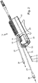
- Figur 1
- eine Katheterpumpe mit einer Antriebseinheit und einem Katheter;
- Figur 2
- eine Antriebseinheit einer Katheterpumpe in Betriebslage;
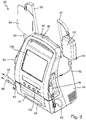
- Figur 3
- eine Perspektivansicht einer Konsole eines erfindungsgemäßen Spülsystems mit einem daran befestigten Trägerelement und einem Schließelement in Geschlossenstellung;
- Figur 4
- Ansicht gemäß
Figur 3 mit dem Schließelement in Offenstellung, wobei das Trägerelement von der Konsole gelöst ist; - Figur 5
- eine perspektivische Ansicht des in den
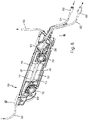
Figuren 3 und4 gezeigten Trägerelements; - Figur 6
- eine weitere perspektivische Ansicht des in den
Figuren 3 und4 gezeigten Trägerelements; - Figur 7
- schematische perspektivische Ansicht einer Pumpe der in den
Figuren 3 und4 gezeigten Konsole; und - Figur 8
- schematische perspektivische Ansicht des Schließelements der in den
Figuren 3 und4 gezeigten Konsole. - In den
Figuren 1 und2 ist eine Katheterpumpe 10 mit einer Antriebseinheit 12 und mit einem mit der Antriebseinheit 12 koppelbaren Katheter 18 gezeigt. Der Katheter 18 weist an seinem distalen Ende einen Pumpenkopf 15 zum Einführen in das arterielle Gefäßsystem wie zum Beispiel die Aorta auf. Der Katheter 18 ist dafür bestimmt, in den Körper eines Säugetiers, wie zum Beispiel eines Menschen, über die Oberschenkelarterie eingeführt zu werden und um zum Beispiel in der Aorta positioniert zu werden für eine Unterstützung des Kreislaufs des Herzens. Der Katheter 18 ist relativ lang, so dass er sich von der perkutanen Einführungsstelle in zum Beispiel der Oberschenkelarterie in die Leistengegend und bis hinauf zu dem Aortabogen erstrecken kann. - Im Katheter 18 ist eine Rotorwelle 32 vorgesehen, mittels der ein im Pumpenkopf 15 vorgesehenes Förderelement, beispielsweise einen Rotor mit ausklappbaren Propellern, in Rotation versetzbar ist. Die Antriebseinheit 12 weist eine Aufnahme 14 auf. Das proximale Ende 16 des Katheters 18 ist dabei in der Aufnahme 14 angeordnet und wird dort mittels eines Halteelements 20 sicher gehalten. An seinem proximalen Ende 16 sieht der Katheter 18 einen Kopplungsabschnitt 30 vor, der in die Antriebseinheit 12 einlegbar ist, mittels welcher letztlich die Rotorwelle 32, und damit das Förderelement, in Rotation versetzbar ist.
- Ferner sind am distalen Ende 16 zwei Schläuche 22, 24 vorgesehen. Über den Schlauch 22 kann über einen Einlauf 26 Spülfluid in den Katheter 18 eingeleitet werden. Dieses Spülfluid wird durch den Katheter 18 zum Pumpenkopf 15 geleitet. Im Pumpenkopf 15 wird ein Teil dieses Spülfluids wieder durch den Katheter 18 zurückgeführt und über einen Auslauf 28 und den Schlauch 24 ausgelassen. Das rückgeführte Spülfluid wird dabei zwischen der sich im Betrieb drehenden Rotorwelle 32 und einem Innenkatheter 33 rückgeführt. Der Innenkatheter 33 wird dabei von einem Außenkatheter 35 umgeben, wobei Spülfluid über das Lumen zwischen dem Innenkatheter 33 und dem Außenkatheter 35 hin zum Pumpenkopf 15 gefördert wird.
- Die Schläuche 22, 24 weisen jeweils ein Anschlussstück 36, 38 auf. Diese Anschlussstücke 36, 38 sind mit einem Spülsystem verbindbar, welches im Folgenden näher beschrieben wird. Das Spülsystem ist in den
Figuren 3 und4 gezeigt und insgesamt mit dem Bezugszeichen 40 bezeichnet. Zunächst umfasst das Spülsystem 40 eine Konsole 42. Diese umfasst an ihrer Rückseite zwei Haken 44, 46 mittels welcher die Konsole beispielsweise an einem Krankhausbett befestigbar ist. Ferner umfasst die Konsole 42 einen Halteabschnitt 48, so dass die Konsole 42 von einer Bedienperson bequem getragen werden kann. Ferner umfasst die Konsole eine inFigur 4 zu erkennende Aufnahme 50, die von einem verschwenkbaren Schließelement 51 verschließbar ist. - Weiterhin umfasst die Konsole 42 eine als lineare Peristaltikpumpe ausgebildete Pumpe 52. Diese Pumpe 52 wird im Folgenden anhand der
Figuren 4 und7 näher beschrieben: Zunächst umfasst die Pumpe 52 eine Nockenwelle 56, mit einer Anzahl nicht gezeigter Nocken. Die Nocken sind jeweils mit einem Finger 54 bewegungsgekoppelt. Diese Finger 54 bewegen sich in radialer Richtung, also senkrecht zur Drehachse der Nockenwelle 56. Die Finger 54 bewegen sich hierbei sequenziell, das heißt insgesamt bewegen sich die Finger 54 zusammen wellenförmig. InFigur 4 sind die Finger zu erkennen, die in die Aufnahme 50 ragen und von einer Bedeckung 58 bedeckt werden. In der Aufnahme 50 ist ein Trägerelement 60 mit einer Zuführleitung 62 und einer Abführleitung 64 anordenbar. - Das Trägerelement 60 sowie die Leitungen 62, 64 werden im Folgenden anhand der
Figuren 3 bis 6 näher beschrieben. Zunächst umfasst die Zuführleitung 62 ein Anschlussstück 66, während die Abführleitung 64 ein Anschlussstück 68 umfasst. Das Anschlussstück 66 ist hierbei mit dem Anschlussstück 36 des Schlauchs 22 der Katheterpumpe 10 (vgl.Figur 2 ) verbindbar. Die Anschlussstücke 66 und 36 können einen Luer-Anschluss ausbilden. Ebenso ist das Anschlussstück 68 der Abführleitung 64 mit dem Anschlussstück 38 des Schlauchs 24 der Katheterpumpe 10 verbindbar. Die Anschlussstücke 38 und 68 können ebenfalls einen Luer-Anschluss ausbilden. - Wie den
Figuren 5 und6 deutlich zu entnehmen ist, erstreckt sich das Trägerelement 60 in einer Haupterstreckungsebene und ist kassettenartig aufgebaut. Das Trägerelement 60 besteht aus PET und wird durch Kunststoff Tiefziehen oder Spritzguss hergestellt. Die Zuführleitung 62 und die Abführleitung 64 sind am Trägerelement 60 befestigt bzw. verlaufen durch das Trägerelement 60 hindurch. Das Trägerelement 60 weist hierzu Kanäle auf, in denen die Leitungen 62, 64 geführt sind. Im mittleren Bereich weist das Trägerelement 60 einen rechteckförmigen Durchbruch 70 auf. Die Leitungen 62, 64 erstrecken sich entlang dieses Durchbruchs 70 und überbrücken diesen. - Im Bereich des Durchbruchs 70 umfasst die Zuführleitung 62 einen Pumpabschnitt 72. Gleichzeitig umfasst die Abführleitung 64 einen Pumpabschnitt 74. Der Pumpabschnitt 72 weist einen Durchmesser d1 auf, während der Pumpabschnitt 74 einen Durchmesser d2 aufweist. Der Durchmesser d1 ist hierbei größer als der Durchmesser d2. Die Funktion dieser Durchmesserdifferenz wird im Folgenden noch näher beschrieben werden.
- Am Trägerelement 60 sind ferner zwei Membranen 76, 78, die insbesondere aus Silikon bestehen können, vorgesehen. Mittels dieser Membranen 76, 78 ist eine Druckmessung in der Zuführleitung 62 bzw. der Abführleitung 64 durchführbar, wie im Folgenden noch näher beschrieben werden wird. Ferner weist das Trägerelement 60 einen weiteren Durchbruch 80 auf. Dieser Durchbruch 80 wird nur von der Zuführleitung 62 überbrückt. Wie in den
Figuren 3 und4 ersichtlich ist, weist die Zuführleitung 62 ein weiteres Anschlussstück 82 auf. Mittels dieses Anschlussstücks 82 ist der Zuführschlauch 62 mit einem Beutel 84 verbindbar. Der Beutel 84 enthält Spülfluid. Der Beutel 84 ist an einem Befestigungshaken 85 der Konsole 42 befestigt. Ferner umfasst die Zuführleitung 62 eine Behälter 86 mit vergrößertem Durchmesser. Dieser Behälter 86 liegt zwischen dem Anschlussstück 82 und dem Trägerelement 60. Der Behälter 86 ist an einer Aufnahme 88 an der Konsole befestigbar und liegt an einem konsolenseitigen Fenster 90 an. Mittels dieser Anordnung kann eine Füllstandsmessung der Zuführleitung 62 beispielsweise mittels eines kapazitiven Sensors bereitgestellt werden. Die Abführleitung 64 weist ebenfalls ein Anschlussstück 92 auf. Das Anschlussstück 92 ist hierbei mit einem Auffangbeutel 94 für verbrauchtes Spülfluid verbindbar. Der Auffangbeutel 94 ist ebenfalls an einem Befestigungshaken 95 der Konsole 42 befestigt. Die Befestigungshaken 85, 95 samt den Beuteln 84, 94 sind an gegenüberliegenden Schmalseiten der Konsole 42 vorgesehen. - Zum Befestigen des Trägerelements 60 in der Aufnahme 50 weist die Konsole eine Anzahl Fixierungsbolzen 96 auf. Sobald das Trägerelement 60 in der Aufnahme 50 angeordnet ist, kann die Aufnahme 50 geschlossen werden, wie in
Figur 3 gezeigt ist. Hierzu wird das Schließelement 51 aus der inFigur 4 gezeigten Offenstellung in seine inFigur 3 gezeigte Geschlossenstellung überführt. Zum Schließen des Schließelements 51 weist dieses eine Schließklappe 98 auf. Die Schließklappe 98 ist inFigur 8 besonders deutlich zu erkennen. Diese ist verschwenkbar. Um das Schließelement 51 zu schließen, wird die Schließklappe 98 verschwenkt, sodass Zähne 100 der Schließklappe 98 einen konsolenseitigen Befestigungssteg 102 hintergreifen, so dass das Schließelement 51 in der Geschlossenstellung sicher geschlossen ist. - Wie aus
Figur 3 ersichtlich ist, wird die Zuführleitung 62 an einer Seite der Konsole 42 in dieser hinein geführt und an einer gegenüberliegenden Seite hinausgeführt. Demgegenüber wird die Abführleitung 64 an derselben Seite der Konsole 42 in diese hineingeführt bzw. aus dieser hinausgeführt, nämlich an der Seite, wo die Abführleitung 64 aus der Konsole 42 in Richtung der Katheterpumpe 10 hinausgeführt wird. Dementsprechend ist die Abführleitung 64 in einem Bogen (inFig. 6 erkennbar) durch das Trägerelement 60 geführt, sodass die Abführleitung 64 einen bogenförmigen Abschnitt 69 aufweist. - Um die Zuführleitung 62 und die Abführleitung 64 gegen die Finger 54 der Pumpe 52 in der Geschlossenstellung des Schließelements 51 zu beaufschlagen, weist das Schließelement 51 jeweils ein Drückelement 104, 106 für die Zuführleitung 62 und die Abführleitung 64 auf. Diese Drückelemente 104, 106 sind in
Figur 7 deutlich zu erkennen. Diese erstrecken sich dabei jeweils entlang der Pumpabschnitte 72, 74 und werden an den seitlichen Enden von jeweils mindestens einem Federelement 108, 110 gegen die Finger 54 beaufschlagt. Wie inFigur 4 ersichtlich ist, ist eine Bedeckung 112 über den Drückelementen 104, 106 angeordnet. - Ferner weist das Schließelement 51 jeweils ein ebenfalls in
Figur 7 zu erkennendes Beaufschlagungselement 114, 116 auf, wobei auch hier jeweils eine Druckfeder 118, 120 vorgesehen ist. Die Beaufschlagungselemente 114, 116 wirken hierbei mit den Membranen 66, 68 sowie konsolenseitig vorgesehenen Sensorelementen 122, 124 (vgl.Figur 4 ) zusammen, so dass eine Druckmessung in der Zuführleitung 62 und in der Abführleitung 64 möglich ist. In die Aussparung 80 im Trägerelement 60 greifen in der Geschlossenstellung ein konsolenseitiges Sensorelement 126 sowie ein schließelementseitiger Steg 128 ein, die auf die Zuführleitung 62 so wirken, dass eine Luftblasenerkennung durchführbar ist. In der Zuführleitung 62 sollen nämlich möglichst keine Luftbläschen oder sonstige Gasbläschen durchgelassen werden. Eine Luftblasenerkennung kann hierbei beispielsweise mittels optischer Methoden oder mittels kapazitiver Messung durchgeführt werden. - Die Funktionsweise des Spülsystems 40 ist sodann wie folgt: Zunächst wird das Spülsystem 40 mit der Katheterpumpe 10 verbunden, um ein Katheterpumpensystem auszubilden. Dabei wird der Anschluss 66 der Zuführleitung 62 mit dem Anschluss 36 der Katheterpumpe verbunden. Gleichermaßen wird der Anschluss 68 der Abführleitung 64 mit dem Anschluss 38 der Katheterpumpe 10 verbunden. Sodann kann die Pumpe 52 gestartet werden. Daraufhin wird Spülfluid, ausgehend vom Beutel 84 über die Zuführleitung 62 den Schlauch 22 dem Katheter 18 der Katheterpumpe 10 zuführt. Die Spülfluid kann hierbei aus einer 20%igen sterilen Glukoselösung bestehen. Heparin kann dem Spülfluid hinzugefügt sein. Die Menge des Spülfluids kann auf 600-2500ml/24h im Betrieb, und beim Befüllen mit deutlich größerem Fluss, ca. 12000ml/24h eingestellt sein.
- Der Katheter 10 wird sodann in distaler Richtung vom Spülfluid durchströmt. Ein Teil des Spülfluids wird daraufhin durch den Katheter 18 hindurch in proximaler Richtung zurückgeführt und wirkt dabei als Schmiermittel für die Rotorwelle 32 des Katheters 18. Ferner wird das Eindringen von Blut in den Katheter 18 durch das Spülfluid wirksam verhindert. Über den Schlauch 24 und die Rückführleitung 64 wird das verbrauchte Spülfluid sodann dem Auffangbeutel 94 zugeführt. Dadurch, dass der Durchmesser d2 des Pumpenabschnitts 74 der Rückführleitung 64 kleiner ist als der Durchmesser d1 des Pumpenabschnitts 72 der Zuführleitung 62, wirkt der Pumpenabschnitt 64 mit der Pumpe 52 als Drosselstelle zusammen. Somit wird ca. ein Drittel des in den Katheter 18 gepumpten Spülfluids wieder aus dem Katheter herausgepumpt, während zwei Drittel des Spülfluids in den Kreislauf des Patienten eindringend, wobei zugleich verhindert wird, dass Blut in den Katheter 18 eindringt. Dementsprechend ist die Querschnittsfläche des Durchmessers d2 des Pumpenabschnitts 74 der Rückführleitung 64 auch ungefähr nur ein Drittel des der Querschnittsfläche mit dem Durchmesser d1 des Pumpenabschnitts 72 der Zuführleitung 62.
- Jeder Finger 54 der Pumpe 52 wirkt dabei auf beide Pumpenabschnitte 72 und 74 gleichermaßen. Die lineare Peristaltikpumpe 52 ist eine Verdrängerpumpe, bei der das zu fördernde Spülfluid durch äußere mechanische Verformung der Leitungen 62, 64 bzw. deren Pumpabschnitte 72, 74 hindurchgedrückt wird, wobei der zusammengedrückte Abschnitt der Pumpabschnitte 72, 74 "wandert", aufgrund der sequenziellen axialen Bewegung der Finger 54. Mittels der Sensorelemente 122, 124 ist eine Druckmessung in den Leitungen 62, 64 möglich, während mittels des Sensorelements 126 eine Luftblasenerkennung in der Zuführleitung 62 möglich ist.
- Die hauptsächlichen Funktionen der Konsole 42 sind, die Drehzahl der Katheterpumpe 10 bzw. die Durchflussmenge des Spülfluids zu überwachen und zu steuern. Die Konsole 42 weist an einer Breitseite zwei Monitore auf. Der erste Monitor 130 dient als Hauptmonitor und ist als Touchscreen ausgebildet. Alle Steuerungs- und Überwachungsparameter für das System werden am Monitor 130 angezeigt. Ein Betriebssystem, wie beispielsweise Windows, dient hierbei als Eingabesystem auf dem Bildschirm. Ein davon getrenntes Betriebssystem, welches speziell für die Medizinelektronik ausgebildet ist, dient zur Steuerung der Katheterpumpe 10 und/oder des Spülsystems 40. Die Steuerung für die Medizinelektronik dient hierbei insbesondere zur Drehzahlkontrolle der Katheterpumpe 10 bzw. der Pumpe 52 des Spülsystems 40. Sollte der Monitor 130 aus irgendwelchen Gründen ausfallen, weist die Konsole 42 einen zweiten Notmonitor 132 auf. Dieser hat nur wenige Funktionen, wie beispielsweise eine Anzeige der Drehzahl der Katheterpumpe 10. Mittels dieses sogenannten SUI (Sicherheits-User-Interface) kann der Betrieb der Katheterpumpe 10 und/oder des Spülsystems 40 lediglich beendet werden, nicht jedoch gestartet werden.
Claims (11)
- Spülsystem (40) für einen Katheter (18), umfassend eine Zuführleitung (62) mit einem Pumpabschnitt, eine Abführleitung (64) mit einem Pumpabschnitt und eine Pumpe (52),dadurch gekennzeichnet,dass der Durchmesser d2 des Pumpabschnitts (74) der Abführleitung (64) kleiner ist als der Durchmesser d1 des Pumpabschnitts (72) der Zuführleitung (62),dass die Pumpe (52) mit dem Pumpabschnitt (72) der Zuführleitung (62) zum Zuführen von Spülfluid zum Katheter (18) zusammenwirkt,dass die Pumpe (52) mit dem Pumpabschnitt (74) der Abführleitung (64) zum Abführen von Spülfluid aus dem Katheter (18) zusammenwirkt,wobei ein Trägerelement (60) vorgesehen ist, an dem die Zuführleitung (62) und die Abführleitung (64) befestigt sind,wobei sich das Trägerelement (60) entlang einer Haupterstreckungsebene erstreckt, wobei die Zuführleitung (62) und Abführleitung (64) in dieser Haupterstreckungsebene durch das Trägerelement (60) verlaufen,wobei das Trägerelement (60) einen Durchbruch (70) aufweist, und wobei sich die Pumpabschnitte (72, 74) der Zuführleitung (62) und der Abführleitung (64) entlang des Durchbruchs (70) erstrecken, wobei die Pumpe (52) als lineare Peristaltikpumpe ausgebildet ist, wobei die Pumpe (52) eine Nockenwelle (56) mit einer Anzahl Nocken aufweist, wobei jeder Nocken mit jeweils einem Finger (54) bewegungsgekoppelt ist, wobei jeder Finger (54) zur Fluidförderung mit der Zuführleitung (62) und der Abführleitung (64) zusammenwirkt, und wobei die Finger (54) die Zuführleitung (62) und die Abführleitung (64) sequentiell zusammendrücken, um eine Fluidströmung zu erzeugen.
- Spülsystem (40) nach einem der vorhergehenden Ansprüche, wobei die Pumpabschnitte (72, 74) parallel zueinander verlaufen und in Betrieb von Spülfluid in entgegengesetzten Strömungsrichtungen durchströmt werden.
- Spülsystem (40) nach einem der vorhergehenden Ansprüche, wobei die Zuführleitung (62) bzw. die Abführleitung (64) einen bogenförmigen Abschnitt (69) aufweist, wobei der Abschnitt durch das Trägerelement (60) verläuft, sodass die Zuführleitung (62) bzw. Abführleitung (64) derselben Seite in das Trägerelement (60) hinein bzw. aus dem Trägerelement (60) hinaus geführt ist.
- Spülsystem (40) nach einem der vorhergehenden Ansprüche, wobei eine die Pumpe (52) aufweisende Konsole (42) vorgesehen ist, wobei die Pumpabschnitte (72, 74) in eine Aufnahme (50) in der Konsole (42) derart einführbar sind, dass die Pumpe (52) mit den Pumpabschnitten (72, 74) zur Fluidförderung zusammenwirken kann.
- Spülsystem (40) nach Anspruch 4, wobei das Trägerelement (60) samt Zuführleitung (62) und Abführleitung (64) an der Konsole (42) lösbar anlegbar ist.
- Spülsystem (40) nach Anspruch 4 oder 5, wobei die Konsole (42) ein Schließelement (51) zum Verschließen der Aufnahme (50) aufweist, wobei die Pumpabschnitte (72, 74) erst dann mit der Pumpe (52) zur Fluidförderung zusammenwirken, wenn das Schließelement (51) seine Geschlossenstellung einnimmt.
- Spülsystem (40) nach Anspruch 6, wobei das Schließelement (51) ein Drückelement (104, 106) aufweist, das die Zuführleitung (62) und/oder die Abführleitung (64) unter Vorspannung gegen die Finger (54) drücken.
- Spülsystem (40) nach Anspruch 7, wobei jeweils ein Drückelement (104, 106) für die Zuführleitung (62) und die Abführleitung (64) vorgesehen ist.
- Trägerelement (60) zum Einführen in die Aufnahme (50) der die Pumpe (52) aufweisenden Konsole (42) eines Spülsystems (40) nach einem der Ansprüche 4 bis 8, wobei am Trägerelement (60) die Zuführleitung (62) und die Abführleitung (64) befestigt sind,wobei sich das Trägerelement (60) entlang einer Haupterstreckungsebene erstreckt,wobei die Zuführleitung (62) und Abführleitung (64) in dieser Haupterstreckungsebene durch das Trägerelement (60) verlaufen,wobei das Trägerelement (60) einen Durchbruch (70) aufweist, undwobei sich die Pumpabschnitte (72, 74) der Zuführleitung (62) und der Abführleitung (64) entlang des Durchbruchs (70) erstrecken und den Durchbruch (70) derart überbrücken, dass bei in die Konsole (42) eingesetztem Trägerelement (60) die Finger (54) der Pumpe (52) mit den den Durchbruch (70) überbrückenden Pumpabschnitten (72, 74) zusammenwirken.
- Konsole (42) für ein Spülsystem (40) nach einem der Ansprüche 4 bis 8, wobei die Konsole (42) die Pumpe (52) und die Aufnahme (50) für das Trägerelement (60) nach Anspruch 9 aufweist,wobei die Pumpe (52) als lineare Peristaltikpumpe ausgebildet ist, die eine Nockenwelle (56) mit einer Anzahl Nocken aufweist, wobei jeder Nocken mit jeweils einem Finger (54) bewegungsgekoppelt ist, undwobei die Pumpe (52) und deren Finger (54) derart ausgebildet sind, dass die Finger (54) bei in der Aufnahme eingeführtem Trägerelement (60) mit den den Durchbruch (70) des Trägerelements (60) überbrückenden Pumpabschnitten (72, 74) zusammenwirken und die Zuführleitung (62) und die Abführleitung (64) sequentiell zusammendrücken, um eine Fluidströmung zu erzeugen.
- Katheterpumpensystem umfassend eine Katheterpumpe (10) mit einem Katheter (18) und ein Spülsystem (40) nach einem der Ansprüche 1 bis 8, wobei die Zuführleitung (62) und die Abführleitung (64) mit dem Katheter (18) fluidisch verbunden sind.
Applications Claiming Priority (2)
| Application Number | Priority Date | Filing Date | Title |
|---|---|---|---|
| DE102017102829.3A DE102017102829A1 (de) | 2017-02-13 | 2017-02-13 | Spülsystem |
| PCT/EP2018/051053 WO2018145865A1 (de) | 2017-02-13 | 2018-01-17 | Spülsystem |
Publications (2)
| Publication Number | Publication Date |
|---|---|
| EP3579903A1 EP3579903A1 (de) | 2019-12-18 |
| EP3579903B1 true EP3579903B1 (de) | 2022-12-21 |
Family
ID=61017922
Family Applications (1)
| Application Number | Title | Priority Date | Filing Date |
|---|---|---|---|
| EP18701009.5A Active EP3579903B1 (de) | 2017-02-13 | 2018-01-17 | Spülsystem |
Country Status (8)
| Country | Link |
|---|---|
| US (1) | US11679232B2 (de) |
| EP (1) | EP3579903B1 (de) |
| JP (1) | JP6882495B2 (de) |
| CN (1) | CN110290826B (de) |
| DE (1) | DE102017102829A1 (de) |
| ES (1) | ES2940085T3 (de) |
| RU (1) | RU2721583C1 (de) |
| WO (1) | WO2018145865A1 (de) |
Families Citing this family (12)
| Publication number | Priority date | Publication date | Assignee | Title |
|---|---|---|---|---|
| US12491356B2 (en) | 2018-03-20 | 2025-12-09 | Second Heart Assist, Inc. | Circulatory assist pump |
| JP2021518249A (ja) | 2018-03-20 | 2021-08-02 | セカンド・ハート・アシスト・インコーポレイテッド | 循環補助ポンプ |
| US11690997B2 (en) | 2018-04-06 | 2023-07-04 | Puzzle Medical Devices Inc. | Mammalian body conduit intralumenal device and lumen wall anchor assembly, components thereof and methods of implantation and explanation thereof |
| CN112566689A (zh) * | 2018-06-13 | 2021-03-26 | 耶鲁大学 | 心内装置 |
| US11179557B2 (en) | 2019-03-26 | 2021-11-23 | Puzzle Medical Devices Inc. | Modular mammalian body implantable fluid flow influencing device and related methods |
| US12383723B2 (en) | 2019-10-05 | 2025-08-12 | Puzzle Medical Devices Inc. | Mammalian body implantable fluid flow influencing device |
| CN115701364B (zh) * | 2021-08-02 | 2024-08-23 | 嘉善飞阔医疗科技有限公司 | 一种超声波手术刀的清洗系统及清洗方法 |
| US12544560B2 (en) | 2022-01-14 | 2026-02-10 | Second Heart Assist, Inc. | Wireless chronic implant |
| CN115055455B (zh) * | 2022-06-09 | 2023-05-16 | 江阴市人民医院 | 一种外科护理用的辅助清洗设备 |
| IL320366A (en) | 2022-11-01 | 2025-06-01 | Puzzle Medical Devices Inc | Missile medical devices and methods related thereto |
| CN118108170A (zh) * | 2022-11-30 | 2024-05-31 | 深圳赛桥生物创新技术有限公司 | 转液设备 |
| CN117643679A (zh) * | 2023-11-30 | 2024-03-05 | 心擎医疗(苏州)股份有限公司 | 用于经导管心室辅助装置的冲洗信息检测方法及装置 |
Family Cites Families (39)
| Publication number | Priority date | Publication date | Assignee | Title |
|---|---|---|---|---|
| US3306228A (en) * | 1965-08-20 | 1967-02-28 | Trw Inc | Combination gear and vane pump |
| IL44372A (en) * | 1974-03-08 | 1976-10-31 | Drori Mordeki | Fluid-driven feeding device for liquid materials |
| DE3132790A1 (de) | 1981-08-19 | 1983-03-17 | Dr. Eduard Fresenius, Chemisch-pharmazeutische Industrie KG, 6380 Bad Homburg | Kuenstliche niere |
| DE8418491U1 (de) * | 1984-06-19 | 1984-09-20 | Richard Wolf Gmbh, 7134 Knittlingen | Schlauchpumpe fuer spuelfluessigkeiten |
| EP0172336A1 (de) * | 1984-08-24 | 1986-02-26 | GebràDer Sulzer Aktiengesellschaft | Vorrichtung zum gleichmässigen Verteilen eines Zwei-Phasengemisches |
| US4976590A (en) * | 1988-06-08 | 1990-12-11 | Baldwin Brian E | Fluid conduit-responsively adjustable pump arrangement and pump/conduit arrangement and method, and fluid conduits therefor |
| US5098261A (en) * | 1990-05-04 | 1992-03-24 | Brandel Corporation | Peristaltic pump and method for adjustable flow regulation |
| US5340290A (en) * | 1992-12-21 | 1994-08-23 | Scilog, Inc. | Double feed peristaltic pump |
| US5403277A (en) * | 1993-01-12 | 1995-04-04 | Minnesota Mining And Manufacturing Company | Irrigation system with tubing cassette |
| US5460490A (en) * | 1994-05-19 | 1995-10-24 | Linvatec Corporation | Multi-purpose irrigation/aspiration pump system |
| EP0711570A1 (de) * | 1994-11-14 | 1996-05-15 | Siemens-Elema AB | Verfahren und Vorrichtung zur Innenreinigung eines implantierten Infusionssystems |
| JP2891669B2 (ja) | 1996-05-21 | 1999-05-17 | メディス有限会社 | 溶液混合移送装置及び灌流装置 |
| IL120654A (en) * | 1997-04-11 | 2001-08-08 | Nestle Sa | Administration of two liquids to a patient |
| JP4225611B2 (ja) * | 1998-08-27 | 2009-02-18 | オリンパス株式会社 | 内視鏡用管路洗滌装置 |
| JP2000229063A (ja) * | 1999-02-10 | 2000-08-22 | Fuji Photo Optical Co Ltd | 内視鏡管路の洗浄装置 |
| US6585692B1 (en) * | 1999-02-19 | 2003-07-01 | Alsius Corporation | Method and system for patient temperature management and central venous access |
| JP2001218841A (ja) * | 2000-02-08 | 2001-08-14 | Terumo Corp | 輸液ポンプ用カセットおよびそれを用いた輸液ポンプ |
| US6659976B2 (en) * | 2001-04-16 | 2003-12-09 | Zevek, Inc. | Feeding set adaptor |
| DE20209663U1 (de) | 2002-06-21 | 2003-10-23 | B. Braun Melsungen Ag, 34212 Melsungen | Infusionspumpe |
| US7238010B2 (en) * | 2003-04-14 | 2007-07-03 | Stryker Corporation | Surgical irrigation pump and tool system |
| US7591639B2 (en) * | 2004-04-27 | 2009-09-22 | Hewlett-Packard Development Company, L.P. | Peristaltic pump |
| DE102006022122A1 (de) * | 2006-05-11 | 2007-11-15 | Fresenius Medical Care Deutschland Gmbh | Verfahren zur Füllung und Spülung eines Blutschlauchsatzes |
| US20090053085A1 (en) * | 2007-08-24 | 2009-02-26 | Thompson Loren M | Peristalitic pump assembly and method for attaching a cassette thereto |
| EP3037117B1 (de) * | 2007-10-12 | 2017-12-20 | DEKA Products Limited Partnership | Blutschlauchverbinder |
| US8114276B2 (en) | 2007-10-24 | 2012-02-14 | Baxter International Inc. | Personal hemodialysis system |
| JP5058759B2 (ja) * | 2007-11-28 | 2012-10-24 | 富士フイルム株式会社 | 内視鏡搬送ケース |
| US9827367B2 (en) * | 2008-04-29 | 2017-11-28 | Medtronic Xomed, Inc. | Surgical instrument, system, and method for frontal sinus irrigation |
| DE202009018145U1 (de) | 2008-06-23 | 2011-05-05 | Cardiobridge Gmbh | Katheterpumpe für die Unterstützung des Kreislaufs |
| US8388582B2 (en) * | 2009-08-12 | 2013-03-05 | Medrad, Inc. | Systems and methods for operating interventional catheters using a common operating console and adaptive interface components |
| JP2011206211A (ja) * | 2010-03-29 | 2011-10-20 | Terumo Corp | 輸液ポンプ |
| DE102010031793B4 (de) | 2010-07-30 | 2012-12-06 | Günter Heeke | Bilanzierungspumpenanordnung und Leitungsanordnung dafür |
| US8377001B2 (en) * | 2010-10-01 | 2013-02-19 | Abbott Laboratories | Feeding set for a peristaltic pump system |
| KR101854585B1 (ko) * | 2012-11-14 | 2018-06-20 | 코비디엔 엘피 | 연동 펌프 카세트 |
| WO2014092851A1 (en) * | 2012-12-11 | 2014-06-19 | Alcon Research, Ltd. | Phacoemulsification hand piece with integrated aspiration and irrigation pump |
| CN103961757B (zh) * | 2013-01-29 | 2016-08-03 | 中国人民解放军总医院 | 智能膀胱冲洗控制系统 |
| JP6530367B2 (ja) | 2013-03-13 | 2019-06-12 | ティーシーワン エルエルシー | 流体導出入システム |
| CN105979982B (zh) * | 2014-12-12 | 2017-11-14 | 泽维克斯公司 | 输液泵盒以及被构造成有助于盒移除的盒接口 |
| EP3277235A4 (de) * | 2015-04-03 | 2019-05-15 | Cirrus Technologies Ltd. | Chirurgisches flüssigkeitsmanagementsystem |
| CN105840471A (zh) * | 2016-05-04 | 2016-08-10 | 嘉兴栋马童车有限公司 | 蠕动泵 |
-
2017
- 2017-02-13 DE DE102017102829.3A patent/DE102017102829A1/de not_active Ceased
-
2018
- 2018-01-17 US US16/484,814 patent/US11679232B2/en active Active
- 2018-01-17 EP EP18701009.5A patent/EP3579903B1/de active Active
- 2018-01-17 JP JP2019541787A patent/JP6882495B2/ja active Active
- 2018-01-17 ES ES18701009T patent/ES2940085T3/es active Active
- 2018-01-17 RU RU2019128571A patent/RU2721583C1/ru active
- 2018-01-17 CN CN201880011636.2A patent/CN110290826B/zh active Active
- 2018-01-17 WO PCT/EP2018/051053 patent/WO2018145865A1/de not_active Ceased
Also Published As
| Publication number | Publication date |
|---|---|
| WO2018145865A1 (de) | 2018-08-16 |
| DE102017102829A1 (de) | 2018-08-16 |
| BR112019016609A2 (pt) | 2020-03-31 |
| RU2721583C1 (ru) | 2020-05-20 |
| JP6882495B2 (ja) | 2021-06-02 |
| ES2940085T3 (es) | 2023-05-03 |
| CN110290826B (zh) | 2021-09-10 |
| JP2020507384A (ja) | 2020-03-12 |
| CN110290826A (zh) | 2019-09-27 |
| EP3579903A1 (de) | 2019-12-18 |
| US11679232B2 (en) | 2023-06-20 |
| US20200023158A1 (en) | 2020-01-23 |
Similar Documents
| Publication | Publication Date | Title |
|---|---|---|
| WO2018145865A1 (de) | Spülsystem | |
| EP3241577B1 (de) | Verfahren zur füllung und spülung eines blutschlauchsatzes | |
| EP0720856B1 (de) | Anordnung zum On-Line Spülen und Befüllen eines extrakorporalen Blutkreislaufes von Dialysiermaschinen | |
| EP2303355B1 (de) | Vorrichtung zur peritonealdialyse | |
| DE102006012087B4 (de) | Verfahren zum zumindest teilweise Entleeren eines extrakorporalen Blutkreislaufs und Hämodialysegerät zur Anwendung des Verfahrens | |
| DE69525650T2 (de) | Peristaltische pumpe mit oklusivem eingang | |
| DE10040403A1 (de) | Intrakardiale Blutpumpe | |
| WO2015144628A2 (de) | Peristaltische pumpe, pumpvorrichtung und tragbare blutbehandlungsvorrichtung | |
| DE102005001779A1 (de) | Set für ein Disposable zum Betreiben einer Blutbehandlungsvorrichtung im Einnadel- oder Zweinadel-Betrieb | |
| DE4208054C2 (de) | Leitungs-System zum Spülen eines extrakorporalen Kreislaufs bei der Hämodialyse, Hämofiltration und Hämodiafiltration | |
| DE102011108777A1 (de) | Verfahren zum Entfernen von Blut aus einem extrakorporalen Blutkreislauf sowie Vorrichtungen | |
| DE60106231T2 (de) | Entnahmevorrichtung mit röhrchen unterschiedlichen querschnitts | |
| DE102011015075B4 (de) | Blutschlauchabschnitt zum extrakorporalen Führen von Blut, extrakorporaler Blutkreislauf, Behandlungsvorrichtung sowie Verfahren | |
| EP4136353A1 (de) | Peristaltikpumpe für eine vorrichtung zur extrakorporalen blutbehandlung | |
| WO2020178301A1 (de) | Extrakorporales blutleitungsset und blutbehandlungsmaschine | |
| EP1727574B1 (de) | Vorrichtung zum wechseln und/oder andocken von funktionsmodulen | |
| EP4161607B1 (de) | Verfahren zur diskonnektion | |
| EP2988661B1 (de) | Steuereinheit und verfahren zur bestimmung eines drucks in einem blutgefäss, insbesondere in einer arteriovenösen fistel | |
| DE19729022C2 (de) | Doppellumenkanüle | |
| DE102024123176A1 (de) | Medizinische Behandlungsvorrichtung | |
| WO2025131985A1 (de) | Vorrichtung zur extrakorporalen blutbehandlung und vorrichtung zum flussgerichteten sammeln von blutgerinnseln | |
| DE102023121091A1 (de) | Multiplex-Infusionssystem mit Steuervorrichtung, Katheter und Speichereinheit für ein solches Multiplex-Infusionssystem | |
| EP4108268A1 (de) | Bidirektionale kanüle | |
| WO2020208076A1 (de) | Rollenpumpe mit halteabschnitten zum festlegen eines pumpenschlauchsegments | |
| DE8629013U1 (de) | Schlauchsatz aus Kunststoff, insbesondere für die Peritonealdialyse |
Legal Events
| Date | Code | Title | Description |
|---|---|---|---|
| STAA | Information on the status of an ep patent application or granted ep patent |
Free format text: STATUS: UNKNOWN |
|
| STAA | Information on the status of an ep patent application or granted ep patent |
Free format text: STATUS: THE INTERNATIONAL PUBLICATION HAS BEEN MADE |
|
| PUAI | Public reference made under article 153(3) epc to a published international application that has entered the european phase |
Free format text: ORIGINAL CODE: 0009012 |
|
| STAA | Information on the status of an ep patent application or granted ep patent |
Free format text: STATUS: REQUEST FOR EXAMINATION WAS MADE |
|
| 17P | Request for examination filed |
Effective date: 20190829 |
|
| AK | Designated contracting states |
Kind code of ref document: A1 Designated state(s): AL AT BE BG CH CY CZ DE DK EE ES FI FR GB GR HR HU IE IS IT LI LT LU LV MC MK MT NL NO PL PT RO RS SE SI SK SM TR |
|
| AX | Request for extension of the european patent |
Extension state: BA ME |
|
| DAV | Request for validation of the european patent (deleted) | ||
| DAX | Request for extension of the european patent (deleted) | ||
| GRAP | Despatch of communication of intention to grant a patent |
Free format text: ORIGINAL CODE: EPIDOSNIGR1 |
|
| STAA | Information on the status of an ep patent application or granted ep patent |
Free format text: STATUS: GRANT OF PATENT IS INTENDED |
|
| RIC1 | Information provided on ipc code assigned before grant |
Ipc: A61M 60/226 20210101ALI20220622BHEP Ipc: A61M 60/808 20210101ALI20220622BHEP Ipc: A61M 60/554 20210101ALI20220622BHEP Ipc: A61M 60/408 20210101ALI20220622BHEP Ipc: A61M 60/13 20210101ALI20220622BHEP Ipc: F04B 43/12 20060101ALI20220622BHEP Ipc: A61M 5/142 20060101ALI20220622BHEP Ipc: A61M 25/00 20060101AFI20220622BHEP |
|
| INTG | Intention to grant announced |
Effective date: 20220707 |
|
| GRAS | Grant fee paid |
Free format text: ORIGINAL CODE: EPIDOSNIGR3 |
|
| GRAA | (expected) grant |
Free format text: ORIGINAL CODE: 0009210 |
|
| STAA | Information on the status of an ep patent application or granted ep patent |
Free format text: STATUS: THE PATENT HAS BEEN GRANTED |
|
| AK | Designated contracting states |
Kind code of ref document: B1 Designated state(s): AL AT BE BG CH CY CZ DE DK EE ES FI FR GB GR HR HU IE IS IT LI LT LU LV MC MK MT NL NO PL PT RO RS SE SI SK SM TR |
|
| REG | Reference to a national code |
Ref country code: GB Ref legal event code: FG4D Free format text: NOT ENGLISH |
|
| REG | Reference to a national code |
Ref country code: DE Ref legal event code: R096 Ref document number: 502018011263 Country of ref document: DE |
|
| REG | Reference to a national code |
Ref country code: CH Ref legal event code: EP |
|
| REG | Reference to a national code |
Ref country code: AT Ref legal event code: REF Ref document number: 1538682 Country of ref document: AT Kind code of ref document: T Effective date: 20230115 |
|
| REG | Reference to a national code |
Ref country code: IE Ref legal event code: FG4D Free format text: LANGUAGE OF EP DOCUMENT: GERMAN |
|
| REG | Reference to a national code |
Ref country code: LT Ref legal event code: MG9D |
|
| REG | Reference to a national code |
Ref country code: NL Ref legal event code: MP Effective date: 20221221 |
|
| PG25 | Lapsed in a contracting state [announced via postgrant information from national office to epo] |
Ref country code: SE Free format text: LAPSE BECAUSE OF FAILURE TO SUBMIT A TRANSLATION OF THE DESCRIPTION OR TO PAY THE FEE WITHIN THE PRESCRIBED TIME-LIMIT Effective date: 20221221 Ref country code: NO Free format text: LAPSE BECAUSE OF FAILURE TO SUBMIT A TRANSLATION OF THE DESCRIPTION OR TO PAY THE FEE WITHIN THE PRESCRIBED TIME-LIMIT Effective date: 20230321 Ref country code: LT Free format text: LAPSE BECAUSE OF FAILURE TO SUBMIT A TRANSLATION OF THE DESCRIPTION OR TO PAY THE FEE WITHIN THE PRESCRIBED TIME-LIMIT Effective date: 20221221 Ref country code: FI Free format text: LAPSE BECAUSE OF FAILURE TO SUBMIT A TRANSLATION OF THE DESCRIPTION OR TO PAY THE FEE WITHIN THE PRESCRIBED TIME-LIMIT Effective date: 20221221 |
|
| REG | Reference to a national code |
Ref country code: ES Ref legal event code: FG2A Ref document number: 2940085 Country of ref document: ES Kind code of ref document: T3 Effective date: 20230503 |
|
| PG25 | Lapsed in a contracting state [announced via postgrant information from national office to epo] |
Ref country code: RS Free format text: LAPSE BECAUSE OF FAILURE TO SUBMIT A TRANSLATION OF THE DESCRIPTION OR TO PAY THE FEE WITHIN THE PRESCRIBED TIME-LIMIT Effective date: 20221221 Ref country code: LV Free format text: LAPSE BECAUSE OF FAILURE TO SUBMIT A TRANSLATION OF THE DESCRIPTION OR TO PAY THE FEE WITHIN THE PRESCRIBED TIME-LIMIT Effective date: 20221221 Ref country code: HR Free format text: LAPSE BECAUSE OF FAILURE TO SUBMIT A TRANSLATION OF THE DESCRIPTION OR TO PAY THE FEE WITHIN THE PRESCRIBED TIME-LIMIT Effective date: 20221221 Ref country code: GR Free format text: LAPSE BECAUSE OF FAILURE TO SUBMIT A TRANSLATION OF THE DESCRIPTION OR TO PAY THE FEE WITHIN THE PRESCRIBED TIME-LIMIT Effective date: 20230322 |
|
| PG25 | Lapsed in a contracting state [announced via postgrant information from national office to epo] |
Ref country code: NL Free format text: LAPSE BECAUSE OF FAILURE TO SUBMIT A TRANSLATION OF THE DESCRIPTION OR TO PAY THE FEE WITHIN THE PRESCRIBED TIME-LIMIT Effective date: 20221221 |
|
| P01 | Opt-out of the competence of the unified patent court (upc) registered |
Effective date: 20230601 |
|
| PG25 | Lapsed in a contracting state [announced via postgrant information from national office to epo] |
Ref country code: SM Free format text: LAPSE BECAUSE OF FAILURE TO SUBMIT A TRANSLATION OF THE DESCRIPTION OR TO PAY THE FEE WITHIN THE PRESCRIBED TIME-LIMIT Effective date: 20221221 Ref country code: RO Free format text: LAPSE BECAUSE OF FAILURE TO SUBMIT A TRANSLATION OF THE DESCRIPTION OR TO PAY THE FEE WITHIN THE PRESCRIBED TIME-LIMIT Effective date: 20221221 Ref country code: PT Free format text: LAPSE BECAUSE OF FAILURE TO SUBMIT A TRANSLATION OF THE DESCRIPTION OR TO PAY THE FEE WITHIN THE PRESCRIBED TIME-LIMIT Effective date: 20230421 Ref country code: EE Free format text: LAPSE BECAUSE OF FAILURE TO SUBMIT A TRANSLATION OF THE DESCRIPTION OR TO PAY THE FEE WITHIN THE PRESCRIBED TIME-LIMIT Effective date: 20221221 Ref country code: CZ Free format text: LAPSE BECAUSE OF FAILURE TO SUBMIT A TRANSLATION OF THE DESCRIPTION OR TO PAY THE FEE WITHIN THE PRESCRIBED TIME-LIMIT Effective date: 20221221 |
|
| PG25 | Lapsed in a contracting state [announced via postgrant information from national office to epo] |
Ref country code: SK Free format text: LAPSE BECAUSE OF FAILURE TO SUBMIT A TRANSLATION OF THE DESCRIPTION OR TO PAY THE FEE WITHIN THE PRESCRIBED TIME-LIMIT Effective date: 20221221 Ref country code: PL Free format text: LAPSE BECAUSE OF FAILURE TO SUBMIT A TRANSLATION OF THE DESCRIPTION OR TO PAY THE FEE WITHIN THE PRESCRIBED TIME-LIMIT Effective date: 20221221 Ref country code: IS Free format text: LAPSE BECAUSE OF FAILURE TO SUBMIT A TRANSLATION OF THE DESCRIPTION OR TO PAY THE FEE WITHIN THE PRESCRIBED TIME-LIMIT Effective date: 20230421 Ref country code: AL Free format text: LAPSE BECAUSE OF FAILURE TO SUBMIT A TRANSLATION OF THE DESCRIPTION OR TO PAY THE FEE WITHIN THE PRESCRIBED TIME-LIMIT Effective date: 20221221 |
|
| REG | Reference to a national code |
Ref country code: DE Ref legal event code: R097 Ref document number: 502018011263 Country of ref document: DE |
|
| PG25 | Lapsed in a contracting state [announced via postgrant information from national office to epo] |
Ref country code: MC Free format text: LAPSE BECAUSE OF FAILURE TO SUBMIT A TRANSLATION OF THE DESCRIPTION OR TO PAY THE FEE WITHIN THE PRESCRIBED TIME-LIMIT Effective date: 20221221 Ref country code: LU Free format text: LAPSE BECAUSE OF NON-PAYMENT OF DUE FEES Effective date: 20230117 |
|
| REG | Reference to a national code |
Ref country code: BE Ref legal event code: MM Effective date: 20230131 |
|
| PLBE | No opposition filed within time limit |
Free format text: ORIGINAL CODE: 0009261 |
|
| STAA | Information on the status of an ep patent application or granted ep patent |
Free format text: STATUS: NO OPPOSITION FILED WITHIN TIME LIMIT |
|
| PG25 | Lapsed in a contracting state [announced via postgrant information from national office to epo] |
Ref country code: DK Free format text: LAPSE BECAUSE OF FAILURE TO SUBMIT A TRANSLATION OF THE DESCRIPTION OR TO PAY THE FEE WITHIN THE PRESCRIBED TIME-LIMIT Effective date: 20221221 |
|
| 26N | No opposition filed |
Effective date: 20230922 |
|
| PG25 | Lapsed in a contracting state [announced via postgrant information from national office to epo] |
Ref country code: BE Free format text: LAPSE BECAUSE OF NON-PAYMENT OF DUE FEES Effective date: 20230131 |
|
| PG25 | Lapsed in a contracting state [announced via postgrant information from national office to epo] |
Ref country code: SI Free format text: LAPSE BECAUSE OF FAILURE TO SUBMIT A TRANSLATION OF THE DESCRIPTION OR TO PAY THE FEE WITHIN THE PRESCRIBED TIME-LIMIT Effective date: 20221221 Ref country code: IE Free format text: LAPSE BECAUSE OF NON-PAYMENT OF DUE FEES Effective date: 20230117 |
|
| REG | Reference to a national code |
Ref country code: AT Ref legal event code: MM01 Ref document number: 1538682 Country of ref document: AT Kind code of ref document: T Effective date: 20230117 |
|
| PG25 | Lapsed in a contracting state [announced via postgrant information from national office to epo] |
Ref country code: AT Free format text: LAPSE BECAUSE OF NON-PAYMENT OF DUE FEES Effective date: 20230117 |
|
| PG25 | Lapsed in a contracting state [announced via postgrant information from national office to epo] |
Ref country code: AT Free format text: LAPSE BECAUSE OF NON-PAYMENT OF DUE FEES Effective date: 20230117 |
|
| PG25 | Lapsed in a contracting state [announced via postgrant information from national office to epo] |
Ref country code: BG Free format text: LAPSE BECAUSE OF FAILURE TO SUBMIT A TRANSLATION OF THE DESCRIPTION OR TO PAY THE FEE WITHIN THE PRESCRIBED TIME-LIMIT Effective date: 20221221 |
|
| PG25 | Lapsed in a contracting state [announced via postgrant information from national office to epo] |
Ref country code: BG Free format text: LAPSE BECAUSE OF FAILURE TO SUBMIT A TRANSLATION OF THE DESCRIPTION OR TO PAY THE FEE WITHIN THE PRESCRIBED TIME-LIMIT Effective date: 20221221 |
|
| PG25 | Lapsed in a contracting state [announced via postgrant information from national office to epo] |
Ref country code: CY Free format text: LAPSE BECAUSE OF FAILURE TO SUBMIT A TRANSLATION OF THE DESCRIPTION OR TO PAY THE FEE WITHIN THE PRESCRIBED TIME-LIMIT; INVALID AB INITIO Effective date: 20180117 |
|
| PG25 | Lapsed in a contracting state [announced via postgrant information from national office to epo] |
Ref country code: HU Free format text: LAPSE BECAUSE OF FAILURE TO SUBMIT A TRANSLATION OF THE DESCRIPTION OR TO PAY THE FEE WITHIN THE PRESCRIBED TIME-LIMIT; INVALID AB INITIO Effective date: 20180117 |
|
| REG | Reference to a national code |
Ref country code: CH Ref legal event code: U11 Free format text: ST27 STATUS EVENT CODE: U-0-0-U10-U11 (AS PROVIDED BY THE NATIONAL OFFICE) Effective date: 20260201 |
|
| PGFP | Annual fee paid to national office [announced via postgrant information from national office to epo] |
Ref country code: GB Payment date: 20260113 Year of fee payment: 9 |
|
| PGFP | Annual fee paid to national office [announced via postgrant information from national office to epo] |
Ref country code: ES Payment date: 20260217 Year of fee payment: 9 |
|
| PGFP | Annual fee paid to national office [announced via postgrant information from national office to epo] |
Ref country code: DE Payment date: 20260323 Year of fee payment: 9 |
|
| PGFP | Annual fee paid to national office [announced via postgrant information from national office to epo] |
Ref country code: IT Payment date: 20260130 Year of fee payment: 9 |
|
| PGFP | Annual fee paid to national office [announced via postgrant information from national office to epo] |
Ref country code: FR Payment date: 20260128 Year of fee payment: 9 |
|
| PGFP | Annual fee paid to national office [announced via postgrant information from national office to epo] |
Ref country code: TR Payment date: 20260115 Year of fee payment: 9 |
|
| PGFP | Annual fee paid to national office [announced via postgrant information from national office to epo] |
Ref country code: CH Payment date: 20260201 Year of fee payment: 9 |