EP3577451B1 - Steuerungssystem für eine sensoranordnung - Google Patents
Steuerungssystem für eine sensoranordnung Download PDFInfo
- Publication number
- EP3577451B1 EP3577451B1 EP18747814.4A EP18747814A EP3577451B1 EP 3577451 B1 EP3577451 B1 EP 3577451B1 EP 18747814 A EP18747814 A EP 18747814A EP 3577451 B1 EP3577451 B1 EP 3577451B1
- Authority
- EP
- European Patent Office
- Prior art keywords
- sensor assembly
- contaminants
- cleaning
- actuator
- exposed surface
- Prior art date
- Legal status (The legal status is an assumption and is not a legal conclusion. Google has not performed a legal analysis and makes no representation as to the accuracy of the status listed.)
- Active
Links
Images


Classifications
-
- B—PERFORMING OPERATIONS; TRANSPORTING
- B08—CLEANING
- B08B—CLEANING IN GENERAL; PREVENTION OF FOULING IN GENERAL
- B08B7/00—Cleaning by methods not provided for in a single other subclass or a single group in this subclass
- B08B7/02—Cleaning by methods not provided for in a single other subclass or a single group in this subclass by distortion, beating, or vibration of the surface to be cleaned
- B08B7/026—Using sound waves
- B08B7/028—Using ultrasounds
-
- B—PERFORMING OPERATIONS; TRANSPORTING
- B60—VEHICLES IN GENERAL
- B60S—SERVICING, CLEANING, REPAIRING, SUPPORTING, LIFTING, OR MANOEUVRING OF VEHICLES, NOT OTHERWISE PROVIDED FOR
- B60S1/00—Cleaning of vehicles
- B60S1/02—Cleaning windscreens, windows or optical devices
- B60S1/56—Cleaning windscreens, windows or optical devices specially adapted for cleaning other parts or devices than front windows or windscreens
-
- G—PHYSICS
- G01—MEASURING; TESTING
- G01K—MEASURING TEMPERATURE; MEASURING QUANTITY OF HEAT; THERMALLY-SENSITIVE ELEMENTS NOT OTHERWISE PROVIDED FOR
- G01K13/00—Thermometers specially adapted for specific purposes
-
- G—PHYSICS
- G01—MEASURING; TESTING
- G01N—INVESTIGATING OR ANALYSING MATERIALS BY DETERMINING THEIR CHEMICAL OR PHYSICAL PROPERTIES
- G01N29/00—Investigating or analysing materials by the use of ultrasonic, sonic or infrasonic waves; Visualisation of the interior of objects by transmitting ultrasonic or sonic waves through the object
- G01N29/02—Analysing fluids
- G01N29/022—Fluid sensors based on microsensors, e.g. quartz crystal-microbalance [QCM], surface acoustic wave [SAW] devices, tuning forks, cantilevers, flexural plate wave [FPW] devices
-
- G—PHYSICS
- G01—MEASURING; TESTING
- G01N—INVESTIGATING OR ANALYSING MATERIALS BY DETERMINING THEIR CHEMICAL OR PHYSICAL PROPERTIES
- G01N29/00—Investigating or analysing materials by the use of ultrasonic, sonic or infrasonic waves; Visualisation of the interior of objects by transmitting ultrasonic or sonic waves through the object
- G01N29/02—Analysing fluids
- G01N29/036—Analysing fluids by measuring frequency or resonance of acoustic waves
-
- G—PHYSICS
- G01—MEASURING; TESTING
- G01N—INVESTIGATING OR ANALYSING MATERIALS BY DETERMINING THEIR CHEMICAL OR PHYSICAL PROPERTIES
- G01N29/00—Investigating or analysing materials by the use of ultrasonic, sonic or infrasonic waves; Visualisation of the interior of objects by transmitting ultrasonic or sonic waves through the object
- G01N29/34—Generating the ultrasonic, sonic or infrasonic waves, e.g. electronic circuits specially adapted therefor
- G01N29/348—Generating the ultrasonic, sonic or infrasonic waves, e.g. electronic circuits specially adapted therefor with frequency characteristics, e.g. single frequency signals, chirp signals
-
- G—PHYSICS
- G01—MEASURING; TESTING
- G01R—MEASURING ELECTRIC VARIABLES; MEASURING MAGNETIC VARIABLES
- G01R31/00—Arrangements for testing electric properties; Arrangements for locating electric faults; Arrangements for electrical testing characterised by what is being tested not provided for elsewhere
- G01R31/34—Testing dynamo-electric machines
-
- G—PHYSICS
- G02—OPTICS
- G02B—OPTICAL ELEMENTS, SYSTEMS OR APPARATUS
- G02B27/00—Optical systems or apparatus not provided for by any of the groups G02B1/00 - G02B26/00, G02B30/00
- G02B27/0006—Optical systems or apparatus not provided for by any of the groups G02B1/00 - G02B26/00, G02B30/00 with means to keep optical surfaces clean, e.g. by preventing or removing dirt, stains, contamination, condensation
-
- H—ELECTRICITY
- H10—SEMICONDUCTOR DEVICES; ELECTRIC SOLID-STATE DEVICES NOT OTHERWISE PROVIDED FOR
- H10N—ELECTRIC SOLID-STATE DEVICES NOT OTHERWISE PROVIDED FOR
- H10N30/00—Piezoelectric or electrostrictive devices
- H10N30/20—Piezoelectric or electrostrictive devices with electrical input and mechanical output, e.g. functioning as actuators or vibrators
-
- H—ELECTRICITY
- H10—SEMICONDUCTOR DEVICES; ELECTRIC SOLID-STATE DEVICES NOT OTHERWISE PROVIDED FOR
- H10N—ELECTRIC SOLID-STATE DEVICES NOT OTHERWISE PROVIDED FOR
- H10N30/00—Piezoelectric or electrostrictive devices
- H10N30/80—Constructional details
- H10N30/802—Circuitry or processes for operating piezoelectric or electrostrictive devices not otherwise provided for, e.g. drive circuits
-
- G—PHYSICS
- G01—MEASURING; TESTING
- G01N—INVESTIGATING OR ANALYSING MATERIALS BY DETERMINING THEIR CHEMICAL OR PHYSICAL PROPERTIES
- G01N2291/00—Indexing codes associated with group G01N29/00
- G01N2291/02—Indexing codes associated with the analysed material
- G01N2291/025—Change of phase or condition
- G01N2291/0256—Adsorption, desorption, surface mass change, e.g. on biosensors
Definitions
- This relates generally to a control system for a sensor assembly.
- Obstacle and collision avoidance systems are useful to mitigate damage to vehicles and other property due to collisions.
- Various technologies regarding obstacle and collision avoidance systems can be incorporated into vehicles at a reasonable cost.
- Some technologies include sensors and digital cameras for sensing and monitoring areas around the vehicle. In some cases, cameras can increase safety by being mounted in locations that can give drivers access to alternative perspectives, which are otherwise diminished or unavailable to the driver's usual view through windows or mirrors.
- US2016266379A1 discloses an ultrasonic lens cleaning system with current sensing.
- US2012243093A1 discloses a lens cleaning apparatus.
- US2011073142A1 discloses an on-board optical sensor cover and on-board optical apparatus.
- US5037189A discloses a cleaning apparatus for a mirror.
- US2003214599A1 discloses an optical apparatus having dust off function.
- One example not according to the claimed invention includes a control system for a sensor that includes a contaminant detection subsystem that measures a resonant frequency of the sensor assembly, the sensor assembly including a housing, an actuator and a sensor both disposed in the housing, and a housing cover that enables sensing by the sensor therethrough, the contaminant detection subsystem detects contaminants on an exposed surface of the housing cover and provides a detection signal identifying contaminants on the housing cover based on the resonant frequency of the sensor assembly, and a cleaning subsystem that provides a cleaning control signal to the actuator to expel the contaminants from the housing cover in response to the detection signal.
- a contaminant sensing system that includes a sensor assembly disposed on an exterior of a vehicle, the sensor assembly including an actuator and a sensor both disposed in a housing that enables sensing by the sensor through the housing, a contaminant detection subsystem that measures a resonant frequency of the sensor assembly, the contaminant detection subsystem to provide a detection signal in response to detecting contaminants on an exposed surface of the housing, a cleaning subsystem that implements expelling the contaminants from the exposed surface in response to the detection signal, and a temperature regulating device that regulates power to the actuator based on a temperature of the actuator.
- the contaminant sensing system further comprising a fault detection device to detect faults in the sensor assembly based on a change in the frequency response of the sensor assembly at different voltage excitation levels to determine whether the resonant frequency of the sensor assembly is present at the different voltage excitation levels, to determine whether the sensor assembly is faulty, and to disable the system start signal if a fault is detected.
- the contaminant detection/identification subsystem includes a frequency measurement circuit to measure a change in the resonant frequency of the sensor assembly to determine a presence or non-presence of the contaminants on the exposed surface.
- the contaminant detection/identification subsystem includes a frequency response measurement circuit to measure a change in frequency response of the sensor assembly to determine a type of the contaminants and the amount of contaminants disposed on the exposed surface.
- the temperature regulating device is arranged to determine whether the actuator temperature exceeds a temperature threshold based on a change in the frequency response of the sensor assembly, and wherein the temperature regulating device is arranged to disable the cleaning process and initiate a cooling procedure if the actuator temperature exceeds the temperature threshold.
- Another example not according to the claimed invention includes a method of expelling contaminants from a sensor that includes measuring a change in a resonant frequency of a sensor assembly to detect contaminants on an exposed surface of the sensor assembly, measuring a change in the frequency response of the sensor assembly to determine the presence and amount of contaminants on the exposed surface, determining a cleaning mode based on the amount of contaminants on the exposed surface, determining a cleaning phase based on the amount of contaminants on the exposed surface, and generating a cleaning control signal to an actuator of the sensor assembly to expel the contaminants from the exposed surface.
- the method further comprises determining whether the actuator is faulty based on the change in the frequency response of the sensor assembly at different voltage levels and disabling a start signal if the actuator is faulty.
- This description relates generally to a sensing and signaling control/monitoring system for sensors (sensor assembly) disposed externally on a vehicle. More specifically, this description relates to a sensing and signaling control/monitoring system for identifying contaminants, cleaning, temperature detection/regulation, fault detection, power regulation, etc. relating to sensors disposed externally on the vehicle. Ultrasound excitation for cleaning sensors provides a more cost effective and efficient approach than water sprayers, mechanical wipers, or air jet solutions.
- the sensing and signaling control/monitoring system utilizes an actuator that vibrates the sensor assembly and consequently, drives a contaminant (e.g., water, mist, ice, dirt, mud, etc.) deposited on an exposed surface of a sensor assembly at its resonant frequency so as to facilitate the removal of the contaminant from the exposed surface. More specifically, when the actuator is excited by the proper periodic waveform, the actuator will vibrate the sensor assembly. Properly adjusting the frequency and amplitude of the vibration will expel the contaminant from the exposed surface.
- a contaminant e.g., water, mist, ice, dirt, mud, etc.
- the actuator can provide a frequency in a range of frequencies that encompass the resonant frequencies of the combined sensor assembly and the amount of contaminant deposited on the exposed surface.
- Some example actuators include a piezoelectric transducer, a voice coil actuator, etc.
- the sensing and signaling control/monitoring system can be utilized with any sensor device disposed externally on the vehicle.
- some sensor devices include camera systems (e.g., camera monitoring systems (CMS), surround view systems (SVS)), photodetectors, external mirrors, reflectors, lasers (LiDAR).
- CMS camera monitoring systems
- SVS surround view systems
- Other types of sensor devices may include short-range and long-range radar, near-field transceiver, acoustic sensors or the like.
- the housing for the lens of cameras or other devices can include an exposed lens cover surface (such as camera, reflector, sensor, etc.).
- other types of sensors also include an external housing to protect the sensing devices from the environment.
- Each housing has an associated surface through which the signaling and/or sensing are provided to implement the corresponding sensing function (imaging, radar, LiDAR, near-field sensing, etc.).
- the sensing and signaling control/monitoring system not only cleans the housing, as described hereinabove, but also includes components to monitor other environmental or operating parameters for the sensor assembly. Examples of the environmental and operating parameters include temperature detection, fault detection (e.g., monitor the integrity and functionality of the exposed surface), power regulation, etc.
- the sensing and signaling control/monitoring system thus can extend the mechanical life of the sensor assembly and maintain its surface substantially free of contaminants.
- the sensing and signaling control/monitoring system may also provide early warnings for potential failures for the sensor assembly.
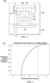
- FIG. 1 illustrates an example sensing and signaling control/monitoring system 100 and FIG. 2 is an example sensor assembly 200 that can be used with the sensing and signaling control/monitoring system 100.
- the sensing and signaling control/monitoring system 100 includes a contaminant detection subsystem 110 that measures a resonant frequency of a sensor assembly, a fault detection subsystem 130 that detects faults in the sensor assembly based on the change in the frequency of the sensor assembly, a cleaning subsystem 140 that provides a cleaning control signal to an actuator in the sensor assembly to expel contaminants from exposed surfaces of the sensor assembly, and a temperature monitoring/power regulation device 160 that monitors a temperature of the actuator.
- a controller 170 is provided to control the subsystems and devices via a bus 190.
- the example sensor assembly 200 illustrated in FIG. 2 is an example camera lens assembly for use on a camera.
- the sensor assembly 200 includes a housing 202 attached to a camera body 204, a sensing device (e.g., camera lens) 206 disposed in the housing 202, a transparent housing cover 208 disposed at an open end of the housing 202, and an actuator 210.
- the actuator 210 is disposed in the housing 202 and is attached to the housing cover 208.
- the actuator 210 includes electrodes 212 that allow the actuator 210 to be connected to the controller 170 via a circuit interface 214.
- the actuator 210 can be a transducer (e.g., piezoelectric cylindrical or ring type transducer) that when excited by proper signaling, will vibrate the housing cover 208. As described herein, by correctly adjusting the frequency and/or the amplitude of the vibration the contaminants can be expelled from an exposed surface 216 of the housing cover 208.
- a transducer e.g., piezoelectric cylindrical or ring type transducer
- the contaminant detection subsystem 110 detects and identifies contaminants disposed on an exposed surface of a sensor assembly (e.g., an exposed surface of a housing/lens cover) and can include a timer 112, a frequency measurement circuit 114, a frequency response measuring circuit 116, and a comparator 118.
- the contaminant detection subsystem 110 can be configured via the timer 112 to periodically check for contaminants based on various factors such as an amount of time the vehicle is in motion, a speed of the vehicle, direction of the vehicle (e.g., forward, reverse, turning), etc.
- the wait period can be dynamically updated (i.e. increased, decreased, no change) during the detection process.
- the contaminant detection subsystem 110 can be triggered manually (e.g., switch, push button, etc.) by an occupant of the vehicle.
- the contaminant detection subsystem 110 can be triggered by the sensor assembly if the sensor assembly senses that contaminants may be on the exposed surface.
- the triggering of the contaminant detection subsystem 110 can come from one of multiple sources.
- the frequency measurement circuit 114 monitors a change in a resonant frequency of the sensor assembly to detect the presence of contaminants disposed on the exposed surface of the sensor assembly.
- a shift in the resonant frequency indicates that contaminants are present on the exposed surface of the sensor assembly.
- ⁇ ⁇ n _ norm ⁇ ⁇ n ⁇ n is a normalized change in natural frequency
- ⁇ m norm ⁇ m m is a normalized change in mass both of which are unitless.
- FIG. 3 is an example plot 300 that illustrates a change in the normalized natural frequency versus a change in the normalized mass, as described hereinabove.
- the change in normalized natural frequency is very sensitive to a small change in normalized mass.
- a change in normalized mass of about 10% results in a change in normalized natural frequency of about 70%.
- the sensitivity of the change in the resonant or natural frequency is effective in detecting the presence of contaminants on the exposed surface. Detection of the contaminants can be detected at a first resonant frequency, a second resonant frequency, etc.
- the frequency response measurement circuit 116 measures a frequency response of the sensor assembly or any part thereof at a given resonant frequency to identify the type of contaminant and the amount of contaminant on the exposed surface.
- the frequency response of the sensor assembly plus the contaminants correlates to a specific amount of mass for contaminants on the exposed surface.
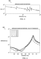
- FIG. 4 is an example frequency response, which shows the impedance magnitude response curve 400 for an example sensor assembly.
- the peak is a pole of the impedance magnitude response and the valley is a zero of the impedance magnitude response.
- the pole-zero pair represent a resonant frequency of the example sensor assembly. More specifically, the pole represents a parallel resonant frequency and the zero a series resonant frequency.
- FIG. 5 illustrates example impedance magnitude response curves 500 as a function of frequency for the example sensor assembly of FIG. 4 for different water droplet volumes ranging from 0 ⁇ L to 200 ⁇ L disposed in the center of the exposed surface of the example sensor assembly.
- a given resonant frequency will shift by different amounts based on the amount of water (or other contaminants) disposed on the exposed surface.
- the amount of frequency shift from the resonant frequency of the sensor assembly correlates to an amount of mass on the exposed surface.
- the contaminant detection subsystem 110 can be calibrated with the resonant frequencies and frequency responses of the sensor assembly and any and all likely contaminant mass levels that may come in contact with the exposed surface.
- This information can be stored in a database 180 and the comparator 118 compares the measured resonant frequencies and frequency responses with the stored resonant frequencies and frequency responses to determine the amount and/or type of contaminants on the exposed surface of the sensor assembly. Identification of the contaminants can be initialized at a first resonant frequency, a second resonant frequency, etc.
- the fault detection subsystem 130 performs system checks when the cleaning system 140 has not detected any appreciable mass on the exposed surface. System checks are performed by comparing a frequency response for a non-faulty, functional actuator and corresponding sensor assembly to a frequency response for a faulty, non-functional actuator and corresponding sensor assembly.
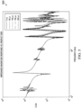
- FIG. 6 shows the impedance magnitude response for an example non-faulty, functioning (healthy) actuator and corresponding sensor assembly for different voltage excitation levels at around 300 kHz. The response has a zero between 285 and 295 kHz and a pole between 305 and 310 kHz, depending on the voltage excitation level.
- FIG. 6 shows the impedance magnitude response for an example non-faulty, functioning (healthy) actuator and corresponding sensor assembly for different voltage excitation levels at around 300 kHz. The response has a zero between 285 and 295 kHz and a pole between 305 and 310 kHz, depending on the voltage excitation level.
- the impedance magnitude response for an example faulty or damaged actuator and corresponding sensor assembly for different voltage excitation levels at around 300 kHz.
- the zero near 290 kHz no longer has a resonant effect when the voltage level increases to the required level to excite the actuator.
- the impedance magnitude response of the sensor assembly can be monitored periodically during the life of the actuator. If the response indicates that the resonant frequency is no longer present, then the actuator is faulty and the fault detection subsystem 130 disables a system start signal (described further hereinbelow).
- a faulty actuator that the fault detection subsystem 130 can detect by a frequency response is the de-polarization of the piezoelectric material in a piezoelectric transducer when the transducer overheats. This failure occurs when the temperature of the material exceeds its Curie temperature and occurs when too much current is driven thru the sensor assembly during the cleaning process. Other example failures may include a cracked or broken lens, transducer cracking, seal failure, epoxy failure, etc.
- the frequency response for the faulty actuator can be compared to the frequency response when the actuator is not faulty.
- the frequency response(s) for non-faulty actuators can be stored in a database 180 and accessed to compare the faulty actuator frequency responses to the non-faulty actuator frequency responses.
- the cleaning subsystem 140 initiates a cleaning process based on the identification of the contaminants by the contaminant detection subsystem 110.
- the cleaning subsystem 140 includes a cleaning mode selector 142, a cleaning phase selector 144, and a signal generation device 146.
- the cleaning mode selector 142 includes multiple cleaning modes (1, 2...N) and selects a cleaning mode based on the type of contaminant disposed on the exposed surface as determined by the contaminant detection subsystem 110 described hereinabove.
- a first cleaning mode may be implemented in response to determining the type of contaminants that correspond to mist
- a second cleaning mode may be implemented in response to determining the type of contaminants that correspond to water droplets
- a third cleaning mode may be implemented in response to determining the type of contaminants that correspond to ice, etc.
- Additional cleaning modes may correspond to other types of known (or unknown) types of contaminants such as dirt, mud, leaves, etc.
- the cleaning phase selector 144 selects a cleaning phase from multiple cleaning phases (A, B...N) within a given cleaning mode based on the amount (e.g., size, mass, weight, volume, etc.) of contaminant disposed on the exposed surface as determined by the contaminant detection subsystem 110 described hereinabove.
- each cleaning mode can include one or more different cleaning phases depending on the amount of contaminants.
- Each cleaning phase within a given cleaning mode can provide a different level, intensity or process of cleaning based on the amount of contaminants on the exposed surface.
- each cleaning phase can include one or more different parameters (i, ii...n) that define the cleaning process.
- the cleaning parameters can be defined as a frequency and/or voltage level that excites the actuator at specific resonant frequencies and/or amplitudes, which in turn vibrates the exposed surface thereby expelling contaminants from the exposed surface.
- Other parameters can include a time period (duration), heat drying, etc. Cleaning the exposed surface with ultrasonic systems and methods is disclosed in co-pending U.S. Pat. App. Serial No. 15/492,286, filed April 20, 2017 , entitled METHODS AND APPARATUS USING MULTISTAGE ULTRASONIC LENS CLEANING FOR IMPROVED WATER REMOVAL.
- each cleaning phase can provide a different process of cleaning. For example, larger amounts of contaminants disposed on the exposed surface require a more aggressive cleaning than smaller amounts.
- the phase selector 144 selects the cleaning phase that includes an appropriate number of cleaning parameters to efficiently expel the water from the exposed surface. More specifically, a first parameter can correspond to a first (high) frequency (e.g., about 300kHz) that vibrates the actuator and hence, the exposed surface to atomize large water droplets.
- a second parameter can correspond to a second (lower) frequency (e.g., about 25kHz) that vibrates the actuator to further expel smaller water droplets.
- a third parameter can correspond to using the transducer as a heating device to heat dry the remaining water droplets.
- the cleaning phase and/or the cleaning parameter can change accordingly, (e.g., from a more aggressive cleaning process to a lesser aggressive cleaning process (or vice versa)) to efficiently remove the contaminant from the exposed surface.
- the voltage and/or frequency or any other parameter can vary during the cleaning process.
- the signal generation device 146 generates a cleaning control signal 148 to an actuator via an actuator interface 150.
- the cleaning control signal 148 drives the actuator or other cleaning parameter based on the selected cleaning phase and/or cleaning parameters.
- the cleaning signal may have a predetermined frequency and/or voltage level that drives the actuator at the resonant frequency and/or amplitude to efficiently expel or dissipate the contaminants from the exposed surface.
- the cleaning signal can dynamically change as the cleaning mode, the cleaning phase, and/or the cleaning parameters dynamically change. As the contaminants begin to dissipate from the exposed surface, the resonant frequency of the exposed surface including the remaining contaminants changes. Thus during dissipation, the resonant frequency is essentially constantly changing.
- the cleaning mode, the cleaning phase and/or the cleaning parameters can change to continue efficient dissipation of the contaminants from the exposed surface that corresponds to the changing resonant frequency.
- the cleaning signal can be initiated at a first resonant frequency, a second resonant frequency, etc.
- the temperature monitoring device 160 monitors a temperature of the actuator and can also serve as a power regulation device to regulate power to the actuator. Because the actuator is connected (e.g., mechanically coupled) to the exposed surface, the temperature monitoring device consequently monitors a temperature of the exposed surface. If the temperature of the actuator and/or exposed surface exceeds a threshold temperature the cleaning process is stopped until the actuator and/or exposed surface cools to ambient temperature or below the threshold temperature. Cooling can be passive cooling (e.g., air cool) or active cooling (e.g., air jets, water spray, etc.). In some examples, the temperature can be monitored by an external device, such as a thermocouple, infrared sensor, etc.
- the temperature can be monitored internally by the sensor assembly.
- the temperature monitoring device 160 can determine the temperature of the actuator and/or sensor assembly by measuring a frequency response of the sensor assembly for different temperatures.
- FIG. 8 illustrates an example impedance magnitude response 800 for an example sensor assembly at different temperatures.
- the magnitude of the impedance response at a particular frequency e.g. 20kHz
- This information can be stored and can be accessed to determine the temperature of the actuator and if the temperature of the transducer exceeds a temperature safety threshold. If so, the cleaning process is stopped until the actuator and/or exposed surface cools to a safe operating temperature, which is below the threshold temperature.
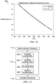
- FIG. 9 shows a close-up view of the impedance magnitude response 900 from 20 to 40 kHz.
- the temperature can easily be determined from the impedance data.
- FIG. 10 shows a plot 1000 that compares the temperate estimate using the linear equation and the actual temperature from the impedance magnitude plots.
- the maximum error in the estimated temperate is approximately 3.7°C.
- the controller 170 includes a microprocessor (microcontroller) 172 for executing instructions and/or algorithms to carry out the process of the sensing and signaling control/monitoring system 100.
- the microprocessor 172 can be embedded in a smart amplifier in a way such that the control system can be integrated into a single chip or can be comprised of multiple chips that are connected via bond wires.
- Logic control for the controller 170 can be software based (instructions executable by a processor core) or implemented as hardware, such as an arrangement of logic gates.
- the controller 170 may further include a data storage device 174 that may store data and/or instructions such as executable program code that is executed by the microprocessor 172.
- the data storage device 174 may store a number of applications and data that the microprocessor 172 can execute to implement at least the functionality described herein.
- the data storage device 174 may comprise various types of memory modules, including volatile and nonvolatile memory.
- the data storage device 174 can include one or more of random-access memory (RAM) 176, read-only memory (ROM) 178, flash solid state drive (SSD) (not shown), and a database 180.
- RAM random-access memory
- ROM read-only memory
- SSD flash solid state drive
- Additional devices and/or circuits 182 such as but not limited to pulse-width (PWM) switching controller(s), PWM pre-driver(s), amplifier(s), analog-to-digital convertor(s), multiplexor(s), etc. that facilitate execution of the signals regarding the actuator may be included.
- PWM pulse-width
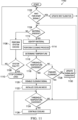
- FIG. 11 is flow diagram 1100 illustrating an example method of expelling the foreign contaminants from the exposed surface of the sensor assembly.
- the process begins in the contaminant subsystem described hereinabove.
- the sensing and signaling control/monitoring system waits a period of time (e.g., waits for the system start signal) before beginning the process.
- the frequency measurement device monitors the resonant frequency to determine whether contaminant(s) are present on the exposed surface. If no material is detected, then at 1106, the process proceeds to the fault detection subsystem where the sensing and signaling control/monitoring system undergoes a system check.
- a decision is made to determine whether the sensor assembly or any other component is faulty. If the system is faulty, then at 1110, the cleaning process stops. If the system is not faulty, the process loops back to 1102 and the process starts again.
- the contaminant detection subsystem 110 If at 1104 material is detected, the contaminant detection subsystem 110 generates a material detection signal, then at 1112 the frequency response measurement circuit identifies the type of contaminant disposed on the exposed surface.
- the process proceeds to the cleaning subsystem and the cleaning process is performed, which is further described below with reference to FIG. 12 .
- the temperature of the actuator is measured.
- a decision is made to determine whether the temperature of the actuator exceeds a temperature threshold. If "YES,” the process proceeds to the temperature monitoring subsystem where at 1120, the cleaning process is disabled.
- cooling of the actuator and/or exposed surface is initialized.
- a decision is made to determine whether the actuator temperature still exceeds the temperature threshold. If “YES,” then at 1126 the cooling continues and the process loops back to 1124. If “NO,” then the process starts again at 1102.
- FIG. 12 is flow diagram illustrating an example cleaning process represented as 1114 in FIG. 11 .
- the cleaning mode is determined based on the type of contaminant disposed on the exposed surface, as described hereinabove.
- the cleaning phase is determined based on an amount of contaminants disposed on the exposed surface.
- the cleaning parameters are set based on the phase selection.
- the cleaning signal is generated to thereby initialize the cleaning process.
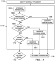
- FIG. 13 is a flow diagram illustrating another example cleaning process represented as 1114 in FIG. 11 .
- the contaminant identified on the exposed surface is ice and/or water.
- the temperature of the actuator is determined, which in turn determines the temperature of the exposed surface.
- a decision is made to determine whether the temperature is below freezing, which is an indication that ice has formed on the exposed surface. If "YES,” then a heating signal is generated to heat the exposed surface to thereby melt the ice. If "NO,” then at 1308 a decision is made to determine whether the amount of contaminant should be reduced.
- a cleaning signal is generated to excite the actuator at a resonant frequency of the exposed surface plus any contaminants on the exposed surface. If “NO,” then at 1312 a decision is made to determine whether drying is required based on the amount of contaminant. If “YES,” then at 1314 a heat signal is generated thereby heating the exposed surface of the sensor assembly. If “NO,” then the process loops back to 1102 and starts the process over again.
Landscapes
- Physics & Mathematics (AREA)
- General Physics & Mathematics (AREA)
- Pathology (AREA)
- Biochemistry (AREA)
- Immunology (AREA)
- Health & Medical Sciences (AREA)
- Life Sciences & Earth Sciences (AREA)
- Chemical & Material Sciences (AREA)
- Analytical Chemistry (AREA)
- General Health & Medical Sciences (AREA)
- Acoustics & Sound (AREA)
- Mechanical Engineering (AREA)
- Engineering & Computer Science (AREA)
- Optics & Photonics (AREA)
- Investigating Or Analyzing Materials By The Use Of Electric Means (AREA)
- Cleaning In General (AREA)
- Cleaning By Liquid Or Steam (AREA)
- Testing Or Calibration Of Command Recording Devices (AREA)
Claims (13)
- Steuerungssystem (100) für eine Sensoranordnung (200), das System (100) umfassend:ein Verunreinigungserkennungssubsystem zum Messen einer Resonanzfrequenz der Sensoranordnung (200),eine Sensoranordnung (200), die an einer Außenseite eines Fahrzeugs angeordnet ist, die Sensoranordnung (200) aufweisend ein Gehäuse, einen Aktor (210) und einen Sensor, die beide in dem Gehäuse angeordnet sind, und eine Gehäuseabdeckung, um dadurch eine Erfassung durch den Sensor durch diese hindurch zu ermöglichen, wobei das Verunreinigungserkennungssubsystem dazu eingerichtet ist, Verunreinigungen auf einer exponierten Oberfläche (216) der Gehäuseabdeckung zu erkennen und ein Erkennungssignal bereitzustellen, das Verunreinigungen auf der Gehäuseabdeckung basierend auf der Resonanzfrequenz der Sensoranordnung (200) identifiziert; undein Reinigungssubsystem zum Bereitstellen eines Reinigungssteuerungssignals an den Aktor (210), um die Verunreinigungen als Reaktion auf das Erkennungssignal von der Gehäuseabdeckung abzustoßen;wobei das Verunreinigungserkennungssubsystem einen Frequenzgangmesskreis zum Messen einer Änderung des Frequenzgangs der Sensoranordnung (200) aufweist, um eine Art der Verunreinigungen und die Menge der Verunreinigungen auf der Gehäuseabdeckung zu bestimmen; undferner umfassend eine Temperaturregelungsvorrichtung zum Regeln der Leistung des Aktors (210) basierend auf einer Temperatur des Aktors (210).
- System (100) nach Anspruch 1, wobei das Verunreinigungserkennungssubsystem einen Frequenzmesskreis zum Messen einer Änderung der Resonanzfrequenz der Sensoranordnung (200) aufweist, um ein Vorhandensein oder Nichtvorhandensein der Verunreinigungen auf der Gehäuseabdeckung zu bestimmen.
- System (100) nach Anspruch 1 oder 2, wobei das Reinigungssubsystem einen Reinigungsmoduswähler zum Auswählen eines Reinigungsmodus aus einer Mehrzahl von Reinigungsmodi basierend auf der Änderung der Resonanzfrequenz der Sensoranordnung (200) aufweist.
- System (100) nach Anspruch 3, wobei jeder Reinigungsmodus aus der Mehrzahl von Reinigungsmodi einen Reinigungsphasenwähler aufweist, um basierend auf der Änderung der Frequenzantwort der Sensoranordnung (200) eine Reinigungsphase aus einer Mehrzahl von Reinigungsphasen auszuwählen.
- System (100) nach Anspruch 4, wobei das Reinigungssubsystem dazu eingerichtet ist, das Reinigungssteuerungssignal an den Aktor (210) in Abhängigkeit von der Art der Verunreinigungen und/oder der Menge der Verunreinigungen bereitzustellen.
- System (100) nach Anspruch 5, wobei das Reinigungssubsystem dazu eingerichtet ist, das Reinigungssteuerungssignal zur Anpassung der Vibrationsamplitude und Anregungsfrequenz an den Aktor (210) bereitzustellen, basierend auf mindestens eines von der Art der Verunreinigungen und der Menge der Verunreinigungen.
- System (100) nach Anspruch 6, wobei die Art und Menge der Verunreinigungen bei einer ersten Resonanzfrequenz erkannt werden und das Reinigungssteuerungssignal bei einer zweiten Resonanzfrequenz der Sensoranordnung (200) ausgelöst wird.
- System (100) nach einem der Ansprüche 1 bis 7, ferner umfassend eine Fehlererkennungsvorrichtung zur Erkennung von Fehlern in der Sensoranordnung (200) basierend auf der Änderung der Frequenzantwort der Sensoranordnung (200) bei unterschiedlichen Spannungsanregungspegeln, um zu bestimmen, ob die Resonanzfrequenz der Sensoranordnung (200) bei den unterschiedlichen Spannungsanregungspegeln vorhanden ist, um zu bestimmen, ob die Sensoranordnung (200) fehlerhaft ist, und um das Systemstartsignal zu deaktivieren, wenn ein Fehler erkannt wird.
- System (100) nach einem der Ansprüche 1 bis 8, wobei die Temperaturregelungsvorrichtung dazu ausgebildet ist, basierend auf der Änderung der Frequenzantwort der Sensoranordnung (200) zu bestimmen, ob eine Temperatur des Aktors (210) einen Temperaturschwellenwert überschreitet, und das Reinigungssteuerungssignal zu deaktivieren und einen Kühlvorgang auszulösen, wenn die Temperatur des Aktors (210) den Temperaturschwellenwert überschreitet.
- System (100) nach Anspruch 1, wobei die Temperaturregelungsvorrichtung dazu ausgebildet ist, eine Temperatur des Verunreinigungserkennungssubsystems und/oder der Sensoranordnung (200) zu regeln, wobei das Verunreinigungserkennungssubsystem dazu eingerichtet ist, die Amplitude und Frequenz der Vibration des Aktors (210) in Abhängigkeit von der Temperatur des Verunreinigungserkennungssubsystem und der Resonanzfrequenz der Sensoranordnung (200) zu steuern.
- Verunreinigungserfassungssystem, umfassend:eine Sensoranordnung (200), die an einer Außenseite eines Fahrzeugs angeordnet ist, wobei die Sensoranordnung (200) einen Aktor (210) und einen Sensor aufweist, die beide in einem Gehäuse angeordnet sind, um eine Erfassung durch den Sensor durch das Gehäuse zu ermöglichen;ein Verunreinigungserkennungssubsystem zum Messen einer Resonanzfrequenz der Sensoranordnung (200), wobei das Verunreinigungserkennungssubsystem ein Erkennungssignal als Reaktion auf die Erkennung von Verunreinigungen auf einer exponierten Oberfläche (216) des Gehäuses bereitstellt;ein Reinigungssubsystem zum Implementieren eines Abstoßens der Verunreinigungen von der exponierten Oberfläche (216) als Reaktion auf das Erkennungssignal; undeine Temperaturregelungsvorrichtung zum Regeln der Leistung des Aktors (210) basierend auf einer Temperatur des Aktors (210).
- Verfahren zum Abstoßen von Verunreinigungen von einem Sensor, das Verfahren umfassend:Messen einer Änderung einer Resonanzfrequenz einer Sensoranordnung (200), um Verunreinigungen auf einer exponierten Oberfläche (216) der Sensoranordnung (200) zu erkennen;Messen einer Änderung der Frequenzantwort der Sensoranordnung (200), um das Vorhandensein und die Menge von Verunreinigungen auf der exponierten Oberfläche (216) zu bestimmen;Bestimmen eines Reinigungsmodus basierend auf der Menge der Verunreinigungen auf der exponierten Oberfläche (216);Bestimmen einer Reinigungsphase basierend auf der Menge der Verunreinigungen auf der exponierten Oberfläche (216);Erzeugen eines Reinigungssteuerungssignals an einen Aktor (210) der Sensoranordnung (200), um die Verunreinigungen von der exponierten Oberfläche (216) abzustoßen; undBestimmen, ob eine Temperatur des Aktors (210) einen Temperaturschwellenwert überschreitet, basierend auf der Änderung der Frequenzantwort der Sensoranordnung (200), Deaktivieren des Reinigungssteuerungssignals, wenn die Temperatur des Aktors (210) den Temperaturschwellenwert überschreitet, und Auslösen eines Kühlvorgangs zum Kühlen des Aktors (210).
- Verfahren nach Anspruch 12, ferner umfassend Vibrieren des Aktors (210) bei einer Resonanzfrequenz der Sensoranordnung (200), um die Verunreinigungen von der exponierten Oberfläche (216) abzustoßen.
Priority Applications (1)
| Application Number | Priority Date | Filing Date | Title |
|---|---|---|---|
| EP24218906.6A EP4535976A3 (de) | 2017-02-03 | 2018-02-02 | Steuerungssystem für eine sensoranordnung |
Applications Claiming Priority (3)
| Application Number | Priority Date | Filing Date | Title |
|---|---|---|---|
| US201762454154P | 2017-02-03 | 2017-02-03 | |
| US15/605,463 US10695805B2 (en) | 2017-02-03 | 2017-05-25 | Control system for a sensor assembly |
| PCT/US2018/016714 WO2018144924A1 (en) | 2017-02-03 | 2018-02-02 | Control system for a sensor assembly |
Related Child Applications (1)
| Application Number | Title | Priority Date | Filing Date |
|---|---|---|---|
| EP24218906.6A Division EP4535976A3 (de) | 2017-02-03 | 2018-02-02 | Steuerungssystem für eine sensoranordnung |
Publications (3)
| Publication Number | Publication Date |
|---|---|
| EP3577451A1 EP3577451A1 (de) | 2019-12-11 |
| EP3577451A4 EP3577451A4 (de) | 2020-07-29 |
| EP3577451B1 true EP3577451B1 (de) | 2024-12-18 |
Family
ID=63038266
Family Applications (2)
| Application Number | Title | Priority Date | Filing Date |
|---|---|---|---|
| EP24218906.6A Pending EP4535976A3 (de) | 2017-02-03 | 2018-02-02 | Steuerungssystem für eine sensoranordnung |
| EP18747814.4A Active EP3577451B1 (de) | 2017-02-03 | 2018-02-02 | Steuerungssystem für eine sensoranordnung |
Family Applications Before (1)
| Application Number | Title | Priority Date | Filing Date |
|---|---|---|---|
| EP24218906.6A Pending EP4535976A3 (de) | 2017-02-03 | 2018-02-02 | Steuerungssystem für eine sensoranordnung |
Country Status (4)
| Country | Link |
|---|---|
| US (2) | US10695805B2 (de) |
| EP (2) | EP4535976A3 (de) |
| CN (1) | CN110234989B (de) |
| WO (1) | WO2018144924A1 (de) |
Families Citing this family (35)
| Publication number | Priority date | Publication date | Assignee | Title |
|---|---|---|---|---|
| US10384239B2 (en) | 2016-09-27 | 2019-08-20 | Texas Instruments Incorporated | Methods and apparatus for ultrasonic lens cleaner using configurable filter banks |
| WO2018100796A1 (ja) * | 2016-11-30 | 2018-06-07 | 株式会社村田製作所 | 振動装置、カメラ用水滴除去装置及びカメラ |
| EP3453459A1 (de) * | 2017-09-06 | 2019-03-13 | Siemens Aktiengesellschaft | Verfahren zum betrieb einer anlage, anlage und computerprogrammprodukt |
| WO2019130623A1 (ja) * | 2017-12-27 | 2019-07-04 | 株式会社村田製作所 | 振動装置及び光学検出装置 |
| US20190210570A1 (en) * | 2018-01-08 | 2019-07-11 | Ford Global Technologies, Llc | Sensor cleaning and cooling |
| US10766464B2 (en) * | 2018-03-09 | 2020-09-08 | Ford Global Technologies, Llc | Sensor cleaning and thermal control |
| DE102018221868B4 (de) * | 2018-12-17 | 2022-09-08 | Volkswagen Aktiengesellschaft | Vorrichtung und Verfahren zur Kühlung mindestens einer Oberfläche und/oder mindestens eines Volumens eines Sensors eines Fahrzeugs |
| US10908132B2 (en) | 2019-01-07 | 2021-02-02 | Goodrich Corporation | Real-time performance and health monitoring of ice detector systems and estimation of remaining useful life |
| EP3715826B1 (de) * | 2019-03-26 | 2024-03-06 | Infineon Technologies AG | Sensorvorrichtung, partikelsensorvorrichtung und verfahren zur detektion der dichte eines partikelförmigen materials |
| US12198605B2 (en) | 2019-03-29 | 2025-01-14 | Creeled, Inc. | Active control of light emitting diodes and light emitting diode displays |
| US11790831B2 (en) * | 2019-03-29 | 2023-10-17 | Creeled, Inc. | Active control of light emitting diodes and light emitting diode displays |
| US12142716B2 (en) | 2019-03-29 | 2024-11-12 | Creeled, Inc. | Active control of light emitting diodes and light emitting diode displays |
| US11727857B2 (en) | 2019-03-29 | 2023-08-15 | Creeled, Inc. | Active control of light emitting diodes and light emitting diode displays |
| US11694601B2 (en) | 2019-03-29 | 2023-07-04 | Creeled, Inc. | Active control of light emitting diodes and light emitting diode displays |
| US11776460B2 (en) | 2019-03-29 | 2023-10-03 | Creeled, Inc. | Active control of light emitting diodes and light emitting diode displays |
| FR3100998B1 (fr) * | 2019-09-25 | 2022-06-03 | Lille Ecole Centrale | Dispositif pour nettoyer un support recouvert d’un liquide |
| DE102019128392A1 (de) * | 2019-10-21 | 2021-04-22 | Webasto SE | Dachmodul mit Umfeldsensor und Sensorabdeckung |
| CN110841996A (zh) * | 2019-12-17 | 2020-02-28 | 北京万集科技股份有限公司 | 激光雷达的清洁装置、方法、设备及存储介质 |
| US11695102B2 (en) | 2020-06-19 | 2023-07-04 | Creeled, Inc. | Active electrical elements with light-emitting diodes |
| US12240419B2 (en) * | 2020-06-30 | 2025-03-04 | Tusimple, Inc. | Autonomous driving camera cleaning system |
| DE102020128903B4 (de) | 2020-11-03 | 2023-11-09 | Marelli Automotive Lighting Reutlingen (Germany) GmbH | Sensorvorrichtung, Scheinwerfer, teilautonomes Kraftfahrzeug und Verfahren |
| FR3117384B1 (fr) * | 2020-12-14 | 2026-01-23 | Centrale Lille Inst | Dispositif pour nettoyer une surface optique |
| FR3117385B1 (fr) * | 2020-12-14 | 2024-06-28 | Univ Lille | Dispositif pour nettoyer une surface optique |
| CN113687311B (zh) * | 2021-09-01 | 2024-04-02 | 安徽城宜防务科技有限责任公司 | 一种用于坝体监测的雷达装置 |
| EP4476714A1 (de) | 2022-02-07 | 2024-12-18 | Creeled, Inc. | Leuchtdioden mit gemischter taktbereichssignalisierung |
| US12014673B2 (en) | 2022-02-07 | 2024-06-18 | Creeled, Inc. | Light-emitting diodes with mixed clock domain signaling |
| CN115092095A (zh) * | 2022-06-21 | 2022-09-23 | 珠海市魅族科技有限公司 | 传感器清洁方法、装置、设备及可读存储介质 |
| CN115327973B (zh) * | 2022-07-21 | 2023-10-27 | 阿波罗智能技术(北京)有限公司 | 一种清洁装置、设备、电子设备和自动驾驶车辆 |
| CN115468628A (zh) * | 2022-07-22 | 2022-12-13 | 大庆飞海石油科技有限公司 | 一种油田用带隔离保护结构的液位计 |
| KR20240029443A (ko) | 2022-08-26 | 2024-03-05 | 삼성전자주식회사 | 센서 장치 및 센서 장치의 작동 방법 |
| CN115815215A (zh) * | 2022-11-08 | 2023-03-21 | 乳源东阳光智能科技有限公司 | 一种加热组件及其坐便器和加热组件清洗方法 |
| CN116274166A (zh) * | 2023-03-03 | 2023-06-23 | 首钢智新迁安电磁材料有限公司 | 一种阳极光阑的清洁方法和扫描电镜 |
| US12014677B1 (en) | 2023-04-10 | 2024-06-18 | Creeled, Inc. | Light-emitting diode packages with transformation and shifting of pulse width modulation signals and related methods |
| US12526889B2 (en) | 2023-08-29 | 2026-01-13 | Creeled, Inc. | Light-emitting diode packages with varying current pulse width modulation and related methods |
| US12437707B2 (en) | 2023-09-27 | 2025-10-07 | Creeled, Inc. | Pseudo-exponential encoding for light-emitting devices and related methods |
Family Cites Families (75)
| Publication number | Priority date | Publication date | Assignee | Title |
|---|---|---|---|---|
| US3681626A (en) | 1971-11-11 | 1972-08-01 | Branson Instr | Oscillatory circuit for ultrasonic cleaning apparatus |
| SE436675B (sv) | 1975-08-12 | 1985-01-14 | Ki Politekhnichsky I Im 50 Let | Elektrisk motor driven genom piezoelektriska krafter |
| JPS568688A (en) | 1979-07-05 | 1981-01-29 | Nisshin Flour Milling Co Ltd | Antitumor substance 1166a and its preparation |
| US4271371A (en) | 1979-09-26 | 1981-06-02 | Kabushiki Kaisha Morita Seisakusho | Driving system for an ultrasonic piezoelectric transducer |
| US4556467A (en) | 1981-06-22 | 1985-12-03 | Mineral Separation Corporation | Apparatus for ultrasonic processing of materials |
| DE3430605A1 (de) | 1984-08-20 | 1986-02-27 | Siemens AG, 1000 Berlin und 8000 München | Verfahren und vorrichtung zur reinigung, desinfektion und sterilisation von aerztlichen, insbesondere zahnaerztlichen, instrumenten |
| GB8421836D0 (en) | 1984-08-29 | 1984-10-03 | Smc Metal Tech Co Ltd | Contact lens cleaning apparatus |
| US4691725A (en) | 1985-05-13 | 1987-09-08 | Ultramed Corporation | Lens cleaner |
| US4852592A (en) | 1987-08-13 | 1989-08-01 | Digangi And Ross | Apparatus for the cleaning of contact lenses |
| JPH06103678B2 (ja) | 1987-11-28 | 1994-12-14 | 株式会社東芝 | 半導体基板の加工方法 |
| US4836684A (en) | 1988-02-18 | 1989-06-06 | Ultrasonic Power Corporation | Ultrasonic cleaning apparatus with phase diversifier |
| JP2650303B2 (ja) * | 1988-02-25 | 1997-09-03 | アイシン精機株式会社 | ミラーのクリーニング装置 |
| US4870982A (en) | 1989-01-09 | 1989-10-03 | Tatung Company Of America, Inc. | Ultrasonic cleaning apparatus for household use |
| US5005015A (en) | 1989-08-07 | 1991-04-02 | General Electric Company | Ice detection system |
| US5113116A (en) | 1989-10-05 | 1992-05-12 | Firma J. Eberspacher | Circuit arrangement for accurately and effectively driving an ultrasonic transducer |
| US5178173A (en) | 1991-08-01 | 1993-01-12 | Robert J. Pace | Ultrasonic contact lens cleaning device |
| US5706840A (en) * | 1995-03-03 | 1998-01-13 | Sandia Corporation | Precision cleaning apparatus and method |
| US5853500A (en) * | 1997-07-18 | 1998-12-29 | Symetrix Corporation | Method for fabricating thin films of barium strontium titanate without exposure to oxygen at high temperatures |
| US6064259A (en) | 1998-07-24 | 2000-05-16 | Nikon Corporation Of America | High power, high performance pulse width modulation amplifier |
| GB9925373D0 (en) * | 1999-10-27 | 1999-12-29 | Schlumberger Ltd | Downhole instrumentation and cleaning system |
| US7215372B2 (en) * | 2002-05-17 | 2007-05-08 | Olympus Corporation | Optical apparatus having dust off function |
| US6607606B2 (en) | 2001-04-03 | 2003-08-19 | Hewlett-Packard Development Company, L.P. | Self-cleaning lens shield |
| DE20302419U1 (de) * | 2003-02-14 | 2003-04-24 | Schlosser, Stefan, 89264 Weißenhorn | Anordnung zur Detektion von Verschmutzungen auf Oberflächen eines Glases |
| US7723899B2 (en) | 2004-02-03 | 2010-05-25 | S.C. Johnson & Son, Inc. | Active material and light emitting device |
| US7538473B2 (en) | 2004-02-03 | 2009-05-26 | S.C. Johnson & Son, Inc. | Drive circuits and methods for ultrasonic piezoelectric actuators |
| JP4585883B2 (ja) | 2005-02-18 | 2010-11-24 | 株式会社東海理化電機製作所 | パワーウインドウ装置 |
| US7742167B2 (en) | 2005-06-17 | 2010-06-22 | Perkinelmer Health Sciences, Inc. | Optical emission device with boost device |
| US20070003081A1 (en) | 2005-06-30 | 2007-01-04 | Insound Medical, Inc. | Moisture resistant microphone |
| US7799137B2 (en) * | 2005-07-15 | 2010-09-21 | Stokely-Van Camp, Inc. | Resonant frequency bottle sanitation |
| GB2435133A (en) * | 2006-02-08 | 2007-08-15 | Dyson Technology Ltd | Agitation source controller |
| US8136952B2 (en) | 2007-02-20 | 2012-03-20 | Canon Kabushiki Kaisha | Image capturing apparatus |
| US8137087B2 (en) | 2007-04-05 | 2012-03-20 | Ricoh Company, Ltd. | Toner preparation method and apparatus, and toner prepared thereby |
| US9070856B1 (en) | 2007-06-14 | 2015-06-30 | Misonix, Incorporated | Waveform generator for driving electromechanical device |
| JP4631921B2 (ja) * | 2008-03-26 | 2011-02-16 | ソニー株式会社 | 圧電素子の駆動装置および圧電素子駆動周波数の制御方法 |
| JP2009283069A (ja) | 2008-05-22 | 2009-12-03 | Kenwood Corp | 光ディスク装置、クリーニング方法及びプログラム |
| US7705517B1 (en) | 2008-10-30 | 2010-04-27 | Texas Instruments Incorporated | Ultrasound transmitter |
| US8854505B2 (en) | 2008-11-13 | 2014-10-07 | Nikon Corporation | Dust-removal optical device, a dust-removal imaging device, and method of manufacturing an optical device for removing dust |
| KR20110139720A (ko) | 2009-03-09 | 2011-12-29 | 유니벤처, 인크. | 액체로부터 입자를 분리하기 위한 방법 및 장치 |
| US8293026B1 (en) | 2009-04-28 | 2012-10-23 | Integrated Medical Systems International, Inc. | Fixtures for the cleaning of lenses |
| KR101721278B1 (ko) | 2009-09-04 | 2017-03-29 | 닛토덴코 가부시키가이샤 | 마이크로폰용 통음막과 그것을 구비하는 마이크로폰용 통음막 부재, 마이크로폰 및 마이크로폰을 구비하는 전자 기기 |
| JP5056919B2 (ja) | 2009-09-29 | 2012-10-24 | 株式会社デンソー | 車載光学センサカバー及び車載光学センサ装置 |
| JP5530327B2 (ja) | 2010-10-06 | 2014-06-25 | 中村科学工業株式会社 | プラスチック材料の水分除去方法 |
| JP5725882B2 (ja) | 2011-01-25 | 2015-05-27 | キヤノン株式会社 | 異物除去ユニットおよびそれを備える光学機器 |
| EP2683176B1 (de) | 2011-03-03 | 2020-06-17 | Nitto Denko Corporation | Wasserdichter tonübertragender film und elektrisches produkt |
| JP5693310B2 (ja) * | 2011-03-17 | 2015-04-01 | キヤノン株式会社 | 異物除去装置およびそれを備える光学機器 |
| US8899761B2 (en) | 2011-03-23 | 2014-12-02 | Gentex Corporation | Lens cleaning apparatus |
| US9252685B2 (en) | 2011-10-20 | 2016-02-02 | Canon Kabushiki Kaisha | Dust removing device and imaging device |
| KR20130076250A (ko) | 2011-12-28 | 2013-07-08 | 삼성전자주식회사 | 스피커 장치를 위한 공명 구조를 갖는 전자 장치 |
| US9796359B2 (en) * | 2012-02-23 | 2017-10-24 | The Raymond Corporation | Method and apparatus for removing and preventing lens surface contamination on a vehicle lens |
| KR20130104138A (ko) | 2012-03-13 | 2013-09-25 | 삼성전자주식회사 | 휴대용 단말기의 방수 케이스 |
| JP5885552B2 (ja) * | 2012-03-21 | 2016-03-15 | キヤノン株式会社 | 振動装置、該振動装置を有する駆動装置、及び光学機器 |
| EP2873572B1 (de) | 2012-07-11 | 2017-05-10 | Nissan Motor Co., Ltd. | Reinigungsvorrichtung für fahrzeugmontierte kamera, und reinigungsverfahren für fahrzeugmontierte kamera |
| US9436005B2 (en) | 2012-08-02 | 2016-09-06 | Gentex Corporation | Amplified piezoelectric camera lens cleaner |
| US9084053B2 (en) | 2013-01-11 | 2015-07-14 | Red Tail Hawk Corporation | Microphone environmental protection device |
| TWM456008U (zh) | 2013-02-01 | 2013-06-21 | Cho-Yi Lin | 電子裝置及其防塵蓋 |
| US9335355B2 (en) | 2013-03-06 | 2016-05-10 | Apple Inc. | Electronic device with liquid contact sensors |
| US9519021B2 (en) | 2013-03-11 | 2016-12-13 | Covidien Lp | Systems and methods for detecting abnormalities within a circuit of an electrosurgical generator |
| CN103191886B (zh) * | 2013-03-21 | 2015-04-08 | 安徽师范大学 | 一种利用超声波检测表面污染程度并清洗的方法 |
| US9880061B2 (en) * | 2013-06-14 | 2018-01-30 | Hrl Laboratories, Llc | Methods and apparatus for sensing the internal temperature of an electrochemical device |
| US9568727B2 (en) | 2014-03-25 | 2017-02-14 | Amazon Technologies, Inc. | Electrowetting display pixel architecture |
| US9226076B2 (en) | 2014-04-30 | 2015-12-29 | Apple Inc. | Evacuation of liquid from acoustic space |
| US9573165B2 (en) | 2014-08-22 | 2017-02-21 | Apple Inc. | Hydrophobic mesh cover |
| RU2017125548A (ru) * | 2014-12-19 | 2019-01-22 | Майкро Моушн, Инк. | Управление колебаниями вибродатчика на основании фазового рассогласования |
| US10401618B2 (en) | 2015-03-11 | 2019-09-03 | Texas Instruments Incorporated | Ultrasonic lens cleaning system with current sensing |
| KR101851435B1 (ko) | 2015-12-07 | 2018-04-23 | 명지대학교 산학협력단 | 카메라 렌즈부를 클리닝하는 장치 및 방법 |
| WO2017110563A1 (ja) | 2015-12-24 | 2017-06-29 | 株式会社村田製作所 | 振動装置及びその駆動方法並びにカメラ |
| EP3460460B1 (de) | 2016-05-18 | 2024-02-28 | Myongji University Industry and Academia Cooperation Foundation | Reinigungsvorrichtung und -verfahren |
| US10071400B2 (en) | 2016-06-20 | 2018-09-11 | Texas Instruments Incorporated | Ultrasonic lens cleaning with travelling wave excitation |
| US10384239B2 (en) | 2016-09-27 | 2019-08-20 | Texas Instruments Incorporated | Methods and apparatus for ultrasonic lens cleaner using configurable filter banks |
| US10682675B2 (en) | 2016-11-01 | 2020-06-16 | Texas Instruments Incorporated | Ultrasonic lens cleaning system with impedance monitoring to detect faults or degradation |
| WO2018169233A1 (en) | 2017-03-14 | 2018-09-20 | Lg Electronics Inc. | Device for cleaning surface using electrowetting element and method for controlling the same |
| US11607704B2 (en) | 2017-04-20 | 2023-03-21 | Texas Instruments Incorporated | Methods and apparatus for electrostatic control of expelled material for lens cleaners |
| US10780467B2 (en) | 2017-04-20 | 2020-09-22 | Texas Instruments Incorporated | Methods and apparatus for surface wetting control |
| US10908414B2 (en) | 2017-05-10 | 2021-02-02 | Texas Instruments Incorporated | Lens cleaning via electrowetting |
| US10527843B2 (en) | 2017-05-12 | 2020-01-07 | International Business Machines Corporation | Ultra-sonic self-cleaning system |
-
2017
- 2017-05-25 US US15/605,463 patent/US10695805B2/en active Active
-
2018
- 2018-02-02 EP EP24218906.6A patent/EP4535976A3/de active Pending
- 2018-02-02 WO PCT/US2018/016714 patent/WO2018144924A1/en not_active Ceased
- 2018-02-02 EP EP18747814.4A patent/EP3577451B1/de active Active
- 2018-02-02 CN CN201880009347.9A patent/CN110234989B/zh active Active
-
2020
- 2020-06-29 US US16/915,704 patent/US20200324324A1/en not_active Abandoned
Also Published As
| Publication number | Publication date |
|---|---|
| WO2018144924A1 (en) | 2018-08-09 |
| US10695805B2 (en) | 2020-06-30 |
| CN110234989A (zh) | 2019-09-13 |
| EP3577451A4 (de) | 2020-07-29 |
| EP4535976A3 (de) | 2025-06-11 |
| US20200324324A1 (en) | 2020-10-15 |
| EP3577451A1 (de) | 2019-12-11 |
| US20180221921A1 (en) | 2018-08-09 |
| EP4535976A2 (de) | 2025-04-09 |
| CN110234989B (zh) | 2023-01-03 |
Similar Documents
| Publication | Publication Date | Title |
|---|---|---|
| EP3577451B1 (de) | Steuerungssystem für eine sensoranordnung | |
| US11467396B2 (en) | Cleaning device, and image capturing apparatus including cleaning device | |
| US11366076B2 (en) | Transducer temperature sensing | |
| US10682675B2 (en) | Ultrasonic lens cleaning system with impedance monitoring to detect faults or degradation | |
| US11042026B2 (en) | Transducer-induced heating and cleaning | |
| US11979669B2 (en) | Cleaning device, imaging unit including the same, and cleaning method | |
| US20150138359A1 (en) | In-vehicle camera control device | |
| US20180243804A1 (en) | Transducer-induced heating-facilitated cleaning | |
| CN105308476B (zh) | 基于超声的测量传感器和用于运行基于超声的测量传感器的方法 | |
| CN112368595B (zh) | 测距装置 | |
| US20200282435A1 (en) | Ultrasonic lens cleaning systems and methods | |
| US20250281948A1 (en) | Method for Detecting Dirt and Cleaning with Piezo Transducer, Device, Automotive Part and Vehicle | |
| JP7548408B2 (ja) | 物体検知システム | |
| JP2009501505A (ja) | 電磁アクチュエータの駆動制御のための装置及び電磁アクチュエータの最初のインダクタンスの検査方法 | |
| JP7722551B2 (ja) | 振動装置及び振動方法 | |
| JPH078125U (ja) | 水滴除去制御装置 |
Legal Events
| Date | Code | Title | Description |
|---|---|---|---|
| STAA | Information on the status of an ep patent application or granted ep patent |
Free format text: STATUS: THE INTERNATIONAL PUBLICATION HAS BEEN MADE |
|
| PUAI | Public reference made under article 153(3) epc to a published international application that has entered the european phase |
Free format text: ORIGINAL CODE: 0009012 |
|
| STAA | Information on the status of an ep patent application or granted ep patent |
Free format text: STATUS: REQUEST FOR EXAMINATION WAS MADE |
|
| 17P | Request for examination filed |
Effective date: 20190903 |
|
| AK | Designated contracting states |
Kind code of ref document: A1 Designated state(s): AL AT BE BG CH CY CZ DE DK EE ES FI FR GB GR HR HU IE IS IT LI LT LU LV MC MK MT NL NO PL PT RO RS SE SI SK SM TR |
|
| AX | Request for extension of the european patent |
Extension state: BA ME |
|
| RIC1 | Information provided on ipc code assigned before grant |
Ipc: B06B 1/06 20060101ALI20200124BHEP Ipc: H01L 41/04 20060101ALI20200124BHEP Ipc: G01N 29/02 20060101ALI20200124BHEP Ipc: G01N 29/12 20060101AFI20200124BHEP Ipc: G01D 3/00 20060101ALI20200124BHEP Ipc: G01N 29/036 20060101ALI20200124BHEP Ipc: B08B 7/02 20060101ALI20200124BHEP Ipc: B60S 1/56 20060101ALI20200124BHEP |
|
| DAV | Request for validation of the european patent (deleted) | ||
| DAX | Request for extension of the european patent (deleted) | ||
| A4 | Supplementary search report drawn up and despatched |
Effective date: 20200630 |
|
| RIC1 | Information provided on ipc code assigned before grant |
Ipc: B08B 7/02 20060101ALI20200624BHEP Ipc: B60S 1/56 20060101ALI20200624BHEP Ipc: G01D 3/00 20060101ALI20200624BHEP Ipc: B06B 1/06 20060101ALI20200624BHEP Ipc: H01L 41/04 20060101ALI20200624BHEP Ipc: G01N 29/12 20060101AFI20200624BHEP Ipc: G01N 29/02 20060101ALI20200624BHEP Ipc: G02B 27/00 20060101ALI20200624BHEP Ipc: G01N 29/036 20060101ALI20200624BHEP |
|
| STAA | Information on the status of an ep patent application or granted ep patent |
Free format text: STATUS: EXAMINATION IS IN PROGRESS |
|
| 17Q | First examination report despatched |
Effective date: 20221109 |
|
| GRAP | Despatch of communication of intention to grant a patent |
Free format text: ORIGINAL CODE: EPIDOSNIGR1 |
|
| STAA | Information on the status of an ep patent application or granted ep patent |
Free format text: STATUS: GRANT OF PATENT IS INTENDED |
|
| RIC1 | Information provided on ipc code assigned before grant |
Ipc: H10N 30/80 20230101ALI20240621BHEP Ipc: G02B 27/00 20060101ALI20240621BHEP Ipc: G01N 29/036 20060101ALI20240621BHEP Ipc: B60S 1/56 20060101ALI20240621BHEP Ipc: G01N 29/02 20060101ALI20240621BHEP Ipc: B06B 1/06 20060101ALI20240621BHEP Ipc: B08B 7/02 20060101ALI20240621BHEP Ipc: G01D 3/00 20060101ALI20240621BHEP Ipc: G01N 29/12 20060101AFI20240621BHEP |
|
| INTG | Intention to grant announced |
Effective date: 20240712 |
|
| RIN1 | Information on inventor provided before grant (corrected) |
Inventor name: FEDIGAN, STEPHEN JOHN Inventor name: MAGEE, DAVID, PATRICK |
|
| GRAS | Grant fee paid |
Free format text: ORIGINAL CODE: EPIDOSNIGR3 |
|
| GRAA | (expected) grant |
Free format text: ORIGINAL CODE: 0009210 |
|
| STAA | Information on the status of an ep patent application or granted ep patent |
Free format text: STATUS: THE PATENT HAS BEEN GRANTED |
|
| P01 | Opt-out of the competence of the unified patent court (upc) registered |
Free format text: CASE NUMBER: APP_56046/2024 Effective date: 20241014 |
|
| AK | Designated contracting states |
Kind code of ref document: B1 Designated state(s): AL AT BE BG CH CY CZ DE DK EE ES FI FR GB GR HR HU IE IS IT LI LT LU LV MC MK MT NL NO PL PT RO RS SE SI SK SM TR |
|
| REG | Reference to a national code |
Ref country code: GB Ref legal event code: FG4D |
|
| REG | Reference to a national code |
Ref country code: CH Ref legal event code: EP |
|
| REG | Reference to a national code |
Ref country code: DE Ref legal event code: R096 Ref document number: 602018077704 Country of ref document: DE |
|
| REG | Reference to a national code |
Ref country code: IE Ref legal event code: FG4D |
|
| REG | Reference to a national code |
Ref country code: LT Ref legal event code: MG9D |
|
| PG25 | Lapsed in a contracting state [announced via postgrant information from national office to epo] |
Ref country code: HR Free format text: LAPSE BECAUSE OF FAILURE TO SUBMIT A TRANSLATION OF THE DESCRIPTION OR TO PAY THE FEE WITHIN THE PRESCRIBED TIME-LIMIT Effective date: 20241218 |
|
| PG25 | Lapsed in a contracting state [announced via postgrant information from national office to epo] |
Ref country code: FI Free format text: LAPSE BECAUSE OF FAILURE TO SUBMIT A TRANSLATION OF THE DESCRIPTION OR TO PAY THE FEE WITHIN THE PRESCRIBED TIME-LIMIT Effective date: 20241218 |
|
| PG25 | Lapsed in a contracting state [announced via postgrant information from national office to epo] |
Ref country code: BG Free format text: LAPSE BECAUSE OF FAILURE TO SUBMIT A TRANSLATION OF THE DESCRIPTION OR TO PAY THE FEE WITHIN THE PRESCRIBED TIME-LIMIT Effective date: 20241218 |
|
| PG25 | Lapsed in a contracting state [announced via postgrant information from national office to epo] |
Ref country code: NO Free format text: LAPSE BECAUSE OF FAILURE TO SUBMIT A TRANSLATION OF THE DESCRIPTION OR TO PAY THE FEE WITHIN THE PRESCRIBED TIME-LIMIT Effective date: 20250318 |
|
| REG | Reference to a national code |
Ref country code: NL Ref legal event code: MP Effective date: 20241218 |
|
| PG25 | Lapsed in a contracting state [announced via postgrant information from national office to epo] |
Ref country code: LV Free format text: LAPSE BECAUSE OF FAILURE TO SUBMIT A TRANSLATION OF THE DESCRIPTION OR TO PAY THE FEE WITHIN THE PRESCRIBED TIME-LIMIT Effective date: 20241218 Ref country code: GR Free format text: LAPSE BECAUSE OF FAILURE TO SUBMIT A TRANSLATION OF THE DESCRIPTION OR TO PAY THE FEE WITHIN THE PRESCRIBED TIME-LIMIT Effective date: 20250319 |
|
| PG25 | Lapsed in a contracting state [announced via postgrant information from national office to epo] |
Ref country code: RS Free format text: LAPSE BECAUSE OF FAILURE TO SUBMIT A TRANSLATION OF THE DESCRIPTION OR TO PAY THE FEE WITHIN THE PRESCRIBED TIME-LIMIT Effective date: 20250318 |
|
| PG25 | Lapsed in a contracting state [announced via postgrant information from national office to epo] |
Ref country code: NL Free format text: LAPSE BECAUSE OF FAILURE TO SUBMIT A TRANSLATION OF THE DESCRIPTION OR TO PAY THE FEE WITHIN THE PRESCRIBED TIME-LIMIT Effective date: 20241218 |
|
| REG | Reference to a national code |
Ref country code: AT Ref legal event code: MK05 Ref document number: 1752601 Country of ref document: AT Kind code of ref document: T Effective date: 20241218 |
|
| PG25 | Lapsed in a contracting state [announced via postgrant information from national office to epo] |
Ref country code: SM Free format text: LAPSE BECAUSE OF FAILURE TO SUBMIT A TRANSLATION OF THE DESCRIPTION OR TO PAY THE FEE WITHIN THE PRESCRIBED TIME-LIMIT Effective date: 20241218 |
|
| PG25 | Lapsed in a contracting state [announced via postgrant information from national office to epo] |
Ref country code: PL Free format text: LAPSE BECAUSE OF FAILURE TO SUBMIT A TRANSLATION OF THE DESCRIPTION OR TO PAY THE FEE WITHIN THE PRESCRIBED TIME-LIMIT Effective date: 20241218 |
|
| PG25 | Lapsed in a contracting state [announced via postgrant information from national office to epo] |
Ref country code: ES Free format text: LAPSE BECAUSE OF FAILURE TO SUBMIT A TRANSLATION OF THE DESCRIPTION OR TO PAY THE FEE WITHIN THE PRESCRIBED TIME-LIMIT Effective date: 20241218 |
|
| PG25 | Lapsed in a contracting state [announced via postgrant information from national office to epo] |
Ref country code: IS Free format text: LAPSE BECAUSE OF FAILURE TO SUBMIT A TRANSLATION OF THE DESCRIPTION OR TO PAY THE FEE WITHIN THE PRESCRIBED TIME-LIMIT Effective date: 20250418 |
|
| PG25 | Lapsed in a contracting state [announced via postgrant information from national office to epo] |
Ref country code: PT Free format text: LAPSE BECAUSE OF FAILURE TO SUBMIT A TRANSLATION OF THE DESCRIPTION OR TO PAY THE FEE WITHIN THE PRESCRIBED TIME-LIMIT Effective date: 20250421 |
|
| PG25 | Lapsed in a contracting state [announced via postgrant information from national office to epo] |
Ref country code: EE Free format text: LAPSE BECAUSE OF FAILURE TO SUBMIT A TRANSLATION OF THE DESCRIPTION OR TO PAY THE FEE WITHIN THE PRESCRIBED TIME-LIMIT Effective date: 20241218 |
|
| PG25 | Lapsed in a contracting state [announced via postgrant information from national office to epo] |
Ref country code: RO Free format text: LAPSE BECAUSE OF FAILURE TO SUBMIT A TRANSLATION OF THE DESCRIPTION OR TO PAY THE FEE WITHIN THE PRESCRIBED TIME-LIMIT Effective date: 20241218 Ref country code: AT Free format text: LAPSE BECAUSE OF FAILURE TO SUBMIT A TRANSLATION OF THE DESCRIPTION OR TO PAY THE FEE WITHIN THE PRESCRIBED TIME-LIMIT Effective date: 20241218 |
|
| PG25 | Lapsed in a contracting state [announced via postgrant information from national office to epo] |
Ref country code: SK Free format text: LAPSE BECAUSE OF FAILURE TO SUBMIT A TRANSLATION OF THE DESCRIPTION OR TO PAY THE FEE WITHIN THE PRESCRIBED TIME-LIMIT Effective date: 20241218 |
|
| PG25 | Lapsed in a contracting state [announced via postgrant information from national office to epo] |
Ref country code: CZ Free format text: LAPSE BECAUSE OF FAILURE TO SUBMIT A TRANSLATION OF THE DESCRIPTION OR TO PAY THE FEE WITHIN THE PRESCRIBED TIME-LIMIT Effective date: 20241218 |
|
| PG25 | Lapsed in a contracting state [announced via postgrant information from national office to epo] |
Ref country code: IT Free format text: LAPSE BECAUSE OF FAILURE TO SUBMIT A TRANSLATION OF THE DESCRIPTION OR TO PAY THE FEE WITHIN THE PRESCRIBED TIME-LIMIT Effective date: 20241218 |
|
| PG25 | Lapsed in a contracting state [announced via postgrant information from national office to epo] |
Ref country code: SE Free format text: LAPSE BECAUSE OF FAILURE TO SUBMIT A TRANSLATION OF THE DESCRIPTION OR TO PAY THE FEE WITHIN THE PRESCRIBED TIME-LIMIT Effective date: 20241218 |
|
| PG25 | Lapsed in a contracting state [announced via postgrant information from national office to epo] |
Ref country code: MC Free format text: LAPSE BECAUSE OF FAILURE TO SUBMIT A TRANSLATION OF THE DESCRIPTION OR TO PAY THE FEE WITHIN THE PRESCRIBED TIME-LIMIT Effective date: 20241218 |
|
| REG | Reference to a national code |
Ref country code: DE Ref legal event code: R097 Ref document number: 602018077704 Country of ref document: DE |
|
| REG | Reference to a national code |
Ref country code: CH Ref legal event code: PL |
|
| PG25 | Lapsed in a contracting state [announced via postgrant information from national office to epo] |
Ref country code: DK Free format text: LAPSE BECAUSE OF FAILURE TO SUBMIT A TRANSLATION OF THE DESCRIPTION OR TO PAY THE FEE WITHIN THE PRESCRIBED TIME-LIMIT Effective date: 20241218 |
|
| PG25 | Lapsed in a contracting state [announced via postgrant information from national office to epo] |
Ref country code: LU Free format text: LAPSE BECAUSE OF NON-PAYMENT OF DUE FEES Effective date: 20250202 |
|
| PG25 | Lapsed in a contracting state [announced via postgrant information from national office to epo] |
Ref country code: CH Free format text: LAPSE BECAUSE OF NON-PAYMENT OF DUE FEES Effective date: 20250228 |
|
| PLBE | No opposition filed within time limit |
Free format text: ORIGINAL CODE: 0009261 |
|
| STAA | Information on the status of an ep patent application or granted ep patent |
Free format text: STATUS: NO OPPOSITION FILED WITHIN TIME LIMIT |
|
| 26N | No opposition filed |
Effective date: 20250919 |
|
| REG | Reference to a national code |
Ref country code: BE Ref legal event code: MM Effective date: 20250228 |
|
| PG25 | Lapsed in a contracting state [announced via postgrant information from national office to epo] |
Ref country code: BE Free format text: LAPSE BECAUSE OF NON-PAYMENT OF DUE FEES Effective date: 20250228 |
|
| PG25 | Lapsed in a contracting state [announced via postgrant information from national office to epo] |
Ref country code: IE Free format text: LAPSE BECAUSE OF NON-PAYMENT OF DUE FEES Effective date: 20250202 |
|
| PGFP | Annual fee paid to national office [announced via postgrant information from national office to epo] |
Ref country code: GB Payment date: 20260122 Year of fee payment: 9 |
|
| PGFP | Annual fee paid to national office [announced via postgrant information from national office to epo] |
Ref country code: DE Payment date: 20260121 Year of fee payment: 9 |
|
| PGFP | Annual fee paid to national office [announced via postgrant information from national office to epo] |
Ref country code: FR Payment date: 20260121 Year of fee payment: 9 |