EP3577380B1 - Befestigungsvorrichtung für einen versorgungsschlauch und/oder eine versorgungsleitung zum befestigen an einem industrieroboterarm - Google Patents
Befestigungsvorrichtung für einen versorgungsschlauch und/oder eine versorgungsleitung zum befestigen an einem industrieroboterarm Download PDFInfo
- Publication number
- EP3577380B1 EP3577380B1 EP18714434.0A EP18714434A EP3577380B1 EP 3577380 B1 EP3577380 B1 EP 3577380B1 EP 18714434 A EP18714434 A EP 18714434A EP 3577380 B1 EP3577380 B1 EP 3577380B1
- Authority
- EP
- European Patent Office
- Prior art keywords
- holder
- robot arm
- industrial robot
- attaching device
- clamping element
- Prior art date
- Legal status (The legal status is an assumption and is not a legal conclusion. Google has not performed a legal analysis and makes no representation as to the accuracy of the status listed.)
- Active
Links
Images


Classifications
-
- F—MECHANICAL ENGINEERING; LIGHTING; HEATING; WEAPONS; BLASTING
- F16—ENGINEERING ELEMENTS AND UNITS; GENERAL MEASURES FOR PRODUCING AND MAINTAINING EFFECTIVE FUNCTIONING OF MACHINES OR INSTALLATIONS; THERMAL INSULATION IN GENERAL
- F16L—PIPES; JOINTS OR FITTINGS FOR PIPES; SUPPORTS FOR PIPES, CABLES OR PROTECTIVE TUBING; MEANS FOR THERMAL INSULATION IN GENERAL
- F16L3/00—Supports for pipes, cables or protective tubing, e.g. hangers, holders, clamps, cleats, clips, brackets
- F16L3/01—Supports for pipes, cables or protective tubing, e.g. hangers, holders, clamps, cleats, clips, brackets for supporting or guiding the pipes, cables or protective tubing, between relatively movable points, e.g. movable channels
- F16L3/015—Supports for pipes, cables or protective tubing, e.g. hangers, holders, clamps, cleats, clips, brackets for supporting or guiding the pipes, cables or protective tubing, between relatively movable points, e.g. movable channels using articulated- or supple-guiding elements
-
- B—PERFORMING OPERATIONS; TRANSPORTING
- B25—HAND TOOLS; PORTABLE POWER-DRIVEN TOOLS; MANIPULATORS
- B25J—MANIPULATORS; CHAMBERS PROVIDED WITH MANIPULATION DEVICES
- B25J19/00—Accessories fitted to manipulators, e.g. for monitoring, for viewing; Safety devices combined with or specially adapted for use in connection with manipulators
- B25J19/0025—Means for supplying energy to the end effector
-
- B—PERFORMING OPERATIONS; TRANSPORTING
- B25—HAND TOOLS; PORTABLE POWER-DRIVEN TOOLS; MANIPULATORS
- B25J—MANIPULATORS; CHAMBERS PROVIDED WITH MANIPULATION DEVICES
- B25J19/00—Accessories fitted to manipulators, e.g. for monitoring, for viewing; Safety devices combined with or specially adapted for use in connection with manipulators
- B25J19/0075—Means for protecting the manipulator from its environment or vice versa
-
- F—MECHANICAL ENGINEERING; LIGHTING; HEATING; WEAPONS; BLASTING
- F16—ENGINEERING ELEMENTS AND UNITS; GENERAL MEASURES FOR PRODUCING AND MAINTAINING EFFECTIVE FUNCTIONING OF MACHINES OR INSTALLATIONS; THERMAL INSULATION IN GENERAL
- F16L—PIPES; JOINTS OR FITTINGS FOR PIPES; SUPPORTS FOR PIPES, CABLES OR PROTECTIVE TUBING; MEANS FOR THERMAL INSULATION IN GENERAL
- F16L3/00—Supports for pipes, cables or protective tubing, e.g. hangers, holders, clamps, cleats, clips, brackets
- F16L3/08—Supports for pipes, cables or protective tubing, e.g. hangers, holders, clamps, cleats, clips, brackets substantially surrounding the pipe, cable or protective tubing
- F16L3/10—Supports for pipes, cables or protective tubing, e.g. hangers, holders, clamps, cleats, clips, brackets substantially surrounding the pipe, cable or protective tubing divided, i.e. with two members engaging the pipe, cable or protective tubing
- F16L3/1091—Supports for pipes, cables or protective tubing, e.g. hangers, holders, clamps, cleats, clips, brackets substantially surrounding the pipe, cable or protective tubing divided, i.e. with two members engaging the pipe, cable or protective tubing with two members, the two members being fixed to each other with fastening members on each side
-
- F—MECHANICAL ENGINEERING; LIGHTING; HEATING; WEAPONS; BLASTING
- F16—ENGINEERING ELEMENTS AND UNITS; GENERAL MEASURES FOR PRODUCING AND MAINTAINING EFFECTIVE FUNCTIONING OF MACHINES OR INSTALLATIONS; THERMAL INSULATION IN GENERAL
- F16L—PIPES; JOINTS OR FITTINGS FOR PIPES; SUPPORTS FOR PIPES, CABLES OR PROTECTIVE TUBING; MEANS FOR THERMAL INSULATION IN GENERAL
- F16L3/00—Supports for pipes, cables or protective tubing, e.g. hangers, holders, clamps, cleats, clips, brackets
- F16L3/16—Supports for pipes, cables or protective tubing, e.g. hangers, holders, clamps, cleats, clips, brackets with special provision allowing movement of the pipe
-
- F—MECHANICAL ENGINEERING; LIGHTING; HEATING; WEAPONS; BLASTING
- F16—ENGINEERING ELEMENTS AND UNITS; GENERAL MEASURES FOR PRODUCING AND MAINTAINING EFFECTIVE FUNCTIONING OF MACHINES OR INSTALLATIONS; THERMAL INSULATION IN GENERAL
- F16L—PIPES; JOINTS OR FITTINGS FOR PIPES; SUPPORTS FOR PIPES, CABLES OR PROTECTIVE TUBING; MEANS FOR THERMAL INSULATION IN GENERAL
- F16L33/00—Arrangements for connecting hoses to rigid members; Rigid hose-connectors, i.e. single members engaging both hoses
- F16L33/02—Hose-clips
- F16L33/03—Self-locking elastic clips
-
- F—MECHANICAL ENGINEERING; LIGHTING; HEATING; WEAPONS; BLASTING
- F16—ENGINEERING ELEMENTS AND UNITS; GENERAL MEASURES FOR PRODUCING AND MAINTAINING EFFECTIVE FUNCTIONING OF MACHINES OR INSTALLATIONS; THERMAL INSULATION IN GENERAL
- F16L—PIPES; JOINTS OR FITTINGS FOR PIPES; SUPPORTS FOR PIPES, CABLES OR PROTECTIVE TUBING; MEANS FOR THERMAL INSULATION IN GENERAL
- F16L33/00—Arrangements for connecting hoses to rigid members; Rigid hose-connectors, i.e. single members engaging both hoses
- F16L33/02—Hose-clips
- F16L33/035—Hose-clips fixed by means of teeth or hooks
Definitions
- the invention relates to a fastening device for a supply hose and/or a supply line for fastening to an industrial robot arm.
- Industrial robot arms are used in industrial production and require an energy, media and/or data supply for their operation.
- corresponding hoses and/or control and power cables are usually routed from a central supply unit to the industrial robot arm.
- These cables and hoses, such as a compressed air hose, are routed either individually or bundled in a flexible supply hose along the robot arm.
- supply hoses and lines can also be routed within a robot arm.
- this complicates maintenance and detecting leaks.
- a complex conversion is necessary if the industrial robot has to be adapted to another application and/or another tool to be supplied.
- micro-robots there is no way to route supply hoses or lines within the gluing robot arm due to the lack of space.
- micro-robots in particular are used in a wide variety of applications and have to be expensively re-equipped with supply hoses and/or lines for each new application.
- the U.S. 2009/0146019 A1 discloses a cable management device for an industrial robot in which a tube clamp is connected to a cable manifold via a head coupling assembly and a flexible spring shaft with a backup ring clamp, the backup ring clamp being clamped and bolted around the outer surface of the robot arm.
- JP 2007 015057 A a cable holding device is described in which a support ring for a cable over two connected, curved fastening rods are aligned parallel to the longitudinal direction of a robot arm and connected to a fixing base, wherein a fixing bar around the robot arm is fixedly mounted on the fixing base by means of collar nuts.
- the object of the invention is to improve the prior art.
- a fastening device for at least one supply hose and/or at least one supply line for fastening to an industrial robot arm with a holder, an assignable holding unit for the supply hose and/or the supply line and a closable tensioning element, with the holder being arranged on the closable tensioning element , so that the holder can be flexibly fastened and/or positioned on the industrial robot arm by re-clamping and closing the clamping element around the industrial robot arm and thus, in the case of connecting the holder to the assignable holding unit, the supply hose and/or the supply line can be specifically aligned, wherein the closable clamping element is passed through an interior of the holder.
- an adaptable fastening device which can be flexibly positioned along the longitudinal direction of an industrial robot arm and flexibly at any angle transverse to the longitudinal direction of the robot arm. Consequently, the fastening device for a Supply hose and / or a supply line can be arranged at an optimal position on the industrial robot arm without affecting the operation of the robot arm. This reduces interfering contours on the robot arm and reduces the risk of collision.
- the fastening device can also be fastened easily, quickly and securely to the industrial robot arm. This also enables a quick adjustment and/or correction of the fastening position and a quick replacement of a fastening device, for example in the event of a defect or damage caused by welding sparks.
- the supply hose and/or the supply line is guided closely along an outer contour of the robot arm by the fastening device.
- the fastening device can be used for different robot types and/or robot arm diameters. Consequently, the fastening device can be used and combined universally. In particular, the fastening device can also be combined with conventional holding devices for supply hoses and/or supply lines, such as cable clamps and/or clamps.
- An essential idea of the invention is based on the fact that a fastening device for a supply hose and/or line can be fastened flexibly and easily detachably at any position on an industrial robot arm by means of a clamping element, with the holder connected to the clamping element being optimally adapted to the outer contour of the industrial robot arm. Because the holder can be connected to the holding unit for the supply hose and/or line, the supply hose and/or line is aligned and/or guided in a defined manner on the industrial robot arm.
- a “fastening device” is, in particular, a technical device for fastening and/or fixing a part on an industrial robot arm, operating equipment, operating device, machining tool and/or machine tool.
- a fastening device serves in particular to fasten a supply hose and/or supply line to an industrial robot arm.
- a fastening device has in particular a holder and a closable tensioning element.
- a “supply hose” is in particular a flexible, elongated hollow body with a defined cross section, which is used to supply an industrial robot with energy, a medium and/or substance and/or information.
- the supply hose is either a particular medium or substance, such as water or compressed air, for example, is conducted directly or a supply line or several supply lines and/or further hoses for media supply are bundled in the supply hose.
- a supply hose can in particular be a corrugated hose, a corrugated pipe and/or a smooth hose.
- the supply hose has a nominal diameter of DN 8 to DN 100, preferably DN 10 to DN 50.
- a supply hose has, in particular, a round, oval, angular and/or rectangular profile.
- a "supply line” is in particular an electrical line for the transmission of electrical power and/or information.
- a supply line has, in particular, an electrical conductor, for example in the form of a wire or a stranded wire, and/or an insulating sheath.
- a supply line can in particular also be a cable, in the form of a single-core or multi-core assembly of cores (individual lines) sheathed in an insulating material.
- a supply line has, in particular, a round, oval, angular and/or rectangular profile.
- An "industrial robot arm” is in particular a movable arm of an industrial robot, which serves as a universal, programmable machine for handling, assembling and/or processing workpieces.
- the industrial robot arm has, in particular, a tool on its free arm end.
- the industrial robot arm has six or more axes of rotation.
- At a Industrial robot arm is in particular the robot arm of a micro-robot.
- a "holder” is understood in particular as a device for holding an object.
- a holder serves in particular to hold the holding unit and/or a fixing plate, on which in turn the supply hose and/or the supply line is or are held.
- the holder has in particular a connection unit and/or a receiving device.
- the holder is designed in such a way that it optimally adapts to the outer contour of an industrial robot arm and/or is supported on the outer contour of the industrial robot arm.
- a “holder unit” is a holder for an umbilical hose and/or conduit.
- a holding unit can be, for example, a clamp, clamp, clamp and/or a sleeve.
- the holding unit is in particular immovable or rotatable and/or pivotable.
- the holding unit can also be a Velcro strip and/or another tensioning element, which is routed around a supply hose and/or a supply line on the outside and is attached directly to the holder and/or to a fixing plate. It is particularly advantageous if the hook-and-loop tape is used both to attach the supply hose or the supply line to the holder and at the same time to attach the holder to the industrial robot arm. In this case, the holding unit and the tensioning element are therefore identical and/or one part.
- a “tensioning element” is in particular a strap with a fastener for fastening and spanning an object.
- a clamping element is clamped and closed in particular around an industrial robot arm.
- the strap of the tensioning element is in particular woven and/or is made of plastic.
- a tensioning element consists in particular of polypropylene, polyester, nylon and/or cotton.
- clamping is understood in particular to mean that the clamping element encloses the industrial robot arm from the outside while being lashed under tension.
- “Flexibly attachable and/or positionable” means in particular that the holder can be attached to any position of the industrial robot arm and its position can be adjusted simply and easily.
- the closable tensioning element is guided through an interior of the holder.
- the closable tensioning element inside the holder can be firmly connected to the surrounding material of the holder, for example in the material of the holder melted down.
- the closable clamping element is movably arranged inside the holder, in that the holder has a cavity in its interior corresponding to the dimensions of the closable clamping element and the closable clamping element is inserted into this cavity through an opening in the holder and through at another end of the holder a second opening leaves the cavity again.
- the latter variant has the advantage that the holder can be displaced along the clamping element and its position on the clamping element can therefore be adjusted even more easily to different robot arm diameters.
- the closable tensioning element is guided in a longitudinal direction of the holder.
- the clamping element can exert a clamping pressure on the underlying material of the holder and press against the industrial robot arm due to its guidance inside the holder in the longitudinal direction along the longitudinal dimension of the holder.
- a "longitudinal direction” is the direction of the holder, which corresponds to the direction of its greatest extent.
- the holder In order to prevent slipping of the fastening device on the industrial robot arm, the holder has an elastic material, so that in the case of re-clamping and closing of the clamping element to the industrial robot arm by a frictional connection between the elastic material of the holder and a material of the industrial robot arm of the holder is fixed in position.
- the holder is flexible.
- the holder connected to the clamping element is flexible and deformable, so that it optimally adapts to the outer contour of the industrial robot arm.
- a "flexible” holder is particularly advantageous because it exhibits elastic behavior when bent and, in particular, returns to its original shape after bending, so that the shape of the flexible holder does not have to be pre-adjusted in advance for a specific robot arm.
- the supply hose and/or the supply line is or are exposed to less alternating bending stress as a result of the movement of the industrial robot arm. This increases the service life of the supply hose and/or the supply line.
- An “elastic material” is in particular an elastically deformable plastic (elastomer).
- An elastic material is, for example, natural rubber or synthetic rubber. In particular, the elastic material stretches under a tensile load and contracts again after the tensile stress has dropped.
- “Fixed in position” is understood in particular to mean that the position and/or location of the holder and the industrial robot arm relative to one another does not change.
- the holder has polyurethane, in particular with a Shore hardness of 30° to 60° Shore A.
- polyurethane with a Shore hardness of 30° to 60° Shore A, preferably 40° to 50° Shore A, for the holder, since this achieves an optimal frictional connection with the aluminum material commonly used in the industrial robot arm becomes.
- a non-slip holder is provided, which on different surfaces, such as on Cast material, aluminum, painted surfaces.
- the elastic material and/or the polyurethane of the holder includes an angular range of 90° to 230°, preferably 150° to 180°, transverse to a longitudinal direction of the industrial robot arm.
- the holder and/or the flexible holder has at least one incision or several incisions on a contact surface with the industrial robot arm, so that the holder and/or the flexible holder can be shaped on the industrial robot arm.
- the contact surface of the holder and/or the flexible holder that rests on the industrial robot arm is uneven and/or formed with incisions, so that the holder can bend better at these incisions and thus adapt better to different robot arm diameters and/or or can be shaped.
- slip resistance can also be achieved through the uneven design.
- a "cut” is a depression in the holder, the depression being open on the side of the contact surface of the holder to an industrial robot arm.
- a holder preferably has a plurality of incisions along its longitudinal direction, the incisions having different shapes, such as round, angular and/or triangular shapes, and different depths of incisions.
- the holder can alternatively or additionally be fixed in position on the industrial robot arm by a mechanical and/or chemical means.
- a “mechanical and/or chemical means” is in particular a means which prevents movement between the adjacent surfaces of the holder and the industrial robot arm by mechanical and/or chemical forces.
- a “chemical agent” can be, for example, a pressure-sensitive adhesive, where the pressure-sensitive adhesive can be permanently adhesive or removable again.
- a “mechanical means” can be, for example, a projection on the holder which engages in a groove on the industrial robot arm.
- a Velcro strip with barbs on the holder and an associated Velcro strip with loops on the industrial robot arm can also be arranged as mechanical means, for example, which form a Velcro fastener.
- the lockable clamping element has a Velcro, snap, clamp, pressure, coupling and/or D-ring closure.
- the fastening device has a fixing plate with at least one connection unit for connecting the fixing plate to the assignable holding unit, and the fixing plate is arranged on the holder.
- a “fixing plate” is in particular a rigid plate to which a holding unit for the supply hose and/or the supply line can be or is connected.
- a fixing plate comprises, for example, a rigid material such as metal and/or ceramic.
- the fixing plate comprises a connection unit, which is used to firmly connect a holding unit for the supply hose and/or the supply line.
- a “connecting unit” can be, for example, a screw thread, a groove, a keyway and/or the like.
- the holder has a receiving device on or in which the fixing plate can be attached or introduced, so that the fixing plate can be replaced.
- the receiving device is designed such that the receiving device is also deformed by tensile stress on the holder during reclamping in such a way that the fixing plate is pressed against the holder and thus in the direction of the industrial robot arm. It is therefore advantageous if the receiving device and/or the holder at least partially encloses the fixing plate.
- an exchangeable fixing plate can be changed complete with the holding unit for the supply hose and/or the supply line without the holding unit having to be dismantled from the connecting unit of the fixing plate.
- a “receiving device” is in particular a slot, incision or cavity in the holder, on or in which the fixing plate can be attached or inserted.
- the fixing plate is arranged within the holder, the at least one connection unit for connection to the holding unit is accessible from the outside.
- the fastening device and/or the fastening devices has or have the holding unit and/or the supply hose and/or the supply line, so that the supply hose and/or the supply line can be guided along an outer contour of the industrial robot arm.
- the supply line and/or the supply hose can be guided closely along an outer contour of the industrial robot arm and still be exposed to low alternating bending stress.
- the holder In order to enable use on different industrial robot arms, the holder has a round, oval, angular and/or rectangular profile.
- the holder rests directly on the industrial robot arm or is supported at one point or several points on the industrial robot arm. So can The shape of the holder can also be used to set a distance between the supply hose and/or line and the industrial robot arm.
- the object is achieved by an industrial robot arm for handling, assembling and/or processing a workpiece, the industrial robot arm having at least one supply hose and/or at least one supply line for supplying energy, media and/or signals and at least one fastening device has, wherein the fastening device is attached to the industrial robot arm and has a holder, an assignable holding unit for the supply hose and/or the supply line and a closable clamping element, the holding unit being connected to the holder, the holder being arranged on the closable clamping element and the holder being replaced by a Re-clamping and closing of the clamping element around the industrial robot arm is flexibly fastened and/or positioned on the industrial robot arm, so that the supply hose and/or the supply line is or are specifically aligned.
- the fastening device is a previously described fastening device or the supply hose and/or the supply line is or are a previously described supply hose and/or a previously described supply line.
- a fastening bracket 101 has a webbing 105 and the webbing 105 has a Velcro fastener 109 at both ends thereof. Furthermore, the mounting bracket 101 includes a PUR holder 103 and a steel plate 107. The strap 105 is guided through the interior of the PUR holder 103, in the case of the strap 105 closed by the Velcro fastener 109, the PUR holder 103 has a length corresponding to one Angle 117 of 180° of the length of the closed webbing 105 and an angle 117 of 180° of a circumference of an industrial robot arm 121 to be enclosed.
- the steel plate 107 is placed inside a cavity inside the PUR holder 103 .
- the steel plate 107 has two screw threads into which two screws 115 of a pivotable clamp 111 are screwed.
- the two screws 115 are guided into the steel plate 107 through two openings in the PUR holder 103 .
- the swiveling clamp 111 carries a corrugated hose 113 inside.
- the corrugated hose has a nominal width of DN 25.
- An industrial robot arm 121 has six axes of rotation.
- An assembly tool 123 for assembling workpieces is arranged at the end of the industrial robot arm 121 .
- the assembly tool 123 is connected to a central supply 125 via the corrugated hose 113 .
- a power supply line, a signal line and a compressed air hose are routed from the central supply 125 to the tool 123 in the corrugated hose 113 .
- the fastening holders 101 are fixed in position by a frictional connection between a surface of the respective PUR holder 103 in contact with the industrial robot arm 121 and a contacting surface of the industrial robot arm 121 made of aluminum.
- the corrugated hose 113 is connected to the five mounting brackets 101 by means of pivotable clamps 111 so that the corrugated hose 113 is guided closely along the industrial robot arm 121 .
- the corrugated hose 113 Due to the elastic PUR holder 103 of each fastening holder 101, the corrugated hose 113 is guided in a flexible manner along the industrial robot arm 121 and is subject to only slight bending loads due to movements of the industrial robot arm 121 during assembly. Because the corrugated hose 113 is guided closely, there are no interfering contours from the fastening brackets 101 in the working area of the industrial robot arm 121 . Thus, the industrial robot arm 121 is optimally supplied with power, signal and compressed air via the narrow corrugated hose 113, without the operation of the industrial robot arm 121 being impaired during the assembly of the workpieces.
- a mounting bracket 201 comprises a rigid bracket 203 made of an acrylic butadiene styrene copolymer on. Furthermore, the fastening bracket 201 comprises a polyester strap 205 with a clamp fastener 209.
- the rigid holder 203 is angular on the inner side of its two legs and has two screw threads 225 on its upper side.
- the polyester tape 205 is passed through the rigid holder 203.
- the polyester tape 205 is stretched around the industrial robot arm 221 with the rigid holder 203 and tightened and closed by means of the Velcro fastener 209.
- the industrial robot arm 221 has a large diameter of 250 mm, so that the rigid holder 203 rests with the two ends of its legs on an upper portion of a circumference of the industrial robot arm 221, with a distance between the two legs comprising a 90° angle of a circumference of the industrial robot arm 221 .
- a clamp (not shown) is then screwed into the screw thread 225 by means of screws, and a supply hose (not shown), which carries a number of data and power cables inside, is clamped in the clamp.
- the attachment bracket 201 is attached to an industrial robot arm 231 with the rigid bracket 203 in a corresponding manner.
- the industrial robot arm 231 has an average diameter of 150mm, so that the rigid holder 203 does not end with the two Leg but rests on its inner sides on the industrial robot arm 231.
- the rigid holder 203 includes an angle of 135° of a circumference of the industrial robot arm 231.
- the mounting bracket 201 with the rigid bracket 203 is attached in an analogous manner to an industrial robot arm 241 with a small diameter of 75 mm.
- the rigid holder 203 lies centrally on the inner sides of its legs on the industrial robot arm 241 and encompasses an angle 117 of 180° of a circumference of the industrial robot arm 241.
- the mounting bracket 201 with the rigid bracket 203 can be used flexibly for different industrial robot arms.
- a fastening holder 301 has a flexible PUR holder 303, a Velcro strip 305 with a Velcro fastener 309 and a semi-circular receptacle 340.
- the PUR holder 303 has two insertion slots 330 on the side, through which the Velcro strip 305 is guided through the upper part of the PUR holder 303 in each case.
- the Velcro strip 305 lies on the outside between a guide along both legs of the PUR holder 303 .
- the Velcro strip 305 is inserted through the insertion slots 330 and thereby forms a semicircle over the semicircular receptacle 340 .
- the mounting bracket 301 is then attached to a designated location on the outside of an industrial robot arm 321 positioned.
- a corrugated tube 313 with an outer diameter of 29.4 mm is passed between the upper Velcro strip 305 and the PUR holder 303 and placed in the semi-circular receptacle 340 of the PUR holder 303.
- the Velcro strip 305 is tightened around the corrugated pipe 313 and the industrial robot arm 312 and closed with the Velcro fastener 309 .
- the corrugated pipe 313 is attached to the PUR holder 303 and the PUR holder 303 to the industrial robot arm 321 in one work step. Due to an uneven design of the PUR holder 303 on an inner contact surface to the industrial robot arm 321, the PUR holder 303 can be better adapted to a diameter of the industrial robot arm 321 and is non-slip.
- a fastening bracket 301 is thus provided, which enables rapid installation without the use of screws and tools and also has a very low overall height, which is only slightly above the height of the corrugated tube 313 .
Landscapes
- Engineering & Computer Science (AREA)
- Mechanical Engineering (AREA)
- General Engineering & Computer Science (AREA)
- Robotics (AREA)
- Supports For Pipes And Cables (AREA)
- Manipulator (AREA)
Description
- Die Erfindung betrifft eine Befestigungsvorrichtung für einen Versorgungsschlauch und/oder eine Versorgungsleitung zum Befestigen an einem Industrieroboterarm.
- Industrieroboterarme werden in der industriellen Fertigung eingesetzt und benötigen für ihren Betrieb eine Energie-, Medien- und/oder Datenversorgung. Dazu werden üblicherweise entsprechende Schläuche und/oder Steuerungs- und Leistungskabel von einer zentralen Versorgungseinheit zu dem Industrieroboterarm geführt. Diese Kabel und Schläuche, wie beispielsweise ein Druckluftschlauch, werden entweder einzeln oder gebündelt in einem flexiblen Versorgungsschlauch entlang des Roboterarmes geführt.
- Herkömmlicherweise werden Versorgungsschläuche und/oder Versorgungsleitungen mit Rohrschellen am Roboterarm befestigt. Die Montage und Demontage von Rohrschellen ist jedoch zeitaufwendig und dabei kann es leicht zu Beschädigungen am Roboterarm kommen. Zudem stellen die Rohrschellen durch die feste Montage Störkonturen dar, welche den Betrieb eines Roboterarmes stören und/oder einschränken können.
- Es ist es ebenso bekannt, Versorgungsschläuche und/oder Versorgungsleitungen innerhalb einer steifen Hülse, beispielsweise aus Kunststoff, entlang des Roboterarmes zu führen und/oder die Versorgungsschläuche und/oder Leitungen mittels eines separat angeordneten Zusatzauslegers in der gewünschten Position zu halten. In beiden Fällen wird jedoch der Arbeitsbereich des Roboterarmes eingeschränkt und ein Kollisionsrisiko erhöht.
- Zwar können Versorgungsschläuche und -leitungen prinzipiell auch innerhalb eines Roboterarms geführt werden. Dies erschwert jedoch die Wartung und das Erkennen von Leckagen. Zudem ist ein aufwendiger Umbau erforderlich, wenn der Industrieroboter auf eine andere Anwendung und/oder ein anderes zu versorgendes Werkzeug angepasst werden muss. Insbesondere beim Einsatz von Kleinstrobotern besteht aufgrund des fehlenden Platzes keine Möglichkeit Versorgungsschläuche oder -leitungen innerhalb des Kleistroboterarmes zu führen.
- Zudem werden insbesondere Kleinstroboter in vielfältigen Anwendungen eingesetzt und müssen jedes Mal für eine neue Anwendung aufwendig neu mit Versorgungsschläuchen und/oder -leitungen ausgerüstet werden.
- Die
US 2009/0146019 A1 offenbart eine Kabelführungsvorrichtung für einen industriellen Roboter, bei welcher eine Rohrklemme mit einem Kabelverteiler über eine Kopfkupplungseinheit und einen biegsamen Federschaft mit einer Stützringklemme verbunden ist, wobei die Stützringklemme um die äußere Oberfläche des Roboterarms geklemmt und verschraubt ist. - In der
JP 2007 015057 A - Aufgabe der Erfindung ist es, den Stand der Technik zu verbessern.
- Gelöst wird die Aufgabe durch eine Befestigungsvorrichtung für zumindest einen Versorgungsschlauch und/oder zumindest eine Versorgungsleitung zum Befestigen an einem Industrieroboterarm mit einem Halter, einer zuordenbaren Halteeinheit für den Versorgungsschlauch und/oder die Versorgungsleitung und einem verschließbaren Spannelement, wobei der Halter am verschließbaren Spannelement angeordnet ist, sodass der Halter durch ein Umspannen und ein Verschließen des Spannelementes um den Industrieroboterarm flexibel an dem Industrieroboterarm befestigbar und/oder positionierbar ist und somit im Falle eines Verbindens des Halters mit der zuordenbaren Halteeinheit der Versorgungsschlauch und/oder die Versorgungsleitung gezielt ausrichtbar ist oder sind, wobei das verschließbare Spannelement durch ein Inneres des Halters geführt ist.
- Somit wird eine adaptierbare Befestigungsvorrichtung bereitgestellt, welche flexibel entlang der Längsrichtung eines Industrieroboterarmes und flexibel in jedem Winkel quer zur Längsrichtung des Roboterarmes positionierbar ist. Folglich kann die Befestigungsvorrichtung für einen Versorgungsschlauch und/oder eine Versorgungsleitung an einer optimalen Position am Industrieroboterarm angeordnet werden, ohne dass diese den Betrieb des Roboterarmes beeinträchtigt. Dadurch können Störkonturen am Roboterarm reduziert und das Kollisionsrisiko verringert werden.
- Durch das Umspannen und Verschließen mit einem Spannelement erfolgt zudem eine einfache, schnelle und sichere Befestigung der Befestigungsvorrichtung am Industrieroboterarm. Dadurch ist auch eine schnelle Anpassung und/oder Korrektur der Befestigungsposition sowie ein schnelles Auswechseln einer Befestigungsvorrichtung, beispielsweise im Falle eines Defektes oder einer Beschädigung durch Schweißfunken, möglich.
- Es ist besonders vorteilhaft, dass durch die Befestigungsvorrichtung eine enge Führung des Versorgungsschlauches und/oder der Versorgungsleitung entlang einer Außenkontur des Roboterarmes erfolgt.
- Dadurch, dass das Spannelement in unterschiedlichen Spannelementlängen verschließbar ist, ist die Befestigungsvorrichtung für unterschiedliche Robotertypen und/oder Roboterarmdurchmesser verwendbar. Folglich ist die Befestigungsvorrichtung universal einsetzbar und kombinierbar. Insbesondere lässt sich die Befestigungsvorrichtung auch mit üblichen Halteeinrichtungen für Versorgungsschläuche und/oder Versorgungsleitungen, wie beispielsweise Kabelschellen und/oder Spannschellen, kombinieren.
- Ein wesentlicher Gedanke der Erfindung beruht darauf, dass eine Befestigungsvorrichtung für einen Versorgungsschlauch und/oder -leitung flexibel und einfach lösbar an jeder Position eines Industrieroboterarmes mittels eines Spannelementes befestigbar ist, wobei der mit dem Spannelement verbundene Halter optimal an die Außenkontur des Industrieroboterarmes angepasst ist. Dadurch, dass der Halter mit der Halteeinheit für den Versorgungsschlauch und/oder -leitung verbindbar ist, wird der Versorgungsschlauch und/oder -leitung definiert am Industrieroboterarm ausgerichtet und/oder geführt.
- Folgendes Begriffliche sei erläutert:
- Eine "Befestigungsvorrichtung" ist insbesondere eine technische Vorrichtung zum Befestigen und/oder Fixieren eines Teiles an einem Industrieroboterarm, einer Betriebseinrichtung, Betriebsvorrichtung, Bearbeitungs- und/oder Werkzeugmaschine. Eine Befestigungsvorrichtung dient insbesondere zur Befestigung eines Versorgungsschlauches und/oder Versorgungsleitung an einem Industrieroboterarm. Eine Befestigungsvorrichtung weist insbesondere einen Halter und ein verschließbares Spannelement auf.
- Ein "Versorgungsschlauch" ist insbesondere ein flexibler länglicher Hohlkörper mit einem definierten Querschnitt, welcher zur Versorgung eines Industrieroboters mit Energie, einem Medium und/oder Stoff und/oder Informationen dient. In dem Versorgungsschlauch wird entweder insbesondere ein Medium oder Stoff, wie beispielsweise Wasser oder Druckluft, direkt geführt oder in dem Versorgungsschlauch wird eine Versorgungsleitung oder werden mehrere Versorgungsleitungen und/oder weitere Schläuche zur Medienversorgung gebündelt geführt. Bei einem Versorgungsschlauch kann es sich insbesondere um einen Wellschlauch, ein Wellrohr und/oder um einen Glattschlauch handeln. Der Versorgungsschlauch weist insbesondere eine Nennweite von DN 8 bis DN 100, bevorzugt von DN 10 bis DN 50 auf. Ein Versorgungsschlauch hat insbesondere ein rundes, ovales, eckiges und/oder rechteckiges Profil.
- Bei einer "Versorgungsleitung" handelt es sich insbesondere um eine elektrische Leitung zur Übertragung von elektrischen Strom und/oder Informationen. Eine Versorgungsleitung weist insbesondere einen elektrischen Leiter, beispielsweise in Form eines Drahtes oder einer Litze, und/oder eine isolierende Umhüllung auf. Bei einer Versorgungsleitung kann es sich insbesondere auch um ein Kabel, als ein mit einem Isolierstoff ummantelten ein- oder mehraderigen Verbund von Adern (Einzelleitungen), handeln. Eine Versorgungsleitung weist insbesondere ein rundes, ovales, eckiges und/oder rechteckiges Profil auf.
- Ein "Industrieroboterarm" ist insbesondere ein beweglicher Arm eines Industrieroboters, welcher als eine universelle, programmierbare Maschine der Handhabung, Montage und/oder Bearbeitung von Werkstücken dient. Der Industrieroboterarm weist an seinem freien Arm-Ende insbesondere ein Werkzeug auf. Der Industrieroboterarm hat insbesondere sechs oder mehr Rotationsachsen. Bei einem Industrieroboterarm handelt es sich insbesondere um den Roboterarm eines Kleinstroboters.
- Unter einem "Halter" wird insbesondere eine Vorrichtung zum Halten eines Gegenstandes verstanden. Ein Halter dient insbesondere zum Halten der Halteeinheit und/oder einer Fixierplatte, an welcher wiederum der Versorgungsschlauch, und/oder die Versorgungsleitung gehalten wird oder werden. Dazu weist der Halter insbesondere eine Verbindungseinheit und/oder eine Aufnahmeeinrichtung auf. Der Halter ist derart gestaltet, dass dieser sich insbesondere optimal der Außenkontur eines Industrieroboterarmes anpasst und/oder auf der Außenkontur des Industrieroboterarmes abstützt.
- Eine "Halteeinheit" ist ein Halter für einen Versorgungsschlauch und/oder -leitung. Bei einer Halteeinheit kann es sich beispielsweise um eine Schelle, Klemme, Spannschelle und/oder eine Hülle handeln. Die Halteeinheit ist insbesondere unbeweglich oder dreh- und/oder schwenkbar. Alternativ kann es sich bei der Halteeinheit auch um ein Klettband und/oder ein anderes Spannelement handeln, welches außen um einen Versorgungsschlauch und/oder eine Versorgungsleitung geführt und am Halter direkt und/oder an einer Fixierplatte befestigt ist. Es ist besonders vorteilhaft, wenn das Klettband sowohl zum Befestigen des Versorgungsschlauches oder der Versorgungsleitung an dem Halter und auch gleichzeitig zum Befestigen des Halters an dem Industrieroboterarm dient. Somit sind in diesem Fall die Halteeinheit und das Spannelement identisch und/oder ein Teil.
- Ein "Spannelement" ist insbesondere ein Band mit einem Verschluss zum Befestigen und Umspannen eines Gegenstandes. Ein Spannelement wird insbesondere um einen Industrieroboterarm gespannt und verschlossen. Das Band des Spannelementes ist insbesondere gewoben und/oder weist Kunststoff auf. Ein Spannelement besteht insbesondere aus Polypropylen, Polyester, Nylon und/oder Baumwolle.
- Unter "Umspannen" wird insbesondere verstanden, dass das Spannelement festgezurrt unter Spannung den Industrieroboterarm von außen umschließt.
- "Flexibel befestigbar und/oder positionierbar" bedeutet insbesondere, dass der Halter an jeglicher Position des Industrieroboterarmes befestigbar ist und einfach und leicht in seiner Position anpassbar ist.
- Erfindungsgemäß ist das verschließbare Spannelement durch ein Inneres des Halters geführt.
- Dadurch, dass ein Teil der Länge des Spannelementes durch ein Inneres des Halters geführt ist, wird beim Umspannen ein Druck des Spannelementes auf das darunterliegende Material des Halters in seinem Inneren ausgeübt. Folglich wird das Material des Halters, welches sich beim Umspannen zwischen dem Spannelement und dem Industrieroboterarm befindet durch den Spanndruck optimal gegen den Industrieroboterarm gedrückt und/oder geformt.
- Zum einen kann das verschließbare Spannelement im Inneren des Halters mit dem umgebenden Material des Halters fest verbunden sein, beispielsweise im Material des Halters eingeschmolzen. Zum anderen ist das verschließbare Spannelement im Inneren des Halters beweglich angeordnet, indem der Halter in seinem Inneren einen Hohlraum entsprechend den Abmessungen des verschließbaren Spannelementes aufweist und das verschließbare Spannelement durch eine Öffnung im Halter in diesen Hohlraum eingeführt ist und an einem anderen Ende des Halters durch eine zweite Öffnung den Hohlraum wieder verlässt. Die letztere Variante hat den Vorteil, dass der Halter entlang des Spannelementes verschiebbar ist und somit in seiner Position am Spannelement noch leichter an unterschiedliche Roboterarmdurchmesser angepasst werden kann.
- Um einen Roboterarm optimal zu umschließen, ist das verschließbare Spannelement in einer Längsrichtung des Halters geführt.
- Somit kann das Spannelement durch seine Führung im Inneren des Halters in Längsrichtung entlang der Längsabmessung des Halters einen Spanndruck auf das darunterliegenden Materials des Halters ausüben und gegen den Industrieroboterarm drücken.
- Eine "Längsrichtung" ist die Richtung des Halters, welcher der Richtung seiner größten Ausdehnung entspricht.
- Um ein Verrutschen der Befestigungsvorrichtung am Industrieroboterarm zu verhindern, weist der Halter ein elastisches Material auf, sodass im Falles des Umspannens und Verschließen des Spannelementes um den Industrieroboterarm durch einen Reibschluss zwischen dem elastischen Material des Halters und einem Material des Industrieroboterarmes der Halter lagefixiert ist.
- Somit wird über einen Reibschluss zusätzlich zum Spannelement eine lage- und betriebssichere Befestigungsvorrichtung sichergestellt.
- Zu besseren Anpassbarkeit an unterschiedliche Durchmesser des Industrieroboterarms ist der Halter biegeflexibel.
- Insbesondere durch das elastische Material ist der mit dem Spannelement verbundene Halter biegeflexibel und verformbar, sodass dieser sich optimal der Außenkontur des Industrieroboterarmes anpasst.
- Ein "biegeflexibler" Halter ist besonders vorteilhaft, da dieser beim Verbiegen ein elastisches Verhalten zeigt und sich insbesondere nach dem Verbiegen wieder in die ursprüngliche Form zurück verformt, sodass der beigeflexible Halter nicht in seiner Form vorab für einen bestimmten Roboterarme vorangepasst sein muss.
- Durch eine elastische und biegeflexible Auslegung des Halters ist oder sind der Versorgungsschlauch und/oder die Versorgungsleitung einer geringeren Biegewechselbelastung durch die Bewegung des Industrieroboterarmes ausgesetzt. Somit wird die Standzeit des Versorgungsschlauches und/oder der Versorgungsleitung erhöht.
- Bei einem "elastischen Material" handelt es sich insbesondere um einen elastisch verformbaren Kunststoff (Elastomer). Ein elastisches Material ist beispielsweise Naturkautschuk oder Synthesekautschuk. Das elastische Material streckt sich insbesondere unter einer Zugbelastung und zieht sich nach einem Abfall der Zugspannung wieder zusammen.
- Bei einem "Reibschluss" wird insbesondere durch eine Haftreibung zwischen den Flächen zweier Gegenstände ein Verschieben dieser Gegenstände verhindert. Insbesondere bewirkt der Reibschluss, dass sich das elastische Material des Halters und das Material des Industrieroboterarmes nicht gegeneinander verschieben, sodass der Halter am Industrieroboterarm lagefixiert ist.
- Unter "lagefixiert" wird insbesondere verstanden, dass sich die Position und/oder Lage des Halters und des Industrieroboterarms zueinander nicht ändert.
- In einer weiteren Ausführungsform der Befestigungsvorrichtung weist der Halter Polyurethan, insbesondere mit einer Shore-Härte von 30° bis 60° Shore A, auf.
- Es ist besonders vorteilhaft, Polyurethan mit einer Shore-Härte von 30° bis 60° Shore A, bevorzugt von 40° bis 50° Shore A, für den Halter zu verwenden, da dadurch ein optimaler Reibschluss mit dem üblicherweise verwendeten Material Aluminium des Industrieroboterarmes erzielt wird.
- Somit wird ein rutschhemmender Halter bereitgestellt, welcher sich auf unterschiedlichen Oberflächen, wie auf Gussmaterial, Aluminium, lackierten Oberflächen, einsetzen lässt.
- Um eine ausreichende Fläche für den Reibschluss zur Verfügung zu stellen, umfasst im Falle des Reibschlusses das elastische Material und/oder das Polyurethan des Halters einen Winkelbereich von 90° bis 230°, bevorzugt 150° bis 180°, quer zu einer Längsrichtung des Industrieroboterarmes.
- In einer weiteren Ausführungsform der Befestigungsvorrichtung weist der Halter und/oder der biegeflexible Halter mindestens einen Einschnitt oder mehrere Einschnitte an einer Kontaktfläche zum Industrieroboterarm auf, sodass der Halter und/oder der biegeflexible Halter an den Industrieroboterarm formbar ist.
- Es ist besonders vorteilhaft, wenn die Kontaktfläche des Halters und/oder des biegeflexiblen Halters, welche am Industrieroboterarm anliegt, uneben gestaltet und/oder mit Einschnitten geformt ist, sodass sich der Halter an diesen Einschnitten besser biegen und somit besser an unterschiedlichen Roboterarmdurchmesser anpassen und/oder formen lässt. Zudem kann auch durch die unebene Gestaltung eine Rutschhemmung erzielt werden.
- Ein "Einschnitt" ist insbesondere eine Vertiefung im Halter, wobei die Vertiefung auf der Seite der Kontaktfläche des Halters zu einem Industrieroboterarm offen ist. Bevorzugt weist ein Halter mehrere Einschnitte entlang seiner Längsrichtung auf, wobei die Einschnitte unterschiedliche Formen, wie beispielsweise runde, eckige und/oder dreieckige Formen, und unterschiedliche Tiefen der Einschnitte aufweisen können.
- In einer weiteren Ausführungsform der Befestigungsvorrichtung ist alternativ oder ergänzend der Halter durch ein mechanisches und/oder chemisches Mittel an dem Industrieroboterarm wechselseitig lagefixierbar.
- Dadurch kann ein Verrutschen auch bei einem hohen Gewicht der Versorgungsleitung und/oder des Versorgungsschlauches sowie bei starken Bewegungen und somit Biegebelastungen verhindert werden.
- Bei einem "mechanischen und/oder chemischen Mittel" handelt es sich insbesondere um ein Mittel, welches durch mechanische und/oder chemische Kräfte eine Bewegung zwischen den angrenzenden Flächen des Halters und des Industrieroboterarmes verhindert. Bei einem "chemischen Mittel" kann es sich beispielsweise um einen Haftkleber handeln, wobei der Haftkleber dauerhaft klebend oder wieder ablösbar sein kann. Bei einem "mechanischen Mittel" kann es sich beispielsweise um einen Vorsprung am Halter handeln, welcher in eine Nut am Industrieroboterarm eingreift. Als mechanisches Mittel können beispielsweise auch ein Klettband mit Widerhaken am Halter und ein zugeordnetes Klettband mit Schlaufen am Industrieroboterarm angeordnet sein, welche einen Klettverschluss ausbilden.
- Um ein sicheres Verschließen des Spannelementes auch unter starken Bewegungen des Industrieroboterarmes zu gewährleisten, weist das verschließbare Spannelement einen Klett-, Schnapp-, Klemm-, Anpress-, Koppel- und/oder D-Ring-Verschluss auf.
- In einer weiteren Ausführungsform weist die Befestigungsvorrichtung eine Fixierplatte mit mindestens einer Verbindungseinheit zum Verbinden der Fixierplatte mit der zuordenbaren Halteeinheit auf und ist die Fixierplatte am Halter angeordnet.
- Dadurch, dass an dem Halter eine Fixierplatte verbunden ist, welche der Verbindung zum Halter des Versorgungsschlauches und/oder -leitung dient, wird trotz der Elastizität des Halters eine ausreichende Steifigkeit zum Halten des Versorgungsschlauches und/oder -leitung auch bei einer starken Bewegung des Industrieroboterarmes gewährleistet. Somit wird der Versorgungsschlauch und/oder -leitung definiert am Industrieroboterarm ausgerichtet und/oder geführt.
- Eine "Fixierplatte" ist insbesondere eine starre Platte, an welcher eine Halteeinheit für den Versorgungsschlauch und/oder die Versorgungsleitung verbunden werden kann oder ist. Eine Fixierplatte weist beispielsweise ein starres Material, wie Metall und/oder Keramik, auf. Die Fixierplatte umfasst insbesondere eine Verbindungseinheit, welche dem festen Verbinden einer Halteeinheit für den Versorgungsschlauch und/oder die Versorgungsleitung dient. Bei einer "Verbindungseinheit" kann es sich beispielsweise um ein Schraubgewinde, eine Nut, eine Passfedernut und/oder ähnliches handeln.
- In einer weitere Ausführungsform der Befestigungsvorrichtung weist der Halter eine Aufnahmeeinrichtung auf, an oder in welcher die Fixierplatte an- oder einbringbar ist, sodass die Fixierplatte austauschbar ist.
- Somit ist über die Aufnahmeeinrichtung eine optimale Verbindung zwischen dem Halter und der Fixierplatte gewährleistet.
- Es ist besonders vorteilhaft, dass die Aufnahmeeinrichtung derart ausgeführt ist, dass durch Zugspannung auf den Halter während des Umspannens auch die Aufnahmeeinrichtung derart verformt wird, dass die Fixierplatte an den Halter und somit in Richtung auf den Industrieroboterarm gedrückt wird. Somit ist es vorteilhaft, wenn die Aufnahmeeinrichtung und/oder der Halter zumindest teilweise die Fixierplatte umschließen.
- Somit kann eine austauschbare Fixierplatte komplett mit der Halteeinheit für den Versorgungsschlauch und/oder die Versorgungsleitung gewechselt werden, ohne dass die Halteeinheit von der Verbindungseinheit der Fixierplatte demontiert werden muss.
- Bei einer "Aufnahmeeinrichtung" handelt es sich insbesondere um einen Schlitz, Einschnitt oder Hohlraum im Halter, an oder in welchen die Fixierplatte an- oder einsetzbar ist.
- Um eine stabile Lage der Fixierplatte zu erreichen, ist die Fixierplatte innerhalb des Halters angeordnet, wobei die mindestens eine Verbindungseinheit zum Verbinden mit der Halteeinheit von außen zugänglich ist.
- Durch die Anordnung der Fixierplatte innerhalb des Halters wird im Falle des Spannens des Spanngurtes eine Zugspannung vom Halter auf die Fixierplatte übertragen, sodass die Fixierplatte gegen den darunterliegenden Spanngurt und den Industrieroboterarm gedrückt wird. Somit wird eine Lagefixierung der Fixierplatte und der daran verbundenen Haltereinheit mit der Versorgungsleitung und/oder den Versorgungsschlauch erzielt.
- In einer weiteren Ausführungsform weist oder weisen die Befestigungsvorrichtung und/oder die Befestigungseinrichtungen die Halteeinheit und/oder den Versorgungsschlauch und/oder die Versorgungsleitung auf, sodass der Versorgungschlauch und/oder die Versorgungsleitung entlang einer Außenkontur des Industrieroboterarmes führbar ist.
- Somit können die Versorgungsleitung und/oder der Versorgungsschlauch eng entlang einer Außenkontur des Industrieroboterarmes geführt und dennoch einem geringen Biegewechselbelastung ausgesetzt werden.
- Um einen Einsatz an unterschiedlichen Industrieroboterarmen zu ermöglichen, weist der Halter ein rundes, ovales, eckiges und/oder rechteckiges Profil auf.
- Dadurch liegt der Halter je nach seinem Profil direkt am Industrieroboterarm an oder stützt sich an einer Stelle oder mehreren Stellen am Industrieroboterarm ab. Somit kann über die Form des Halters auch ein Abstand des Versorgungsschlauches und/oder -leitung zum Industrieroboterarm eingestellt werden.
- n einem weiteren Aspekt der Erfindung wird die Aufgabe gelöst durch einen Industrieroboterarm zur Handhabung, Montage und/oder Bearbeitung eines Werkstückes, wobei der Industrieroboterarm zumindest einen Versorgungsschlauch und/oder zumindest eine Versorgungsleitung zur Energie-, Medien- und/oder Signalzuführung und zumindest eine Befestigungsvorrichtung aufweist, wobei die Befestigungsvorrichtung an dem Industrieroboterarm befestigt ist und einen Halter, eine zuordenbare Halteeinheit für den Versorgungsschlauch und/oder die Versorgungsleitung und ein verschließbares Spannelement aufweist, wobei die Halteeinheit mit dem Halter verbunden, der Halter am verschließbaren Spannelement angeordnet und der Halter durch ein Umspannen und ein Verschließen des Spannelements um den Industrieroboterarm flexibel an dem Industrieroboterarm befestigt und/oder positioniert ist, sodass der Versorgungsschlauch und/oder die Versorgungsleitung gezielt ausrichtet ist oder sind.
- In einer weiteren Ausführungsform des Industrieroboterarm ist die Befestigungsvorrichtung eine zuvor beschriebene Befestigungsvorrichtung oder ist oder sind der Versorgungsschlauch und/oder die Versorgungsleitung ein zuvor beschriebener Versorgungsschlauch und/oder eine zuvor beschriebene Versorgungsleitung.
- Im Weiteren wird die Erfindung anhand von Ausführungsbeispielen näher erläutert. Es zeigen
- Figur 1
- eine schematische Schnittdarstellung eines Befestigungshalters mit einem Wellschlauch,
- Figur 2
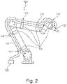
- eine schematische Schnittdarstellung eines Industrieroboterarmes mit fünf Befestigungshaltern und einem Wellschlauch,
- Figur 3
- eine schematische Schnittdarstellung eines Befestigungshalters mit einem starren Halter an einem Industrieroboterarm mit großem Durchmesser,
- Figur 4
- eine schematische Schnittdarstellung eines Befestigungshalters mit einem starren Halter an einem Industrieroboterarm mit mittlerem Durchmesser,
- Figur 5
- eine schematische Schnittdarstellung eines Befestigungshalters mit einem starren Halter an einem Industrieroboterarm mit kleinem Durchmesser, und
- Figur 6
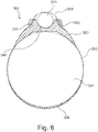
- eine schematische Schnittdarstellung eines Befestigungshalter mit einem PUR-Halter und einem Klettband zur gleichzeitigen Befestigung eines Wellrohres an den PUR-Halter und des PUR-Halters an einem Industrieroboterarm.
- Ein Befestigungshalter 101 weist ein Gurtband 105 und das Gurtband 105 an seinen beiden Enden einen Klettverschluss 109 auf. Des Weiteren umfasst der Befestigungshalter 101 einen PUR-Halter 103 und eine Stahlplatte 107. Das Gurtband 105 ist durch das Innere des PUR-Halters 103 geführt, wobei im Falle des durch den Klettverschluss 109 geschlossenen Gurtbandes 105 der PUR-Halter 103 eine Länge entsprechend eines Winkels 117 von 180° der Länge des geschlossenen Gurtbandes 105 sowie einen Winkel 117 von 180° eines Umfangs eines zu umschließenden Industrieroboterarmes 121 einnimmt.
- Die Stahlplatte 107 ist innerhalb eines Hohlraumes im Inneren des PUR-Halters 103 angeordnet. Die Stahlplatte 107 weist zwei Schraubgewinde auf, in welche zwei Schrauben 115 einer schwenkbaren Schelle 111 geschraubt sind. Hierbei sind die beiden Schrauben 115 durch zwei Öffnungen in dem PUR-Halter 103 in die Stahlplatte 107 geführt. Die schwenkbare Schelle 111 trägt in ihrem Inneren einen Wellschlauch 113. Der Wellschlauch weist eine Nennweite von DN 25 auf.
- Ein Industrieroboterarm 121 weist sechs Rotationsachsen auf. Am Ende des Industrieroboterarms 121 ist ein Montagewerkzeug 123 zur Montage von Werkstücken angeordnet. Das Montagewerkzeug 123 ist über den Wellschlauch 113 mit einer Zentralversorgung 125 verbunden. In dem Wellschlauch 113 sind eine Stromversorgungsleitung, eine Signalleitung und ein Druckluftschlauch von der Zentralversorgung 125 bis zum Werkzeug 123 geführt.
- An fünf Positionen entlang des Industrieroboterarmes 121 sind fünf Befestigungshalter 101 durch Festziehen des jeweiligen Gurtbandes 105 und Verschließen mittels des jeweiligen Klettverschlusses 109 positioniert und befestigt worden. Die Befestigungshalter 101 sind durch einen Reibschluss zwischen einer jeweils am Industrieroboterarm 121 anliegenden Fläche des jeweiligen PUR-Halters 103 und einer anliegenden Fläche des aus Aluminium bestehenden Industrieroboterarmes 121 lagefixiert.
- Der Wellschlauch 113 ist jeweils mittels schwenkbarer Schellen 111 an den fünf Befestigungshaltern 101 verbunden, sodass der Wellschlauch 113 eng entlang des Industrieroboterarmes 121 geführt ist.
- Aufgrund des elastischen PUR-Halters 103 jedes Befestigungshalters 101 ist der Wellschlauch 113 biegeflexibel entlang des Industrieroboterarmes 121 geführt und unterliegt aufgrund von Bewegungen des Industrieroboterarmes 121 während der Montage nur geringen Biegebelastungen. Durch die enge Führung des Wellschlauches 113 liegen keine Störkonturen durch die Befestigungshalter 101 im Arbeitsbereich des Industrieroboterarmes 121 vor. Somit erfolgt eine optimale Strom-, Signal- und Druckluftversorgung des Industrieroboterarmes 121 über den enggeführten Wellschlauch 113, ohne dass der Betrieb des Industrieroboterarmes 121 bei der Montage der Werkstücke beeinträchtigt wird.
- In einer Alternative weist ein Befestigungshalter 201 einen starren Halter 203 aus einem Acryl-Butadien-StyrolCopolymer auf. Des Weiteren umfasst der Befestigungshalter 201 ein Polyester-Band 205 mit einem Klemmverschluss 209.
- Der starre Halter 203 ist auf seiner innenliegenden Seite seiner beiden Schenkel eckig ausgeführt und weist an seiner Oberseite zwei Schraubgewinde 225 auf. Das Polyester-Band 205 ist durch den starren Halter 203 geführt.
- Zum Befestigen um einen Industrieroboterarm 221 wird das Polyester-Band 205 mit dem starren Halter 203 um den Industrieroboterarm 221 gespannt und mittels des Klettverschlusses 209 festgezogen und verschlossen.
- Der Industrieroboterarm 221 weist einen großen Durchmesser von 250mm auf, sodass der starre Halter 203 mit den beiden Enden seiner Schenkel auf einem oberen Abschnitt eines Umfangs des Industrieroboterarms 221 aufliegt, wobei ein Abstand zwischen den beiden Schenkeln einen 90° Winkel eines Umfanges des Industrieroboterarms 221 umfasst.
- Anschließend wird eine nicht gezeigte Klemmschelle mittels Schrauben in die Schraubgewinde 225 verschraubt und ein nicht gezeigter Versorgungsschlauch, welcher mehrere Daten- und Leistungskabel in seinem Inneren führt, in der Klemmschelle eingeklemmt.
- Nach Verwendung des Befestigungshalters 201 am Industrieroboterarm 221 wird der Befestigungshalter 201 mit dem starren Halter 203 in entsprechender Weise an einem Industrieroboterarm 231 befestigt. Der Industrieroboterarm 231 weist einen mittleren Durchmesser von 150mm auf, sodass der starre Halter 203 nicht mit den Enden seiner beiden Schenkel sondern an seinen innenliegenden Seiten auf dem Industrieroboterarm 231 aufliegt. Hierbei umfasst der starre Halter 203 einen Winkel von 135° eines Umfanges des Industrieroboterarms 231.
- In einer späteren Anwendung wird der Befestigungshalter 201 mit dem starren Halter 203 in analoger Weise an einem Industrieroboterarm 241 mit einem kleinen Durchmesser von 75mmm befestigt. Der starre Halter 203 liegt mittig an den innenliegenden Seiten seiner Schenkel auf dem Industrieroboterarm 241 auf und umfasst insgesamt einen Winkel 117 von 180° eines Umfanges des Industrieroboterarms 241.
- Somit ist der Befestigungshalter 201 mit dem starren Halter 203 flexible für unterschiedliche Industrieroboterarme nutzbar.
- In einer weiteren Alternative weist ein Befestigungshalter 301 einen flexiblen PUR-Halter 303, ein Klettband 305 mit einem Klettverschluss 309 und eine halbkreisförmige Aufnahme 340 auf. Der PUR-Halter 303 weist seitlich zwei Einführungsschlitze 330 auf, durch welche das Klettband 305 jeweils durch den oberen Teil des PUR-Halters 303 geführt ist. Entlang beider Schenkel des PUR-Halter 303 liegt das Klettband 305 jeweils außen zwischen einer Führung.
- Zur Montage wird das Klettband 305 durch die Einführungsschlitze 330 eingeführt und bildet dadurch einen Halbkreis über der halbkreisförmige Aufnahme 340 aus. Anschließend wird der Befestigungshalter 301 an einer vorgesehenen Stelle außen an einem Industrieroboterarm 321 positioniert. Ein Wellrohr 313 mit einem Außendurchmesser von 29,4 mm wird zwischen dem oberen Klettband 305 und dem PUR-Halter 303 durchgeführt und in die halbkreisförmige Aufnahme 340 des PUR-Halters 303 eingelegt. Das Klettband 305 wird um das Wellrohr 313 und den Industrieroboterarm 312 festgezogen und mittels des Klettverschlusses 309 verschlossen. Dadurch wird gleichzeitig in einem Arbeitsschritt das Wellrohr 313 am PUR-Halter 303 und der PUR-Halter 303 am Industrieroboterarm 321 befestigt. Durch eine unebene Ausführung des PUR-Halters 303 an einer innenliegenden Kontaktfläche zum Industrieroboterarm 321 ist der PUR-Halter 303 besser an einen Durchmesser des Industrieroboterarms 321 anpassbar und rutschhemmend.
- Somit wird ein Befestigungshalter 301 bereitgestellt, welcher frei von der Verwendung von Schrauben und Werkzeugen eine schnelle Installation ermöglicht und zudem eine sehr geringe Bauhöhe aufweist, welche nur geringfügig über einer Höhe des Wellrohres 313 liegt.
Claims (14)
- Befestigungsvorrichtung (101) für zumindest einen Versorgungsschlauch (113) und/oder zumindest eine Versorgungsleitung zum Befestigen an einem Industrieroboterarm (121) mit einem Halter (103), einer zuordenbaren Halteeinheit (111) für den Versorgungsschlauch (113) und/oder die Versorgungsleitung und einem verschließbaren Spannelement (105), wobei der Halter (103) am verschließbaren Spannelement (105) angeordnet ist, sodass der Halter (103) durch ein Umspannen und ein Verschließen des Spannelements (105) um den Industrieroboterarm (121) flexibel an dem Industrieroboterarm (121) befestigbar und/oder positionierbar ist und somit im Falle eines Verbindens des Halters (103) mit der zuordenbaren Halteeinheit (111) der Versorgungsschlauch (113) und/oder die Versorgungsleitung gezielt ausrichtbar ist oder sind, dadurch gekennzeichnet, dass das verschließbare Spannelement (105) durch ein Inneres des Halters (103) geführt ist.
- Befestigungsvorrichtung (101) nach Anspruch 1, dadurch gekennzeichnet, dass das verschließbare Spannelement (105) in einer Längsrichtung des Halters (103) geführt ist.
- Befestigungsvorrichtung (101) nach einem der Ansprüche 1 oder 2, dadurch gekennzeichnet, dass der Halter (103) ein elastisches Material aufweist, sodass im Falle des Umspannens und Verschließens des Spannelementes (105) um den Industrieroboterarm (121) durch einen Reibschluss zwischen dem elastischen Material des Halters (103) und einem Material des Industrieroboterarms (121) der Halter (103) lagefixiert ist.
- Befestigungsvorrichtung (101) nach Anspruch 3, dadurch gekennzeichnet, dass der Halter (103) Polyurethan, insbesondere mit einer Shore-Härte von 30° bis 60° Shore A, aufweist.
- Befestigungsvorrichtung (101) nach einem der Ansprüche 3 oder 4, dadurch gekennzeichnet, dass im Falle des Reibschlusses das elastische Material und/oder das Polyurethan des Halters (103) einen Winkelbereich von 90° bis 230°, bevorzugt 150° bis 180°, quer zu einer Längsrichtung des Industrieroboterarmes (121) umfasst.
- Befestigungsvorrichtung (101) nach einem der Ansprüche 3 bis 5, dadurch gekennzeichnet, dass der Halter (103) biegeflexibel ist, sodass der biegeflexible Halter an unterschiedliche Durchmesser des Industrieroboterarms (121) anpassbar ist.
- Befestigungsvorrichtung (101) nach einem der Ansprüche 1 bis 6, dadurch gekennzeichnet, dass der Halter (103) und/oder der biegeflexible Halter mindestens einen Einschnitt oder mehrere Einschnitte an einer Kontaktfläche zum Industrieroboterarm (121) aufweist, sodass der Halter (103) und/oder der biegeflexible Halter an den Industrieroboterarm (121) formbar ist.
- Befestigungsvorrichtung (101) nach einem der Ansprüche 1 bis 7, dadurch gekennzeichnet, dass der Halter (103) durch ein mechanisches und/oder chemisches Mittel an dem Industrieroboterarm (121) wechselseitig lagefixierbar ist.
- Befestigungsvorrichtung (101) nach einem der Ansprüche 1 bis 8, dadurch gekennzeichnet, dass das verschließbare Spannelement (105) einen Klett- (109), Schnapp-, Klemm-, Anpress-, Koppel- und/oder D-Ring-Verschluss aufweist.
- Befestigungsvorrichtung (101) nach einem der Ansprüche 1 bis 9, dadurch gekennzeichnet, dass die Befestigungsvorrichtung (101) eine Fixierplatte (107) mit mindestens einer Verbindungseinheit (115) zum Verbinden der Fixierplatte (107) mit der zuordenbaren Halteeinheit (111) aufweist und die Fixierplatte (107) am Halter (103) angeordnet ist.
- Befestigungsvorrichtung (101) nach Anspruch 10, dadurch gekennzeichnet, dass der Halter (103) eine Aufnahmeeinrichtung aufweist, an oder in welcher die Fixierplatte (107) an- oder einbringbar ist, sodass die Fixierplatte (107) austauschbar ist.
- Befestigungsvorrichtung (101) nach Anspruch 11, dadurch gekennzeichnet, dass die Fixierplatte (107) innerhalb des Halters (103) angeordnet ist, wobei die mindestens eine Verbindungseinheit (115) zum Verbinden mit der Halteeinheit (111) von außen zugängig ist.
- Befestigungsvorrichtung (101) nach einem der Ansprüche 1 bis 12, dadurch gekennzeichnet, dass die Befestigungsvorrichtung (101) und/oder die Befestigungsvorrichtungen die Halteeinheit (111) und/oder den Versorgungsschlauch (113) und/oder die Versorgungsleitung aufweist oder aufweisen, sodass der Versorgungsschlauch (113) und/oder die Versorgungsleitung entlang einer Außenkontur des Industrieroboterarms (121) führbar ist.
- Befestigungsvorrichtung (101) nach einem der Ansprüche 1 bis 13, dadurch gekennzeichnet, dass der Halter (103) ein rundes, ovales, eckiges und/oder rechteckiges Profil aufweist.
Applications Claiming Priority (2)
| Application Number | Priority Date | Filing Date | Title |
|---|---|---|---|
| DE102017107043.5A DE102017107043A1 (de) | 2017-03-31 | 2017-03-31 | Befestigungsvorrichtung für einen Versorgungsschlauch und/oder eine Versorgungsleitung zum Befestigen an einem Industrieroboterarm |
| PCT/DE2018/200015 WO2018177482A1 (de) | 2017-03-31 | 2018-02-23 | Befestigungsvorrichtung für einen versorgungsschlauch und/oder eine versorgungsleitung zum befestigen an einem industrieroboterarm |
Publications (2)
| Publication Number | Publication Date |
|---|---|
| EP3577380A1 EP3577380A1 (de) | 2019-12-11 |
| EP3577380B1 true EP3577380B1 (de) | 2022-10-26 |
Family
ID=61832234
Family Applications (1)
| Application Number | Title | Priority Date | Filing Date |
|---|---|---|---|
| EP18714434.0A Active EP3577380B1 (de) | 2017-03-31 | 2018-02-23 | Befestigungsvorrichtung für einen versorgungsschlauch und/oder eine versorgungsleitung zum befestigen an einem industrieroboterarm |
Country Status (6)
| Country | Link |
|---|---|
| US (1) | US11446830B2 (de) |
| EP (1) | EP3577380B1 (de) |
| KR (1) | KR102464741B1 (de) |
| CN (1) | CN110573780B (de) |
| DE (1) | DE102017107043A1 (de) |
| WO (1) | WO2018177482A1 (de) |
Families Citing this family (3)
| Publication number | Priority date | Publication date | Assignee | Title |
|---|---|---|---|---|
| DE202019101830U1 (de) | 2019-04-01 | 2019-04-29 | Igus Gmbh | Befestigungsteil |
| US11602862B2 (en) * | 2020-03-11 | 2023-03-14 | Energid Technologies Corporation | Pneumatic hose assembly for a robot |
| US12162738B2 (en) * | 2021-10-28 | 2024-12-10 | Toyota Research Institute, Inc. | Robots and sensor systems having compliant members |
Family Cites Families (46)
| Publication number | Priority date | Publication date | Assignee | Title |
|---|---|---|---|---|
| US811343A (en) * | 1905-07-07 | 1906-01-30 | Ward C Walker | Hose-clamp. |
| GB868590A (en) * | 1957-07-11 | 1961-05-17 | James Stewart | Improvements in or relating to adjustable clamps for pipes |
| US3235925A (en) * | 1964-01-23 | 1966-02-22 | Republic Ind Corp | Clamping bands |
| US3851979A (en) * | 1972-09-20 | 1974-12-03 | Woodhead Inc Daniel | Cable and hose clamp |
| DE3434899A1 (de) | 1983-10-19 | 1985-05-23 | Kuka Schweissanlagen + Roboter Gmbh, 8900 Augsburg | Vorrichtung zum aussenseitigen halten und fuehren von versorgungsleitungen zu bewegten werkzeugen von manipulatoren |
| DE8814906U1 (de) * | 1988-11-30 | 1989-01-26 | Reis GmbH & Co. Maschinenfabrik, 8753 Obernburg | Halterung für ein Schlauchpaket an einem Roboterarm |
| DE9103497U1 (de) * | 1991-03-21 | 1991-06-20 | Kuka Schweissanlagen + Roboter Gmbh, 8900 Augsburg | Mehrachsiger Manipulator |
| US5474268A (en) * | 1992-02-10 | 1995-12-12 | Yu; Michael | Agricultural and industrial tie |
| US5777267A (en) * | 1996-06-28 | 1998-07-07 | Abb Flexible Automation, Inc. | Harness assembly to provide signals to end effector |
| US5816736A (en) * | 1997-03-20 | 1998-10-06 | Flex-Cable, Inc. | Robot arm assembly |
| US5937488A (en) * | 1998-07-13 | 1999-08-17 | Tyton Hellerman Corporation | Brakeline to axle clamp |
| DE29902947U1 (de) * | 1999-02-19 | 1999-07-08 | Kuka Roboter GmbH, 86165 Augsburg | Roboterteil |
| GB9915844D0 (en) * | 1999-07-06 | 1999-09-08 | Lasalle Products & Services Di | Improvements in or relating to cable protectors |
| US6431018B1 (en) * | 1999-09-09 | 2002-08-13 | Fanuc Ltd. | Guide device for wiring member and/or piping member and robot with guide device |
| JP2001169443A (ja) * | 1999-12-02 | 2001-06-22 | Sumitomo Wiring Syst Ltd | 部材固定用クリップ |
| DE20109419U1 (de) * | 2001-06-06 | 2001-08-23 | LEONI Protec Cable Systems GmbH, 98574 Schmalkalden | Roboter mit einer eine Spannschelle aufweisenden Haltevorrichtung zum Positionieren eines Schlauches längs des Roboters und entsprechende Haltevorrichtung sowie Spannschelle |
| JP4142304B2 (ja) * | 2001-10-22 | 2008-09-03 | 株式会社安川電機 | アーク溶接用ロボット |
| DE10222732A1 (de) * | 2002-05-23 | 2003-12-18 | Rasmussen Gmbh | Schelle zum Festklemmen eines Schlauches auf einem Rohr mittels eines Federbandes, dessen Endabschnitte im aufgeweiteten Zustand verriegelbar sind, und Entriegelungsvorrichtung für die Schelle |
| US7854414B2 (en) * | 2004-04-20 | 2010-12-21 | Artificial Lift Company Limited | Cable clamps |
| US7306755B2 (en) * | 2005-02-28 | 2007-12-11 | Delphi Technologies, Inc. | Method of fabricating a strap with rotatably mounted clip |
| SE528956C2 (sv) * | 2005-09-06 | 2007-03-20 | Aba Sweden Ab | Fixering för slangklämma |
| JP4680700B2 (ja) * | 2005-07-07 | 2011-05-11 | 株式会社キャプテン インダストリーズ | ケーブル取付け装置 |
| KR100638637B1 (ko) | 2005-10-19 | 2006-10-27 | 기아자동차주식회사 | 와이어링 간격유지용 밴드케이블 |
| KR100811236B1 (ko) * | 2006-06-29 | 2008-03-10 | 최광술 | 산업용 로봇의 케이블 가이드장치 |
| JP2008023680A (ja) | 2006-07-24 | 2008-02-07 | Yutaka Electronics Industry Co Ltd | ロボットアーム用ブラケット及びロボットアーム |
| BRPI0604028B1 (pt) * | 2006-09-04 | 2019-12-24 | Embraco Ind De Compressores E Solucoes Em Refrigeracao Ltda | abraçadeira para conexões tubulares em pequenos sistemas de refrigeração |
| US7861982B1 (en) * | 2006-11-16 | 2011-01-04 | International Clamps, Inc. | Subsea clamp for hoses and control lines |
| US7520475B2 (en) * | 2007-01-18 | 2009-04-21 | Klo-Shure, Inc. | Pipe insulating coupling with integrated mounting clamp and closure mechanism |
| DE102007008985B4 (de) * | 2007-02-23 | 2016-09-08 | Kuka Roboter Gmbh | Haltevorrichtung für eine Energiezuführung |
| US7614593B2 (en) * | 2007-05-17 | 2009-11-10 | International Clamps, Inc. | Lined clamp for hoses and control lines |
| US7546985B1 (en) | 2007-12-10 | 2009-06-16 | Kwang Sul Choi | Cable guide device for industrial robot |
| US8998150B2 (en) * | 2010-01-29 | 2015-04-07 | The Subsea Company | Retrofit clamp for MUX, umbilicals and IWOCS |
| DE102010043121A1 (de) * | 2010-10-29 | 2012-05-03 | Siemens Aktiengesellschaft | Roboteranordnung mit einem Führungselement für Versorgungsleitungen |
| FR2990744B1 (fr) * | 2012-05-16 | 2014-06-13 | Airbus Operations Sas | Support pour le cheminement de conduits dans une aile d'aeronef |
| CN203348747U (zh) * | 2013-06-26 | 2013-12-18 | 江苏新丰电子有限公司 | 一种新型的带状夹紧装置 |
| US9512941B2 (en) * | 2013-07-23 | 2016-12-06 | Hawken Holdings, Llc | Conduit guide apparatus, system, and method |
| WO2015084616A1 (en) * | 2013-12-05 | 2015-06-11 | Erico International Corporation | Plumbing bracket assembly |
| CN203611261U (zh) * | 2013-12-10 | 2014-05-28 | 上海发那科机器人有限公司 | 一种工业机器人管线结构及包括该管线结构的机器人手臂 |
| US10107419B2 (en) * | 2014-03-31 | 2018-10-23 | Abey Australia Pty. Ltd. | Pipe clips and brackets therefor |
| BR112017001415A2 (pt) * | 2014-07-22 | 2017-11-21 | Ameriforge Group Inc | fechamentos de modo de falha múltipla e métodos relacionados |
| GB2537360B (en) * | 2015-04-10 | 2017-08-30 | Subsea 7 Norway As | Installing Heated Subsea Pipelines |
| CN204692753U (zh) * | 2015-06-17 | 2015-10-07 | 国网山东省电力公司潍坊供电公司 | 旁路电缆固定支架 |
| CN105370995B (zh) * | 2015-12-17 | 2017-07-04 | 安徽江淮汽车集团股份有限公司 | 一种管线固定扎带总成 |
| US10415609B2 (en) * | 2016-03-29 | 2019-09-17 | Bitzer Kuehlmaschinenbau Gmbh | Insulating sleeve |
| GB201610790D0 (en) * | 2016-06-21 | 2016-08-03 | Advanced Insulation Plc | Mounting arrangement |
| FR3059388B1 (fr) * | 2016-11-28 | 2018-11-16 | Financiere De Beaumont - Fdb | Dispositif concu pour fixer au moins un cable le long d'un conduit, et procede de mise en œuvre d'un tel dispositif |
-
2017
- 2017-03-31 DE DE102017107043.5A patent/DE102017107043A1/de not_active Ceased
-
2018
- 2018-02-23 EP EP18714434.0A patent/EP3577380B1/de active Active
- 2018-02-23 CN CN201880021189.9A patent/CN110573780B/zh active Active
- 2018-02-23 US US16/496,217 patent/US11446830B2/en active Active
- 2018-02-23 KR KR1020197031795A patent/KR102464741B1/ko active Active
- 2018-02-23 WO PCT/DE2018/200015 patent/WO2018177482A1/de not_active Ceased
Also Published As
| Publication number | Publication date |
|---|---|
| EP3577380A1 (de) | 2019-12-11 |
| US20200055201A1 (en) | 2020-02-20 |
| DE102017107043A1 (de) | 2018-10-04 |
| KR20190130007A (ko) | 2019-11-20 |
| US11446830B2 (en) | 2022-09-20 |
| WO2018177482A1 (de) | 2018-10-04 |
| CN110573780B (zh) | 2022-04-12 |
| KR102464741B1 (ko) | 2022-11-09 |
| CN110573780A (zh) | 2019-12-13 |
Similar Documents
| Publication | Publication Date | Title |
|---|---|---|
| DE102012100290B4 (de) | Gelenkige Schutz- und Führungsvorrichtung für Kabel und Schläuche | |
| DE69102841T2 (de) | Industrieroboter mit leitungsmechanismus. | |
| DE202017102147U1 (de) | Leitungsdurchführung, insbesondere Zugentlastung für eine Energieführungskette | |
| EP3577380A1 (de) | Befestigungsvorrichtung für einen versorgungsschlauch und/oder eine versorgungsleitung zum befestigen an einem industrieroboterarm | |
| DE102007018543A1 (de) | Vorrichtung zum Führen von Versorgungsleitungen entlang der Struktur eines Industrieroboters | |
| DE202012011535U1 (de) | Haltevorrichtung für wenigstens eine Leitung in einem Manipulatorarm und Manipulatorarm mit einer solchen Haltevorrichtung | |
| EP1029638B1 (de) | Roboterteil mit einem Schlauchhalter | |
| DE2341814C3 (de) | Befestigungsvorrichtung | |
| DE202020005932U1 (de) | Haltevorrichtung für eine Energiezuführungsleitung | |
| EP3967888A1 (de) | Befestigungsvorrichtung | |
| DE102019125942A1 (de) | Sensorhalterung und Robotersystem | |
| EP2357060B1 (de) | Aufnahmevorrichtung für Werkstückaufnahmen | |
| DE202009001797U1 (de) | Werkzeughalterung für Elektrohandwerkzeuggeräte | |
| DE102010007581B4 (de) | Energieführungskette | |
| DE202016100617U1 (de) | Halterung für Anzeige- oder Bediengeräte | |
| DE4318145C2 (de) | Vorrichtung zur automatischen Montage von Schlauchsicherungselementen, insbesondere von Schneckengewindeschellen | |
| DE102017213860B4 (de) | Vorrichtung zum Entfernen von Deformationen aus Oberflächen | |
| DE3920690A1 (de) | Saeulenzieheinrichtung fuer spritzgiessmaschinen | |
| EP2523179A2 (de) | Schilderhalter | |
| DE202009000658U1 (de) | Spannelement zum Verspannen von Schlingen | |
| DE102022115060A1 (de) | Zuführeinrichtung | |
| DE202023101346U1 (de) | Spann- oder Greifvorrichtung | |
| DE10345838B4 (de) | Klemmvorrichtung für Kabel oder dergleichen | |
| DE20113962U1 (de) | Vorrichtung zum Halten eines Leitungsbündels bei einem Roboter | |
| DE2818812C2 (de) | Einrichtung zur Befestigung von Ventilgehäusen |
Legal Events
| Date | Code | Title | Description |
|---|---|---|---|
| STAA | Information on the status of an ep patent application or granted ep patent |
Free format text: STATUS: UNKNOWN |
|
| STAA | Information on the status of an ep patent application or granted ep patent |
Free format text: STATUS: THE INTERNATIONAL PUBLICATION HAS BEEN MADE |
|
| PUAI | Public reference made under article 153(3) epc to a published international application that has entered the european phase |
Free format text: ORIGINAL CODE: 0009012 |
|
| STAA | Information on the status of an ep patent application or granted ep patent |
Free format text: STATUS: REQUEST FOR EXAMINATION WAS MADE |
|
| 17P | Request for examination filed |
Effective date: 20190903 |
|
| AK | Designated contracting states |
Kind code of ref document: A1 Designated state(s): AL AT BE BG CH CY CZ DE DK EE ES FI FR GB GR HR HU IE IS IT LI LT LU LV MC MK MT NL NO PL PT RO RS SE SI SK SM TR |
|
| AX | Request for extension of the european patent |
Extension state: BA ME |
|
| DAV | Request for validation of the european patent (deleted) | ||
| DAX | Request for extension of the european patent (deleted) | ||
| RAP1 | Party data changed (applicant data changed or rights of an application transferred) |
Owner name: LEONI KABEL GMBH |
|
| STAA | Information on the status of an ep patent application or granted ep patent |
Free format text: STATUS: EXAMINATION IS IN PROGRESS |
|
| 17Q | First examination report despatched |
Effective date: 20210517 |
|
| GRAP | Despatch of communication of intention to grant a patent |
Free format text: ORIGINAL CODE: EPIDOSNIGR1 |
|
| STAA | Information on the status of an ep patent application or granted ep patent |
Free format text: STATUS: GRANT OF PATENT IS INTENDED |
|
| INTG | Intention to grant announced |
Effective date: 20220613 |
|
| GRAS | Grant fee paid |
Free format text: ORIGINAL CODE: EPIDOSNIGR3 |
|
| RAP1 | Party data changed (applicant data changed or rights of an application transferred) |
Owner name: BIZLINK INDUSTRY GERMANY GMBH |
|
| GRAA | (expected) grant |
Free format text: ORIGINAL CODE: 0009210 |
|
| STAA | Information on the status of an ep patent application or granted ep patent |
Free format text: STATUS: THE PATENT HAS BEEN GRANTED |
|
| AK | Designated contracting states |
Kind code of ref document: B1 Designated state(s): AL AT BE BG CH CY CZ DE DK EE ES FI FR GB GR HR HU IE IS IT LI LT LU LV MC MK MT NL NO PL PT RO RS SE SI SK SM TR |
|
| REG | Reference to a national code |
Ref country code: GB Ref legal event code: FG4D Free format text: NOT ENGLISH |
|
| REG | Reference to a national code |
Ref country code: CH Ref legal event code: EP |
|
| REG | Reference to a national code |
Ref country code: AT Ref legal event code: REF Ref document number: 1527254 Country of ref document: AT Kind code of ref document: T Effective date: 20221115 |
|
| RAP4 | Party data changed (patent owner data changed or rights of a patent transferred) |
Owner name: BIZLINK INDUSTRY GERMANY GMBH |
|
| REG | Reference to a national code |
Ref country code: DE Ref legal event code: R096 Ref document number: 502018010915 Country of ref document: DE |
|
| REG | Reference to a national code |
Ref country code: IE Ref legal event code: FG4D Free format text: LANGUAGE OF EP DOCUMENT: GERMAN |
|
| REG | Reference to a national code |
Ref country code: LT Ref legal event code: MG9D |
|
| REG | Reference to a national code |
Ref country code: NL Ref legal event code: MP Effective date: 20221026 |
|
| PG25 | Lapsed in a contracting state [announced via postgrant information from national office to epo] |
Ref country code: NL Free format text: LAPSE BECAUSE OF FAILURE TO SUBMIT A TRANSLATION OF THE DESCRIPTION OR TO PAY THE FEE WITHIN THE PRESCRIBED TIME-LIMIT Effective date: 20221026 |
|
| PG25 | Lapsed in a contracting state [announced via postgrant information from national office to epo] |
Ref country code: SE Free format text: LAPSE BECAUSE OF FAILURE TO SUBMIT A TRANSLATION OF THE DESCRIPTION OR TO PAY THE FEE WITHIN THE PRESCRIBED TIME-LIMIT Effective date: 20221026 Ref country code: PT Free format text: LAPSE BECAUSE OF FAILURE TO SUBMIT A TRANSLATION OF THE DESCRIPTION OR TO PAY THE FEE WITHIN THE PRESCRIBED TIME-LIMIT Effective date: 20230227 Ref country code: NO Free format text: LAPSE BECAUSE OF FAILURE TO SUBMIT A TRANSLATION OF THE DESCRIPTION OR TO PAY THE FEE WITHIN THE PRESCRIBED TIME-LIMIT Effective date: 20230126 Ref country code: LT Free format text: LAPSE BECAUSE OF FAILURE TO SUBMIT A TRANSLATION OF THE DESCRIPTION OR TO PAY THE FEE WITHIN THE PRESCRIBED TIME-LIMIT Effective date: 20221026 Ref country code: FI Free format text: LAPSE BECAUSE OF FAILURE TO SUBMIT A TRANSLATION OF THE DESCRIPTION OR TO PAY THE FEE WITHIN THE PRESCRIBED TIME-LIMIT Effective date: 20221026 Ref country code: ES Free format text: LAPSE BECAUSE OF FAILURE TO SUBMIT A TRANSLATION OF THE DESCRIPTION OR TO PAY THE FEE WITHIN THE PRESCRIBED TIME-LIMIT Effective date: 20221026 |
|
| PG25 | Lapsed in a contracting state [announced via postgrant information from national office to epo] |
Ref country code: RS Free format text: LAPSE BECAUSE OF FAILURE TO SUBMIT A TRANSLATION OF THE DESCRIPTION OR TO PAY THE FEE WITHIN THE PRESCRIBED TIME-LIMIT Effective date: 20221026 Ref country code: PL Free format text: LAPSE BECAUSE OF FAILURE TO SUBMIT A TRANSLATION OF THE DESCRIPTION OR TO PAY THE FEE WITHIN THE PRESCRIBED TIME-LIMIT Effective date: 20221026 Ref country code: LV Free format text: LAPSE BECAUSE OF FAILURE TO SUBMIT A TRANSLATION OF THE DESCRIPTION OR TO PAY THE FEE WITHIN THE PRESCRIBED TIME-LIMIT Effective date: 20221026 Ref country code: IS Free format text: LAPSE BECAUSE OF FAILURE TO SUBMIT A TRANSLATION OF THE DESCRIPTION OR TO PAY THE FEE WITHIN THE PRESCRIBED TIME-LIMIT Effective date: 20230226 Ref country code: HR Free format text: LAPSE BECAUSE OF FAILURE TO SUBMIT A TRANSLATION OF THE DESCRIPTION OR TO PAY THE FEE WITHIN THE PRESCRIBED TIME-LIMIT Effective date: 20221026 Ref country code: GR Free format text: LAPSE BECAUSE OF FAILURE TO SUBMIT A TRANSLATION OF THE DESCRIPTION OR TO PAY THE FEE WITHIN THE PRESCRIBED TIME-LIMIT Effective date: 20230127 |
|
| P01 | Opt-out of the competence of the unified patent court (upc) registered |
Effective date: 20230530 |
|
| REG | Reference to a national code |
Ref country code: DE Ref legal event code: R097 Ref document number: 502018010915 Country of ref document: DE |
|
| PG25 | Lapsed in a contracting state [announced via postgrant information from national office to epo] |
Ref country code: SM Free format text: LAPSE BECAUSE OF FAILURE TO SUBMIT A TRANSLATION OF THE DESCRIPTION OR TO PAY THE FEE WITHIN THE PRESCRIBED TIME-LIMIT Effective date: 20221026 Ref country code: RO Free format text: LAPSE BECAUSE OF FAILURE TO SUBMIT A TRANSLATION OF THE DESCRIPTION OR TO PAY THE FEE WITHIN THE PRESCRIBED TIME-LIMIT Effective date: 20221026 Ref country code: EE Free format text: LAPSE BECAUSE OF FAILURE TO SUBMIT A TRANSLATION OF THE DESCRIPTION OR TO PAY THE FEE WITHIN THE PRESCRIBED TIME-LIMIT Effective date: 20221026 Ref country code: DK Free format text: LAPSE BECAUSE OF FAILURE TO SUBMIT A TRANSLATION OF THE DESCRIPTION OR TO PAY THE FEE WITHIN THE PRESCRIBED TIME-LIMIT Effective date: 20221026 Ref country code: CZ Free format text: LAPSE BECAUSE OF FAILURE TO SUBMIT A TRANSLATION OF THE DESCRIPTION OR TO PAY THE FEE WITHIN THE PRESCRIBED TIME-LIMIT Effective date: 20221026 |
|
| PG25 | Lapsed in a contracting state [announced via postgrant information from national office to epo] |
Ref country code: SK Free format text: LAPSE BECAUSE OF FAILURE TO SUBMIT A TRANSLATION OF THE DESCRIPTION OR TO PAY THE FEE WITHIN THE PRESCRIBED TIME-LIMIT Effective date: 20221026 Ref country code: AL Free format text: LAPSE BECAUSE OF FAILURE TO SUBMIT A TRANSLATION OF THE DESCRIPTION OR TO PAY THE FEE WITHIN THE PRESCRIBED TIME-LIMIT Effective date: 20221026 |
|
| PLBE | No opposition filed within time limit |
Free format text: ORIGINAL CODE: 0009261 |
|
| STAA | Information on the status of an ep patent application or granted ep patent |
Free format text: STATUS: NO OPPOSITION FILED WITHIN TIME LIMIT |
|
| PG25 | Lapsed in a contracting state [announced via postgrant information from national office to epo] |
Ref country code: MC Free format text: LAPSE BECAUSE OF FAILURE TO SUBMIT A TRANSLATION OF THE DESCRIPTION OR TO PAY THE FEE WITHIN THE PRESCRIBED TIME-LIMIT Effective date: 20221026 |
|
| REG | Reference to a national code |
Ref country code: CH Ref legal event code: PL |
|
| 26N | No opposition filed |
Effective date: 20230727 |
|
| REG | Reference to a national code |
Ref country code: BE Ref legal event code: MM Effective date: 20230228 |
|
| GBPC | Gb: european patent ceased through non-payment of renewal fee |
Effective date: 20230223 |
|
| PG25 | Lapsed in a contracting state [announced via postgrant information from national office to epo] |
Ref country code: LU Free format text: LAPSE BECAUSE OF NON-PAYMENT OF DUE FEES Effective date: 20230223 Ref country code: LI Free format text: LAPSE BECAUSE OF NON-PAYMENT OF DUE FEES Effective date: 20230228 Ref country code: CH Free format text: LAPSE BECAUSE OF NON-PAYMENT OF DUE FEES Effective date: 20230228 |
|
| PG25 | Lapsed in a contracting state [announced via postgrant information from national office to epo] |
Ref country code: SI Free format text: LAPSE BECAUSE OF FAILURE TO SUBMIT A TRANSLATION OF THE DESCRIPTION OR TO PAY THE FEE WITHIN THE PRESCRIBED TIME-LIMIT Effective date: 20221026 |
|
| REG | Reference to a national code |
Ref country code: IE Ref legal event code: MM4A |
|
| PG25 | Lapsed in a contracting state [announced via postgrant information from national office to epo] |
Ref country code: GB Free format text: LAPSE BECAUSE OF NON-PAYMENT OF DUE FEES Effective date: 20230223 |
|
| PG25 | Lapsed in a contracting state [announced via postgrant information from national office to epo] |
Ref country code: IE Free format text: LAPSE BECAUSE OF NON-PAYMENT OF DUE FEES Effective date: 20230223 Ref country code: GB Free format text: LAPSE BECAUSE OF NON-PAYMENT OF DUE FEES Effective date: 20230223 |
|
| PG25 | Lapsed in a contracting state [announced via postgrant information from national office to epo] |
Ref country code: BE Free format text: LAPSE BECAUSE OF NON-PAYMENT OF DUE FEES Effective date: 20230228 |
|
| REG | Reference to a national code |
Ref country code: AT Ref legal event code: MM01 Ref document number: 1527254 Country of ref document: AT Kind code of ref document: T Effective date: 20230223 |
|
| PG25 | Lapsed in a contracting state [announced via postgrant information from national office to epo] |
Ref country code: AT Free format text: LAPSE BECAUSE OF NON-PAYMENT OF DUE FEES Effective date: 20230223 |
|
| PG25 | Lapsed in a contracting state [announced via postgrant information from national office to epo] |
Ref country code: AT Free format text: LAPSE BECAUSE OF NON-PAYMENT OF DUE FEES Effective date: 20230223 |
|
| PG25 | Lapsed in a contracting state [announced via postgrant information from national office to epo] |
Ref country code: IT Free format text: LAPSE BECAUSE OF FAILURE TO SUBMIT A TRANSLATION OF THE DESCRIPTION OR TO PAY THE FEE WITHIN THE PRESCRIBED TIME-LIMIT Effective date: 20221026 |
|
| PG25 | Lapsed in a contracting state [announced via postgrant information from national office to epo] |
Ref country code: BG Free format text: LAPSE BECAUSE OF FAILURE TO SUBMIT A TRANSLATION OF THE DESCRIPTION OR TO PAY THE FEE WITHIN THE PRESCRIBED TIME-LIMIT Effective date: 20221026 |
|
| PG25 | Lapsed in a contracting state [announced via postgrant information from national office to epo] |
Ref country code: BG Free format text: LAPSE BECAUSE OF FAILURE TO SUBMIT A TRANSLATION OF THE DESCRIPTION OR TO PAY THE FEE WITHIN THE PRESCRIBED TIME-LIMIT Effective date: 20221026 |
|
| PG25 | Lapsed in a contracting state [announced via postgrant information from national office to epo] |
Ref country code: CY Free format text: LAPSE BECAUSE OF FAILURE TO SUBMIT A TRANSLATION OF THE DESCRIPTION OR TO PAY THE FEE WITHIN THE PRESCRIBED TIME-LIMIT; INVALID AB INITIO Effective date: 20180223 |
|
| PG25 | Lapsed in a contracting state [announced via postgrant information from national office to epo] |
Ref country code: HU Free format text: LAPSE BECAUSE OF FAILURE TO SUBMIT A TRANSLATION OF THE DESCRIPTION OR TO PAY THE FEE WITHIN THE PRESCRIBED TIME-LIMIT; INVALID AB INITIO Effective date: 20180223 |
|
| PG25 | Lapsed in a contracting state [announced via postgrant information from national office to epo] |
Ref country code: TR Free format text: LAPSE BECAUSE OF FAILURE TO SUBMIT A TRANSLATION OF THE DESCRIPTION OR TO PAY THE FEE WITHIN THE PRESCRIBED TIME-LIMIT Effective date: 20221026 |
|
| PGFP | Annual fee paid to national office [announced via postgrant information from national office to epo] |
Ref country code: DE Payment date: 20260217 Year of fee payment: 9 |
|
| PGFP | Annual fee paid to national office [announced via postgrant information from national office to epo] |
Ref country code: FR Payment date: 20260219 Year of fee payment: 9 |