EP3576509A1 - Heat sink - Google Patents
Heat sink Download PDFInfo
- Publication number
- EP3576509A1 EP3576509A1 EP17894434.4A EP17894434A EP3576509A1 EP 3576509 A1 EP3576509 A1 EP 3576509A1 EP 17894434 A EP17894434 A EP 17894434A EP 3576509 A1 EP3576509 A1 EP 3576509A1
- Authority
- EP
- European Patent Office
- Prior art keywords
- heat radiating
- radiating fin
- heat
- fins
- heat sink
- Prior art date
- Legal status (The legal status is an assumption and is not a legal conclusion. Google has not performed a legal analysis and makes no representation as to the accuracy of the status listed.)
- Granted
Links
Images


Classifications
-
- F—MECHANICAL ENGINEERING; LIGHTING; HEATING; WEAPONS; BLASTING
- F28—HEAT EXCHANGE IN GENERAL
- F28D—HEAT-EXCHANGE APPARATUS, NOT PROVIDED FOR IN ANOTHER SUBCLASS, IN WHICH THE HEAT-EXCHANGE MEDIA DO NOT COME INTO DIRECT CONTACT
- F28D15/00—Heat-exchange apparatus with the intermediate heat-transfer medium in closed tubes passing into or through the conduit walls ; Heat-exchange apparatus employing intermediate heat-transfer medium or bodies
-
- F—MECHANICAL ENGINEERING; LIGHTING; HEATING; WEAPONS; BLASTING
- F28—HEAT EXCHANGE IN GENERAL
- F28F—DETAILS OF HEAT-EXCHANGE AND HEAT-TRANSFER APPARATUS, OF GENERAL APPLICATION
- F28F13/00—Arrangements for modifying heat-transfer, e.g. increasing, decreasing
- F28F13/06—Arrangements for modifying heat-transfer, e.g. increasing, decreasing by affecting the pattern of flow of the heat-exchange media
- F28F13/08—Arrangements for modifying heat-transfer, e.g. increasing, decreasing by affecting the pattern of flow of the heat-exchange media by varying the cross-section of the flow channels
-
- F—MECHANICAL ENGINEERING; LIGHTING; HEATING; WEAPONS; BLASTING
- F28—HEAT EXCHANGE IN GENERAL
- F28F—DETAILS OF HEAT-EXCHANGE AND HEAT-TRANSFER APPARATUS, OF GENERAL APPLICATION
- F28F3/00—Plate-like or laminated elements; Assemblies of plate-like or laminated elements
- F28F3/02—Elements or assemblies thereof with means for increasing heat-transfer area, e.g. with fins, with recesses, with corrugations
-
- F—MECHANICAL ENGINEERING; LIGHTING; HEATING; WEAPONS; BLASTING
- F28—HEAT EXCHANGE IN GENERAL
- F28F—DETAILS OF HEAT-EXCHANGE AND HEAT-TRANSFER APPARATUS, OF GENERAL APPLICATION
- F28F3/00—Plate-like or laminated elements; Assemblies of plate-like or laminated elements
- F28F3/12—Elements constructed in the shape of a hollow panel, e.g. with channels
-
- H—ELECTRICITY
- H05—ELECTRIC TECHNIQUES NOT OTHERWISE PROVIDED FOR
- H05K—PRINTED CIRCUITS; CASINGS OR CONSTRUCTIONAL DETAILS OF ELECTRIC APPARATUS; MANUFACTURE OF ASSEMBLAGES OF ELECTRICAL COMPONENTS
- H05K7/00—Constructional details common to different types of electric apparatus
- H05K7/20—Modifications to facilitate cooling, ventilating, or heating
- H05K7/2039—Modifications to facilitate cooling, ventilating, or heating characterised by the heat transfer by conduction from the heat generating element to a dissipating body
- H05K7/20409—Outer radiating structures on heat dissipating housings, e.g. fins integrated with the housing
-
- H—ELECTRICITY
- H10—SEMICONDUCTOR DEVICES; ELECTRIC SOLID-STATE DEVICES NOT OTHERWISE PROVIDED FOR
- H10W—GENERIC PACKAGES, INTERCONNECTIONS, CONNECTORS OR OTHER CONSTRUCTIONAL DETAILS OF DEVICES COVERED BY CLASS H10
- H10W40/00—Arrangements for thermal protection or thermal control
- H10W40/20—Arrangements for cooling
- H10W40/22—Arrangements for cooling characterised by their shape, e.g. having conical or cylindrical projections
- H10W40/226—Arrangements for cooling characterised by their shape, e.g. having conical or cylindrical projections characterised by projecting parts, e.g. fins to increase surface area
-
- H—ELECTRICITY
- H10—SEMICONDUCTOR DEVICES; ELECTRIC SOLID-STATE DEVICES NOT OTHERWISE PROVIDED FOR
- H10W—GENERIC PACKAGES, INTERCONNECTIONS, CONNECTORS OR OTHER CONSTRUCTIONAL DETAILS OF DEVICES COVERED BY CLASS H10
- H10W40/00—Arrangements for thermal protection or thermal control
- H10W40/40—Arrangements for thermal protection or thermal control involving heat exchange by flowing fluids
- H10W40/47—Arrangements for thermal protection or thermal control involving heat exchange by flowing fluids by flowing liquids, e.g. forced water cooling
-
- F—MECHANICAL ENGINEERING; LIGHTING; HEATING; WEAPONS; BLASTING
- F28—HEAT EXCHANGE IN GENERAL
- F28F—DETAILS OF HEAT-EXCHANGE AND HEAT-TRANSFER APPARATUS, OF GENERAL APPLICATION
- F28F2215/00—Fins
-
- F—MECHANICAL ENGINEERING; LIGHTING; HEATING; WEAPONS; BLASTING
- F28—HEAT EXCHANGE IN GENERAL
- F28F—DETAILS OF HEAT-EXCHANGE AND HEAT-TRANSFER APPARATUS, OF GENERAL APPLICATION
- F28F2215/00—Fins
- F28F2215/04—Assemblies of fins having different features, e.g. with different fin densities
-
- H—ELECTRICITY
- H10—SEMICONDUCTOR DEVICES; ELECTRIC SOLID-STATE DEVICES NOT OTHERWISE PROVIDED FOR
- H10W—GENERIC PACKAGES, INTERCONNECTIONS, CONNECTORS OR OTHER CONSTRUCTIONAL DETAILS OF DEVICES COVERED BY CLASS H10
- H10W40/00—Arrangements for thermal protection or thermal control
- H10W40/20—Arrangements for cooling
- H10W40/22—Arrangements for cooling characterised by their shape, e.g. having conical or cylindrical projections
- H10W40/226—Arrangements for cooling characterised by their shape, e.g. having conical or cylindrical projections characterised by projecting parts, e.g. fins to increase surface area
- H10W40/228—Arrangements for cooling characterised by their shape, e.g. having conical or cylindrical projections characterised by projecting parts, e.g. fins to increase surface area the projecting parts being wire-shaped or pin-shaped
Definitions
- the present application relates to a heat sink which cools, for example, heat generating elements.
- SiC silicon carbide
- a component low in heat generation density, together with SiC high in heat generation density, is disposed on the identical heat sink.
- Japanese Patent No. 5605438 proposes a method whereby pin fins different in diameter are disposed, thus decreasing the fluid resistance of a region through which to cause refrigerant to flow at a large flow rate, and increasing the fluid resistance of a region through which to cause refrigerant to flow at a small flow rate.
- the heretofore mentioned method disclosed in PTL 1 is such that pin fins existing in the flow path of a cooler are changed in diameter and disposed, thereby adjusting the sectional area of the flow path, and changing the fluid resistances of local regions, thus adjusting the flow rate.
- a heretofore described kind of heretofore known method there is a problem in that it is not possible to make an extreme difference in flow rate, such as by making a difference of more than twice in flow rate per sectional area, on the identical heat sink.
- the present application has been made to solve the above problems and an object of the present application is to obtain a heat sink wherein it is possible, by providing a region small in flow rate and a region large in flow rate on the identical heat sink, to suppress an increase in pressure loss while increasing the cooling performance for a component high in heat generation density and decreasing the cooling performance for a component low in heat generation density.
- the heat sink disclosed in the present application is a heat sink having provided on a base thereof a plurality of heat radiating fins, the heat radiating fins being configured including a pin-shaped first heat radiating fin and a second heat radiating fin of a shape in which a plurality of columns of grooves which each meander at a narrow pitch are arranged side by side, wherein the first and second heat radiating fins are disposed, on an identical flat surface of the base, in parallel to a direction of flow of refrigerant.
- the heat sink disclosed in the present application as the refrigerant, which has flowed into the second heat radiating fin of the shape in which the plurality of columns of grooves which each meander at the narrow pitch are arranged side by side, repeatedly hits against the wall of each groove and changes the direction of flow, the fluid resistance is very high, and an inflow rate of refrigerant per sectional area is small.
- the fluid resistance of the pin-shaped first heat radiating fin is low, the inflow rate of refrigerant per sectional area of the first heat radiating fin is large.
- the first and second heat radiating fins are disposed in parallel to the flow of refrigerant, and thereby it is possible to suppress the total pressure loss.
- Fig. 1 is an exploded perspective view showing a heat sink according to a first embodiment of the invention
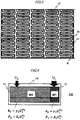
- Fig. 2 is a plan view of a base as seen from a surface on which fins are disposed.
- a heat sink 100 is configured including a base 14, which has a surface 10 having installed thereon a heat generating element low in heat generation density, a surface 11 having installed thereon a heat generating element high in heat generation density, a first heat radiating fin 12 which is provided on the rear of the surface 10 having installed thereon the heat generating element low in heat generation density and which is of a shape in which a plurality of columns of grooves which each meander in zigzag at a narrow pitch are arranged side by side, and a pin-shaped second heat radiating fin 13 provided on the rear of the surface 11 having installed thereon the heat generating element high in heat generation density; a jacket 15 in which the base 14 is stored; and a refrigerant inlet portion 16 and a refrigerant outlet portion 17 which are both provided on one of a pair of opposing lateral faces of the jacket 15.
- refrigerant passes through the refrigerant inlet portion 16 and enters a space between the jacket 15 and the base 14, as shown by arrow A of Fig. 1 .
- the refrigerant exchanges heat with the first and second heat radiating fins 12 and 13 which have received the heat from the heat generating elements, and the heat generating elements are cooled through the first and second heat radiating fins 12 and 13.
- the refrigerant which has received the heat through the heat exchange with the first and second heat radiating fins 12 and 13 is directly discharged outside the heat sink 100 through the refrigerant outlet portion 17.
- Any kind of refrigerant can be used irrespective of whether it is a liquid, a gas, or a gas-liquid mixture.
- Fig. 3 is an enlarged view of the first heat radiating fin 12 of the shape in which the plurality of columns of grooves which each meander in zigzag at the narrow pitch are arranged side by side.
- refrigerant having flowed into the first heat radiating fin 12 flows into a short flow path 18 parallel to the direction of circulation of the refrigerant, as shown by arrow B.
- the refrigerant hits against the wall of the flow path, makes a 90-degree turn in the direction of flow, and flows into a long flow path 19 perpendicular to the direction of circulation of the refrigerant.
- the refrigerant while hitting against the wall and making a 90-degree turn in the direction of flow, passes alternately through the short and long flow paths 18 and 19, and is discharged from the first heat radiating fin 12.
- the refrigerant flows while repeating a hit against the wall of the flow path and a 90-degree turn in the direction of flow, thus resulting in an immense increase in fluid resistance.
- refrigerant passing through the pin-shaped second heat radiating fin 13 which is disposed, in parallel to the flow of the refrigerant, adjacent to the first heat radiating fin 12 of the shape in which the plurality of columns of grooves which each meander in zigzag at the narrow pitch are arranged side by side does not changes sharply in the direction of flow compared with that when passing through the first heat radiating fin 12, and the flow path sectional area per sectional area in the direction of circulation of the refrigerant is large, so that the fluid resistance is low.
- the first heat radiating fin 12 in which the plurality of columns of cranked meandering grooves which make a 90-degree turn in the direction of flow of the refrigerant are arranged side by side, but the first heat radiating fin 12 may be of, for example, a shape in which a plurality of columns of V-shaped meandering grooves are arranged side by side.
- the second heat radiating fin 13 is larger in the refrigerant flow rate per sectional area in the direction of circulation of the refrigerant. Accordingly, the refrigerant flow rate immediately below the surface 11 having installed thereon the heat generating element high in heat generation density is large, and the heat sink 100 provides the heat generating element high in heat generation density with high cooling performance, and provides the heat generating element low in heat generation density with low cooling performance, enabling more conservation of energy for causing the refrigerant to circulate than when causing a large flow rate of refrigerant to flow uniformly throughout the whole heat sink.
- FIG. 4 is a schematic diagram of a base as seen from a surface having disposed thereon heat radiating fins of a heat sink 200 according to the second embodiment.
- the second heat radiating fin 13 low in fluid resistance increases in fluid resistance due to its decrease in sectional area, and so there is a case in which there arises a problem in that a reverse in refrigerant flow rate occurs, i.e., the first heat radiating fin 12 high in fluid resistance becomes larger in refrigerant flow rate than the second radiating fin 13 low in fluid resistance, causing a deficiency in the cooling performance for the heat generating element high in heat generation density.
- the problem is apt to occur, for example, in the case where the width W1 is extremely narrower than the width W2 for layout reasons.
- the cooling performance and pressure loss characteristics of the heat radiating fins are appropriately adjusted by the method shown as follows.
- h ⁇ 1 ⁇ U 1 ⁇ m 1
- P 1 ⁇ 1 ⁇ U 1 ⁇ n 1
- h 2 ⁇ 2 ⁇ U 2 ⁇ m 2
- P 2 ⁇ 2 ⁇ U 2 ⁇ n 2
- the characteristics of the first and second heat radiating fins 12 and 13 are set so as to satisfy the expression (8), and thereby it is possible to reliably make the second heat radiating fin 13 higher in cooling performance than the first heat radiating fin 12.
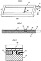
- FIG. 5 is a perspective view of a jacket of a heat sink 300 according to the third embodiment
- Fig. 6 shows a sectional view along the arrowed line A-A of Fig. 5
- Fig. 7 shows an enlarged view of the B portion of Fig. 6 .
- the first heat radiating fin 12 of the shape in which the plurality of columns of grooves which each meander in zigzag at the narrow pitch are arranged side by side, and the pin-shaped second heat radiating fin 13, by, for example, die casting or forging, it is better, from the viewpoint of an improvement in die releasability and die life, to provide a clearance between the first and second heat radiating fins 12 and 13.
- a projection-like wall 50 is provided in such a position on the jacket 15 as to fill the clearance between the first and second heat radiating fins 12 and 13 when the jacket 15 and the base 14 are put together, and furthermore, the clearance between the wall 50 and the first heat radiating fin 12 and the clearance between the wall 50 and the second heat radiating fin 13 are made smaller than a smaller one of the clearance between the adjacent fins of the first heat radiating fin 12 and the clearance between the adjacent fins of the second heat radiating fin 13, thereby increasing the fluid resistance of the clearance between the wall 50 and the first heat radiating fin 12 or between the wall 50 and the second heat radiating fin 13, thus preventing the refrigerant from flowing through the clearance, enabling suppression of a deterioration in cooling performance.
- Fig. 8 is a plan view of a base as seen from a surface having disposed thereon heat radiating fins of the heat sink according to the fourth embodiment
- Fig. 9 is an enlarged view of the C portion of Fig. 8 .
- protrusions 90 of a form in which some fins of the second heat radiating fin 13 are embedded in the first heat radiating fin 12 side end portion are provided to prevent refrigerant from flowing into the clearance between the first and second heat radiating fins 12 and 13 at a large flow rate.
- the heat sink 400 according to the fourth embodiment is such that by providing the protrusions 90, the clearance between the protrusions 90 and the adjacent fins of the second heat radiating fin 13 becomes substantially equal in fluid resistance to the second heat radiating fin 13 itself, thus preventing refrigerant from flowing into the clearance between the first and second heat radiating fins 12 and 13 at a large flow rate, enabling suppression of a deterioration in cooling performance.
- the sectional shape of the fins of the pin-shaped second heat radiating fin is a regular hexagon, or a square or a regular triangle (not shown), and the regular hexagons, the squares, or the regular triangles are disposed so that all the sides of one are each opposite to a side of adjacent another and that the distances between the sides separate from and opposite to one another are equal to each other.
- the pin-shaped second heat radiating fin is such that the larger the surface area per base area, the higher the cooling performance. In order to increase the surface area per base area, it is only necessary to dispose the fins of the second heat radiating fin so that all the lateral faces of one are each opposite to a lateral face of adjacent another and that the distances between the sides separate from and opposite to one another are equal to each other.
- n-sided polygons inscribed in circles with an identical radius a regular n-sided polygon has the longest length of all its sides, and it is mathematically proven that among regular polygons, there are only three kinds: regular triangles, squares, and regular hexagons, which of the same kind can be disposed so that the distances between the sides separate from and opposite to one another are equal to each other.
- the sectional shape of the fins of the pin-shaped second heat radiating fin is a regular hexagon, a square, or a regular triangle, and heat radiating fins wherein all the sides of one sectional shape are each opposite to a side of adjacent another, and the distances between the sides separate from and opposite to one another are equal to each other, are used as the fins of the second heat radiating fin, thereby enabling a particular improvement in the cooling performance of the second heat radiating fin.
- irregularities are provided on each lateral face of each fin of the second heat radiating fin, thereby stirring the refrigerant on the lateral faces of the fins, enabling an improvement in cooling performance.
Landscapes
- Engineering & Computer Science (AREA)
- Physics & Mathematics (AREA)
- Thermal Sciences (AREA)
- Mechanical Engineering (AREA)
- General Engineering & Computer Science (AREA)
- Microelectronics & Electronic Packaging (AREA)
- Cooling Or The Like Of Electrical Apparatus (AREA)
- Cooling Or The Like Of Semiconductors Or Solid State Devices (AREA)
Abstract
Description
- The present application relates to a heat sink which cools, for example, heat generating elements.
- As a SiC (silicon carbide) power semiconductor chip is high in cost, a so-called chip shrink which reduces the size of the chip is essential, and as a result, the heat generation density increases, leading to a high temperature, and so a heat sink having a high heat transfer coefficient is required.
- On the other hand, in some cases, a component low in heat generation density, together with SiC high in heat generation density, is disposed on the identical heat sink.
- When refrigerant is caused to flow at a uniform flow rate throughout the whole heat sink despite the fact that the component low in heat generation density is low in cooling performance but is sufficiently cooled, there is a problem in that it is over-engineered in heat radiating performance for a region only necessary to be low in cooling performance, consuming extra energy for causing cooling water to circulate. It is desirable, therefore, that the flow rate of refrigerant is adjusted so as to cause refrigerant to flow at a small flow rate through a region only necessary to be low in cooling performance and to cause refrigerant to flow at a large flow rate through a region required to be high in cooling performance, leading to the conservation of energy consumed to cause the refrigerant to circulate.
- As a method of adjusting the flow rate of refrigerant in the heat sink, for example, Japanese Patent No.
5605438 - PTL 1: Japanese Patent No.
5605438 - The heretofore mentioned method disclosed in
PTL 1 is such that pin fins existing in the flow path of a cooler are changed in diameter and disposed, thereby adjusting the sectional area of the flow path, and changing the fluid resistances of local regions, thus adjusting the flow rate. With a heretofore described kind of heretofore known method, however, there is a problem in that it is not possible to make an extreme difference in flow rate, such as by making a difference of more than twice in flow rate per sectional area, on the identical heat sink. It is also possible to make a large difference in flow rate by increasing the fluid resistance with an obstacle, such as a wall or a diaphragm, provided in the region through which to cause refrigerant to flow at the small flow rate, but there is a problem in that it increases the pressure loss of the heat sink, resulting in an increase in energy consumption. - The present application has been made to solve the above problems and an object of the present application is to obtain a heat sink wherein it is possible, by providing a region small in flow rate and a region large in flow rate on the identical heat sink, to suppress an increase in pressure loss while increasing the cooling performance for a component high in heat generation density and decreasing the cooling performance for a component low in heat generation density.
- The heat sink disclosed in the present application is a heat sink having provided on a base thereof a plurality of heat radiating fins, the heat radiating fins being configured including a pin-shaped first heat radiating fin and a second heat radiating fin of a shape in which a plurality of columns of grooves which each meander at a narrow pitch are arranged side by side, wherein the first and second heat radiating fins are disposed, on an identical flat surface of the base, in parallel to a direction of flow of refrigerant.
- According to the heat sink disclosed in the present application, as the refrigerant, which has flowed into the second heat radiating fin of the shape in which the plurality of columns of grooves which each meander at the narrow pitch are arranged side by side, repeatedly hits against the wall of each groove and changes the direction of flow, the fluid resistance is very high, and an inflow rate of refrigerant per sectional area is small. On the other hand, as the fluid resistance of the pin-shaped first heat radiating fin is low, the inflow rate of refrigerant per sectional area of the first heat radiating fin is large. Furthermore, the first and second heat radiating fins are disposed in parallel to the flow of refrigerant, and thereby it is possible to suppress the total pressure loss.
-
-
Fig. 1 is an exploded perspective view showing a heat sink according to a first embodiment. -
Fig. 2 is a plan view of a base as seen from a surface having disposed thereon fins of the heat sink according to the first embodiment. -
Fig. 3 is an enlarged view of the fin, shown inFig. 2 , of a shape in which a plurality of columns of grooves which each meander in zigzag at a narrow pitch are arranged side by side. -
Fig. 4 is a schematic diagram of a base as seen from a surface having disposed thereon fins of a heat sink according to a second embodiment. -
Fig. 5 is a perspective view of a jacket of a heat sink according to a third embodiment. -
Fig. 6 is a sectional view along the arrowed line A-A ofFig. 5 . -
Fig. 7 is an enlarged view of the B portion ofFig. 6 . -
Fig. 8 is a plan view of a base as seen from a surface having disposed thereon fins of a heat sink according to the third embodiment. -
Fig. 9 is an enlarged view of the C portion ofFig. 8 . Description of Embodiments - Hereafter, a description will be given, based on the drawings, of embodiments of a heat sink according to the present application. In the individual drawings, identical or equivalent portions will be described with identical signs assigned thereto.
-
Fig. 1 is an exploded perspective view showing a heat sink according to a first embodiment of the invention, andFig. 2 is a plan view of a base as seen from a surface on which fins are disposed. - In
Figs. 1 and 2 , aheat sink 100 according to the first embodiment is configured including abase 14, which has asurface 10 having installed thereon a heat generating element low in heat generation density, asurface 11 having installed thereon a heat generating element high in heat generation density, a firstheat radiating fin 12 which is provided on the rear of thesurface 10 having installed thereon the heat generating element low in heat generation density and which is of a shape in which a plurality of columns of grooves which each meander in zigzag at a narrow pitch are arranged side by side, and a pin-shaped secondheat radiating fin 13 provided on the rear of thesurface 11 having installed thereon the heat generating element high in heat generation density; ajacket 15 in which thebase 14 is stored; and arefrigerant inlet portion 16 and arefrigerant outlet portion 17 which are both provided on one of a pair of opposing lateral faces of thejacket 15. - In the
heat sink 100, refrigerant passes through therefrigerant inlet portion 16 and enters a space between thejacket 15 and thebase 14, as shown by arrow A ofFig. 1 . In the space, the refrigerant exchanges heat with the first and second heat radiating fins 12 and 13 which have received the heat from the heat generating elements, and the heat generating elements are cooled through the first and second heat radiating fins 12 and 13. The refrigerant which has received the heat through the heat exchange with the first and second heat radiating fins 12 and 13 is directly discharged outside theheat sink 100 through therefrigerant outlet portion 17. Any kind of refrigerant can be used irrespective of whether it is a liquid, a gas, or a gas-liquid mixture. -
Fig. 3 is an enlarged view of the firstheat radiating fin 12 of the shape in which the plurality of columns of grooves which each meander in zigzag at the narrow pitch are arranged side by side. InFig. 3 , refrigerant having flowed into the firstheat radiating fin 12 flows into a short flow path 18 parallel to the direction of circulation of the refrigerant, as shown by arrow B. After that, the refrigerant hits against the wall of the flow path, makes a 90-degree turn in the direction of flow, and flows into along flow path 19 perpendicular to the direction of circulation of the refrigerant. After that, the refrigerant, while hitting against the wall and making a 90-degree turn in the direction of flow, passes alternately through the short andlong flow paths 18 and 19, and is discharged from the firstheat radiating fin 12. - In this way, the refrigerant flows while repeating a hit against the wall of the flow path and a 90-degree turn in the direction of flow, thus resulting in an immense increase in fluid resistance.
- On the other hand, refrigerant passing through the pin-shaped second
heat radiating fin 13 which is disposed, in parallel to the flow of the refrigerant, adjacent to the firstheat radiating fin 12 of the shape in which the plurality of columns of grooves which each meander in zigzag at the narrow pitch are arranged side by side, does not changes sharply in the direction of flow compared with that when passing through the firstheat radiating fin 12, and the flow path sectional area per sectional area in the direction of circulation of the refrigerant is large, so that the fluid resistance is low. - A description has heretofore been given of the shape of the first
heat radiating fin 12 in which the plurality of columns of cranked meandering grooves which make a 90-degree turn in the direction of flow of the refrigerant are arranged side by side, but the firstheat radiating fin 12 may be of, for example, a shape in which a plurality of columns of V-shaped meandering grooves are arranged side by side. - When the first heat radiating fin 12 high in fluid resistance and the second heat radiating fin 13 low in fluid resistance are disposed in parallel, as above, the second
heat radiating fin 13 is larger in the refrigerant flow rate per sectional area in the direction of circulation of the refrigerant. Accordingly, the refrigerant flow rate immediately below thesurface 11 having installed thereon the heat generating element high in heat generation density is large, and theheat sink 100 provides the heat generating element high in heat generation density with high cooling performance, and provides the heat generating element low in heat generation density with low cooling performance, enabling more conservation of energy for causing the refrigerant to circulate than when causing a large flow rate of refrigerant to flow uniformly throughout the whole heat sink. - Next, a description will be given of a heat sink according to a second embodiment.
Fig. 4 is a schematic diagram of a base as seen from a surface having disposed thereon heat radiating fins of aheat sink 200 according to the second embodiment. - The first heat radiating fin 12 high in fluid resistance of the shape in which the plurality of columns of grooves which each meander in zigzag at the narrow pitch are arranged side by side, and the pin-shaped second
heat radiating fin 13 low in fluid resistance, are disposed in parallel on thebase 14, and in general, as refrigerant flows at a small flow rate through the firstheat radiating fin 12 high in fluid resistance, and refrigerant flows at a large flow rate through the secondheat radiating fin 13 low in fluid resistance, the secondheat radiating fin 13 is higher in cooling performance than the firstheat radiating fin 12. - When a fin region width W1 in a direction perpendicular to the direction of circulation of the refrigerant for the second
heat radiating fin 13 low in fluid resistance is significantly smaller than a fin region width W2 in a direction perpendicular to the direction of circulation of the refrigerant for the firstheat radiating fin 12 high in fluid resistance, as shown inFig. 4 , however, the secondheat radiating fin 13 low in fluid resistance increases in fluid resistance due to its decrease in sectional area, and so there is a case in which there arises a problem in that a reverse in refrigerant flow rate occurs, i.e., the first heat radiating fin 12 high in fluid resistance becomes larger in refrigerant flow rate than the second radiatingfin 13 low in fluid resistance, causing a deficiency in the cooling performance for the heat generating element high in heat generation density. The problem is apt to occur, for example, in the case where the width W1 is extremely narrower than the width W2 for layout reasons. - In order to avoid the heretofore mentioned problem, in the heat sink of the second embodiment, the cooling performance and pressure loss characteristics of the heat radiating fins are appropriately adjusted by the method shown as follows.
- When the second heat radiating fin 13 low in fluid resistance is represented by
suffix 1, the firstheat radiating fin 12 high in fluid resistance is represented bysuffix 2, h is set as a heat conductivity which serves as an indication of cooling performance, P as a pressure loss, U as a front flow velocity, and γ, δ, m, and n as constants to be determined by a fin shape, the respective heat conductivities h and pressure losses P of the individual regions can be represented by the following expressions (1) to (4).


- Here, as the refrigerant is caused to flow in parallel to the heat radiating fins, P1=P2 is established.
- From the expressions (2) and (4),

- Therefore, the following expression (5) is obtained.

- When the expression (5) is substituted into the expression (3) and put in order,

- Here, in order to make the second heat radiating fin 13 higher in cooling performance than the first
heat radiating fin 12, it is only necessary that h2<h1, and when h2<h1 is substituted into the expression (6) and put in order,
- Here, it is known in general that the heat conductivity is approximately proportional to the 0.5th power of the flow velocity, and that the pressure loss is approximately proportional to the second power of the flow velocity, and m1=m2=0.5 and n1=n2=2 are set here for the sake of ease, substituted into the expression (7), and put in order, obtaining

- The characteristics of the first and second heat radiating fins 12 and 13 are set so as to satisfy the expression (8), and thereby it is possible to reliably make the second heat radiating fin 13 higher in cooling performance than the first
heat radiating fin 12. - Next, a description will be given of a heat sink according to a third embodiment.
Fig. 5 is a perspective view of a jacket of aheat sink 300 according to the third embodiment,Fig. 6 shows a sectional view along the arrowed line A-A ofFig. 5, and Fig. 7 shows an enlarged view of the B portion ofFig. 6 . - When to manufacture the first
heat radiating fin 12 of the shape in which the plurality of columns of grooves which each meander in zigzag at the narrow pitch are arranged side by side, and the pin-shaped secondheat radiating fin 13, by, for example, die casting or forging, it is better, from the viewpoint of an improvement in die releasability and die life, to provide a clearance between the first and secondheat radiating fins - When the clearance is provided between the first and second
heat radiating fins - In the
heat sink 300 according to the third embodiment, therefore, a projection-like wall 50 is provided in such a position on thejacket 15 as to fill the clearance between the first and secondheat radiating fins jacket 15 and the base 14 are put together, and furthermore, the clearance between thewall 50 and the firstheat radiating fin 12 and the clearance between thewall 50 and the secondheat radiating fin 13 are made smaller than a smaller one of the clearance between the adjacent fins of the firstheat radiating fin 12 and the clearance between the adjacent fins of the secondheat radiating fin 13, thereby increasing the fluid resistance of the clearance between thewall 50 and the firstheat radiating fin 12 or between thewall 50 and the secondheat radiating fin 13, thus preventing the refrigerant from flowing through the clearance, enabling suppression of a deterioration in cooling performance. - Next, a description will be given of a heat sink according to a fourth embodiment.
Fig. 8 is a plan view of a base as seen from a surface having disposed thereon heat radiating fins of the heat sink according to the fourth embodiment, andFig. 9 is an enlarged view of the C portion ofFig. 8 . - In a
heat sink 400 according to the fourth embodiment,protrusions 90 of a form in which some fins of the secondheat radiating fin 13 are embedded in the firstheat radiating fin 12 side end portion are provided to prevent refrigerant from flowing into the clearance between the first and secondheat radiating fins - The
heat sink 400 according to the fourth embodiment is such that by providing theprotrusions 90, the clearance between theprotrusions 90 and the adjacent fins of the secondheat radiating fin 13 becomes substantially equal in fluid resistance to the secondheat radiating fin 13 itself, thus preventing refrigerant from flowing into the clearance between the first and secondheat radiating fins - Next, a description will be given of a heat sink according to a fifth embodiment. In the heat sink of the fifth embodiment, the sectional shape of the fins of the pin-shaped second heat radiating fin is a regular hexagon, or a square or a regular triangle (not shown), and the regular hexagons, the squares, or the regular triangles are disposed so that all the sides of one are each opposite to a side of adjacent another and that the distances between the sides separate from and opposite to one another are equal to each other.
- The pin-shaped second heat radiating fin is such that the larger the surface area per base area, the higher the cooling performance. In order to increase the surface area per base area, it is only necessary to dispose the fins of the second heat radiating fin so that all the lateral faces of one are each opposite to a lateral face of adjacent another and that the distances between the sides separate from and opposite to one another are equal to each other.
- It is known in general that among n-sided polygons inscribed in circles with an identical radius, a regular n-sided polygon has the longest length of all its sides, and it is mathematically proven that among regular polygons, there are only three kinds: regular triangles, squares, and regular hexagons, which of the same kind can be disposed so that the distances between the sides separate from and opposite to one another are equal to each other.
- As heretofore mentioned, the sectional shape of the fins of the pin-shaped second heat radiating fin is a regular hexagon, a square, or a regular triangle, and heat radiating fins wherein all the sides of one sectional shape are each opposite to a side of adjacent another, and the distances between the sides separate from and opposite to one another are equal to each other, are used as the fins of the second heat radiating fin, thereby enabling a particular improvement in the cooling performance of the second heat radiating fin. Furthermore, irregularities are provided on each lateral face of each fin of the second heat radiating fin, thereby stirring the refrigerant on the lateral faces of the fins, enabling an improvement in cooling performance.
- Although the present application is described above in terms of various exemplary embodiments and implementations, it should be understood that the various features, aspects, and functionality described in one or more of the individual embodiments are not limited in their applicability to the particular embodiment with which they are described, but instead can be applied, alone or in various combinations, to one or more of the embodiments.
- It is therefore understood that numerous modifications which have not been exemplified can be devised without departing from the scope of the present application. For example, at least one of the constituent components may be modified, added, or eliminated. At least one of the constituent components mentioned in at least one of the preferred embodiments may be selected and combined with the constituent components mentioned in another preferred embodiment.
-
- 10 SURFACE HAVING INSTALLED THEREON HEAT GENERATING ELEMENT LOW IN HEAT GENERATION DENSITY,
- 11 SURFACE HAVING INSTALLED THEREON HEAT GENERATING ELEMENT HIGH IN HEAT GENERATION DENSITY,
- 12 FIRST HEAT RADIATING FIN,
- 13 SECOND HEAT RADIATING FIN,
- 14 BASE,
- 15 JACKET,
- 16 REFRIGERANT INLET PORTION,
- 17 REFRIGERANT OUTLET PORTION,
- 18 SHORT FLOW PATH,
- 19 LONG FLOW PATH,
- 50 WALL,
- 90 PROTRUSIONS,
- 100, 200, 300, 400 HEAT SINK.
Claims (8)
- A heat sink having provided on a base thereof a plurality of heat radiating fins,
the heat radiating fins being configured including a pin-shaped first heat radiating fin and a second heat radiating fin of a shape in which a plurality of columns of grooves which each meander at a narrow pitch are arranged side by side, wherein
the first and second heat radiating fins and are disposed, on an identical flat surface of the base, in parallel to a direction of flow of refrigerant. - The heat sink according to claim 1, wherein
when the first heat radiating fin is represented by suffix 1, the second heat radiating fin is represented by suffix 2, h is set as a heat conductivity, P as a fin pressure loss, U as a flow velocity immediately before the refrigerant flows into a fin region, and γ, δ, m, and n as constants to be uniquely determined by a fin shape, δ1, δ2, γ1, and γ2 represented by h1=γ1U1 m1, P1=δ1U1n1, h2=y2U2m2, and P2=δ2U2n2 satisfy (δ1/δ2) 0.25<γ1/γ2. - The heat sink according to claim 1 or 2, wherein
a jacket of the heat sink has a wall provided in the clearance between the first and second heat radiating fins and, and the clearance between the wall and the first heat radiating fin and the clearance between the wall and the second heat radiating fin are made smaller than a smaller one of the clearance between the adjacent fins of the first heat radiating fin and the clearance between the adjacent fins of the second heat radiating fin. - The heat sink according to claim 1 or 2, wherein some fins of the first heat radiating fin are formed on a wall on the side of the second heat radiating fin adjacent to the first heat radiating fin.
- The heat sink according to claim 1 or 2, wherein
in the first heat radiating fin, the sectional shape of the fins thereof is a regular hexagon, and the regular hexagons are disposed so that all the sides of one are each opposite to a side of adjacent another and that the distances between the sides separate from and opposite to one another are equal to each other. - The heat sink according to claim 1 or 2, wherein
in the first heat radiating fin, the sectional shape of the fins thereof is a square, and the squares are disposed so that all the sides of one are each opposite to a side of adjacent another and that the distances between the sides separate from and opposite to one another are equal to each other. - The heat sink according to claim 1 or 2, wherein
in the first heat radiating fin, the sectional shape of the fins thereof is a regular triangle, and the regular triangles are disposed so that all the sides of one are each opposite to a side of adjacent another and that the distances between the sides separate from and opposite to one another are equal to each other. - The heat sink according to claim 6 or 7, wherein irregularities are provided on each lateral face of each fin of the first heat radiating fin.
Applications Claiming Priority (2)
| Application Number | Priority Date | Filing Date | Title |
|---|---|---|---|
| JP2017009994A JP6462737B2 (en) | 2017-01-24 | 2017-01-24 | heatsink |
| PCT/JP2017/010978 WO2018138936A1 (en) | 2017-01-24 | 2017-03-17 | Heat sink |
Publications (3)
| Publication Number | Publication Date |
|---|---|
| EP3576509A1 true EP3576509A1 (en) | 2019-12-04 |
| EP3576509A4 EP3576509A4 (en) | 2020-01-22 |
| EP3576509B1 EP3576509B1 (en) | 2025-03-12 |
Family
ID=62979433
Family Applications (1)
| Application Number | Title | Priority Date | Filing Date |
|---|---|---|---|
| EP17894434.4A Active EP3576509B1 (en) | 2017-01-24 | 2017-03-17 | Heat sink |
Country Status (5)
| Country | Link |
|---|---|
| US (1) | US11085702B2 (en) |
| EP (1) | EP3576509B1 (en) |
| JP (1) | JP6462737B2 (en) |
| CN (1) | CN110226365B (en) |
| WO (1) | WO2018138936A1 (en) |
Families Citing this family (15)
| Publication number | Priority date | Publication date | Assignee | Title |
|---|---|---|---|---|
| CN109076716B (en) * | 2016-05-10 | 2020-10-27 | 三菱电机株式会社 | Heat radiator |
| DE102018217652A1 (en) * | 2018-10-15 | 2020-04-16 | Danfoss Silicon Power Gmbh | Flow distributor for cooling an electrical assembly, a semiconductor module with such a flow distributor and a method for its production |
| DE102019202425A1 (en) * | 2019-02-22 | 2020-10-22 | Volkswagen Aktiengesellschaft | Arrangement for uniform cooling of components and motor vehicle with at least one arrangement |
| DE102019210192A1 (en) * | 2019-07-10 | 2020-08-20 | Siemens Aktiengesellschaft | Cooling of electrical components |
| JP7407577B2 (en) * | 2019-12-04 | 2024-01-04 | 三菱電機株式会社 | heat sink |
| CN111415915B (en) * | 2020-04-30 | 2022-07-12 | 西安交通大学 | Heat radiation structure of micro-channel radiator |
| CN111417293A (en) * | 2020-05-11 | 2020-07-14 | 无锡金鑫集团股份有限公司 | Heat sink |
| CN114980645A (en) * | 2021-02-23 | 2022-08-30 | 日本电产艾莱希斯株式会社 | Electronic component module |
| JP2023011389A (en) * | 2021-07-12 | 2023-01-24 | 日本電産株式会社 | Heat dissipation material |
| JP2023011392A (en) * | 2021-07-12 | 2023-01-24 | 日本電産株式会社 | Heat dissipation member |
| DE102021210934A1 (en) * | 2021-09-30 | 2023-03-30 | Robert Bosch Gesellschaft mit beschränkter Haftung | Cooler for cooling power electronics |
| DE102021211059A1 (en) * | 2021-10-01 | 2023-04-06 | Robert Bosch Gesellschaft mit beschränkter Haftung | Cooler for cooling power electronics |
| CN115467398A (en) | 2022-08-23 | 2022-12-13 | 珠海大励厨卫科技有限公司 | A sink with a splicing bracket |
| US11965702B1 (en) * | 2022-10-21 | 2024-04-23 | Amulaire Thermal Technology, Inc. | Low pressure drop automotive liquid-cooling heat dissipation plate and enclosed automotive liquid-cooling cooler having the same |
| CN115831893A (en) * | 2022-12-06 | 2023-03-21 | 扬州国扬电子有限公司 | A high-efficiency heat dissipation power electronic module heat dissipation device |
Family Cites Families (22)
| Publication number | Priority date | Publication date | Assignee | Title |
|---|---|---|---|---|
| JPS5330606A (en) | 1976-03-31 | 1978-03-23 | Mitsubishi Heavy Ind Ltd | Separation of insoluble substances from liquefaction products of coal |
| US4995450A (en) * | 1989-08-18 | 1991-02-26 | G.P. Industries, Inc. | Heat pipe |
| US5168348A (en) * | 1991-07-15 | 1992-12-01 | International Business Machines Corporation | Impingment cooled compliant heat sink |
| US6140571A (en) * | 1992-08-06 | 2000-10-31 | Pfu Limited | Heat-generating element cooling device |
| JP3864916B2 (en) * | 2002-08-29 | 2007-01-10 | 株式会社デンソー | Heat exchanger |
| JP4186109B2 (en) * | 2003-06-25 | 2008-11-26 | アイシン・エィ・ダブリュ株式会社 | Drive device |
| US7497013B2 (en) * | 2005-04-15 | 2009-03-03 | R-Theta Thermal Solutions Inc. | Method and apparatus for coupling fins in a high-fin density heatsink to dual heat-dissipating base plates |
| JP4928749B2 (en) | 2005-06-30 | 2012-05-09 | 株式会社東芝 | Cooling system |
| JP2008171840A (en) * | 2007-01-05 | 2008-07-24 | T Rad Co Ltd | Liquid-cooled heat sink and design method thereof |
| JP2008210007A (en) | 2007-02-23 | 2008-09-11 | Alps Electric Co Ltd | Liquid cooling system |
| JP2010203694A (en) * | 2009-03-04 | 2010-09-16 | Showa Denko Kk | Liquid cooling system |
| EP2465138B1 (en) | 2009-08-10 | 2016-11-23 | Fuji Electric Co., Ltd. | Semiconductor module and cooling unit |
| JP5162538B2 (en) * | 2009-08-11 | 2013-03-13 | 昭和電工株式会社 | Liquid cooling system |
| JP5790039B2 (en) * | 2010-07-23 | 2015-10-07 | 富士電機株式会社 | Semiconductor device |
| WO2012079042A1 (en) * | 2010-12-09 | 2012-06-14 | Panasonic Avionics Corporation | Heatsink device and method |
| EP2665093A4 (en) | 2011-01-12 | 2015-05-06 | Toyota Motor Co Ltd | COOLING DEVICE |
| JP5051322B1 (en) * | 2011-02-23 | 2012-10-17 | トヨタ自動車株式会社 | Cooler |
| JP5601257B2 (en) * | 2011-03-22 | 2014-10-08 | 三菱電機株式会社 | Manufacturing method of plate type cooler |
| CN104911878B (en) * | 2014-03-14 | 2018-12-25 | 青岛海尔滚筒洗衣机有限公司 | A kind of superposing type heat exchanger |
| US11003227B2 (en) | 2015-06-03 | 2021-05-11 | Mitsubishi Electric Corporation | Liquid-type cooling apparatus and manufacturing method for heat radiation fin in liquid-type cooling apparatus |
| DE102015212720A1 (en) * | 2015-07-08 | 2017-01-12 | Robert Bosch Gmbh | Power semiconductor device with a cooling device |
| CN105318767A (en) * | 2015-08-15 | 2016-02-10 | 何家密 | Active heat exchange and its application |
-
2017
- 2017-01-24 JP JP2017009994A patent/JP6462737B2/en active Active
- 2017-03-17 US US16/466,397 patent/US11085702B2/en active Active
- 2017-03-17 CN CN201780084014.8A patent/CN110226365B/en active Active
- 2017-03-17 WO PCT/JP2017/010978 patent/WO2018138936A1/en not_active Ceased
- 2017-03-17 EP EP17894434.4A patent/EP3576509B1/en active Active
Also Published As
| Publication number | Publication date |
|---|---|
| CN110226365B (en) | 2021-03-23 |
| CN110226365A (en) | 2019-09-10 |
| US11085702B2 (en) | 2021-08-10 |
| US20190331428A1 (en) | 2019-10-31 |
| EP3576509B1 (en) | 2025-03-12 |
| WO2018138936A1 (en) | 2018-08-02 |
| JP2018120904A (en) | 2018-08-02 |
| JP6462737B2 (en) | 2019-01-30 |
| EP3576509A4 (en) | 2020-01-22 |
Similar Documents
| Publication | Publication Date | Title |
|---|---|---|
| EP3576509A1 (en) | Heat sink | |
| JP5523542B1 (en) | Cooling system | |
| CN101483173B (en) | Semiconductor cooling structure | |
| JP2008218589A5 (en) | ||
| CN107615479A (en) | Liquid-cooled cooler and method for manufacturing heat dissipation fins in the liquid-cooled cooler | |
| KR20130031825A (en) | Cooler | |
| US6615911B1 (en) | High performance liquid-cooled heat sink with twisted tape inserts for electronics cooling | |
| JP5145981B2 (en) | Parts cooling structure | |
| JP2016207928A (en) | Heat sink that cools multiple heat-generating components | |
| CN103167784A (en) | Heat sink | |
| JP2020170820A (en) | Cooler, semiconductor module | |
| JP6055232B2 (en) | Cooling plate and cooling device | |
| US20080041559A1 (en) | Heat exchanger for vehicle | |
| KR102069804B1 (en) | Heat exchanger and heat exchanging device comprising the same | |
| JP2014045134A (en) | Flow passage member, heat exchanger using the same, and semiconductor device | |
| JP2008300447A (en) | Heat dissipation device | |
| KR20090049989A (en) | Oil cooler | |
| CN115084997B (en) | Laser cooling heat sink device and semiconductor laser thereof | |
| JP2008235572A (en) | Electronic component cooling device | |
| JP6874823B1 (en) | Cooling structure and heat sink | |
| JP2017069522A (en) | Cold plate | |
| US20250155203A1 (en) | Lanced offset heat exchange fin pack design | |
| RU80071U1 (en) | HEAT EXCHANGER FOR POWERFUL SEMICONDUCTOR LASERS | |
| JP4529961B2 (en) | Two-channel cooling system | |
| JP2008502137A (en) | Cooling method and assembly |
Legal Events
| Date | Code | Title | Description |
|---|---|---|---|
| STAA | Information on the status of an ep patent application or granted ep patent |
Free format text: STATUS: THE INTERNATIONAL PUBLICATION HAS BEEN MADE |
|
| PUAI | Public reference made under article 153(3) epc to a published international application that has entered the european phase |
Free format text: ORIGINAL CODE: 0009012 |
|
| STAA | Information on the status of an ep patent application or granted ep patent |
Free format text: STATUS: REQUEST FOR EXAMINATION WAS MADE |
|
| 17P | Request for examination filed |
Effective date: 20190506 |
|
| AK | Designated contracting states |
Kind code of ref document: A1 Designated state(s): AL AT BE BG CH CY CZ DE DK EE ES FI FR GB GR HR HU IE IS IT LI LT LU LV MC MK MT NL NO PL PT RO RS SE SI SK SM TR |
|
| AX | Request for extension of the european patent |
Extension state: BA ME |
|
| A4 | Supplementary search report drawn up and despatched |
Effective date: 20200102 |
|
| RIC1 | Information provided on ipc code assigned before grant |
Ipc: H01L 23/367 20060101ALI20191217BHEP Ipc: H01L 23/473 20060101ALI20191217BHEP Ipc: F28D 15/02 20060101ALI20191217BHEP Ipc: H05K 7/20 20060101AFI20191217BHEP |
|
| DAV | Request for validation of the european patent (deleted) | ||
| DAX | Request for extension of the european patent (deleted) | ||
| RIC1 | Information provided on ipc code assigned before grant |
Ipc: H05K 7/20 20060101AFI20210219BHEP Ipc: F28F 3/02 20060101ALI20210219BHEP Ipc: F28D 15/02 20060101ALI20210219BHEP Ipc: H01L 23/473 20060101ALI20210219BHEP Ipc: F28F 3/12 20060101ALI20210219BHEP Ipc: H01L 23/367 20060101ALI20210219BHEP |
|
| STAA | Information on the status of an ep patent application or granted ep patent |
Free format text: STATUS: EXAMINATION IS IN PROGRESS |
|
| 17Q | First examination report despatched |
Effective date: 20210511 |
|
| GRAP | Despatch of communication of intention to grant a patent |
Free format text: ORIGINAL CODE: EPIDOSNIGR1 |
|
| STAA | Information on the status of an ep patent application or granted ep patent |
Free format text: STATUS: GRANT OF PATENT IS INTENDED |
|
| INTG | Intention to grant announced |
Effective date: 20240827 |
|
| GRAJ | Information related to disapproval of communication of intention to grant by the applicant or resumption of examination proceedings by the epo deleted |
Free format text: ORIGINAL CODE: EPIDOSDIGR1 |
|
| STAA | Information on the status of an ep patent application or granted ep patent |
Free format text: STATUS: EXAMINATION IS IN PROGRESS |
|
| GRAP | Despatch of communication of intention to grant a patent |
Free format text: ORIGINAL CODE: EPIDOSNIGR1 |
|
| STAA | Information on the status of an ep patent application or granted ep patent |
Free format text: STATUS: GRANT OF PATENT IS INTENDED |
|
| INTC | Intention to grant announced (deleted) | ||
| INTG | Intention to grant announced |
Effective date: 20241121 |
|
| GRAS | Grant fee paid |
Free format text: ORIGINAL CODE: EPIDOSNIGR3 |
|
| GRAA | (expected) grant |
Free format text: ORIGINAL CODE: 0009210 |
|
| STAA | Information on the status of an ep patent application or granted ep patent |
Free format text: STATUS: THE PATENT HAS BEEN GRANTED |
|
| AK | Designated contracting states |
Kind code of ref document: B1 Designated state(s): AL AT BE BG CH CY CZ DE DK EE ES FI FR GB GR HR HU IE IS IT LI LT LU LV MC MK MT NL NO PL PT RO RS SE SI SK SM TR |
|
| REG | Reference to a national code |
Ref country code: GB Ref legal event code: FG4D |
|
| REG | Reference to a national code |
Ref country code: CH Ref legal event code: EP |
|
| REG | Reference to a national code |
Ref country code: DE Ref legal event code: R096 Ref document number: 602017088346 Country of ref document: DE |
|
| REG | Reference to a national code |
Ref country code: IE Ref legal event code: FG4D |
|
| PG25 | Lapsed in a contracting state [announced via postgrant information from national office to epo] |
Ref country code: RS Free format text: LAPSE BECAUSE OF FAILURE TO SUBMIT A TRANSLATION OF THE DESCRIPTION OR TO PAY THE FEE WITHIN THE PRESCRIBED TIME-LIMIT Effective date: 20250612 |
|
| PG25 | Lapsed in a contracting state [announced via postgrant information from national office to epo] |
Ref country code: FI Free format text: LAPSE BECAUSE OF FAILURE TO SUBMIT A TRANSLATION OF THE DESCRIPTION OR TO PAY THE FEE WITHIN THE PRESCRIBED TIME-LIMIT Effective date: 20250312 |
|
| PG25 | Lapsed in a contracting state [announced via postgrant information from national office to epo] |
Ref country code: ES Free format text: LAPSE BECAUSE OF FAILURE TO SUBMIT A TRANSLATION OF THE DESCRIPTION OR TO PAY THE FEE WITHIN THE PRESCRIBED TIME-LIMIT Effective date: 20250312 |
|
| REG | Reference to a national code |
Ref country code: LT Ref legal event code: MG9D |
|
| PG25 | Lapsed in a contracting state [announced via postgrant information from national office to epo] |
Ref country code: NO Free format text: LAPSE BECAUSE OF FAILURE TO SUBMIT A TRANSLATION OF THE DESCRIPTION OR TO PAY THE FEE WITHIN THE PRESCRIBED TIME-LIMIT Effective date: 20250612 |
|
| PG25 | Lapsed in a contracting state [announced via postgrant information from national office to epo] |
Ref country code: HR Free format text: LAPSE BECAUSE OF FAILURE TO SUBMIT A TRANSLATION OF THE DESCRIPTION OR TO PAY THE FEE WITHIN THE PRESCRIBED TIME-LIMIT Effective date: 20250312 |
|
| REG | Reference to a national code |
Ref country code: NL Ref legal event code: MP Effective date: 20250312 |
|
| PG25 | Lapsed in a contracting state [announced via postgrant information from national office to epo] |
Ref country code: LV Free format text: LAPSE BECAUSE OF FAILURE TO SUBMIT A TRANSLATION OF THE DESCRIPTION OR TO PAY THE FEE WITHIN THE PRESCRIBED TIME-LIMIT Effective date: 20250312 |
|
| PG25 | Lapsed in a contracting state [announced via postgrant information from national office to epo] |
Ref country code: GR Free format text: LAPSE BECAUSE OF FAILURE TO SUBMIT A TRANSLATION OF THE DESCRIPTION OR TO PAY THE FEE WITHIN THE PRESCRIBED TIME-LIMIT Effective date: 20250613 Ref country code: BG Free format text: LAPSE BECAUSE OF FAILURE TO SUBMIT A TRANSLATION OF THE DESCRIPTION OR TO PAY THE FEE WITHIN THE PRESCRIBED TIME-LIMIT Effective date: 20250312 |
|
| REG | Reference to a national code |
Ref country code: AT Ref legal event code: MK05 Ref document number: 1776105 Country of ref document: AT Kind code of ref document: T Effective date: 20250312 |
|
| PG25 | Lapsed in a contracting state [announced via postgrant information from national office to epo] |
Ref country code: NL Free format text: LAPSE BECAUSE OF FAILURE TO SUBMIT A TRANSLATION OF THE DESCRIPTION OR TO PAY THE FEE WITHIN THE PRESCRIBED TIME-LIMIT Effective date: 20250312 |
|
| PG25 | Lapsed in a contracting state [announced via postgrant information from national office to epo] |
Ref country code: SE Free format text: LAPSE BECAUSE OF FAILURE TO SUBMIT A TRANSLATION OF THE DESCRIPTION OR TO PAY THE FEE WITHIN THE PRESCRIBED TIME-LIMIT Effective date: 20250312 |
|
| PG25 | Lapsed in a contracting state [announced via postgrant information from national office to epo] |
Ref country code: SM Free format text: LAPSE BECAUSE OF FAILURE TO SUBMIT A TRANSLATION OF THE DESCRIPTION OR TO PAY THE FEE WITHIN THE PRESCRIBED TIME-LIMIT Effective date: 20250312 |
|
| PG25 | Lapsed in a contracting state [announced via postgrant information from national office to epo] |
Ref country code: PT Free format text: LAPSE BECAUSE OF FAILURE TO SUBMIT A TRANSLATION OF THE DESCRIPTION OR TO PAY THE FEE WITHIN THE PRESCRIBED TIME-LIMIT Effective date: 20250714 |
|
| PG25 | Lapsed in a contracting state [announced via postgrant information from national office to epo] |
Ref country code: IT Free format text: LAPSE BECAUSE OF FAILURE TO SUBMIT A TRANSLATION OF THE DESCRIPTION OR TO PAY THE FEE WITHIN THE PRESCRIBED TIME-LIMIT Effective date: 20250312 Ref country code: PL Free format text: LAPSE BECAUSE OF FAILURE TO SUBMIT A TRANSLATION OF THE DESCRIPTION OR TO PAY THE FEE WITHIN THE PRESCRIBED TIME-LIMIT Effective date: 20250312 |
|
| PG25 | Lapsed in a contracting state [announced via postgrant information from national office to epo] |
Ref country code: AT Free format text: LAPSE BECAUSE OF FAILURE TO SUBMIT A TRANSLATION OF THE DESCRIPTION OR TO PAY THE FEE WITHIN THE PRESCRIBED TIME-LIMIT Effective date: 20250312 |
|
| PG25 | Lapsed in a contracting state [announced via postgrant information from national office to epo] |
Ref country code: CZ Free format text: LAPSE BECAUSE OF FAILURE TO SUBMIT A TRANSLATION OF THE DESCRIPTION OR TO PAY THE FEE WITHIN THE PRESCRIBED TIME-LIMIT Effective date: 20250312 Ref country code: EE Free format text: LAPSE BECAUSE OF FAILURE TO SUBMIT A TRANSLATION OF THE DESCRIPTION OR TO PAY THE FEE WITHIN THE PRESCRIBED TIME-LIMIT Effective date: 20250312 |
|
| REG | Reference to a national code |
Ref country code: CH Ref legal event code: H13 Free format text: ST27 STATUS EVENT CODE: U-0-0-H10-H13 (AS PROVIDED BY THE NATIONAL OFFICE) Effective date: 20251023 |
|
| PG25 | Lapsed in a contracting state [announced via postgrant information from national office to epo] |
Ref country code: RO Free format text: LAPSE BECAUSE OF FAILURE TO SUBMIT A TRANSLATION OF THE DESCRIPTION OR TO PAY THE FEE WITHIN THE PRESCRIBED TIME-LIMIT Effective date: 20250312 |
|
| PG25 | Lapsed in a contracting state [announced via postgrant information from national office to epo] |
Ref country code: SK Free format text: LAPSE BECAUSE OF FAILURE TO SUBMIT A TRANSLATION OF THE DESCRIPTION OR TO PAY THE FEE WITHIN THE PRESCRIBED TIME-LIMIT Effective date: 20250312 |
|
| PG25 | Lapsed in a contracting state [announced via postgrant information from national office to epo] |
Ref country code: IS Free format text: LAPSE BECAUSE OF FAILURE TO SUBMIT A TRANSLATION OF THE DESCRIPTION OR TO PAY THE FEE WITHIN THE PRESCRIBED TIME-LIMIT Effective date: 20250712 |
|
| PG25 | Lapsed in a contracting state [announced via postgrant information from national office to epo] |
Ref country code: LU Free format text: LAPSE BECAUSE OF NON-PAYMENT OF DUE FEES Effective date: 20250317 |
|
| REG | Reference to a national code |
Ref country code: BE Ref legal event code: MM Effective date: 20250331 |
|
| REG | Reference to a national code |
Ref country code: DE Ref legal event code: R097 Ref document number: 602017088346 Country of ref document: DE |
|
| PG25 | Lapsed in a contracting state [announced via postgrant information from national office to epo] |
Ref country code: MC Free format text: LAPSE BECAUSE OF FAILURE TO SUBMIT A TRANSLATION OF THE DESCRIPTION OR TO PAY THE FEE WITHIN THE PRESCRIBED TIME-LIMIT Effective date: 20250312 |
|
| PG25 | Lapsed in a contracting state [announced via postgrant information from national office to epo] |
Ref country code: DK Free format text: LAPSE BECAUSE OF FAILURE TO SUBMIT A TRANSLATION OF THE DESCRIPTION OR TO PAY THE FEE WITHIN THE PRESCRIBED TIME-LIMIT Effective date: 20250312 |
|
| PG25 | Lapsed in a contracting state [announced via postgrant information from national office to epo] |
Ref country code: BE Free format text: LAPSE BECAUSE OF NON-PAYMENT OF DUE FEES Effective date: 20250331 |
|
| PLBE | No opposition filed within time limit |
Free format text: ORIGINAL CODE: 0009261 |
|
| STAA | Information on the status of an ep patent application or granted ep patent |
Free format text: STATUS: NO OPPOSITION FILED WITHIN TIME LIMIT |
|
| PG25 | Lapsed in a contracting state [announced via postgrant information from national office to epo] |
Ref country code: CH Free format text: LAPSE BECAUSE OF NON-PAYMENT OF DUE FEES Effective date: 20250331 |
|
| PG25 | Lapsed in a contracting state [announced via postgrant information from national office to epo] |
Ref country code: IE Free format text: LAPSE BECAUSE OF NON-PAYMENT OF DUE FEES Effective date: 20250317 |
|
| REG | Reference to a national code |
Ref country code: CH Ref legal event code: L10 Free format text: ST27 STATUS EVENT CODE: U-0-0-L10-L00 (AS PROVIDED BY THE NATIONAL OFFICE) Effective date: 20260121 |
|
| 26N | No opposition filed |
Effective date: 20251215 |
|
| GBPC | Gb: european patent ceased through non-payment of renewal fee |
Effective date: 20250612 |
|
| PG25 | Lapsed in a contracting state [announced via postgrant information from national office to epo] |
Ref country code: GB Free format text: LAPSE BECAUSE OF NON-PAYMENT OF DUE FEES Effective date: 20250612 |
|
| PGFP | Annual fee paid to national office [announced via postgrant information from national office to epo] |
Ref country code: DE Payment date: 20260128 Year of fee payment: 10 |
|
| PGFP | Annual fee paid to national office [announced via postgrant information from national office to epo] |
Ref country code: FR Payment date: 20260209 Year of fee payment: 10 |