EP3576254B1 - Motor - Google Patents
Motor Download PDFInfo
- Publication number
- EP3576254B1 EP3576254B1 EP18744031.8A EP18744031A EP3576254B1 EP 3576254 B1 EP3576254 B1 EP 3576254B1 EP 18744031 A EP18744031 A EP 18744031A EP 3576254 B1 EP3576254 B1 EP 3576254B1
- Authority
- EP
- European Patent Office
- Prior art keywords
- rotor
- rotor core
- stator
- disposed
- magnets
- Prior art date
- Legal status (The legal status is an assumption and is not a legal conclusion. Google has not performed a legal analysis and makes no representation as to the accuracy of the status listed.)
- Active
Links
Images









Classifications
-
- H—ELECTRICITY
- H02—GENERATION; CONVERSION OR DISTRIBUTION OF ELECTRIC POWER
- H02K—DYNAMO-ELECTRIC MACHINES
- H02K21/00—Synchronous motors having permanent magnets; Synchronous generators having permanent magnets
- H02K21/12—Synchronous motors having permanent magnets; Synchronous generators having permanent magnets with stationary armatures and rotating magnets
- H02K21/14—Synchronous motors having permanent magnets; Synchronous generators having permanent magnets with stationary armatures and rotating magnets with magnets rotating within the armatures
- H02K21/16—Synchronous motors having permanent magnets; Synchronous generators having permanent magnets with stationary armatures and rotating magnets with magnets rotating within the armatures having annular armature cores with salient poles
-
- H—ELECTRICITY
- H02—GENERATION; CONVERSION OR DISTRIBUTION OF ELECTRIC POWER
- H02K—DYNAMO-ELECTRIC MACHINES
- H02K1/00—Details of the magnetic circuit
- H02K1/06—Details of the magnetic circuit characterised by the shape, form or construction
- H02K1/22—Rotating parts of the magnetic circuit
- H02K1/27—Rotor cores with permanent magnets
-
- B—PERFORMING OPERATIONS; TRANSPORTING
- B62—LAND VEHICLES FOR TRAVELLING OTHERWISE THAN ON RAILS
- B62D—MOTOR VEHICLES; TRAILERS
- B62D5/00—Power-assisted or power-driven steering
- B62D5/04—Power-assisted or power-driven steering electrical, e.g. using an electric servo-motor connected to, or forming part of, the steering gear
-
- H—ELECTRICITY
- H02—GENERATION; CONVERSION OR DISTRIBUTION OF ELECTRIC POWER
- H02K—DYNAMO-ELECTRIC MACHINES
- H02K1/00—Details of the magnetic circuit
- H02K1/06—Details of the magnetic circuit characterised by the shape, form or construction
- H02K1/22—Rotating parts of the magnetic circuit
- H02K1/27—Rotor cores with permanent magnets
- H02K1/2706—Inner rotors
- H02K1/272—Inner rotors the magnetisation axis of the magnets being perpendicular to the rotor axis
- H02K1/274—Inner rotors the magnetisation axis of the magnets being perpendicular to the rotor axis the rotor consisting of two or more circumferentially positioned magnets
- H02K1/2753—Inner rotors the magnetisation axis of the magnets being perpendicular to the rotor axis the rotor consisting of two or more circumferentially positioned magnets the rotor consisting of magnets or groups of magnets arranged with alternating polarity
- H02K1/276—Magnets embedded in the magnetic core, e.g. interior permanent magnets [IPM]
-
- H—ELECTRICITY
- H02—GENERATION; CONVERSION OR DISTRIBUTION OF ELECTRIC POWER
- H02K—DYNAMO-ELECTRIC MACHINES
- H02K1/00—Details of the magnetic circuit
- H02K1/06—Details of the magnetic circuit characterised by the shape, form or construction
- H02K1/22—Rotating parts of the magnetic circuit
- H02K1/27—Rotor cores with permanent magnets
- H02K1/2706—Inner rotors
- H02K1/272—Inner rotors the magnetisation axis of the magnets being perpendicular to the rotor axis
- H02K1/274—Inner rotors the magnetisation axis of the magnets being perpendicular to the rotor axis the rotor consisting of two or more circumferentially positioned magnets
- H02K1/2753—Inner rotors the magnetisation axis of the magnets being perpendicular to the rotor axis the rotor consisting of two or more circumferentially positioned magnets the rotor consisting of magnets or groups of magnets arranged with alternating polarity
- H02K1/278—Surface mounted magnets; Inset magnets
-
- H—ELECTRICITY
- H02—GENERATION; CONVERSION OR DISTRIBUTION OF ELECTRIC POWER
- H02K—DYNAMO-ELECTRIC MACHINES
- H02K1/00—Details of the magnetic circuit
- H02K1/06—Details of the magnetic circuit characterised by the shape, form or construction
- H02K1/22—Rotating parts of the magnetic circuit
- H02K1/28—Means for mounting or fastening rotating magnetic parts on to, or to, the rotor structures
-
- H—ELECTRICITY
- H02—GENERATION; CONVERSION OR DISTRIBUTION OF ELECTRIC POWER
- H02K—DYNAMO-ELECTRIC MACHINES
- H02K2201/00—Specific aspects not provided for in the other groups of this subclass relating to the magnetic circuits
- H02K2201/06—Magnetic cores, or permanent magnets characterised by their skew
-
- H—ELECTRICITY
- H02—GENERATION; CONVERSION OR DISTRIBUTION OF ELECTRIC POWER
- H02K—DYNAMO-ELECTRIC MACHINES
- H02K2213/00—Specific aspects, not otherwise provided for and not covered by codes H02K2201/00 - H02K2211/00
- H02K2213/03—Machines characterised by numerical values, ranges, mathematical expressions or similar information
Definitions
- Embodiments relate to a motor.
- a rotor used in a general motor has a structure in that a stacked rotor core, which is formed by stacking a plurality of disc-shaped rotor core members, is provided and a magnet is attached to an outer side surface of the rotor core.
- a plurality of magnets are installed in the rotor.
- the rotor is classified into an inner permanent magnet (IPM) rotor in which the magnets are inserted into and coupled to the inside of a rotor core and a surface permanent magnet (SPM) rotor in which the magnets are attached to a surface of the rotor core.
- IPM inner permanent magnet
- SPM surface permanent magnet
- a coupling hole is provided in the rotor core, and the magnet is inserted into the coupling hole.
- An adhesive is used to fix the magnet to the coupling hole.
- JP 2013-99038 A discloses a brushless motor whose rotor is designed with a view of enabling easy positioning of magnets while forming a flux barrier and a motor using the rotor for an electric motor.
- US2015/0357892A1 discloses a motor with a rotor with a plurality of rotor core members and a plurality of magnets mounted on the outer rotor surface in a skewed manner.
- An embodiment is directed to providing a motor having magnets attached to a rotor core and spaced apart from each other.
- an embodiment not part of the claimed invention is directed to providing a motor in which the magnet is fixed to a coupling hole of the rotor core without an adhesive.
- the invention is a motor as defined in the independent claim 1. Further embodiments of the invention are defined in dependent claims 2-5.
- a housing 2500 of the motor may accommodate the rotor 2200 and the stator 2300 therein.
- the housing 2500 may include a body 2510 and a bracket 2520.
- the body 2510 has a cylindrical shape.
- the body 2510 may be formed of a metal material such as aluminum.
- the body 2510 is open at the top thereof.
- the bracket 2520 covers the open top of the body 2510.
- the stator 2300 may be disposed inside the body 2510, and the rotor 2200 may be disposed inside the stator 2300.
- a bearing 2530 may be disposed at a center of the bracket 2520.
- the bearing 2530 may be double injection-molded and integrated with the bracket 2520.
- Gap portions G may be disposed on both sides of the coupling hole 2211.
- the gap portion G signifies a portion separated apart from the magnet 2220.
- the gap portion G is configured to prevent magnetic flux from leaking to an adjacent magnet 2220.
- a bridge portion 2212 is disposed between adjacent coupling holes 2211.
- the bridge portion 2212 is disposed between the gap portions G of the adjacent coupling holes 2211.
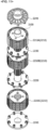
- the rotor 2200 may include a first holder 2230 and a second holder 2240.
- the first holder 2230 and the second holder 2240 serve to fix the magnet 2220 to the coupling hole 2211 without an adhesive.
- the first holder 2230 may be disposed between the first rotor core 2210A and the second rotor core 2210B or between the second rotor core 2210B and the third rotor core 2210C.
- the first holder 2230 may be disposed between the second rotor core 2210B disposed at the center and the first rotor core 2210A disposed on the top of the second rotor core 2210B.
- the first holder 2230 may be disposed between the second rotor core 2210B disposed at the center and the third rotor core 2210C disposed on the bottom of the second rotor core 2210B.
- the second rotor core 2210B disposed at the center may be interposed between the two first holders 2230.
- the second holder 2240 may be disposed on the top of the first rotor core 2210A disposed on the uppermost side. Alternatively, the second holder 2240 may be disposed on the bottom of the third rotor core 2210C disposed on the lowermost side. Two second holders 2240 may be disposed with the rotor core 2210 therebetween.
- FIG. 13 is a perspective view showing the first holder viewed from above.
- FIG. 14 is a perspective view showing the second holder viewed from below.
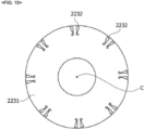
- FIG. 15 is a plan view of the first holder.
- the base plate 2231 may be formed in a disc shape.
- a through-hole 2231a is formed at a center of the base plate 2231.
- the rotating shaft 2100 passes through the through-hole 2231a.
- the first protrusions 2232 may protrude from an upper surface of the base plate 2231.
- the second protrusions 2233 may protrude from a lower surface of the base plate 2231.
- the first protrusions 2232 and the second protrusions 2233 are disposed at regular gaps with respect to the circumferential direction of the first holder 2230. Positions of the first protrusions 2232 and positions of the second protrusions 2233 correspond to positions of the gap portion (G in FIG. 9 ) of the coupling hole 2211 of the rotor core 2210.
- the first protrusion 2232 may be forcibly fitted into the coupling hole 2211 of the first rotor core 2210A disposed on the upper side.
- the plurality of first protrusions 2232 may be forcibly fitted into the gap portions (G in FIG. 9 ) of the coupling holes 2211 toward the low surface of the first rotor core 2210A disposed on the upper side, respectively.
- the plurality of second protrusions 2233 may be forcibly fitted into the gap portions (G in FIG. 9 ) of the coupling holes 2211 toward the upper surface of the second rotor core 2210B disposed at the center, respectively.
- the second protrusion 2233 may be forcibly fitted into the coupling hole 2211 of the third rotor core 2210C disposed on the lower side.
- the plurality of second projections 2233 may be forcibly fitted into the gap portions (G in FIG. 9 ) of the coupling holes 2211 toward the upper surface of the third rotor core 2210C disposed on the lower side, respectively.
- the plurality of first protrusions 2232 may be forcibly fitted into the gap portions (G in FIG. 9 ) of the coupling holes 2211 toward the lower surface of the second rotor core 2210B disposed at the center, respectively.
- the first protrusions 2232 may be shifted from the second protrusions 2233 with respect to the circumferential direction of the first holder 2230. This is because the first rotor core 2210A and the second rotor core 2210B or the second rotor core 2210B and the third rotor core 2210C are disposed to be shifted from each other to form a skew angle.
- Two first protrusions 2232 may be disposed in one coupling hole 2211.
- the number of the first protrusions 2232 disposed in the first holder 2230 may be double the number of the magnets 2220.
- two second protrusions 2233 may be disposed in one coupling hole 2211.
- the number of the second protrusions 2233 disposed in the first holder 2230 may be double the number of the magnets 2220.
- FIG. 16 is a view showing the first protrusion inserted into the coupling hole of the rotor core.
- the first protrusion 2232 is forcibly fitted into the gap portion G.
- the first protrusion 2232 disposed between the coupling hole 2211 and the magnet 2220 presses the magnet 2220 so that the magnet 2220 is fixed to the coupling hole 2211.
- the second protrusion 2233 is also forcibly fitted into the gap portion G in the same manner as the first protrusion 2232 so that the magnet 2220 is fixed to the coupling hole 2211.
- FIG. 17 is a view showing a shape of the first protrusion.
- a sectional shape of the first protrusion 2232 corresponds to a planar shape of the spacing space between the coupling hole 2211 and the magnet 2220.
- the sectional shape of the first protrusion 2232 may include a first region 10 and a second region 20.
- a sectional shape of the first region 10 may have a triangular shape as a whole.
- a first surface 11 of the first region 10 comes into contact with a side surface of the coupling hole 2211 of the rotor core 2210.
- a second surface 12 of the first region 10 comes into contact with an outer surface of the coupling hole 2211.
- a third surface 13 of the first region 10 comes into contact with a side surface of the magnet 2220.
- the second region 20 may correspond to a shape recessed around a corner defining a boundary between a side surface and an inner surface of the coupling hole 2211.
- a sectional shape of the second region 20 may be rectangular.
- the second region 20 may be connected to an inner end of the first region 10.
- a first protrusion 2232a which is coupled to the coupling hole 2211A disposed on one side
- a first protrusion 2232b which is coupled to the coupling hole 2211B disposed on the other side
- a distance W2 between the first protrusion 2232a and the first protrusion 2232b facing each other may be greater than a width W1 of the bridge portion 2212.
- a function, shape, and size of the second protrusion 2233 may be the same as those of the above first protrusion 2232.
- FIG. 18 is a perspective view showing the second holder viewed from above.
- FIG. 19 is a perspective view showing the second holder viewed from below.
- FIG. 20 is a plan view of the second holder.
- the second holder 2240 may include a second base plate 2241, third protrusions 2242, and a support portion 2243.
- the second base plate 2241 may be formed in a disc shape.
- a second through-hole 2241a is formed at a center of the second base plate 2241.
- the rotating shaft 2100 passes through the second through-hole 2241a.
- the third protrusions 2242 may protrude from a lower surface of the second base plate 2241.
- the lower surface of the second base plate 2241 refers to a surface that faces the upper surface or the lower surface of the rotor core 2210 when the second holder 2240 is mounted on the rotor core 2210.
- the third protrusions 2242 are disposed at regular gaps with respect to a circumferential direction of the second holder 2240. Positions of the third protrusions 2242 correspond to the positions of the gap portions (G in FIG. 9 ) of the coupling holes 2211 of the rotor core 2210.
- the shape and size of the third protrusion 2242 may be the same as the shape and size of the first protrusion 2232 or the shape and size of the second protrusion 2233.
- positions of the third protrusions 2242 correspond to the positions of the first protrusions 2232 and the second protrusions 2233.
- the second holder 2240 is coupled to the upper surface of the first rotor core 2210A
- the first holder 2230 is coupled to the lower surface of the first rotor core 2210A, with respect to the first rotor core 2210A.
- the position of the third protrusion 2242 of the second holder 2240 corresponds to the position of the first protrusion 2232 of the first holder 2230.
- the second holder 2240 is coupled to the lower surface of the third rotor core 2210C
- the first holder 2230 is coupled to the upper surface of the third rotor core 2210C.
- the position of the second protrusion 2242 of the second holder 2240 corresponds to the position of the second protrusion 2233 of the first holder 2230.
- the support portion 2243 may protrude from the upper surface of the second base plate 2241.
- the support portion 2243 may include a third through-hole 2243a disposed at a center thereof.
- the third through-hole 2243a communicates with the second through-hole 2241a.
- An inner diameter of the third through-hole 2243a may be the same as an outer diameter of the rotating shaft 2100.
- the support portion 2243 may support the bearing 2530 (in FIG. 8 ).
- the second holder 2240 may include a concave portion 2244.
- the concave portion 2244 may be formed to be concave on the upper surface of the second holder 2240.
- the concave portion 2244 may be disposed at regular gaps along the circumferential direction of the second holder 2240.
- the concave portion 2244 may be a weight reducing shape generated during injection molding. Accordingly, a weight of the second holder 2240 may be minimized.
Landscapes
- Engineering & Computer Science (AREA)
- Power Engineering (AREA)
- Chemical & Material Sciences (AREA)
- Combustion & Propulsion (AREA)
- Transportation (AREA)
- Mechanical Engineering (AREA)
- Permanent Field Magnets Of Synchronous Machinery (AREA)
- Iron Core Of Rotating Electric Machines (AREA)
Claims (5)
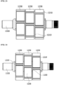
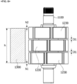
- Motor, umfassend:ein Gehäuse (1400);eine Drehwelle (1100), die sich entlang einer Axialrichtung erstreckt;einen Stator (1300), der im Gehäuse angeordnet ist und eine axiale Länge (h) in der Axialrichtung zwischen einer ersten Endfläche und einer zweiten Endfläche aufweist; undeinen Rotor (1200), der mit der Drehwelle (1100) gekoppelt und im Inneren des Stators angeordnet ist,wobei der Rotor (1200) einen Rotorkern (1210), der die Drehwelle (1100) umgibt, und eine Vielzahl von Magneten (1230) beinhaltet, die mit dem Rotorkern an einer Außenfläche desselben in einer geneigten Weise gekoppelt sind,wobei der Rotorkern eine Vielzahl von Rotorkernelementen (1210) umfasst,dadurch gekennzeichnet, dass die Rotorkernelemente (1210) in der Axialrichtung, mit vorbestimmten Spalten zwischen benachbarten Rotorkernelementen in der Axialrichtung, voneinander beabstandet sind,wobei die Spalte zwischen den Rotorkernelementen (1210) aus einem ersten Spalt undeinem zweiten Spalt zwischen Rotorkernelementen bestehen, und wobei der erste Spalt gleich dem zweiten Spalt ist,wobei die Magnete (1230) in der Axialrichtung voneinander beabstandet sind, wobei Spalte (D1) zwischen benachbarten Magneten in der Axialrichtung einander gleich sind,wobei die Summe der Spalte zwischen den Magneten (1230) im Bereich vom 0,04-bis 0,07-Fachen der axialen Länge des Stators (1300) liegt,wobei ein erster der Magnete (1230) in der Axialrichtung in Bezug auf die erste Endfläche des Stators (1300) um eine erste axiale Länge (h1) vorspringt, während ein zweiter der Magnete (1230) in der Axialrichtung in Bezug auf die zweite Endfläche des Stators (1300) um eine zweite axiale Länge (h2) vorspringt, undwobei die Summe der ersten und der zweiten axialen Länge (h1, h2) gleich der Summe der Spalte zwischen den Magneten (1230) ist.
- Motor nach Anspruch 1,
wobei die Summe der Spalte zwischen benachbarten Rotorkernelementen (1210) gleich der Summe der Spalte zwischen den Magneten (1230) ist. - Motor nach Anspruch 2, der Abstandshalter (1250) umfasst, die zwischen benachbarten Rotorkernelementen (1210) angeordnet sind, um die vorbestimmten Spalte zwischen den benachbarten Rotorkernelementen zu definieren,
wobei ein Außendurchmesser des Abstandshalters (1250) kleiner ist als ein Außendurchmesser des Rotorkerns. - Motor nach Anspruch 1, wobei die zweite axiale Länge (h2) gleich der ersten axialen Länge (h1) ist.
- Motor nach Anspruch 1, wobei die Summe der Spalte zwischen den Magneten (1230) im Bereich vom 0,05- bis 0,06-Fachen der axialen Länge des Stators (1300) liegt.
Applications Claiming Priority (3)
| Application Number | Priority Date | Filing Date | Title |
|---|---|---|---|
| KR1020170011092A KR102674223B1 (ko) | 2017-01-24 | 2017-01-24 | 모터 |
| KR1020170123555A KR102491351B1 (ko) | 2017-09-25 | 2017-09-25 | 모터 |
| PCT/KR2018/000681 WO2018139791A1 (ko) | 2017-01-24 | 2018-01-15 | 모터 |
Publications (3)
| Publication Number | Publication Date |
|---|---|
| EP3576254A1 EP3576254A1 (de) | 2019-12-04 |
| EP3576254A4 EP3576254A4 (de) | 2020-12-16 |
| EP3576254B1 true EP3576254B1 (de) | 2025-07-02 |
Family
ID=62979485
Family Applications (1)
| Application Number | Title | Priority Date | Filing Date |
|---|---|---|---|
| EP18744031.8A Active EP3576254B1 (de) | 2017-01-24 | 2018-01-15 | Motor |
Country Status (4)
| Country | Link |
|---|---|
| US (1) | US11670975B2 (de) |
| EP (1) | EP3576254B1 (de) |
| CN (1) | CN110214405B (de) |
| WO (1) | WO2018139791A1 (de) |
Families Citing this family (10)
| Publication number | Priority date | Publication date | Assignee | Title |
|---|---|---|---|---|
| DE102017223622A1 (de) * | 2017-12-21 | 2019-06-27 | Brose Fahrzeugteile GmbH & Co. Kommanditgesellschaft, Würzburg | Rotor für einen Elektromotor und Elektromotor |
| JP7538998B2 (ja) * | 2019-04-11 | 2024-08-23 | パナソニックIpマネジメント株式会社 | モータ及び電気機器 |
| JP7363296B2 (ja) * | 2019-09-30 | 2023-10-18 | ニデック株式会社 | ホルダ、ロータ、モータ、およびロータの製造方法 |
| KR102836888B1 (ko) * | 2019-12-23 | 2025-07-23 | 엘지이노텍 주식회사 | 모터 |
| KR102951770B1 (ko) * | 2019-12-23 | 2026-04-14 | 엘지이노텍 주식회사 | 모터 |
| JP7564213B2 (ja) * | 2019-12-23 | 2024-10-08 | エルジー イノテック カンパニー リミテッド | モータ |
| CN114846726B (zh) * | 2019-12-23 | 2026-04-24 | Lg伊诺特有限公司 | 马达 |
| CN112311175A (zh) * | 2020-05-29 | 2021-02-02 | 深圳市一吉制造有限公司 | 一种新型两定子四转子的组合节能电机 |
| US20240429760A1 (en) * | 2021-10-20 | 2024-12-26 | Mitsubishi Electric Corporation | Rotor, rotating electric machine, and electric power steering device |
| WO2026026071A1 (zh) * | 2024-07-30 | 2026-02-05 | 安徽威灵汽车部件有限公司 | 电动助力转向电机、电动助力转向系统和车辆 |
Citations (1)
| Publication number | Priority date | Publication date | Assignee | Title |
|---|---|---|---|---|
| US20150357892A1 (en) * | 2013-04-22 | 2015-12-10 | Mitsubishi Electric Corporation | Permanent magnet type motor |
Family Cites Families (16)
| Publication number | Priority date | Publication date | Assignee | Title |
|---|---|---|---|---|
| DE10357502A1 (de) * | 2003-12-09 | 2005-07-07 | BSH Bosch und Siemens Hausgeräte GmbH | Elektrische Maschine |
| CN100405711C (zh) | 2004-12-24 | 2008-07-23 | 西北工业大学 | 一种稀土永磁无刷直流牙科座椅电机 |
| CN2937563Y (zh) * | 2006-08-14 | 2007-08-22 | 苗佳琪 | 高效低耗潜水电泵 |
| JP2008160931A (ja) * | 2006-12-21 | 2008-07-10 | Brother Ind Ltd | モータ |
| JP4708448B2 (ja) * | 2008-03-04 | 2011-06-22 | 日立オートモティブシステムズ株式会社 | 回転電機および電気自動車 |
| DE102008041604A1 (de) * | 2008-08-27 | 2010-03-04 | Robert Bosch Gmbh | Rotor für eine elektrische Maschine mit reduziertem Rastmoment |
| KR101006809B1 (ko) * | 2008-09-30 | 2011-01-10 | 주식회사 마그네트휠 | 역기전력과 공극현상을 최소화시킨 고효율 전동기 |
| US20100231064A1 (en) * | 2009-03-11 | 2010-09-16 | Gm Global Technology Operations, Inc. | Balance ring for a vehicular electric machine |
| CN102055251A (zh) | 2009-11-06 | 2011-05-11 | 天津市松正电动科技有限公司 | 一种有效消除齿槽效应的永磁电机 |
| JP5241769B2 (ja) * | 2010-05-12 | 2013-07-17 | 三菱電機株式会社 | 電動式パワーステアリング装置用モータ |
| KR101239798B1 (ko) * | 2011-04-18 | 2013-03-06 | 차정환 | 자가보상 영구자석 모터 |
| JP2013099038A (ja) | 2011-10-28 | 2013-05-20 | Mitsuba Corp | 電動機用ロータおよびブラシレスモータ |
| JP2013102597A (ja) * | 2011-11-08 | 2013-05-23 | Mitsuba Corp | 電動機用ロータおよびブラシレスモータ |
| JP2014054047A (ja) * | 2012-09-06 | 2014-03-20 | Mitsuba Corp | ブラシレスモータ |
| WO2015005045A1 (ja) | 2013-07-09 | 2015-01-15 | 株式会社ミツバ | ロータ、及び電動モータ |
| JP6597184B2 (ja) * | 2015-10-29 | 2019-10-30 | アイシン精機株式会社 | 永久磁石型モータ |
-
2018
- 2018-01-15 EP EP18744031.8A patent/EP3576254B1/de active Active
- 2018-01-15 CN CN201880008306.8A patent/CN110214405B/zh active Active
- 2018-01-15 WO PCT/KR2018/000681 patent/WO2018139791A1/ko not_active Ceased
- 2018-01-15 US US16/480,450 patent/US11670975B2/en active Active
Patent Citations (1)
| Publication number | Priority date | Publication date | Assignee | Title |
|---|---|---|---|---|
| US20150357892A1 (en) * | 2013-04-22 | 2015-12-10 | Mitsubishi Electric Corporation | Permanent magnet type motor |
Also Published As
| Publication number | Publication date |
|---|---|
| CN110214405A (zh) | 2019-09-06 |
| EP3576254A1 (de) | 2019-12-04 |
| EP3576254A4 (de) | 2020-12-16 |
| WO2018139791A1 (ko) | 2018-08-02 |
| US20190386528A1 (en) | 2019-12-19 |
| CN110214405B (zh) | 2021-11-16 |
| US11670975B2 (en) | 2023-06-06 |
Similar Documents
| Publication | Publication Date | Title |
|---|---|---|
| US11670975B2 (en) | Motor having optimized gaps between magnets for improving cogging torque | |
| KR102644795B1 (ko) | 모터 | |
| US7705494B2 (en) | Electric motor | |
| KR102938744B1 (ko) | 모터 | |
| US11621595B2 (en) | Rotor plate, rotor, motor and vehicle including same | |
| JP2013102597A (ja) | 電動機用ロータおよびブラシレスモータ | |
| KR102547567B1 (ko) | 모터 | |
| JP7284177B2 (ja) | ロータおよびこれを具備するモータ | |
| EP4084296B1 (de) | Motor | |
| KR102682608B1 (ko) | 모터 | |
| JP2019068525A (ja) | モータ | |
| KR102547569B1 (ko) | 모터 | |
| KR20200114258A (ko) | 모터 | |
| EP4080734A1 (de) | Motor | |
| CN113169629B (zh) | 电机 | |
| CN111386650A (zh) | 马达 | |
| US11757318B2 (en) | Rotor and motor having same | |
| US11005333B2 (en) | Electric motor having a stator with a radially outside rotor with the rotor having a fan mounting portion comprising a noncontact region and a contract region configured to contact a mouting surface of a fan | |
| KR20200064531A (ko) | 모터 | |
| US11799336B2 (en) | Rotor and motor comprising same | |
| KR102491351B1 (ko) | 모터 | |
| KR20180089173A (ko) | 모터 | |
| KR102476480B1 (ko) | 로터 및 이를 구비하는 모터 | |
| EP4439932A1 (de) | Motor | |
| US10312771B2 (en) | Brushless motor |
Legal Events
| Date | Code | Title | Description |
|---|---|---|---|
| STAA | Information on the status of an ep patent application or granted ep patent |
Free format text: STATUS: THE INTERNATIONAL PUBLICATION HAS BEEN MADE |
|
| PUAI | Public reference made under article 153(3) epc to a published international application that has entered the european phase |
Free format text: ORIGINAL CODE: 0009012 |
|
| STAA | Information on the status of an ep patent application or granted ep patent |
Free format text: STATUS: REQUEST FOR EXAMINATION WAS MADE |
|
| 17P | Request for examination filed |
Effective date: 20190722 |
|
| AK | Designated contracting states |
Kind code of ref document: A1 Designated state(s): AL AT BE BG CH CY CZ DE DK EE ES FI FR GB GR HR HU IE IS IT LI LT LU LV MC MK MT NL NO PL PT RO RS SE SI SK SM TR |
|
| AX | Request for extension of the european patent |
Extension state: BA ME |
|
| DAV | Request for validation of the european patent (deleted) | ||
| DAX | Request for extension of the european patent (deleted) | ||
| A4 | Supplementary search report drawn up and despatched |
Effective date: 20201116 |
|
| RIC1 | Information provided on ipc code assigned before grant |
Ipc: H02K 21/22 20060101ALI20201110BHEP Ipc: H02K 1/27 20060101ALI20201110BHEP Ipc: H02K 21/14 20060101ALI20201110BHEP Ipc: H02K 1/28 20060101AFI20201110BHEP Ipc: H02K 7/00 20060101ALI20201110BHEP Ipc: B62D 5/04 20060101ALI20201110BHEP Ipc: H02K 21/16 20060101ALI20201110BHEP |
|
| STAA | Information on the status of an ep patent application or granted ep patent |
Free format text: STATUS: EXAMINATION IS IN PROGRESS |
|
| 17Q | First examination report despatched |
Effective date: 20220506 |
|
| GRAP | Despatch of communication of intention to grant a patent |
Free format text: ORIGINAL CODE: EPIDOSNIGR1 |
|
| STAA | Information on the status of an ep patent application or granted ep patent |
Free format text: STATUS: GRANT OF PATENT IS INTENDED |
|
| GRAS | Grant fee paid |
Free format text: ORIGINAL CODE: EPIDOSNIGR3 |
|
| INTG | Intention to grant announced |
Effective date: 20250428 |
|
| GRAA | (expected) grant |
Free format text: ORIGINAL CODE: 0009210 |
|
| STAA | Information on the status of an ep patent application or granted ep patent |
Free format text: STATUS: THE PATENT HAS BEEN GRANTED |
|
| AK | Designated contracting states |
Kind code of ref document: B1 Designated state(s): AL AT BE BG CH CY CZ DE DK EE ES FI FR GB GR HR HU IE IS IT LI LT LU LV MC MK MT NL NO PL PT RO RS SE SI SK SM TR |
|
| REG | Reference to a national code |
Ref country code: GB Ref legal event code: FG4D |
|
| REG | Reference to a national code |
Ref country code: CH Ref legal event code: EP |
|
| RAP4 | Party data changed (patent owner data changed or rights of a patent transferred) |
Owner name: LG INNOTEK CO., LTD. |
|
| REG | Reference to a national code |
Ref country code: DE Ref legal event code: R096 Ref document number: 602018083191 Country of ref document: DE |
|
| REG | Reference to a national code |
Ref country code: IE Ref legal event code: FG4D |
|
| REG | Reference to a national code |
Ref country code: NL Ref legal event code: MP Effective date: 20250702 |
|
| PG25 | Lapsed in a contracting state [announced via postgrant information from national office to epo] |
Ref country code: PT Free format text: LAPSE BECAUSE OF FAILURE TO SUBMIT A TRANSLATION OF THE DESCRIPTION OR TO PAY THE FEE WITHIN THE PRESCRIBED TIME-LIMIT Effective date: 20251103 |
|
| PG25 | Lapsed in a contracting state [announced via postgrant information from national office to epo] |
Ref country code: NL Free format text: LAPSE BECAUSE OF FAILURE TO SUBMIT A TRANSLATION OF THE DESCRIPTION OR TO PAY THE FEE WITHIN THE PRESCRIBED TIME-LIMIT Effective date: 20250702 |
|
| REG | Reference to a national code |
Ref country code: AT Ref legal event code: MK05 Ref document number: 1810413 Country of ref document: AT Kind code of ref document: T Effective date: 20250702 |
|
| PG25 | Lapsed in a contracting state [announced via postgrant information from national office to epo] |
Ref country code: IS Free format text: LAPSE BECAUSE OF FAILURE TO SUBMIT A TRANSLATION OF THE DESCRIPTION OR TO PAY THE FEE WITHIN THE PRESCRIBED TIME-LIMIT Effective date: 20251102 |
|
| PG25 | Lapsed in a contracting state [announced via postgrant information from national office to epo] |
Ref country code: NO Free format text: LAPSE BECAUSE OF FAILURE TO SUBMIT A TRANSLATION OF THE DESCRIPTION OR TO PAY THE FEE WITHIN THE PRESCRIBED TIME-LIMIT Effective date: 20251002 |
|
| REG | Reference to a national code |
Ref country code: LT Ref legal event code: MG9D |
|
| PG25 | Lapsed in a contracting state [announced via postgrant information from national office to epo] |
Ref country code: AT Free format text: LAPSE BECAUSE OF FAILURE TO SUBMIT A TRANSLATION OF THE DESCRIPTION OR TO PAY THE FEE WITHIN THE PRESCRIBED TIME-LIMIT Effective date: 20250702 |
|
| PG25 | Lapsed in a contracting state [announced via postgrant information from national office to epo] |
Ref country code: FI Free format text: LAPSE BECAUSE OF FAILURE TO SUBMIT A TRANSLATION OF THE DESCRIPTION OR TO PAY THE FEE WITHIN THE PRESCRIBED TIME-LIMIT Effective date: 20250702 |
|
| PG25 | Lapsed in a contracting state [announced via postgrant information from national office to epo] |
Ref country code: HR Free format text: LAPSE BECAUSE OF FAILURE TO SUBMIT A TRANSLATION OF THE DESCRIPTION OR TO PAY THE FEE WITHIN THE PRESCRIBED TIME-LIMIT Effective date: 20250702 |
|
| PG25 | Lapsed in a contracting state [announced via postgrant information from national office to epo] |
Ref country code: GR Free format text: LAPSE BECAUSE OF FAILURE TO SUBMIT A TRANSLATION OF THE DESCRIPTION OR TO PAY THE FEE WITHIN THE PRESCRIBED TIME-LIMIT Effective date: 20251003 |
|
| PG25 | Lapsed in a contracting state [announced via postgrant information from national office to epo] |
Ref country code: SE Free format text: LAPSE BECAUSE OF FAILURE TO SUBMIT A TRANSLATION OF THE DESCRIPTION OR TO PAY THE FEE WITHIN THE PRESCRIBED TIME-LIMIT Effective date: 20250702 Ref country code: CZ Free format text: LAPSE BECAUSE OF FAILURE TO SUBMIT A TRANSLATION OF THE DESCRIPTION OR TO PAY THE FEE WITHIN THE PRESCRIBED TIME-LIMIT Effective date: 20250702 |
|
| PG25 | Lapsed in a contracting state [announced via postgrant information from national office to epo] |
Ref country code: LV Free format text: LAPSE BECAUSE OF FAILURE TO SUBMIT A TRANSLATION OF THE DESCRIPTION OR TO PAY THE FEE WITHIN THE PRESCRIBED TIME-LIMIT Effective date: 20250702 |
|
| PG25 | Lapsed in a contracting state [announced via postgrant information from national office to epo] |
Ref country code: BG Free format text: LAPSE BECAUSE OF FAILURE TO SUBMIT A TRANSLATION OF THE DESCRIPTION OR TO PAY THE FEE WITHIN THE PRESCRIBED TIME-LIMIT Effective date: 20250702 Ref country code: PL Free format text: LAPSE BECAUSE OF FAILURE TO SUBMIT A TRANSLATION OF THE DESCRIPTION OR TO PAY THE FEE WITHIN THE PRESCRIBED TIME-LIMIT Effective date: 20250702 |
|
| PG25 | Lapsed in a contracting state [announced via postgrant information from national office to epo] |
Ref country code: RS Free format text: LAPSE BECAUSE OF FAILURE TO SUBMIT A TRANSLATION OF THE DESCRIPTION OR TO PAY THE FEE WITHIN THE PRESCRIBED TIME-LIMIT Effective date: 20251002 |
|
| PG25 | Lapsed in a contracting state [announced via postgrant information from national office to epo] |
Ref country code: ES Free format text: LAPSE BECAUSE OF FAILURE TO SUBMIT A TRANSLATION OF THE DESCRIPTION OR TO PAY THE FEE WITHIN THE PRESCRIBED TIME-LIMIT Effective date: 20250702 |
|
| PG25 | Lapsed in a contracting state [announced via postgrant information from national office to epo] |
Ref country code: SM Free format text: LAPSE BECAUSE OF FAILURE TO SUBMIT A TRANSLATION OF THE DESCRIPTION OR TO PAY THE FEE WITHIN THE PRESCRIBED TIME-LIMIT Effective date: 20250702 |
|
| PG25 | Lapsed in a contracting state [announced via postgrant information from national office to epo] |
Ref country code: DK Free format text: LAPSE BECAUSE OF FAILURE TO SUBMIT A TRANSLATION OF THE DESCRIPTION OR TO PAY THE FEE WITHIN THE PRESCRIBED TIME-LIMIT Effective date: 20250702 |
|
| PGFP | Annual fee paid to national office [announced via postgrant information from national office to epo] |
Ref country code: DE Payment date: 20251222 Year of fee payment: 9 |
|
| PG25 | Lapsed in a contracting state [announced via postgrant information from national office to epo] |
Ref country code: IT Free format text: LAPSE BECAUSE OF FAILURE TO SUBMIT A TRANSLATION OF THE DESCRIPTION OR TO PAY THE FEE WITHIN THE PRESCRIBED TIME-LIMIT Effective date: 20250702 |
|
| PG25 | Lapsed in a contracting state [announced via postgrant information from national office to epo] |
Ref country code: SK Free format text: LAPSE BECAUSE OF FAILURE TO SUBMIT A TRANSLATION OF THE DESCRIPTION OR TO PAY THE FEE WITHIN THE PRESCRIBED TIME-LIMIT Effective date: 20250702 Ref country code: EE Free format text: LAPSE BECAUSE OF FAILURE TO SUBMIT A TRANSLATION OF THE DESCRIPTION OR TO PAY THE FEE WITHIN THE PRESCRIBED TIME-LIMIT Effective date: 20250702 |
|
| PLBE | No opposition filed within time limit |
Free format text: ORIGINAL CODE: 0009261 |
|
| STAA | Information on the status of an ep patent application or granted ep patent |
Free format text: STATUS: NO OPPOSITION FILED WITHIN TIME LIMIT |