EP3573735B1 - Filtervorrichtung - Google Patents
Filtervorrichtung Download PDFInfo
- Publication number
- EP3573735B1 EP3573735B1 EP18700038.5A EP18700038A EP3573735B1 EP 3573735 B1 EP3573735 B1 EP 3573735B1 EP 18700038 A EP18700038 A EP 18700038A EP 3573735 B1 EP3573735 B1 EP 3573735B1
- Authority
- EP
- European Patent Office
- Prior art keywords
- filter
- vacuum chamber
- fluid
- filter housing
- valve
- Prior art date
- Legal status (The legal status is an assumption and is not a legal conclusion. Google has not performed a legal analysis and makes no representation as to the accuracy of the status listed.)
- Active
Links
Images




Classifications
-
- B—PERFORMING OPERATIONS; TRANSPORTING
- B01—PHYSICAL OR CHEMICAL PROCESSES OR APPARATUS IN GENERAL
- B01D—SEPARATION
- B01D19/00—Degasification of liquids
- B01D19/0031—Degasification of liquids by filtration
-
- B—PERFORMING OPERATIONS; TRANSPORTING
- B01—PHYSICAL OR CHEMICAL PROCESSES OR APPARATUS IN GENERAL
- B01D—SEPARATION
- B01D19/00—Degasification of liquids
- B01D19/0036—Flash degasification
-
- B—PERFORMING OPERATIONS; TRANSPORTING
- B01—PHYSICAL OR CHEMICAL PROCESSES OR APPARATUS IN GENERAL
- B01D—SEPARATION
- B01D19/00—Degasification of liquids
- B01D19/0063—Regulation, control including valves and floats
-
- B—PERFORMING OPERATIONS; TRANSPORTING
- B01—PHYSICAL OR CHEMICAL PROCESSES OR APPARATUS IN GENERAL
- B01D—SEPARATION
- B01D29/00—Filters with filtering elements stationary during filtration, e.g. pressure or suction filters, not covered by groups B01D24/00 - B01D27/00; Filtering elements therefor
- B01D29/11—Filters with filtering elements stationary during filtration, e.g. pressure or suction filters, not covered by groups B01D24/00 - B01D27/00; Filtering elements therefor with bag, cage, hose, tube, sleeve or like filtering elements
- B01D29/13—Supported filter elements
- B01D29/15—Supported filter elements arranged for inward flow filtration
-
- B—PERFORMING OPERATIONS; TRANSPORTING
- B01—PHYSICAL OR CHEMICAL PROCESSES OR APPARATUS IN GENERAL
- B01D—SEPARATION
- B01D29/00—Filters with filtering elements stationary during filtration, e.g. pressure or suction filters, not covered by groups B01D24/00 - B01D27/00; Filtering elements therefor
- B01D29/88—Filters with filtering elements stationary during filtration, e.g. pressure or suction filters, not covered by groups B01D24/00 - B01D27/00; Filtering elements therefor having feed or discharge devices
- B01D29/92—Filters with filtering elements stationary during filtration, e.g. pressure or suction filters, not covered by groups B01D24/00 - B01D27/00; Filtering elements therefor having feed or discharge devices for discharging filtrate
-
- B—PERFORMING OPERATIONS; TRANSPORTING
- B01—PHYSICAL OR CHEMICAL PROCESSES OR APPARATUS IN GENERAL
- B01D—SEPARATION
- B01D29/00—Filters with filtering elements stationary during filtration, e.g. pressure or suction filters, not covered by groups B01D24/00 - B01D27/00; Filtering elements therefor
- B01D29/88—Filters with filtering elements stationary during filtration, e.g. pressure or suction filters, not covered by groups B01D24/00 - B01D27/00; Filtering elements therefor having feed or discharge devices
- B01D29/92—Filters with filtering elements stationary during filtration, e.g. pressure or suction filters, not covered by groups B01D24/00 - B01D27/00; Filtering elements therefor having feed or discharge devices for discharging filtrate
- B01D29/925—Filters with filtering elements stationary during filtration, e.g. pressure or suction filters, not covered by groups B01D24/00 - B01D27/00; Filtering elements therefor having feed or discharge devices for discharging filtrate containing liquid displacement elements or cores
-
- B—PERFORMING OPERATIONS; TRANSPORTING
- B01—PHYSICAL OR CHEMICAL PROCESSES OR APPARATUS IN GENERAL
- B01D—SEPARATION
- B01D35/00—Filtering devices having features not specifically covered by groups B01D24/00 - B01D33/00, or for applications not specifically covered by groups B01D24/00 - B01D33/00; Auxiliary devices for filtration; Filter housing constructions
- B01D35/14—Safety devices specially adapted for filtration; Devices for indicating clogging
- B01D35/147—Bypass or safety valves
- B01D35/1475—Pressure relief valves or pressure control valves
-
- B—PERFORMING OPERATIONS; TRANSPORTING
- B01—PHYSICAL OR CHEMICAL PROCESSES OR APPARATUS IN GENERAL
- B01D—SEPARATION
- B01D36/00—Filter circuits or combinations of filters with other separating devices
- B01D36/001—Filters in combination with devices for the removal of gas, air purge systems
Definitions
- the invention relates to a filter device, in particular for the filtration of hydraulic media.
- Filter devices of the above type as part of hydraulic systems are prior art.
- the filter devices In order to avoid impairments of safety-relevant components, such as valves, hydraulic drives, control elements and the like, it is essential that the filter devices guarantee a constant quality of the filtered media. Proper functioning of the filter devices in the system is therefore a basic requirement for operational safety.
- the DE 31 08 948 A1 discloses a filter device, in particular for the filtration of hydraulic media, with a filter housing and a filter element arranged therein, with the air in the filter housing being able to be removed by suction from the filter housing by means of a degassing device that generates a negative pressure, the degassing device having a vacuum chamber, a jet pump and a Has valve device that brings air from the filter housing into the vacuum chamber, wherein the degassing device has a removal device that acts as a diaphragm or throttle, the air in addition or alternatively to the valve device or allows oil to flow from the filter housing into the vacuum chamber, with the vacuum chamber being permanently connected to the removal device on the inlet side and also being permanently connected to the jet pump on the outlet side, the filter housing being suitable for accommodating filter elements which are installed from the outside in or from the inside the fluid to be cleaned can flow through to the outside.
- the EP 0 856 345 A1 , the WO 2014/131420 A1 and the WO 2010/118803 A1 describe further filter devices.
- the object of the invention is to make available a filter device which particularly meets the operational requirements.
- the filter device is characterized in that it has a filter housing and a filter element arranged therein, with the air in the filter housing being able to be removed by suction by means of a degassing device that generates a negative pressure, the degassing device having a vacuum chamber, a jet pump and a valve device, in particular in the form of a slide valve, which brings air from the filter housing into the vacuum chamber and closes the relevant flow path when hydraulic medium flows in, the degassing device having an extraction device which acts as an orifice plate or throttle, which acts in addition or as an alternative to the valve device Air or oil can flow from the filter housing into the vacuum chamber, the vacuum chamber being permanently connected to the valve device and/or the removal device on the input side and also permanently to the output side Jet pump is connected, with the filter housing for the intake of filter elements is suitable, through which the fluid to be cleaned can flow from the outside in or from the inside out, wherein for the first alternative, a channel guide is provided in an upper end cap of the filter element
- suction can be formed from two different regions of the filter housing.
- the jet pump can be actuated by means of a media flow, which is generated in particular by a hydraulic pump, such as a gear pump.
- the jet pump can be actuated by an external flow of media or advantageously by a flow of media formed from the filtrate of the device.
- Such valve means is preferably media controlled, i.e. responsive to the air/hydraulic fluid viscosity difference.
- the outlet side of the jet pump is connected to a guide device, preferably with a check valve interposed, which guides the fluid flow of the jet pump above the fluid level of a fluid container in which the filter housing is arranged, along the container wall, forming a fluid film.
- a particularly effective air separation from the fluid film lying against the tank wall can be achieved by such a tank-side introduction of the oil/air mixture from the jet pump.
- the non-return valve prevents possible ventilation of the filter housing from the tank space located above the fluid level.
- a pressure sensor or pressure switch can be connected to the vacuum chamber, which serves to monitor the vacuum degassing.
- the status of the degassing device can be monitored by connecting to the relevant machine control.
- the vacuum chamber and/or the valve device can be part of a head part of the filter housing that seals off the fluid container from the outside.
- the filter device including the degassing device, forms a uniform, compact structure.
- the filter device is part of a semi-closed hydraulic system having a tank system.
- the 1 shows the exemplary embodiment with a filter housing 4 installed in a small-volume tank 2 storing a volume of fluid.
- a housing head part 12 that seals the tank 2 at the top, the upper end of which is formed by a closure cover 14 screwed to the head part 12 .
- the filter housing 4, which extends coaxially in the tank 2, is held at its upper open end with a folded-over end edge 16 on the housing head part 12 and is sealed on this by a sealing ring 18.
- the lower end of the filter housing 4 is followed by an outlet chamber 20 which forms the fluid connection to a fluid outlet 22 on the bottom part 6 of the tank 2 .
- the outlet chamber 20 has an axial height which corresponds to approximately one fifth of the height of the tank 2 .
- the 9 shows in isolation the upper end cap 24 which has a skirt 26 ( 9 ) for the upper end of the filter media 28 ( 4 and 5 ) of the filter element 30 accommodated in the filter housing 4 and a seat for a bypass valve 48 forms.
- the end cap 24, which is injection molded in one piece from plastic material, has a ring of wing-like ribs 32 (not all numbered) extending from the skirt 26 and expanding the end cap 24 upwards in a basket-like manner and merging into an upper annular body 34 which is inserted into the tank at 2 built-in filter element 30 is clamped between the top 36 of the head part 12 and the cover 14, s.
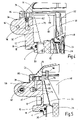
- Figures 4 and 5 are .
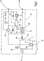
- the 2 shows the hydraulic circuit of the filter device in a symbolic representation.
- the 1 clarifies the operation of the filter device by means of flow arrows 38, in which the unfiltrate reaches the interior 40 in the head part 12 via an inlet 39 located on the head part 12, from where the unfiltrate flows into the space between the filter housing 4 and the outside of the filter material 28 of the filter element 30 and flows through the filter medium 28 from the outside to the inside.
- the filtrate formed flows into the outlet chamber 20, in which a screen basket 42 is located between the chamber inlet and the fluid outlet 22, from which the filtrate can be discharged.
- the outer wall of the outlet chamber 20 is formed by a screen cylinder 44 through which the filtrate also reaches the interior of the tank 2 .
- the outflow rate at the outlet 22 is set in such a way that, given the quantity of unfiltrate flowing into the head part 12, a liquid level of the desired level is set in the interior of the tank 2.
- An opto-electric level switch 41 on tank 2 ( 2 ) be provided.
- a contamination indicator 46 and the bypass valve 48 are assigned to the filter element 30 in the manner customary in filter devices.
- the tank 2 has a tank ventilation 50 which is likewise designed in a conventional manner.
- the opto-electrical level switch 41 which is part of the machine control, allows the maintenance of the desired fluid level in the tank 2 during operation by controlling the filtrate outflow at the outlet 22.
- With 52 is in the circuit of 2 designates a degassing device which is connected to the filter element 30 and whose structure is shown in FIG Figures 3 to 8 is shown in more detail.
- the jet pump 54 has a pressure connection 58 for the supply of a media stream that actuates it, via which a media stream under a pressure of 25 bar to 40 bar, in the present example filtrate from the filter device, is supplied by a pump (not shown), such as a gear pump , with a flow rate of 3.5 l/min from a jet nozzle 60 in a mixing chamber 62 of the jet pump 54 is supplied.
- a pump such as a gear pump
- the mixing chamber 62 is followed by a diffuser 64, at the end of which a check valve 66 is arranged in front of an outlet connection 68, from which the media flow operating the pump 54 emerges at a pressure of 1 bar.
- the vacuum chamber 56 is connected via a duct 70 to the mixing chamber 62 to which is also connected a pressure switch sensor 72 which is in communication with the machine controller for operational monitoring control.
- a valve device is connected to the end of the vacuum chamber 56 next to the diffuser 64 of the jet pump 54, in the present example in the form of a slide valve 74.
- channel 76 shows the ends of the channels 76 and 78 which are exposed on the upper side 36 of the head part 12 continue in radially projecting projections 84 and 86, respectively, of the annular body 34 of the end cap 24.
- channel 76 shows the 4 Channels 88 and 90, which are formed in the end cap 24 and lead to the inner filter cavity 92 of the filter element 30, which forms the inflow side when the filter medium 28 flows through from the inside to the outside.
- channel 78 shows the figure 5 a duct 94 leading via a vertical suction tube 96 to the top of the housing within cover 14.
- the spool valve 74 is by a compression spring 100 in the 8 shown biased open position in which the channel 78 with the vacuum chamber 56 is connected.
- the spring 100 keeps the slide valve 74 in the open state against the suction pressure of the vacuum chamber 56 due to the compressibility of air, see FIG. 8 .
- the slide valve 74 closes, see FIG. 7 .
- a liquid/air mixture is drawn into the vacuum chamber 56 via the throttle 82 in the channel 76 from the highest point of the housing, as is air which is sucked off via the slide valve 74 and the channel 78 from the inflow side of the filter element 30.
- the jet pump 54 sucks these media via the channel 70 from the vacuum chamber 56 into the mixing chamber 62, from which they are expelled together with the media flow operating the jet pump 54 from the diffuser 64 of the jet pump 54 via the check valve 66 at the connection 68.
- This is via a flexible line 98 ( 10 ) connected to a flow guide device 102.
- This is arranged on the wall of the curved upper part of the tank 8 and is located inside the tank in an in 10 outflow nozzle, which is not visible, from which the air-liquid mixture sucked off by means of the degassing device 52 is guided tangentially in the circumferential direction along the inside of the tank wall, so that a fluid film forms on the tank wall. This results in a particularly effective air separation from the media mixture.
- the non-return valve 66 located in front of the outflow connection on the diffuser 64 of the jet pump 54 prevents a possible backflow when the system is at a standstill and if the fill level of the tank 2 exceeds the mouth of
Landscapes
- Chemical & Material Sciences (AREA)
- Chemical Kinetics & Catalysis (AREA)
- Degasification And Air Bubble Elimination (AREA)
- Filtration Of Liquid (AREA)
- Jet Pumps And Other Pumps (AREA)
- Details Of Reciprocating Pumps (AREA)
Description
- Die Erfindung betrifft eine Filtervorrichtung, insbesondere zur Filtration von Hydraulikmedien.
- Filtervorrichtungen der vorstehenden Gattung als Bestandteil von Hydrauliksystemen sind Stand der Technik. Zur Vermeidung von Beeinträchtigungen sicherheitsrelevanter Komponenten, wie Ventile, hydraulische Antriebe, Steuerelemente und dergleichen, ist wesentliche Voraussetzung, dass die Filtervorrichtungen eine gleichbleibende Qualität der filtrierten Medien gewährleisten. Die einwandfreie Funktion der im System befindlichen Filtervorrichtungen ist daher für die Betriebssicherheit eine Grundbedingung.
- Die
DE 31 08 948 A1 offenbart eine Filtervorrichtung, insbesondere zur Filtration von Hydraulikmedien, mit einem Filtergehäuse und einem darin angeordneten Filterelement, wobei mittels einer Entgasungseinrichtung, die einen Unterdruck erzeugt, im Filtergehäuse befindliche Luft durch Absaugen aus diesem entfernbar ist, wobei die Entgasungseinrichtung eine Vakuumkammer, eine Strahlpumpe und eine Ventileinrichtung aufweist, die Luft aus dem Filtergehäuse in die Vakuumkammer verbringt, wobei die Entgasungseinrichtung eine Entnahmeeinrichtung aufweist, die als Blende oder Drossel wirkt, die zusätzlich oder alternativ zu der Ventileinrichtung Luft oder Öl aus dem Filtergehäuse in die Vakuumkammer strömen lässt, wobei die Vakuumkammer eingangsseitig an die Entnahmeeinrichtung permanent angeschlossen ist und ausgangsseitig ebenfalls permanent an die Strahlpumpe angeschlossen ist, wobei das Filtergehäuse für die Aufnahme von Filterelementen geeignet ist, die von außen nach innen oder von innen nach außen von dem abzureinigenden Fluid durchströmbar sind. - Die
EP 0 856 345 A1 , dieWO 2014/131420 A1 und dieWO 2010/118803 A1 beschreiben weitere Filtervorrichtungen. - Im Hinblick hierauf stellt sich die Erfindung die Aufgabe, eine Filtervorrichtung zur Verfügung zu stellen, die den betrieblichen Anforderungen in besonderem Maße gerecht wird.
- Erfindungsgemäß ist diese Aufgabe durch eine Filtervorrichtung mit den im Patentanspruch 1 angegebenen Merkmalen gelöst.
- Demgemäß ist die erfindungsgemäße Filtervorrichtung dadurch charakterisiert, dass diese ein Filtergehäuse und ein darin angeordnetes Filterelement aufweist, wobei mittels einer Entgasungseinrichtung, die einen Unterdruck erzeugt, im Filtergehäuse befindliche Luft durch Absaugen aus diesem entfernbar ist, wobei die Entgasungseinrichtung eine Vakuumkammer, eine Strahlpumpe und eine Ventileinrichtung, insbesondere in der Art eines Schieberventils, aufweist, die Luft aus dem Filtergehäuse in die Vakuumkammer verbringt und bei nachströmendem Hydraulikmedium den dahingehenden Strömungsweg verschließt, wobei die Entgasungseinrichtung eine Entnahmeeinrichtung aufweist, die als Blende oder Drossel wirkt, die zusätzlich oder alternativ zu der Ventileinrichtung Luft oder Öl aus dem Filtergehäuse in die Vakuumkammer strömen lässt, wobei die Vakuumkammer eingangsseitig an die Ventileinrichtung und/oder die Entnahmeeinrichtung permanent angeschlossen ist und ausgangsseitig ebenfalls permanent an die Strahlpumpe angeschlossen ist, wobei das Filtergehäuse für die Aufnahme von Filterelementen geeignet ist, die von außen nach innen oder von innen nach außen von dem abzureinigenden Fluid durchströmbar sind, wobei für die erste Alternative in einer oberen Endkappe des Filterelements eine Kanalführung vorgesehen ist, die von der höchsten Stelle des Fluidbehälters zur Vakuumkammer führt, wobei für die zweite Alternative in der Endkappe Kanäle vorgesehen sind, die von der Anströmseite des Filterelements zur Vakuumkammer führen, und wobei die Kanalführung zu einer Steuerkammer der Ventileinrichtung führt und die Kanäle der Endkappe an die Vakuumkammer, vorzugsweise über die als Entnahmeeinrichtung dienende Blende oder Drossel, angeschlossen sind.
- Dadurch ist eine Absaugung aus zwei voneinander verschiedenen Regionen des Filtergehäuses ausbildbar.
- Ferner ist vorgesehen, dass mittels einer Entgasungseinrichtung, die einen Unterdruck erzeugt, im Filtergehäuse befindliche Luft durch Absaugen aus diesem entfernbar ist. Dadurch ist die Gefahr vermieden, dass durch im Fluid mitgeführte Luft die Steifigkeit hydraulischer Antriebe oder Stelleinrichtungen oder die Funktionsfähigkeit von Ventilen beeinträchtigt wird. Die Abscheidung von Luft aus Fluiden im Allgemeinen ist Stand der Technik, siehe beispielsweise
DE 10 2012 000 221 A1 . Das dort aufgezeigte Verfahren zur Abtrennung von Gas aus einem in einem Reservoir bevorrateten Medium durch Erzeugen eines Differenzdrucks zwischen dem Reservoir und einem weiteren Reservoir ist auf Filtervorrichtungen nicht übertragbar. Die Erfindung sieht demgegenüber das Entfernen von Luft durch direktes Absaugen aus dem Filtergehäuse mittels einer Entgasungseinrichtung vor. - Die Strahlpumpe kann mittels eines Medienstroms, der insbesondere von einer Hydropumpe, wie einer Zahnradpumpe, erzeugt ist, betätigbar sein. Die Strahlpumpe kann hierbei durch einen externen Medienstrom oder in vorteilhafter Weise durch einen aus dem Filtrat der Vorrichtung gebildeten Medienstrom betätigt sein.
- Die derartige Ventileinrichtung ist vorzugsweise mediengesteuert, d.h. sie spricht auf den Viskositätsunterschied Luft/Hydraulikfluid an.
- Bei vorteilhaften Ausführungsbeispielen ist die Ausgangsseite der Strahlpumpe, vorzugsweise unter Zwischenschalten eines Rückschlagventils, an eine Führungseinrichtung angeschlossen, die den Fluidstrom der Strahlpumpe oberhalb des Fluidspiegels eines Fluidbehälters, in dem das Filtergehäuse angeordnet ist, entlang der Behälterwand unter Bildung eines Fluidfilms führt. Bei einer Filtervorrichtung, bei der das Filtergehäuse in einem ein Fluidvolumen bevorratenden Tank angeordnet ist, lässt sich durch eine derartige, tankseitige Einleitung des Öl/Luftgemisches aus der Strahlpumpe eine besonders effektive Luftseparation aus dem an der Tankwand anliegenden Fluidfilm erreichen. Gleichzeitig verhindert das Rückschlagventil eine mögliche Belüftung des Filtergehäuses aus dem oberhalb des Fluidpegels gelegenen Raum des Tanks.
- Mit besonderem Vorteil kann an die Vakuumkammer ein Drucksensor oder Druckschalter angeschlossen sein, der jeweils zur Überwachung der Vakuumentgasung dient. Durch Anbindung an die betreffende Maschinensteuerung ist der Status der Entgasungseinrichtung überwachbar.
- Die Vakuumkammer und/oder die Ventileinrichtung können Bestandteil eines den Fluidbehälter nach außen hin abschließenden Kopfteils des Filtergehäuses sein. Die Filtervorrichtung bildet dadurch, einschließlich der Entgasungseinrichtung, einen einheitlichen, kompakten Baukörper.
- Nachstehend ist die Erfindung anhand eines in der Zeichnung dargestellten Ausführungsbeispiels im Einzelnen erläutert. Es zeigen:
- Fig. 1
- einen schematisch vereinfachten Vertikalschnitt eines Ausführungsbeispiels der erfindungsgemäßen Filtervorrichtung;
- Fig. 2
- in Symboldarstellung die Hydraulikschaltung des Ausführungs-beispiels;
- Fig. 3
- einen Horizontalschnitt mit in einem Gehäuse-Kopfteil des Aus-führungsbeispiels liegender Schnittebene;
- Fig. 4
- einen Vertikalschnitt eines seitlichen Längenabschnitts des Aus-führungsbeispiels im Bereich des Gehäuse-Kopfteils;
- Fig. 5
- einen der
Fig. 4 entsprechenden Vertikalschnitt mit gegenüberFig. 4 um 30° verdrehter Schnittebene; - Fig. 6
- eine teilweise aufgeschnittene perspektivische Schrägansicht des eine Entgasungseinrichtung aufweisenden Bereichs des Gehäuse-Kopfteils des Ausführungsbeispiels;
- Fig. 7
- eine Teilansicht des eine Ventileinrichtung aufweisenden Bereichs der Entgasungseinrichtung von
Fig. 6 , wobei die Ventileinrichtung geschlossen dargestellt ist; - Fig. 8
- eine der
Fig. 7 entsprechende Darstellung, wobei sich die Ventileinrichtung im geöffneten Zustand befindet; - Fig. 9
- eine perspektivische Schrägansicht der oberen Endkappe des Filterelements des Ausführungsbeispiels; und
- Fig. 10
- eine abgebrochen gezeichnete perspektivische Schrägansicht des unterhalb des Gehäuse-Kopfteils befindlichen Bereichs des Fluidbehälters des Ausführungsbeispiels mit einer Führungseinrichtung zum Einleiten eines Fluidstroms in den Behälter.
- Nachstehend ist anhand der Zeichnung die Erfindung an einem Ausführungsbeispiel beschrieben, bei dem die Filtervorrichtung Bestandteil eines halb geschlossenen, ein Tanksystem aufweisenden Hydrauliksystems ist. Die
Fig. 1 zeigt das Ausführungsbeispiel mit in einen kleinvolumigen, ein Fluidvolumen bevorratenden Tank 2 eingebautem Filtergehäuse 4. Der kreiszylindrische Tank 2 weist ein gewölbtes, unteres Bodenteil 6 und ein entsprechend gewölbtes Oberteil 8 auf, das in ein zur Behälterhochachse koaxiales Behälterhalsteil 10 übergeht. An dieses schließt sich ein den Tank 2 nach oben hin abschließendes Gehäuse-Kopfteil 12 an, dessen oberer Abschluss durch einen mit dem Kopfteil 12 verschraubten Verschlussdeckel 14 gebildet ist. Das Filtergehäuse 4, das sich im Tank 2 koaxial erstreckt, ist mit seinem oberen offenen Ende mit einem umgelegten Endrand 16 am Gehäuse-Kopfteil 12 gehalten und an diesem durch einen Dichtring 18 abgedichtet. An das untere Ende des Filtergehäuses 4 schließt sich eine Ausgangskammer 20 an, die die Fluidverbindung zu einem Fluidauslass 22 am Bodenteil 6 des Tanks 2 bildet. Die Ausgangskammer 20 besitzt eine axiale Höhe, die etwa einem Fünftel der Höhe des Tanks 2 entspricht. - Die
Fig. 9 zeigt in gesonderter Darstellung die obere Endkappe 24, die eine Einfassung 26 (Fig. 9 ) für das obere Ende des Filtermediums 28 (Fig. 4 und Fig. 5 ) des im Filtergehäuse 4 aufgenommenen Filterelements 30 sowie einen Sitz für ein Bypassventil 48 bildet. Die aus Kunststoffmaterial einstückig spritzgeformte Endkappe 24 weist, von der Einfassung 26 ausgehend, einen Kranz von flügelartigen Rippen 32 (nicht sämtliche beziffert) auf, die die Endkappe 24 korbartig nach oben hin erweitern und in einen oberen Ringkörper 34 übergehen, der bei in den Tank 2 eingebautem Filterelement 30 zwischen der Oberseite 36 des Kopfteils 12 und dem Deckel 14 eingespannt ist, s.Fig. 4 und 5 . - Die
Fig. 2 zeigt in Symboldarstellung die Hydraulikschaltung der Filtervorrichtung. DieFig. 1 verdeutlicht durch Strömungspfeile 38 den Betrieb der Filtervorrichtung, bei dem Unfiltrat über einen am Kopfteil 12 befindlichen Einlass 39 in den Innenraum 40 im Kopfteil 12 gelangt, von wo das Unfiltrat in den Zwischenraum zwischen Filtergehäuse 4 und Außenseite des Filtermaterials 28 des Filterelements 30 einströmt und das Filtermedium 28 von außen nach innen durchströmt. Das gebildete Filtrat strömt in die Ausgangskammer 20, in der sich ein Siebkorb 42 zwischen Kammereingang und dem Fluidauslass 22 befindet, aus dem das Filtrat abführbar ist. Die Außenwand der Ausgangskammer 20 ist durch einen Siebzylinder 44 gebildet, durch den Filtrat auch zum Innenraum des Tanks 2 gelangt. Im Betrieb ist die Ausströmrate am Auslass 22 derart eingestellt, dass sich bei der in das Kopfteil 12 einströmenden Menge des Unfiltrats im Innenraum des Tanks 2 ein Flüssigkeitspegel gewünschten Höhenniveaus einstellt. Für die diesbezügliche Maschinensteuerung kann ein opto-elektrischer Niveauschalter 41 am Tank 2 (Fig. 2 ) vorgesehen sein. - Wie in
Fig. 2 gezeigt, sind in der bei Filtervorrichtungen üblichen Weise dem Filterelement 30 eine Verschmutzungsanzeige 46 und das Bypassventil 48 zugeordnet. Der Tank 2 weist zur Außenumgebung eine ebenfalls in üblicher Weise ausgebildete Tankbelüftung 50 auf. Der opto-elektrische Niveauschalter 41, der Bestandteil der Maschinensteuerung ist, ermöglicht im Betrieb die Einhaltung des gewünschten Fluidpegels im Tank 2 durch Steuerung des Filtratabflusses am Auslass 22. Mit 52 ist in der Schaltung vonFig. 2 eine Entgasungseinrichtung bezeichnet, die mit dem Filterelement 30 in Verbindung ist und deren Aufbau inFig. 3 bis 8 näher dargestellt ist. In dem Horizontalschnitt des Kopfteils 12 vonFig. 3 wie auch in den horizontal geschnittenen Bereichen derFig. 6 bis 8 verläuft die Schnittebene durch die Kavitäten der Entgasungseinrichtung 52, so dass deren Hauptbestandteile, wie Strahlpumpe 54 und Vakuumkammer 56, frei liegend und sichtbar sind. Die Strahlpumpe 54 weist für die Zufuhr eines sie betätigenden Medienstroms einen Druckanschluss 58 auf, über den von einer (nicht gezeigten) Pumpe, wie einer Zahnradpumpe, ein unter einem Druck von 25 bar bis 40 bar stehender Medienstrom, beim vorliegenden Beispiel Filtrat aus der Filtervorrichtung, mit einer Strömungsrate von 3,5 l/min einer Strahldüse 60 in einer Mischkammer 62 der Strahlpumpe 54 zugeführt wird. In der bei Strahlpumpen üblichen Weise schließt sich an die Mischkammer 62 ein Diffusor 64 an, an dessen Ende ein Rückschlagventil 66 vor einem Ausgangsanschluss 68 angeordnet ist, aus dem der die Pumpe 54 betreibende Medienstrom mit einem Druck von 1 bar austritt. Die Vakuumkammer 56 ist über einen Kanal 70 mit der Mischkammer 62 verbunden, an der auch ein Druckschalter-Sensor 72 angeschlossen ist, der mit der Maschinensteuerung zur Betriebsüberwachung-Steuerung in Verbindung ist. An das neben dem Diffusor 64 der Strahlpumpe 54 liegende Ende der Vakuumkammer 56 schließt sich eine Ventileinrichtung an, beim vorliegenden Beispiel in Form eines Schieberventils 74. - Wie die
Fig. 4 und 5 zeigen, verlaufen von der Vakuumkammer 56 zur Oberseite 36 des Kopfteils 12 hin Fluidkanäle 76 bzw. 78, von denen letzterer in eine Steuerkammer 80 des Schieberventils 74 einmündet. Der andere Kanal 76 mündet über eine Drossel 82 in die Vakuumkammer 56 an einer gegenüber dem Schieberventil 74 versetzten Stelle ein. - Wie die
Fig. 4 und 5 in Verbindung mitFig. 9 zeigen, setzen sich die an der Oberseite 36 des Kopfteils 12 freiliegenden Enden der Kanäle 76 und 78 in radial auskragenden Ansätzen 84 bzw. 86 des Ringkörpers 34 der Endkappe 24 fort. Für die Fortsetzung des Kanals 76 zeigt dieFig. 4 Kanäle 88 und 90, die in der Endkappe 24 ausgebildet sind und bis zum inneren Filterhohlraum 92 des Filterelements 30 führen, der bei Durchströmung des Filtermediums 28 von innen nach außen die Anströmseite bildet. Für die Fortsetzung des Kanals 78 zeigt dieFig. 5 einen Kanal 94, der über ein vertikales Saugrohr 96 zu der innerhalb des Deckels 14 liegenden höchsten Stelle des Gehäuses führt. - Das Schieberventil 74 ist durch eine Druckfeder 100 in die in
Fig. 8 gezeigte, geöffnete Stellung vorgespannt, bei der der Kanal 78 mit der Vakuumkammer 56 in Verbindung ist. Wenn im Betrieb sich in der Steuerkammer 80 angesaugte Luft befindet, hält die Feder 100 aufgrund der Kompressibilität von Luft das Schieberventil 74 gegen den Saugdruck der Vakuumkammer 56 in geöffnetem Zustand, s.Fig. 8 . Bei Ansaugen von Flüssigkeit und damit fehlender Kompressibilität des Druckpolsters in der Steuerkammer 80 schließt das Schieberventil 74, s.Fig. 7 . Bei dieser Anordnung wird im Betrieb in die Vakuumkammer 56 Flüssigkeits/Luftgemisch über die Drossel 82 im Kanal 76 aus der höchsten Stelle des Gehäuses angesaugt, ebenso wie Luft, die über das Schieberventil 74 und den Kanal 78 von der Anströmseite des Filterelements 30 abgesaugt ist. Diese Medien saugt die Strahlpumpe 54 über den Kanal 70 aus der Vakuumkammer 56 in die Mischkammer 62, aus der sie zusammen mit dem die Strahlpumpe 54 betreibenden Medienstrom aus dem Diffusor 64 der Strahlpumpe 54 über das Rückschlagventil 66 am Anschluss 68 ausgestoßen werden. Dieser ist über eine flexible Leitung 98 (Fig. 10 ) mit einer Strömungs-Führungseinrichtung 102 verbunden. Diese ist an der Wand des gewölbten Tank-Oberteils 8 angeordnet und setzt sich im Tankinneren in einem inFig. 10 nicht sichtbaren Ausströmstutzen fort, aus dem das mittels der Entgasungseinrichtung 52 abgesaugte Luft-Flüssigkeits-Gemisch entlang der Innenseite der Tankwand tangential in Umfangsrichtung geführt wird, so dass sich an der Tankwand ein Fluidfilm ausbildet. Dadurch findet eine besonders effektive Luftseparation aus dem Mediengemisch statt. Das vor dem Ausströmanschluss am Diffusor 64 der Strahlpumpe 54 befindliche Rückschlagventil 66 verhindert eine mögliche Rückströmung bei Stillstand des Systems und gegebenenfalls die Mündung der Führungseinrichtung 102 überschreitendem Füllstand des Tanks 2.
Claims (5)
- Filtervorrichtung, insbesondere zur Filtration von Hydraulikmedien, mit einem Filtergehäuse (4) und einem darin angeordneten Filterelement (30), wobei mittels einer Entgasungseinrichtung (52), die einen Unterdruck erzeugt, im Filtergehäuse (4) befindliche Luft durch Absaugen aus diesem entfernbar ist, wobei die Entgasungseinrichtung (52) eine Vakuumkammer (56), eine Strahlpumpe (54) und eine Ventileinrichtung (74), insbesondere in der Art eines Schieberventils, aufweist, die Luft aus dem Filtergehäuse (4) in die Vakuumkammer (56) verbringt und bei nachströmendem Hydraulikmedium den dahingehenden Strömungsweg verschließt, wobei die Entgasungseinrichtung (52) eine Entnahmeeinrichtung (82) aufweist, die als Blende oder Drossel wirkt, die zusätzlich oder alternativ zu der Ventileinrichtung (74) Luft oder Öl aus dem Filtergehäuse (4) in die Vakuumkammer (56) strömen lässt, wobei die Vakuumkammer (56) eingangsseitig an die Ventileinrichtung (74) und/oder die Entnahmeeinrichtung (82) permanent angeschlossen ist und ausgangsseitig ebenfalls permanent an die Strahlpumpe (54) angeschlossen ist, wobei das Filtergehäuse (4) für die Aufnahme von Filterelementen (30) geeignet ist, die in einer ersten Alternative von außen nach innen oder in einer zweiten Alternative von innen nach außen von dem abzureinigenden Fluid durchströmbar sind, wobei für die erste Alternative in einer oberen Endkappe (24) des Filterelements (30) eine Kanalführung (76, 94, 96) vorgesehen ist, die von der höchsten Stelle des Fluidbehälters (2) zur Vakuumkammer (56) führt, wobei für die zweite Alternative in der Endkappe (24) Kanäle (88, 90) vorgesehen sind, die von der Anströmseite des Filterelements (30) zur Vakuumkammer (56) führen, und wobei die Kanalführung (76, 94, 96) zu einer Steuerkammer (80) der Ventileinrichtung (74) führt und die Kanäle (88, 90) der Endkappe (24) an die Vakuumkammer (56), vorzugsweise über die als Entnahmeeinrichtung (82) dienende Blende oder Drossel, angeschlossen sind.
- Filtervorrichtung nach Anspruch 1, dadurch gekennzeichnet, dass die Strahlpumpe (54) mittels eines Medienstroms, der insbesondere von einer Hydropumpe, wie einer Zahnradpumpe, erzeugt ist, betätigbar ist.
- Filtervorrichtung nach Anspruch 1 oder 2, dadurch gekennzeichnet, dass die Ausgangsseite der Strahlpumpe (54), vorzugsweise unter Zwischenschalten eines Rückschlagventils (66), an eine Führungseinrichtung (102) angeschlossen ist, die den Fluidstrom der Strahlpumpe (54) oberhalb des Fluidspiegels eines Fluidbehälters (2), in dem das Filtergehäuse (4) angeordnet ist, entlang der Behälterwand unter Bildung eines Fluidfilms führt.
- Filtervorrichtung nach einem der vorstehenden Ansprüche, dadurch gekennzeichnet, dass an die Vakuumkammer (56) ein Drucksensor oder Druckschalter (72) angeschlossen ist, der jeweils zur Überwachung der Vakuumentgasung dient.
- Filtervorrichtung nach Anspruch 3 oder 4, dadurch gekennzeichnet, dass die Vakuumkammer (56) und/oder die Ventileinrichtung (74) Bestandteil eines den Fluidbehälter (2) nach außen hin abschließenden Kopfteils (12) des Filtergehäuses (4) sind.
Applications Claiming Priority (2)
| Application Number | Priority Date | Filing Date | Title |
|---|---|---|---|
| DE102017000713.6A DE102017000713A1 (de) | 2017-01-26 | 2017-01-26 | Filtervorrichtung |
| PCT/EP2018/050419 WO2018137919A1 (de) | 2017-01-26 | 2018-01-09 | Filtervorrichtung |
Publications (2)
| Publication Number | Publication Date |
|---|---|
| EP3573735A1 EP3573735A1 (de) | 2019-12-04 |
| EP3573735B1 true EP3573735B1 (de) | 2022-11-09 |
Family
ID=60923514
Family Applications (1)
| Application Number | Title | Priority Date | Filing Date |
|---|---|---|---|
| EP18700038.5A Active EP3573735B1 (de) | 2017-01-26 | 2018-01-09 | Filtervorrichtung |
Country Status (5)
| Country | Link |
|---|---|
| US (1) | US11458421B2 (de) |
| EP (1) | EP3573735B1 (de) |
| CN (1) | CN110167651B (de) |
| DE (1) | DE102017000713A1 (de) |
| WO (1) | WO2018137919A1 (de) |
Families Citing this family (3)
| Publication number | Priority date | Publication date | Assignee | Title |
|---|---|---|---|---|
| DE102019215043A1 (de) * | 2019-09-30 | 2021-04-01 | Robert Bosch Gmbh | Druckkammer mit Entgasungsvorrichtung |
| DE102021002428A1 (de) | 2021-05-07 | 2022-11-10 | Hydac Filtertechnik Gmbh | Filtervorrichtung |
| KR20220161743A (ko) * | 2021-05-31 | 2022-12-07 | 엘에스엠트론 주식회사 | 농업용 작업차량의 유압장치 |
Family Cites Families (13)
| Publication number | Priority date | Publication date | Assignee | Title |
|---|---|---|---|---|
| US4251240A (en) * | 1979-05-11 | 1981-02-17 | Griffin International, Inc. | Pump valve assembly |
| DE3108948C2 (de) * | 1981-03-10 | 1984-06-28 | Argo GmbH für Feinmechanik, 7527 Kraichtal | Flüssigkeitsfilter, insbesondere für Hydraulikmedien |
| DE19511482C2 (de) | 1995-03-29 | 2000-01-20 | Argo Gmbh Fuer Fluidtechnik | Hydraulische Schaltung |
| ATE289830T1 (de) | 1995-10-20 | 2005-03-15 | Harvest Technologies Corp | Behälter mit integraler pumpendruckplatte |
| DE19705052C1 (de) * | 1997-02-03 | 1998-08-20 | Hwg Havellaendische Wasser Gmb | Anordnung zur Entfernung von Gasen aus Grund- und/oder Abwässern, speziell aus Auslaufschächten mit anschließender biologischer Oxydation |
| AU5849100A (en) * | 1999-07-05 | 2001-01-22 | Kabushiki Kaisha Yokota Seisakusho | Pump device |
| DE102009017093A1 (de) | 2009-04-15 | 2010-11-04 | Hydac Filtertechnik Gmbh | Filtervorrichtung |
| CN102059012A (zh) * | 2009-11-17 | 2011-05-18 | 杜也兵 | 净水器封闭滤芯 |
| DE102012000221A1 (de) | 2012-01-07 | 2013-07-11 | Hydac Filtertechnik Gmbh | Verfahren und Vorrichtung zur Abtrennung von Gas aus einem in einem Reservoir bevorrateten Medium |
| CN202531863U (zh) * | 2012-04-20 | 2012-11-14 | 电建阀门有限公司 | 维修方便的真空蝶阀 |
| DK177834B1 (en) * | 2013-02-27 | 2014-09-08 | C C Jensen As | Device for processing a liquid under vacuum pressure |
| CN204098990U (zh) * | 2014-09-04 | 2015-01-14 | 浙江环球滤清器有限公司 | 滤芯支架组件 |
| CN104645671B (zh) * | 2015-01-13 | 2016-03-30 | 杭州路弘科技有限公司 | 液体脱气装置及方法 |
-
2017
- 2017-01-26 DE DE102017000713.6A patent/DE102017000713A1/de not_active Withdrawn
-
2018
- 2018-01-09 EP EP18700038.5A patent/EP3573735B1/de active Active
- 2018-01-09 CN CN201880005726.0A patent/CN110167651B/zh active Active
- 2018-01-09 WO PCT/EP2018/050419 patent/WO2018137919A1/de not_active Ceased
- 2018-01-09 US US16/470,279 patent/US11458421B2/en active Active
Also Published As
| Publication number | Publication date |
|---|---|
| WO2018137919A1 (de) | 2018-08-02 |
| DE102017000713A1 (de) | 2018-07-26 |
| CN110167651B (zh) | 2021-08-27 |
| US20210283531A1 (en) | 2021-09-16 |
| CN110167651A (zh) | 2019-08-23 |
| US11458421B2 (en) | 2022-10-04 |
| EP3573735A1 (de) | 2019-12-04 |
Similar Documents
| Publication | Publication Date | Title |
|---|---|---|
| EP3271042B1 (de) | Filtervorrichtung | |
| EP3004620B1 (de) | Filterelement | |
| DE112012003172T5 (de) | Gas/Flüssigkeit-Trenneraufbau und Komponenten; Flüssigkeitablauffluss-Aufbau; Anwendungssystem; sowie Merkmale und Komponenten | |
| EP3265202B1 (de) | System zum filtrieren von fluiden | |
| EP2682172A2 (de) | Filtervorrichtung sowie Filterelement für eine dahingehende Filtervorrichtung | |
| EP2207609A1 (de) | Filtervorrichtung | |
| DE102014002631B4 (de) | Filterelement und Fluidfilter mit radialer Entlüftungsbohrung | |
| WO2012150010A1 (de) | Filtervorrichtung | |
| DE102015003604A1 (de) | Filtervorrichtung | |
| WO2022233459A1 (de) | Filtervorrichtung | |
| WO2018137919A1 (de) | Filtervorrichtung | |
| DE1536884A1 (de) | Filtervorrichtung | |
| EP2665536B1 (de) | Filtervorrichtung | |
| DE102004037280A1 (de) | Rückspülfiltervorrichtung | |
| DE202008005672U1 (de) | Luftentölelement | |
| EP2923045B1 (de) | Ölwannen-filterkombination, ölwanne und ablassvorrichtung einer ölwannen-filterkombination | |
| DE102006005108B4 (de) | Zylindrische Filtereinrichtung | |
| EP3165800B1 (de) | Druckausgleichseinrichtung | |
| DE102007014813A1 (de) | Filtervorrichtung | |
| DE3621193A1 (de) | Filter fuer einen tintenstrahldrucker | |
| EP4115964B1 (de) | Filtervorrichtung | |
| DE2948868C2 (de) | Filteranordnung für Flüssigkeiten | |
| EP3838371B1 (de) | Fluidfilter und verfahren zur abreinigung eines fluidfilters | |
| DEN0006945MA (de) | ||
| DE3108948A1 (de) | Fluessigkeitsfilter, insbesondere fuer hydraulikmedien |
Legal Events
| Date | Code | Title | Description |
|---|---|---|---|
| STAA | Information on the status of an ep patent application or granted ep patent |
Free format text: STATUS: UNKNOWN |
|
| STAA | Information on the status of an ep patent application or granted ep patent |
Free format text: STATUS: THE INTERNATIONAL PUBLICATION HAS BEEN MADE |
|
| PUAI | Public reference made under article 153(3) epc to a published international application that has entered the european phase |
Free format text: ORIGINAL CODE: 0009012 |
|
| STAA | Information on the status of an ep patent application or granted ep patent |
Free format text: STATUS: REQUEST FOR EXAMINATION WAS MADE |
|
| 17P | Request for examination filed |
Effective date: 20190826 |
|
| AK | Designated contracting states |
Kind code of ref document: A1 Designated state(s): AL AT BE BG CH CY CZ DE DK EE ES FI FR GB GR HR HU IE IS IT LI LT LU LV MC MK MT NL NO PL PT RO RS SE SI SK SM TR |
|
| AX | Request for extension of the european patent |
Extension state: BA ME |
|
| DAV | Request for validation of the european patent (deleted) | ||
| DAX | Request for extension of the european patent (deleted) | ||
| STAA | Information on the status of an ep patent application or granted ep patent |
Free format text: STATUS: EXAMINATION IS IN PROGRESS |
|
| 17Q | First examination report despatched |
Effective date: 20200707 |
|
| REG | Reference to a national code |
Ref country code: DE Ref legal event code: R079 Ref document number: 502018010995 Country of ref document: DE Free format text: PREVIOUS MAIN CLASS: B01D0019000000 Ipc: B01D0029150000 |
|
| RIC1 | Information provided on ipc code assigned before grant |
Ipc: B01D 29/92 20060101ALI20220704BHEP Ipc: B01D 35/147 20060101ALI20220704BHEP Ipc: B01D 19/00 20060101ALI20220704BHEP Ipc: B01D 36/00 20060101ALI20220704BHEP Ipc: B01D 29/15 20060101AFI20220704BHEP |
|
| GRAP | Despatch of communication of intention to grant a patent |
Free format text: ORIGINAL CODE: EPIDOSNIGR1 |
|
| STAA | Information on the status of an ep patent application or granted ep patent |
Free format text: STATUS: GRANT OF PATENT IS INTENDED |
|
| INTG | Intention to grant announced |
Effective date: 20220830 |
|
| GRAS | Grant fee paid |
Free format text: ORIGINAL CODE: EPIDOSNIGR3 |
|
| GRAA | (expected) grant |
Free format text: ORIGINAL CODE: 0009210 |
|
| STAA | Information on the status of an ep patent application or granted ep patent |
Free format text: STATUS: THE PATENT HAS BEEN GRANTED |
|
| AK | Designated contracting states |
Kind code of ref document: B1 Designated state(s): AL AT BE BG CH CY CZ DE DK EE ES FI FR GB GR HR HU IE IS IT LI LT LU LV MC MK MT NL NO PL PT RO RS SE SI SK SM TR |
|
| REG | Reference to a national code |
Ref country code: GB Ref legal event code: FG4D Free format text: NOT ENGLISH |
|
| REG | Reference to a national code |
Ref country code: CH Ref legal event code: EP Ref country code: AT Ref legal event code: REF Ref document number: 1529983 Country of ref document: AT Kind code of ref document: T Effective date: 20221115 |
|
| REG | Reference to a national code |
Ref country code: DE Ref legal event code: R096 Ref document number: 502018010995 Country of ref document: DE |
|
| REG | Reference to a national code |
Ref country code: IE Ref legal event code: FG4D Free format text: LANGUAGE OF EP DOCUMENT: GERMAN |
|
| REG | Reference to a national code |
Ref country code: LT Ref legal event code: MG9D |
|
| REG | Reference to a national code |
Ref country code: NL Ref legal event code: MP Effective date: 20221109 |
|
| PG25 | Lapsed in a contracting state [announced via postgrant information from national office to epo] |
Ref country code: SE Free format text: LAPSE BECAUSE OF FAILURE TO SUBMIT A TRANSLATION OF THE DESCRIPTION OR TO PAY THE FEE WITHIN THE PRESCRIBED TIME-LIMIT Effective date: 20221109 Ref country code: PT Free format text: LAPSE BECAUSE OF FAILURE TO SUBMIT A TRANSLATION OF THE DESCRIPTION OR TO PAY THE FEE WITHIN THE PRESCRIBED TIME-LIMIT Effective date: 20230309 Ref country code: NO Free format text: LAPSE BECAUSE OF FAILURE TO SUBMIT A TRANSLATION OF THE DESCRIPTION OR TO PAY THE FEE WITHIN THE PRESCRIBED TIME-LIMIT Effective date: 20230209 Ref country code: LT Free format text: LAPSE BECAUSE OF FAILURE TO SUBMIT A TRANSLATION OF THE DESCRIPTION OR TO PAY THE FEE WITHIN THE PRESCRIBED TIME-LIMIT Effective date: 20221109 Ref country code: FI Free format text: LAPSE BECAUSE OF FAILURE TO SUBMIT A TRANSLATION OF THE DESCRIPTION OR TO PAY THE FEE WITHIN THE PRESCRIBED TIME-LIMIT Effective date: 20221109 Ref country code: ES Free format text: LAPSE BECAUSE OF FAILURE TO SUBMIT A TRANSLATION OF THE DESCRIPTION OR TO PAY THE FEE WITHIN THE PRESCRIBED TIME-LIMIT Effective date: 20221109 |
|
| PG25 | Lapsed in a contracting state [announced via postgrant information from national office to epo] |
Ref country code: RS Free format text: LAPSE BECAUSE OF FAILURE TO SUBMIT A TRANSLATION OF THE DESCRIPTION OR TO PAY THE FEE WITHIN THE PRESCRIBED TIME-LIMIT Effective date: 20221109 Ref country code: PL Free format text: LAPSE BECAUSE OF FAILURE TO SUBMIT A TRANSLATION OF THE DESCRIPTION OR TO PAY THE FEE WITHIN THE PRESCRIBED TIME-LIMIT Effective date: 20221109 Ref country code: LV Free format text: LAPSE BECAUSE OF FAILURE TO SUBMIT A TRANSLATION OF THE DESCRIPTION OR TO PAY THE FEE WITHIN THE PRESCRIBED TIME-LIMIT Effective date: 20221109 Ref country code: IS Free format text: LAPSE BECAUSE OF FAILURE TO SUBMIT A TRANSLATION OF THE DESCRIPTION OR TO PAY THE FEE WITHIN THE PRESCRIBED TIME-LIMIT Effective date: 20230309 Ref country code: HR Free format text: LAPSE BECAUSE OF FAILURE TO SUBMIT A TRANSLATION OF THE DESCRIPTION OR TO PAY THE FEE WITHIN THE PRESCRIBED TIME-LIMIT Effective date: 20221109 Ref country code: GR Free format text: LAPSE BECAUSE OF FAILURE TO SUBMIT A TRANSLATION OF THE DESCRIPTION OR TO PAY THE FEE WITHIN THE PRESCRIBED TIME-LIMIT Effective date: 20230210 |
|
| PG25 | Lapsed in a contracting state [announced via postgrant information from national office to epo] |
Ref country code: NL Free format text: LAPSE BECAUSE OF FAILURE TO SUBMIT A TRANSLATION OF THE DESCRIPTION OR TO PAY THE FEE WITHIN THE PRESCRIBED TIME-LIMIT Effective date: 20221109 |
|
| PG25 | Lapsed in a contracting state [announced via postgrant information from national office to epo] |
Ref country code: SM Free format text: LAPSE BECAUSE OF FAILURE TO SUBMIT A TRANSLATION OF THE DESCRIPTION OR TO PAY THE FEE WITHIN THE PRESCRIBED TIME-LIMIT Effective date: 20221109 Ref country code: RO Free format text: LAPSE BECAUSE OF FAILURE TO SUBMIT A TRANSLATION OF THE DESCRIPTION OR TO PAY THE FEE WITHIN THE PRESCRIBED TIME-LIMIT Effective date: 20221109 Ref country code: EE Free format text: LAPSE BECAUSE OF FAILURE TO SUBMIT A TRANSLATION OF THE DESCRIPTION OR TO PAY THE FEE WITHIN THE PRESCRIBED TIME-LIMIT Effective date: 20221109 Ref country code: DK Free format text: LAPSE BECAUSE OF FAILURE TO SUBMIT A TRANSLATION OF THE DESCRIPTION OR TO PAY THE FEE WITHIN THE PRESCRIBED TIME-LIMIT Effective date: 20221109 Ref country code: CZ Free format text: LAPSE BECAUSE OF FAILURE TO SUBMIT A TRANSLATION OF THE DESCRIPTION OR TO PAY THE FEE WITHIN THE PRESCRIBED TIME-LIMIT Effective date: 20221109 |
|
| REG | Reference to a national code |
Ref country code: DE Ref legal event code: R097 Ref document number: 502018010995 Country of ref document: DE |
|
| PG25 | Lapsed in a contracting state [announced via postgrant information from national office to epo] |
Ref country code: SK Free format text: LAPSE BECAUSE OF FAILURE TO SUBMIT A TRANSLATION OF THE DESCRIPTION OR TO PAY THE FEE WITHIN THE PRESCRIBED TIME-LIMIT Effective date: 20221109 Ref country code: AL Free format text: LAPSE BECAUSE OF FAILURE TO SUBMIT A TRANSLATION OF THE DESCRIPTION OR TO PAY THE FEE WITHIN THE PRESCRIBED TIME-LIMIT Effective date: 20221109 |
|
| REG | Reference to a national code |
Ref country code: CH Ref legal event code: PL |
|
| PLBE | No opposition filed within time limit |
Free format text: ORIGINAL CODE: 0009261 |
|
| STAA | Information on the status of an ep patent application or granted ep patent |
Free format text: STATUS: NO OPPOSITION FILED WITHIN TIME LIMIT |
|
| PG25 | Lapsed in a contracting state [announced via postgrant information from national office to epo] |
Ref country code: LU Free format text: LAPSE BECAUSE OF NON-PAYMENT OF DUE FEES Effective date: 20230109 |
|
| REG | Reference to a national code |
Ref country code: BE Ref legal event code: MM Effective date: 20230131 |
|
| 26N | No opposition filed |
Effective date: 20230810 |
|
| PG25 | Lapsed in a contracting state [announced via postgrant information from national office to epo] |
Ref country code: LI Free format text: LAPSE BECAUSE OF NON-PAYMENT OF DUE FEES Effective date: 20230131 Ref country code: CH Free format text: LAPSE BECAUSE OF NON-PAYMENT OF DUE FEES Effective date: 20230131 |
|
| PG25 | Lapsed in a contracting state [announced via postgrant information from national office to epo] |
Ref country code: SI Free format text: LAPSE BECAUSE OF FAILURE TO SUBMIT A TRANSLATION OF THE DESCRIPTION OR TO PAY THE FEE WITHIN THE PRESCRIBED TIME-LIMIT Effective date: 20221109 Ref country code: BE Free format text: LAPSE BECAUSE OF NON-PAYMENT OF DUE FEES Effective date: 20230131 |
|
| PG25 | Lapsed in a contracting state [announced via postgrant information from national office to epo] |
Ref country code: IE Free format text: LAPSE BECAUSE OF NON-PAYMENT OF DUE FEES Effective date: 20230109 |
|
| REG | Reference to a national code |
Ref country code: AT Ref legal event code: MM01 Ref document number: 1529983 Country of ref document: AT Kind code of ref document: T Effective date: 20230109 |
|
| PG25 | Lapsed in a contracting state [announced via postgrant information from national office to epo] |
Ref country code: AT Free format text: LAPSE BECAUSE OF NON-PAYMENT OF DUE FEES Effective date: 20230109 |
|
| PG25 | Lapsed in a contracting state [announced via postgrant information from national office to epo] |
Ref country code: AT Free format text: LAPSE BECAUSE OF NON-PAYMENT OF DUE FEES Effective date: 20230109 |
|
| PG25 | Lapsed in a contracting state [announced via postgrant information from national office to epo] |
Ref country code: IT Free format text: LAPSE BECAUSE OF FAILURE TO SUBMIT A TRANSLATION OF THE DESCRIPTION OR TO PAY THE FEE WITHIN THE PRESCRIBED TIME-LIMIT Effective date: 20221109 |
|
| PG25 | Lapsed in a contracting state [announced via postgrant information from national office to epo] |
Ref country code: MC Free format text: LAPSE BECAUSE OF FAILURE TO SUBMIT A TRANSLATION OF THE DESCRIPTION OR TO PAY THE FEE WITHIN THE PRESCRIBED TIME-LIMIT Effective date: 20221109 |
|
| PG25 | Lapsed in a contracting state [announced via postgrant information from national office to epo] |
Ref country code: MC Free format text: LAPSE BECAUSE OF FAILURE TO SUBMIT A TRANSLATION OF THE DESCRIPTION OR TO PAY THE FEE WITHIN THE PRESCRIBED TIME-LIMIT Effective date: 20221109 |
|
| PG25 | Lapsed in a contracting state [announced via postgrant information from national office to epo] |
Ref country code: BG Free format text: LAPSE BECAUSE OF FAILURE TO SUBMIT A TRANSLATION OF THE DESCRIPTION OR TO PAY THE FEE WITHIN THE PRESCRIBED TIME-LIMIT Effective date: 20221109 |
|
| PG25 | Lapsed in a contracting state [announced via postgrant information from national office to epo] |
Ref country code: BG Free format text: LAPSE BECAUSE OF FAILURE TO SUBMIT A TRANSLATION OF THE DESCRIPTION OR TO PAY THE FEE WITHIN THE PRESCRIBED TIME-LIMIT Effective date: 20221109 |
|
| PG25 | Lapsed in a contracting state [announced via postgrant information from national office to epo] |
Ref country code: CY Free format text: LAPSE BECAUSE OF FAILURE TO SUBMIT A TRANSLATION OF THE DESCRIPTION OR TO PAY THE FEE WITHIN THE PRESCRIBED TIME-LIMIT; INVALID AB INITIO Effective date: 20180109 |
|
| PG25 | Lapsed in a contracting state [announced via postgrant information from national office to epo] |
Ref country code: HU Free format text: LAPSE BECAUSE OF FAILURE TO SUBMIT A TRANSLATION OF THE DESCRIPTION OR TO PAY THE FEE WITHIN THE PRESCRIBED TIME-LIMIT; INVALID AB INITIO Effective date: 20180109 |
|
| PG25 | Lapsed in a contracting state [announced via postgrant information from national office to epo] |
Ref country code: TR Free format text: LAPSE BECAUSE OF FAILURE TO SUBMIT A TRANSLATION OF THE DESCRIPTION OR TO PAY THE FEE WITHIN THE PRESCRIBED TIME-LIMIT Effective date: 20221109 |
|
| PGFP | Annual fee paid to national office [announced via postgrant information from national office to epo] |
Ref country code: GB Payment date: 20251208 Year of fee payment: 9 |
|
| PGFP | Annual fee paid to national office [announced via postgrant information from national office to epo] |
Ref country code: DE Payment date: 20260131 Year of fee payment: 9 |
|
| PGFP | Annual fee paid to national office [announced via postgrant information from national office to epo] |
Ref country code: FR Payment date: 20260128 Year of fee payment: 9 |