EP2923045B1 - Ölwannen-filterkombination, ölwanne und ablassvorrichtung einer ölwannen-filterkombination - Google Patents
Ölwannen-filterkombination, ölwanne und ablassvorrichtung einer ölwannen-filterkombination Download PDFInfo
- Publication number
- EP2923045B1 EP2923045B1 EP13706966.2A EP13706966A EP2923045B1 EP 2923045 B1 EP2923045 B1 EP 2923045B1 EP 13706966 A EP13706966 A EP 13706966A EP 2923045 B1 EP2923045 B1 EP 2923045B1
- Authority
- EP
- European Patent Office
- Prior art keywords
- oil
- housing
- filter
- section
- oil pan
- Prior art date
- Legal status (The legal status is an assumption and is not a legal conclusion. Google has not performed a legal analysis and makes no representation as to the accuracy of the status listed.)
- Active
Links
- 238000007789 sealing Methods 0.000 claims description 55
- 238000002485 combustion reaction Methods 0.000 claims description 19
- 238000009434 installation Methods 0.000 claims description 10
- 238000003780 insertion Methods 0.000 claims description 6
- 230000037431 insertion Effects 0.000 claims description 6
- 230000001050 lubricating effect Effects 0.000 claims 1
- 239000003921 oil Substances 0.000 description 193
- 239000012530 fluid Substances 0.000 description 9
- 239000010705 motor oil Substances 0.000 description 8
- 239000010779 crude oil Substances 0.000 description 7
- 230000002093 peripheral effect Effects 0.000 description 6
- 238000005461 lubrication Methods 0.000 description 4
- 230000008859 change Effects 0.000 description 3
- 238000004891 communication Methods 0.000 description 3
- 238000001816 cooling Methods 0.000 description 3
- 230000004888 barrier function Effects 0.000 description 1
- 230000000694 effects Effects 0.000 description 1
- 238000012423 maintenance Methods 0.000 description 1
- 238000000034 method Methods 0.000 description 1
- 238000012986 modification Methods 0.000 description 1
- 230000004048 modification Effects 0.000 description 1
- 230000008569 process Effects 0.000 description 1
- 238000000926 separation method Methods 0.000 description 1
Images

Classifications
-
- F—MECHANICAL ENGINEERING; LIGHTING; HEATING; WEAPONS; BLASTING
- F01—MACHINES OR ENGINES IN GENERAL; ENGINE PLANTS IN GENERAL; STEAM ENGINES
- F01M—LUBRICATING OF MACHINES OR ENGINES IN GENERAL; LUBRICATING INTERNAL COMBUSTION ENGINES; CRANKCASE VENTILATING
- F01M11/00—Component parts, details or accessories, not provided for in, or of interest apart from, groups F01M1/00 - F01M9/00
- F01M11/0004—Oilsumps
-
- F—MECHANICAL ENGINEERING; LIGHTING; HEATING; WEAPONS; BLASTING
- F01—MACHINES OR ENGINES IN GENERAL; ENGINE PLANTS IN GENERAL; STEAM ENGINES
- F01M—LUBRICATING OF MACHINES OR ENGINES IN GENERAL; LUBRICATING INTERNAL COMBUSTION ENGINES; CRANKCASE VENTILATING
- F01M1/00—Pressure lubrication
- F01M1/10—Lubricating systems characterised by the provision therein of lubricant venting or purifying means, e.g. of filters
- F01M2001/105—Lubricating systems characterised by the provision therein of lubricant venting or purifying means, e.g. of filters characterised by the layout of the purification arrangements
- F01M2001/1064—Lubricating systems characterised by the provision therein of lubricant venting or purifying means, e.g. of filters characterised by the layout of the purification arrangements comprising drains for oil to the carter, e.g. to recover spilled oil during change of filters
-
- F—MECHANICAL ENGINEERING; LIGHTING; HEATING; WEAPONS; BLASTING
- F01—MACHINES OR ENGINES IN GENERAL; ENGINE PLANTS IN GENERAL; STEAM ENGINES
- F01M—LUBRICATING OF MACHINES OR ENGINES IN GENERAL; LUBRICATING INTERNAL COMBUSTION ENGINES; CRANKCASE VENTILATING
- F01M11/00—Component parts, details or accessories, not provided for in, or of interest apart from, groups F01M1/00 - F01M9/00
- F01M11/0004—Oilsumps
- F01M2011/0029—Oilsumps with oil filters
-
- F—MECHANICAL ENGINEERING; LIGHTING; HEATING; WEAPONS; BLASTING
- F01—MACHINES OR ENGINES IN GENERAL; ENGINE PLANTS IN GENERAL; STEAM ENGINES
- F01M—LUBRICATING OF MACHINES OR ENGINES IN GENERAL; LUBRICATING INTERNAL COMBUSTION ENGINES; CRANKCASE VENTILATING
- F01M11/00—Component parts, details or accessories, not provided for in, or of interest apart from, groups F01M1/00 - F01M9/00
- F01M11/04—Filling or draining lubricant of or from machines or engines
- F01M11/0408—Sump drainage devices, e.g. valves, plugs
- F01M2011/0416—Plugs
Definitions
- the invention relates to an oil pan-filter combination, in particular of an engine oil circuit of an internal combustion engine, in particular of a motor vehicle, with an oil pan, an oil filter arranged on or in the oil pan, which comprises an openable filter housing with a housing interior in which a filter element can be arranged interchangeably, the Housing interior of the filter housing is connected by means of at least one housing passage to a pan interior of the oil pan, which can be closed by means of a housing passage closure device.
- an oil filter device for internal combustion engines is known with an oil filter housing which is integrally connected to an oil pan and arranged in a suspended manner with a geodetically lower opening for installing and removing a filter insert.
- the opening of the oil filter housing is assigned a cup-shaped closure cover which can be introduced into the oil filter housing for opening and closing.
- the closure cover in the closed position by means of a free pot section and a ring seal opposite a drain opening arranged downstream in the oil filter housing into the oil pan forms a drainage barrier.
- the drainage block can be removed by opening the cover with a twisting motion.
- an assembly which has a first and a second housing structure.
- An oil filter for example, is accommodated in the first housing structure, and at least one channel structure is accommodated in the second housing structure, which is suitable for conveying the fluids in the oil circuit.
- the EP 2 236 779 B1 Figure 12 shows an oil pan including a container defining a drain port for selectively draining fluid from the oil pan, a wall defining a filter cavity in fluid communication with a receiving passage and a discharge passage of the oil pan, the receiving passage being in fluid communication with the container the filter cavity and the dispensing passage enables fluid communication from the filter cavity to the container.
- the invention is based on the object of designing an oil pan / filter combination of the type mentioned at the outset, in which a closure element can both open the housing passage and allow the oil to be drained from the oil pan / filter combination.
- the oil sump has an oil drain opening which can be closed with a closure element, the at least one housing passage having a sealing section on its side facing the oil drain opening and the closure element having a closure section matching the sealing section on an area facing the housing passage which can cooperate to close the housing passage with the sealing portion closing.
- the closure element has two sealing points or closure points, at each of which the housing passage and the oil drainage opening can be closed.
- the closure element When the closure element is removed, the housing passage and the oil drainage opening are released. In this way, both the housing passage and the oil drain opening can be controlled with just one closure element. This reduces the assembly effort and the component effort.
- the oil can be drained from a storage volume, in particular the oil pan, and a second volume, in particular the filter housing, by removing the closure element. Different fluids can be held in the two volumes.
- the oil pan can contain contaminated oil, so-called crude oil, which flows back past the lubrication points to the geodetically deepest point and collects in the oil pan.
- the pressure in the oil pan can be approximately the same as in a crankcase of the internal combustion engine.
- the second volume can be formed by the filter housing at least with. Depending on the direction of flow of the oil through the filter element, it can be filled with purified oil, so-called pure oil, which has previously flowed through a filter medium of the filter element, or it can be filled with crude oil that is in the filter housing before the oil flows through the filter medium be.
- the pressure in the filter housing can be higher than in the oil pan.
- the pressure in the filter housing can be similar or the same as the pressure in the oil pan.
- the internal pressure of the filter housing and oil pan can be equal to the ambient pressure outside the internal combustion engine.
- the oil pan-filter combination is in the so-called "pressureless" state.
- the closure element In the operational state of the oil pan / filter combination, the closure element is in its closed state.
- the housing passage is closed with the closure section of the closure element.
- the interior of the filter housing is fluidly separated from the interior of the oil pan.
- An oil drain sealing section of the closure element closes the oil drain opening and seals the tub interior from the environment.
- a largest diameter of the housing passage can advantageously be smaller, at least in the sealing section, than a smallest diameter of the oil drain opening.
- a largest diameter of the closure section of the closure element can also be smaller than a smallest diameter of an oil drain closure section of the closure element that matches the oil drain opening. In this way, the closure element can easily be introduced through the oil drainage opening.
- the sealing section and the oil drain opening are coaxial with a common axis.
- the closure element can thus be introduced in a straight line in the direction of the axis from the outside through the oil drain opening to the housing passage, in particular the sealing section.
- the closure element can advantageously be introduced and removed in a simple manner by means of a rotary and / or plugging movement with respect to the common axis.
- an axial extension of a housing sealing area with respect to the common axis, in which the closing section rests tightly against the sealing section of the housing passage in the closed state of the closing element is smaller than an axial extension of an oil drain sealing area in which, in the closed state, an oil drain closing section of the closing element is close to an oil drain sealing section of the oil drain opening is applied.
- the closure element can clear the oil drain opening.
- the closure element can be completely removed from the discharge opening.
- the oil contained in the tub interior can drain through the oil drainage opening. Any oil still contained in the housing interior can flow through the housing opening into the tub interior.
- the housing passage and the oil drainage opening can be opened up in stages by continuously or step-by-step removal of the closure element.
- the common axis in the usual installation position of the oil pan / filter combination, can run obliquely downward when viewed from the housing passage in the direction of the oil drain opening.
- the sealing section of the housing passage can be arranged spatially above the oil drain opening.
- a gradient of the housing passage between the housing interior of the filter housing and the pan interior of the oil pan can thus be implemented.
- the oil contained in the interior of the housing can thus flow more easily and better into the interior of the tub.
- the oil drain opening can overall be arranged spatially deeper in the oil pan.
- the closure element can be inserted into the oil drain opening at an angle from below.
- the common axis can also run horizontally or vertically.
- the filter housing can have an insertion opening for the filter element, which can be closed with a housing cover, and the housing cover can have at least one securing recess, and the closing element can have a securing section, which in the correct installation position of the housing cover in the closed state of the Closure element can engage in the at least one securing recess.
- the housing cover can be secured in the correct installation position with the closure element. It can thus be prevented that the housing cover can be separated from the filter housing without the closure element having been at least partially removed.
- an axial extension of the safety section in the direction of the common axis can be greater than an axial extension of the housing sealing area. In this way, when the closure element is removed, the housing passage can be released before the securing of the housing cover is released.
- the housing cover can advantageously be arranged and removed in or on the insertion opening by means of a rotary and / or plugging movement.
- the securing recess can advantageously be arranged coaxially to the common axis of the sealing section of the housing passage and the oil drain opening.
- the securing section can advantageously be arranged at the free end of the closure element.
- the housing cover can advantageously have at least one fluid channel which connects the housing interior to the housing passage or which forms the housing passage.
- the fluid channel can be at least one passage opening running from radially inside to radially outside with respect to a rotation and / or plug-in axis of the housing cover.
- the at least one passage opening can advantageously open into an annular space.
- the annular space can extend circumferentially with respect to the axis of rotation and / or plug-in axis of the housing cover on the radially outer circumferential side of the housing cover. When the housing cover is in the correct installation position, the annular space can be connected to the at least one housing passage or a section of the housing passage in the housing base body.
- the closure element can have an external thread which can be screwed to a corresponding internal thread in the area of the oil drainage opening.
- the closure element can be screwed stably and precisely into the oil drain opening by means of a screw connection.
- the sealing section can be released precisely and continuously when the closure element of the housing passage is unscrewed.
- a load on a seal arranged approximately between the sealing section and the closure section, in particular an O-ring seal, when closing and opening the closure element can be reduced by the screwing movement.
- an approximately step-wise opening of the housing passage and the oil drain opening can be simplified and improved in this way.
- a seal in particular an O-ring seal, can be arranged between the closing section of the closing element and the sealing section of the housing passage.
- the sealing of the closed housing passage can be improved by means of the seal. In this way, even with possible pressure differences between the volumes connected to the housing passage, a fluid flow, in particular an oil flow, through the closed housing passage can be prevented.
- the seal can advantageously be arranged on the closure element. In this way, it can be introduced into the oil drain opening together with the closure element.
- the closure element can advantageously have a corresponding sealing groove for receiving the seal.
- a cross section of the closure section can taper towards the free end of the closure element, in particular the closure section can taper conically. It can thus be achieved that when the closure element is removed, an opening gap between the closure section and the sealing section of the housing passage can be enlarged more evenly.
- a cross section of the sealing section can correspondingly taper towards the housing interior.
- the contours of the closure section and of the sealing section can advantageously be adapted to one another. To this In the closed position of the closure element, the closure section can lie flat against the sealing section. A sealing function can thus be improved.
- the contours of the closure section and the sealing section can be optimized in such a way that a separate seal can be dispensed with.
- the filter housing can be arranged outside the oil pan. In this way, the filter housing can be easily accessible from the outside. Furthermore, a separation, in particular a seal, of the pressure space in the housing interior from the pressureless space in the tub interior can be simplified.
- the filter housing can advantageously be connected in one piece to an oil pan housing of the oil pan. In this way, the oil pan and the filter housing, in particular the housing base body, can easily be produced together.
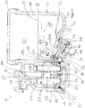
- FIG. 1 a first embodiment of an oil pan filter combination 10 of an engine oil circuit of an internal combustion engine of a motor vehicle is shown in a section.
- the oil pan-filter combination 10 comprises an oil pan 12 in which Figure 1 right, and an oil filter 14, in the Figure 1 Left.
- the oil pan 12 has an oil pan housing 16 with a peripheral wall 18 and a pan bottom 20 connected to it in one piece.
- a filter housing 22 of the oil filter 14 is integrally connected on a peripheral side to the peripheral wall 18 of the oil pan housing 16. The filter housing 22 is therefore integrated with the oil pan housing 16.
- the peripheral wall 18 On its upper edge opposite the pan bottom 20, the peripheral wall 18 has an oil pan flange 24 for attachment to an engine block (not shown) of the internal combustion engine.
- Oil is received in a pan interior 25 of the oil pan 12 and runs back into the oil pan 12 from the lubrication points and cooling points of the internal combustion engine.
- An oil sump 26 extends as far as an oil level 28.
- the pressure from the crankcase of the internal combustion engine prevails in the oil pan 12, which pressure almost corresponds to the ambient pressure in the case of an internal combustion engine that is shut down for an oil change, for example.
- the tub interior 25 can therefore be referred to as a "pressureless space".
- the operational state shown of the oil pan-filter combination 10 is closed with an oil drain screw 32.
- the oil drain opening 30 and the oil drain screw 32 are coaxial with an imaginary axis 34. They are parts of a drain device designated as a whole by 36.
- the axis 34 extends downwards at an angle to the spatial horizontal as viewed from the pan interior 25.
- the tub bottom 20 has a corresponding bulge in which the oil drain opening 30 is located.
- the oil drain screw 32 has an external thread which cooperates with a corresponding internal thread of an oil drain sealing section 40 on the side of the oil drain opening 30 as a screw connection.
- the closed state of the oil drain plug 32 shown is the oil pan closure section 38 and the oil pan sealing section 40 abut one another within the oil drain sealing area 42 and close the oil drain opening 30.
- An extension of the oil drain sealing area 42 axially to the axis 34 is provided with a reference number 44.
- oil drain screw 32 has an O-ring seal 46 in a circumferential sealing groove, which seals against a corresponding circumferential sealing surface on the side of the tub bottom 20.
- the peripheral wall 18 of the oil pan housing 16 has a housing passage 48 on its side facing the filter housing 22, which is part of the drainage device 36 and connects the tub interior 25 to a housing interior 50 of the filter housing 22.
- a sealing section 52 of the housing passage 48 on the side facing the oil drain opening 30 is coaxial with the axis 34.
- a largest diameter of the sealing section 52 is smaller than a smallest diameter of the oil drain opening 30, so that the oil drain plug 32 can be easily installed through the oil drain opening 30.
- the oil drain plug 32 has a closure section 54 which is coaxial with its longitudinal axis.
- the longitudinal axis of the oil drain screw 32 coincides with the axis 34 in the installed state and therefore has in the Figure 1 the same reference number for the sake of clarity.
- the radially outer circumferential side of the closing section 54 rests within a housing sealing area 56 on the radially inner circumferential side of the sealing section 52 and thus closes the housing passage 48.
- An axial extension of the housing sealing area 56 with respect to the axis 34 is provided with the reference numeral 58 .
- the cross section of the oil drain plug 32 tapers towards its free end.
- a circumferential sealing groove, in which an O-ring seal 60 is located, is arranged within the closure section 54.
- a sealing effect is improved, so that even if there is a pressure difference between the interior of the housing 50 and the tub interior 25, as can usually be the case when the internal combustion engine is operating, no oil can pass through the housing passage 48.
- the axial extension 58 of the housing sealing area 56 is smaller than the axial extension 44 of the oil drain sealing area 42. In this way, when the oil drain screw 32 is unscrewed, the housing passage 48 is first opened, the oil drain opening 30 remaining closed. In this way, pressure equalization can take place between the housing interior 58 and the tub interior 25. Oil can flow through the housing passage 48. Only after the oil drain screw 32 has been completely unscrewed is the oil drain opening 30 released so that the oil can flow out of the tub interior 25. In the process, any oil still contained in the housing interior 50 can flow into the tub interior 25. In this way, the housing interior 50 can also be emptied at least to the level of the housing passage 48.
- An oil inlet 62 which is connected to an oil pump, not shown, of the engine oil circuit is arranged on an upper side of the filter housing 22.
- a crude oil channel 64 leads eccentrically from the oil inlet 62 into the housing interior 50.
- a pure oil channel 68 coaxial with a filter axis 66 is connected via an oil outlet 70 to a section of the engine oil circuit which leads to the lubrication points and the cooling points.
- the filter housing 22 On its underside, the filter housing 22 has an insertion opening 72, which is coaxial with the filter axis 66, for a filter element 74.
- a circumferential wall of the filter housing 22 in the area of the introduction opening 72 has an internal thread 76 which forms a screw connection with an external thread of a cylinder section 78 of a housing cover 80.
- the housing cover 80 closes the introduction opening 72.
- a sealing groove with an O-ring seal 82 is arranged between the external thread of the cylinder section 78 and a bottom section of the housing cover 80 on the radially outer circumferential side of the cylinder section 78.
- the O-ring seal 82 interacts with a corresponding sealing surface on the radially inner circumferential side of the circumferential wall of the filter housing 22 in the region of the introduction opening 72.
- the O-ring seal 82 seals against the environment.
- the housing cover 80 can be unscrewed downwards.
- the cylinder section 78 has a plurality of circumferentially distributed passage openings 84 which extend from the radially inside to the radially outside.
- the passage openings 84 open into an annular channel 86 which runs circumferentially radially outside the cylinder section 78 in the circumferential wall of the filter housing 22.
- the annular channel 86 is connected to the housing passage 48.
- the passage openings 84 thus connect an interior space in the interior of the cylinder section 78 of the housing cover 80 via the annular channel 86 to the housing passage 48.
- the filter element 74 is located in the housing interior 50 in the interior space delimited radially on the outside by the cylinder section 78 of the housing cover 80.
- the filter element 74 is a round filter element with a zigzag folded and circumferentially closed filter medium. Overall, the filter medium has a circular cylindrical shape. The filter element 74 is arranged overall coaxially to the filter axis 66. On the front sides, the filter medium can each with one in the Figure 1 for the sake of clarity because of the end body (not shown), for example an end plate, be tightly connected.
- a support body center tube 88 is arranged in an element interior of the filter element 74.
- the support body central tube 88 has a plurality of passage openings for the oil in its peripheral wall.
- the filter element 74 is placed on a corresponding housing-side cylinder section of the filter housing 22 that is coaxial with the filter axis 66.
- the clean oil duct 68 which is open towards the element interior, runs in the cylinder section.
- a bypass valve 90 in the form of a spring-loaded bypass valve is arranged in the element interior in the region of the end face of the filter element 74 facing the housing cover 80.
- the bypass valve 90 opens a connection opening between a clean side and an unfiltered side of the filter element 74.
- the clean side of the filter element 74 is located in the element interior bounded by the filter medium; its unfiltered side is located outside the filter element 74.
- the crude oil channel 64 is also like the passage openings 84, the annular channel 86 and the housing passage 48 are connected to the raw side.
- the crude oil flows through the oil inlet 62 and the crude oil duct 64 to the housing interior 50.
- the crude oil flows from the raw side of the filter element 74 from the radial outside to the radial inside through the filter medium and is filtered there.
- the filtered pure oil passes through the pure oil duct 68 and the oil outlet 70 into the oil line of the engine oil circuit and to the lubrication points and the cooling points of the internal combustion engine.
- a pressure generated by the oil pump prevails in the filter housing 22, which pressure is greater than the pressure in the tub interior 25. Therefore, the housing interior 50 can also be referred to as a “pressure space”.
- the oil drain screw 32 is first unscrewed from the oil drain opening 30 in the opening direction.
- the housing passage 48 is first opened.
- the housing interior 50 is connected to the tub interior 25 through the passage openings 84, the annular channel 86 and the housing passage 48.
- a pressure equalization can take place between the housing interior 50 and the tub interior 25. In this case, oil can flow through the opened housing passage 48.
- the engine oil can flow out of the tub interior 25. Any oil still contained in the housing interior 50 can flow through the housing passage 48 into the tub interior 25 and also flow away.
- the housing cover 80 is then screwed downward out of the insertion opening 72 of the filter housing 22.
- the filter element 74 is pulled out of the filter housing 22 axially to the filter axis 66 downwards.
- a new filter element is installed in the opposite direction.
- the housing cover 80 is screwed into the insertion opening 72 from below.
- the oil drain screw 32 is screwed completely into the oil drain opening 30 so that it tightly closes both the oil drain opening 30 and the housing passage 48. Fresh oil can then be filled into the engine oil circuit in a manner which is not of further interest here.
- FIG 2 a second embodiment of an oil pan filter combination 10 is shown.
- the housing cover 80 additionally has a securing recess 192 on the radially outer circumferential side of its cylinder section 78.
- the fuse recess 192 is in the correct locking position of the housing cover 80, which is in the Figure 2 is shown, coaxial with the axis 34, that is, also with the sealing section 52, with the oil drain opening 30 and with the longitudinal axis of the installed oil drain screw 32.
- the oil drain plug 32 additionally has a securing section 194 which is coaxial to its longitudinal axis and, in the installed state, also to the axis 34.
- the securing section 194 protrudes into the securing recess 192 of the housing cover 80. It thus secures the housing cover 80 against undesired or unintentional unscrewing of the housing cover 80 with the oil drain screw 32 installed.
- the oil drain screw 32 can only be screwed in completely when the housing cover 80 is in its correct installation position.
- the securing recess 192 and the securing section 194 thus serve with the oil drain screw 32 as an indicator for the correct installation position of the housing cover 80.
- an oil pan 12 and a drain device 36 of an oil pan / filter combination 10 the following modifications, among others, are possible:
- the invention is not limited to oil pan filter combinations 10 of internal combustion engines of motor vehicles. Rather, it can also be used outside of automotive engineering, for example in industrial engines.
- the filter housing 22 can, instead of being arranged in one piece with the oil pan housing 16, also be arranged as a separate component on the oil pan 20.
- the filter housing 22 can preferably be attached to the oil pan 20.
- the filter housing 22 can also be integrated inside the oil pan 20, for example as a separate volume, instead of on the outside.
- the filter element 74 can also be designed as an oval round filter element with an oval cross section.
- a conical round filter element can also be provided.
- the filter medium of the filter element 74 can also be flat and closed circumferentially.
- a different type of connection preferably rotatable and / or plug-in connection, for example a bayonet-type connection, can also be provided.
- the annular channel 86 can additionally or alternatively be connected to a collecting container (not shown) into which the oil can drain out of the filter housing 22 through the housing passage 48 when the oil drain screw 32 is at least partially removed.
Description
- Die Erfindung betrifft eine Ölwannen-Filterkombination insbesondere eines Motorölkreislaufs einer Brennkraftmaschine, insbesondere eines Kraftfahrzeugs, mit einer Ölwanne, einem an oder in der Ölwanne angeordneten Ölfilter, der ein öffenbares Filtergehäuse umfasst mit einem Gehäuseinnenraum, in dem ein Filterelement austauschbar angeordnet werden kann, wobei der Gehäuseinnenraum des Filtergehäuses mittels wenigstens einem Gehäusedurchlass mit einem Wanneninnenraum der Ölwanne verbunden ist, welcher mittels einer Gehäusedurchlassverschlusseinrichtung verschließbar ist.
- Aus der
EP 1 094 203 A1 ist eine Ölfiltervorrichtung für Brennkraftmaschinen mit einem an einer Ölwanne integral verbundenen, hängend angeordneten Ölfiltergehäuse mit einer geodätisch unteren Öffnung zum Ein- und Ausbau eines Filtereinsatzes bekannt. Der Öffnung des Ölfiltergehäuses ist ein in das Ölfiltergehäuse zum Öffnen und Verschließen einführbar ausgebildeter, topfförmiger Verschlussdeckel zugeordnet. Um bei einem Wechsel des Ölfiltereinsatzes eine Ableitung des im Ölfiltergehäuse enthaltenen Öles über die freie Umgebung in ein gesondertes Auffanggefäß zu vermeiden, ist vorgesehen, dass der Verschlussdeckel in Schließstellung mittels eines freien Topfabschnittes und einer Ringdichtung gegenüber einer stromab im Ölfiltergehäuse in die Ölwanne gerichtet angeordneten Ablauföffnung eine Ablaufsperre bildet. Die Ablaufsperre ist über eine Öffnungsdrehbewegung des Verschlussdeckels aufhebbar. - Aus
DE 200 12 736 U1 ist eine Baugruppe bekannt, die eine erste und eine zweite Gehäusestruktur aufweist. In der ersten Gehäusestruktur ist beispielsweise ein Ölfilter untergebracht, in der zweiten Gehäusestruktur ist zumindest eine Kanalstruktur untergebracht, die zur Durchleitung der im Ölkreislauf befindlichen Fluide geeignet ist. Der Ölablauf des Ölfilters und die Kanalstruktur, die in der zweiten Gehäusestruktur vorgesehen ist, münden ineinander, so dass ein gemeinsamer Leitungsabschnitt für die Kanalstrukturen entsteht. - Die
EP 2 236 779 B1 zeigt eine Ölwanne, die einen Behälter, der eine Ablassöffnung zum selektiven Ablassen von Fluid aus der Ölwanne definiert, eine Wand, die einen Filterhohlraum in Fluidverbindung mit einem Aufnahmedurchgang und einem Abgabedurchgang der Ölwanne definiert, umfasst, wobei der Aufnahmedurchgang eine Fluidverbindung von dem Behälter zu dem Filterhohlraum ermöglicht und der Abgabedurchgang eine Fluidverbindung von dem Filterhohlraum zu dem Behälter ermöglicht. - Der Erfindung liegt die Aufgabe zugrunde, eine Ölwannen-Filterkombination der eingangs benannten Art zu gestalten, bei der mit einem Verschlusselement sowohl der Gehäusedurchlass geöffnet als auch ein Ablassen des Öls aus der Ölwannen-Filterkombination ermöglicht werden kann.
- Diese Aufgabe wird erfindungsgemäß dadurch gelöst, dass die Ölwanne eine Ölablassöffnung aufweist, welche mit einem Verschlusselement verschließbar ist, wobei der wenigstens eine Gehäusedurchlass auf seiner der Ölablassöffnung zugewandten Seite einen Dichtabschnitt aufweist und das Verschlusselement an einem dem Gehäusedurchlass zugewandten Bereich einen zu dem Dichtabschnitt passenden Verschlussabschnitt aufweist, welcher zum Verschließen des Gehäusedurchlasses mit dem Dichtabschnitt schließend zusammenwirken kann.
- Erfindungsgemäß weist das Verschlusselement zwei Dichtstellen oder Verschlussstellen auf, an denen jeweils der Gehäusedurchlass und die Ölablassöffnung verschlossen werden kann. Bei einer Entfernung des Verschlusselements werden der Gehäusedurchlass und die Ölablassöffnung freigegeben. Auf diese Weise können mit nur einem Verschlusselement sowohl der Gehäusedurchlass als auch die Ölablassöffnung kontrolliert werden. So wird der Montageaufwand und der Bauteilaufwand reduziert. Bei einem Öl- und/oder Filterwechsel kann durch Entfernen des Verschlusselements das Öl aus einem Vorratsvolumen, insbesondere der Ölwanne, und einem zweiten Volumen, insbesondere dem Filtergehäuse, abgelassen werden. In den zwei Volumina können unterschiedliche Fluide gehalten werden. In der Ölwanne kann sich verunreinigtes Öl, sogenanntes Rohöl, befinden, das an den Schmierstellen vorbei zur geodätisch tiefsten Stelle zurückfließt und sich in der Ölwanne sammelt. Es kann in der Ölwanne annähernd der gleiche Druck herrschen wie in einem Kurbelgehäuse der Brennkraftmaschine. Das zweite Volumen kann durch das Filtergehäuse zumindest mit gebildet sein. Es kann, je nach Durchströmungsrichtung des Öls durch das Filterelement, mit gereinigtem Öl, sogenanntem Reinöl, das zuvor durch ein Filtermedium des Filterelements geflossen ist, gefüllt sein oder mit Rohöl, das sich im Filtergehäuse befindet, bevor das Öl durch das Filtermedium fließt, gefüllt sein.
- Während des Betriebes der Brennkraftmaschine kann im Filtergehäuse ein höherer Druck als in der Ölwanne herrschen. Im Ruhezustand der Brennkraftmaschine kann der Druck im Filtergehäuse ähnlich oder gleich wie der Druck in der Ölwanne sein. Der Innendruck von Filtergehäuse und Ölwanne kann gleich dem Umgebungsdruck außerhalb Brennkraftmaschine entsprechen. Die Ölwannen-Filterkombination befindet sich im sogenannten "drucklosen" Zustand.
- Im betriebsbereiten Zustand der Ölwannen-Filterkombination ist das Verschlusselement in seinen Schließzustand. Der Gehäusedurchlass ist mit dem Verschlussabschnitt des Verschlusselements verschlossen. Der Gehäuseinnenraum des Filtergehäuses ist von dem Wanneninnenraum der Ölwanne fluidtechnisch getrennt. Ein Ölablassdichtabschnitt des Verschlusselements verschließt die Ölablassöffnung und dichtet den Wanneninnenraum gegen die Umgebung ab.
- Vorteilhafterweise kann ein größter Durchmesser des Gehäusedurchlasses wenigstens im Dichtabschnitt kleiner sein als ein kleinster Durchmesser der Ölablassöffnung. Entsprechend kann auch ein größter Durchmesser des Verschlussabschnitts des Verschlusselements kleiner sein als ein kleinster Durchmesser eines zur Ölablassöffnung passender Ölablassverschlussabschnitts des Verschlusselements. Auf diese Weise kann das Verschlusselement einfach durch die Ölablassöffnung eingebracht werden.
- Erfindungsgemäß sind der Dichtabschnitt und die Ölablassöffnung zu einer gemeinsamen Achse koaxial. Das Verschlusselement kann so einfach auf geradem Weg in Richtung der Achse von außen durch die Ölablassöffnung an den Gehäusedurchlass, insbesondere den Dichtabschnitt, eingebracht werden. Das Verschlusselement kann vorteilhafterweise einfach mittels einer Dreh- und/oder Steckbewegung bezüglich der gemeinsamen Achse eingeführt und entfernt werden.
- Erfindungsgemäß ist eine bezüglich der gemeinsamen Achse axiale Ausdehnung eines Gehäusedichtbereichs, in dem im Schließzustand des Verschlusselements der Verschlussabschnitt dicht an dem Dichtabschnitt des Gehäusedurchlasses anliegt, kleiner als eine axiale Ausdehnung eines Ölablassdichtbereichs, in dem im Schließzustand ein Ölablassverschlussabschnitt des Verschlusselements dicht an einem Ölablassdichtabschnitt der Ölablassöffnung anliegt. Auf diese Weise wird bei einem Entfernen des Verschlusselements zunächst der Dichtabschnitt des Gehäusedurchlasses freigegeben, ohne dass die Ölablassöffnung freigegeben wird. Das Öl kann, je nach Druckverhältnissen und/oder Ölfüllständen in den beiden Volumina, durch den Gehäusedurchlass aus dem Gehäuseinnenraum in den Wanneninnenraum oder umgekehrt fließen. Es kann ein Druckausgleich zwischen dem Gehäuseinnenraum und dem Wanneninnenraum stattfinden. Durch eine weitere Öffnungsbewegung axial zur gemeinsamen Achse kann das Verschlusselement die Ölablassöffnung freigeben. Vorteilhafterweise kann das Verschlusselement vollständig aus der Ablassöffnung entfernt werden. Das in dem Wanneninnenraum enthaltene Öl kann durch die Ölablassöffnung ablaufen. Etwa im Gehäuseinnenraum noch enthaltenes Öl kann durch den Gehäusedurchlass in den Wanneninnenraum nachströmen. Insgesamt können so der Gehäusedurchlass und die Ölablassöffnung stufenweise durch kontinuierliche oder schrittweise Entfernung des Verschlusselements freigegeben werden.
- Bei einer weiteren vorteilhaften Ausführungsform kann die gemeinsame Achse in der üblichen Einbaulage der Ölwannen-Filterkombination vom Gehäusedurchlass aus in Richtung zur Ölablassöffnung betrachtet schräg nach unten verlaufen. Auf diese Weise kann der Dichtabschnitt des Gehäusedurchlasses räumlich oberhalb der Ölablassöffnung angeordnet werden. So kann ein Gefälle des Gehäusedurchlasses zwischen dem Gehäuseinnenraum des Filtergehäuses und dem Wanneninnenraum der Ölwanne realisiert werden. Das in dem Gehäuseinnenraum enthaltene Öl kann so einfacher und besser in den Wanneninnenraum abfließen. Außerdem kann die Ölablassöffnung insgesamt räumlich tiefer in der Ölwanne angeordnet werden. Das Verschlusselement kann von schräg unten in die Ölablassöffnung eingebracht werden. Alternativ kann die gemeinsame Achse auch horizontal oder vertikal angeordnet verlaufen.
- Bei einer weiteren vorteilhaften Ausführungsform kann das Filtergehäuse eine Einbringöffnung für das Filterelement aufweisen, welche mit einem Gehäusedeckel verschließbar sein kann, und der Gehäusedeckel kann wenigstens eine Sicherungsvertiefung aufweisen, und das Verschlusselement kann einen Sicherungsabschnitt aufweisen, welcher in der korrekten Einbaulage des Gehäusedeckels im Schließzustand des Verschlusselements in die wenigstens eine Sicherungsvertiefung eingreifen kann. Auf diese Weise kann der Gehäusedeckel in der korrekten Einbaulage mit dem Verschlusselement gesichert werden. So kann verhindert werden, dass der Gehäusedeckel von dem Filtergehäuse getrennt werden kann, ohne dass das Verschlusselement zumindest teilweise entfernt wurde. Vorteilhafterweise kann eine axiale Ausdehnung des Sicherheitsabschnitts in Richtung der gemeinsamen Achse größer sein als eine axiale Ausdehnung des Gehäusedichtbereichs. Auf diese Weise kann beim Entfernen des Verschlusselements der Gehäusedurchlass freigegeben werden, bevor die Sicherung des Gehäusedeckels freigegeben wird.
- Vorteilhafterweise kann der Gehäusedeckel mittels einer Dreh- und/oder Steckbewegung in die oder auf der Einbringöffnung angeordnet und entfernt werden.
- Vorteilhafterweise kann die Sicherungsvertiefung in der korrekten Einbaulage des Gehäusedeckels koaxial zu der gemeinsamen Achse des Dichtabschnitts des Gehäusedurchlasses und der Ölablassöffnung angeordnet sein. Vorteilhafterweise kann der Sicherungsabschnitt an dem freien Ende des Verschlusselements angeordnet sein.
- Vorteilhafterweise kann der Gehäusedeckel wenigstens einen Fluidkanal aufweisen, welcher den Gehäuseinnenraum mit dem Gehäusedurchlass verbindet oder den Gehäusedurchlass mit bildet. Bei dem Fluidkanal kann es sich um wenigstens eine bezüglich einer Dreh- und/oder Steckachse des Gehäusedeckels von radial innen nach radial außen verlaufende Durchlassöffnung handeln. Die wenigstens eine Durchlassöffnung kann vorteilhafterweise in einen Ringraum münden. Der Ringraum kann sich umfangsmäßig bezüglich der Dreh- und/oder Steckachse des Gehäusedeckels an der radial äußeren Umfangsseite des Gehäusedeckels erstrecken. Der Ringraum kann bei korrekter Einbaulage des Gehäusedeckels mit dem wenigstens einen Gehäusedurchlass beziehungsweise einem Abschnitt des Gehäusedurchlasses im Gehäusegrundkörper verbunden sein.
- Bei einer weiteren vorteilhaften Ausführungsform kann das Verschlusselement ein Außengewinde aufweisen, welches mit einem entsprechenden Innengewinde im Bereich der Ölablassöffnung verschraubt werden kann. Mittels einer Schraubverbindung kann das Verschlusselement stabil und präzise in die Ölablassöffnung eingeschraubt werden. So kann der Dichtabschnitt beim Herausschrauben des Verschlusselements des Gehäusedurchlasses präzise und kontinuierlich freigegeben werden. Eine Belastung einer etwa zwischen dem Dichtabschnitt und dem Verschlussabschnitt angeordneten Dichtung, insbesondere einer O-Ring-Dichtung, beim Schließen und Öffnen des Verschlusselements kann durch die Schraubbewegung verringert werden. Ferner kann so ein etwa stufenweises Öffnen des Gehäusedurchlasses und der Ölablassöffnung vereinfacht und verbessert werden.
- Bei einer weiteren vorteilhaften Ausführungsform kann zwischen dem Verschlussabschnitt des Verschlusselements und dem Dichtabschnitt des Gehäusedurchlasses eine Dichtung, insbesondere eine O-Ring-Dichtung, angeordnet sein. Mittels der Dichtung kann eine Dichtheit des verschlossenen Gehäusedurchlasses verbessert werden. So kann auch bei eventuellen Druckunterschieden zwischen den mit dem Gehäusedurchlass verbundenen Volumina ein Fluidfluss, insbesondere ein Ölfluss, durch den geschlossenen Gehäusedurchlass verhindert werden. Vorteilhafterweise kann die Dichtung an dem Verschlusselement angeordnet sein. So kann sie gemeinsam mit dem Verschlusselement in die Ölablassöffnung eingebracht werden. Vorteilhafterweise kann das Verschlusselement eine entsprechende Dichtungsnut zur Aufnahme der Dichtung aufweisen.
- Bei einer weiteren vorteilhaften Ausführungsform kann sich ein Querschnitt des Verschlussabschnitts zu dem freien Ende des Verschlusselements hin verjüngen, insbesondere kann der Verschlussabschnitt konisch zulaufen. So kann erreicht werden, dass beim Entfernen des Verschlusselements ein Öffnungsspalt zwischen dem Verschlussabschnitt und dem Dichtabschnitt des Gehäusedurchlasses gleichmäßiger vergrößert werden kann. Vorteilhafterweise kann sich entsprechend ein Querschnitt des Dichtabschnitts zum Gehäuseinnenraum hin verjüngen. Die Konturen des Verschlussabschnitts und des Dichtungsabschnitts können vorteilhafterweise aneinander angepasst sein. Auf diese Weise kann der Verschlussabschnitt in der Schließstellung des Verschlusselements flächig an dem Dichtabschnitt anliegen. So kann eine Dichtfunktion verbessert werden. Die Konturen des Verschlussabschnitts und des Dichtabschnitts können so optimiert sein, dass auf eine separate Dichtung kann verzichtet werden kann.
- Bei einer weiteren vorteilhaften Ausführungsform kann das Filtergehäuse außerhalb der Ölwanne angeordnet sein. Auf diese Weise kann das Filtergehäuse von außen gut zugänglich sein. Ferner kann eine Trennung, insbesondere eine Abdichtung, des Druckraums im Gehäuseinnenraum gegenüber dem drucklosen Raum im Wanneninnenraum vereinfacht werden. Vorteilhafterweise kann das Filtergehäuse einstückig mit einem Ölwannengehäuse der Ölwanne verbunden sein. Auf diese Weise können die Ölwanne und das Filtergehäuse, insbesondere der Gehäusegrundkörper, einfach gemeinsam hergestellt werden.
- Weitere Vorteile, Merkmale und Einzelheiten der Erfindung ergeben sich aus der nachfolgenden Beschreibung, in der Ausführungsbeispiele der Erfindung anhand der Zeichnung näher erläutert werden. Der Fachmann wird die in der Zeichnung, der Beschreibung und den Ansprüchen in Kombination offenbarten Merkmale zweckmäßigerweise auch einzeln betrachten und zu sinnvollen weiteren Kombinationen zusammenfassen. Es zeigen schematisch
- Figur 1
- einen Schnitt einer Ölwannen-Filterkombination eines Motorölkreislaufs einer Brennkraftmaschine gemäß einem ersten Ausführungsbeispiel;
- Figur 2
- einen Schnitt einer Ölwannen-Filterkombination gemäß einem zweiten Ausführungsbeispiel, welche ähnlich ist zu der Ölwannen-Filterkombination aus
Figur 1 . - In den Figuren sind gleiche Bauteile mit gleichen Bezugszeichen versehen.
- In der
Figur 1 ist ein erstes Ausführungsbeispiel einer Ölwannen-Filterkombination 10 eines Motorölkreislaufs einer Brennkraftmaschine eines Kraftfahrzeugs in einem Schnitt gezeigt. - Die Ölwannen-Filterkombination 10 umfasst eine Ölwanne 12, in der
Figur 1 rechts, und einen Ölfilter 14, in derFigur 1 links. Die Ölwanne 12 weist ein Ölwannengehäuse 16 mit einer Umfangswand 18 und einem mit dieser einstückig verbundenen Wannenboden 20 auf. Ein Filtergehäuse 22 des Ölfilters 14 ist an einer Umfangsseite einstückig mit der Umfangswand 18 des Ölwannengehäuses 16 verbunden. Das Filtergehäuse 22 ist also mit dem Ölwannengehäuse 16 integriert. - An ihrem dem Wannenboden 20 gegenüberliegenden oberen Rand weist die Umfangswand 18 einen Ölwannenflansch 24 zur Befestigung an einem nicht gezeigten Motorblock der Brennkraftmaschine auf.
- In einem Wanneninnenraum 25 der Ölwanne 12 ist Öl aufgenommen, das von Schmierstellen und Kühlstellen der Brennkraftmaschine zurück in die Ölwanne 12 läuft. Ein Ölsumpf 26 reicht bis zu einem Ölspiegel 28. In der Ölwanne 12 herrscht der Druck aus dem Kurbelgehäuse der Brennkraftmaschine, der im Falle einer beispielsweise zum Ölwechsel abgestellten Brennkraftmaschine nahezu dem Umgebungsdruck entspricht. Der Wanneninnenraum 25 kann daher als "druckloser Raum" bezeichnet werden.
- An der geodätisch tiefsten Stelle der Ölwanne 12 befindet sich im Wannenboden 20 eine Ölablassöffnung 30, welche in dem in der
Figur 1 gezeigten betriebsbereiten Zustand der Ölwannen-Filterkombination 10 mit einer Ölablassschraube 32 verschlossen ist. Die Ölablassöffnung 30 und die Ölablassschraube 32 sind koaxial zu einer gedachten Achse 34. Sie sind Teile einer insgesamt mit 36 bezeichneten Ablassvorrichtung. Die Achse 34 erstreckt sich in der normalen Einbaulage der Ölwannen-Filterkombination 10 schräg zur räumlichen Horizontalen von dem Wanneninnenraum 25 aus betrachtet nach unten. Der Wannenboden 20 weist eine entsprechende Ausbuchtung auf, in der sich die Ölablassöffnung 30 befindet. - In einem Ölablassverschlussabschnitt 38 weist die Ölablassschraube 32 ein Außengewinde auf, welches mit einem entsprechenden Innengewinde eines Ölablassdichtabschnitts 40 auf Seiten der Ölablassöffnung 30 als Schraubverbindung zusammenwirkt. In dem in der
Figur 1 gezeigten Schließzustand der Ölablassschraube 32 liegen der Ölwannenverschlussabschnitt 38 und der Ölwannendichtabschnitt 40 innerhalb des Ölablassdichtbereichs 42 aneinander an und verschließen die Ölablassöffnung 30. Eine Ausdehnung des Ölablassdichtbereichs 42 axial zur Achse 34 ist mit einem Bezugszeichen 44 versehen. - Außerdem weist die Ölablassschraube 32 in einer umfangsmäßigen Dichtungsnut eine O-Ring-Dichtung 46, welche gegen eine entsprechende umfangsmäßige Dichtfläche auf Seiten des Wannenbodens 20 abdichtet.
- Die Umfangswand 18 des Ölwannengehäuses 16 weist auf ihrer dem Filtergehäuse 22 zugewandten Seite einen Gehäusedurchlass 48 auf, welcher Teil der Ablassvorrichtung 36 ist und den Wanneninnenraum 25 mit einem Gehäuseinnenraum 50 des Filtergehäuses 22 verbindet.
- Ein Dichtabschnitt 52 des Gehäusedurchlasses 48 auf der der Ölablassöffnung 30 zugewandten Seite ist koaxial zur Achse 34. Ein größter Durchmesser des Dichtabschnitts 52 ist kleiner als ein kleinster Durchmesser der Ölablassöffnung 30, sodass die Ölablassschraube 32 einfach durch die Ölablassöffnung 30 eingebaut werden kann.
- Die Ölablassschraube 32 weist an ihrem freien Ende einen zu ihrer Längsachse koaxialen Verschlussabschnitt 54 auf. Die Längsachse der Ölablassschraube 32 fällt in eingebauten Zustand mit der Achse 34 zusammen und hat daher in der
Figur 1 der besseren Übersichtlichkeit wegen dasselbe Bezugszeichen. In dem Schließzustand der Ölablassschraube 32 liegt die radial äußere Umfangsseite des Verschlussabschnitts 54 innerhalb eines Gehäusedichtbereichs 56 an der radial inneren Umfangsseite des Dichtabschnitts 52 an und verschließt so den Gehäusedurchlass 48. Eine bezüglich der Achse 34 axiale Ausdehnung des Gehäusedichtbereichs 56 ist mit dem Bezugszeichen 58 versehen. Axial zur Achse 34 betrachtet hinter dem Verschlussabschnitt 54 verjüngt sich der Querschnitt der Ölablassschraube 32 zu deren freien Ende hin. - Innerhalb des Verschlussabschnitts 54 ist eine umfangsmäßige Dichtungsnut angeordnet, in der sich eine O-Ring-Dichtung 60 befindet. Mit der O-Ring-Dichtung 60 wird eine Dichtwirkung verbessert, sodass auch bei einem Druckunterschied zwischen dem Gehäuseinnenraum 50 und dem Wanneninnenraum 25, wie dies beim Betrieb der Brennkraftmaschine in der Regel der Fall sein kann, kein Öl durch den Gehäusedurchlass 48 gelangen kann.
- Die axiale Ausdehnung 58 des Gehäusedichtbereichs 56 ist kleiner als die axiale Ausdehnung 44 des Ölablassdichtbereichs 42. Auf diese Weise wird beim Herausdrehen der Ölablassschraube 32 zunächst der Gehäusedurchlass 48 freigegeben, wobei die Ölablassöffnung 30 weiterhin verschlossen bleibt. So kann ein Druckausgleich zwischen dem Gehäuseinnenraum 58 und dem Wanneninnenraum 25 stattfinden. Es kann dabei Öl durch den Gehäusedurchlass 48 fließen. Erst nach vollständigem Herausschrauben der Ölablassschraube 32 wird auch die Ölablassöffnung 30 freigegeben, sodass das Öl aus dem Wanneninnenraum 25 abfließen kann. Dabei kann im Gehäuseinnenraum 50 etwa noch enthaltenes Öl in den Wanneninnenraum 25 nachfließen. So kann auch der Gehäuseinnenraum 50 zumindest bis auf Höhe des Gehäusedurchlasses 48 entleert werden.
- An einer Oberseite des Filtergehäuses 22 ist ein Öleinlass 62 angeordnet, welcher mit einer nicht gezeigten Ölpumpe des Motorölkreislaufs verbunden ist. Von dem Öleinlass 62 führt ein Rohölkanal 64 exzentrisch in den Gehäuseinnenraum 50. Ein zu einer Filterachse 66 koaxialer Reinölkanal 68 wird über einen Ölauslass 70 mit einem Abschnitt des Motorölkreislaufs verbunden, welcher zu den Schmierstellen und den Kühlstellen führt.
- Das Filtergehäuse 22 weist an seiner Unterseite eine zur Filterachse 66 koaxiale Einbringöffnung 72 für ein Filterelement 74 auf. Eine Umfangswand des Filtergehäuses 22 im Bereich der Einbringöffnung 72 weist ein Innengewinde 76 auf, welches mit einem Außengewinde eines Zylinderabschnitts 78 eines Gehäusedeckels 80 eine Schraubverbindung eingeht. Der Gehäusedeckel 80 verschließt die Einbringöffnung 72.
- Zwischen dem Außengewinde des Zylinderabschnitts 78 und einem Bodenabschnitt des Gehäusedeckels 80 ist an der radial äußeren Umfangsseite des Zylinderabschnitts 78 eine Dichtungsnut mit einer O-Ring-Dichtung 82 angeordnet. Die O-Ring-Dichtung 82 wirkt mit einer entsprechenden Dichtfläche an der radial inneren Umfangsseite der Umfangswand des Filtergehäuses 22 im Bereich der Einbringöffnung 72 zusammen. Die O-Ring-Dichtung 82 dichtet gegen die Umgebung ab. Zum Zwecke des Wechsels des Filterelements 74 kann der Gehäusedeckel 80 nach unten herausgeschraubt werden.
- Zwischen der O-Ring-Dichtung 82 und dem Außengewinde weist der Zylinderabschnitt 78 eine Mehrzahl von umfangsmäßig verteilten Durchlassöffnungen 84 auf, die sich von radial innen nach radial außen erstrecken. Die Durchlassöffnungen 84 münden in einen Ringkanal 86, der radial außerhalb des Zylinderabschnitts 78 in der Umfangswand des Filtergehäuses 22 umfangsmäßig verläuft. Der Ringkanal 86 ist mit dem Gehäusedurchlass 48 verbunden. Die Durchlassöffnungen 84 verbinden also einen Innenraum im Inneren des Zylinderabschnitts 78 des Gehäusedeckels 80 über den Ringkanal 86 mit dem Gehäusedurchlass 48.
- Das Filterelement 74 befindet sich im Gehäuseinnenraum 50 in dem durch den Zylinderabschnitt 78 des Gehäusedeckels 80 radial außen begrenzten Innenraum.
- Bei dem Filterelement 74 handelt es sich um ein Rundfilterelement mit einem zickzackförmig gefalteten und umfangsmäßig geschlossenen Filtermedium. Das Filtermedium hat insgesamt eine kreiszylindrische Form. Das Filterelement 74 ist insgesamt koaxial zur Filterachse 66 angeordnet. An den Stirnseiten kann das Filtermedium jeweils mit einem in der
Figur 1 der besseren Übersichtlichkeit wegen nicht gezeigten Endkörper, beispielsweise einer Endscheibe, dicht verbunden sein. - In einem Elementinnenraum des Filterelements 74 ist ein Stützkörpermittelrohr 88 angeordnet. Das Stützkörpermittelrohr 88 weist in seiner Umfangswand eine Mehrzahl von Durchlassöffnungen für das Öl auf.
- An einer in der
Figur 1 oberen Stirnseite ist das Filterelement 74 auf einen entsprechenden gehäuseseitigen, zur Filterachse 66 koaxialen Zylinderabschnitt des Filtergehäuses 22 gesteckt. In dem Zylinderabschnitt verläuft der Reinölkanal 68, der zum Elementinnenraum hin offen ist. - In dem Elementinnenraum ist im Bereich der dem Gehäusedeckel 80 zugewandten Stirnseite des Filterelements 74 ein Umgehungsventil 90 in Form eines federbelasteten Bypass-Ventils angeordnet. Im Fall einer unzulässigen Druckdifferenz öffnet das Umgehungsventil 90 eine Verbindungsöffnung zwischen einer Reinseite und einer Rohseite des Filterelements 74. Die Reinseite des Filterelements 74 befindet sich in dem durch das Filtermedium begrenzten Elementinnenraum, seine Rohseite befindet sich außerhalb des Filterelements 74. Der Rohölkanal 64 ist ebenso wie die Durchlassöffnungen 84, der Ringkanal 86 und der Gehäusedurchlass 48 mit der Rohseite verbunden.
- Bei einem Betrieb der Brennkraftmaschine fließt das Rohöl durch den Öleinlass 62 und den Rohölkanal 64 dem Gehäuseinnenraum 50 zu. Das Rohöl strömt von der Rohseite des Filterelements 74 von radial außen nach radial innen durch das Filtermedium und wird dort gefiltert. Vom Elementinnenraum des Filterelements 74 gelangt das gefilterte Reinöl durch den Reinölkanal 68 und den Ölauslass 70 in die Ölleitung des Motorölkreislaufs und zu den Schmierstellen und den Kühlstellen der Brennkraftmaschine. Beim Betrieb der Brennkraftmaschine herrscht in dem Filtergehäuse 22 ein von der Ölpumpe erzeugter Druck, der größer ist als der Druck im Wanneninnenraum 25. Daher kann der Gehäuseinnenraum 50 auch als "Druckraum" bezeichnet werden.
- Bei Wartungsarbeiten, beispielsweise zu einem Ölwechsel und/oder einem Filterwechsel, wird beim Stillstand der Brennkraftmaschine zunächst die Ölablassschraube 32 in Öffnungsrichtung aus der Ölablassöffnung 30 herausgeschraubt. In einer ersten Öffnungsstufe der Ablassvorrichtung 36 wird aufgrund der axial kürzeren Ausdehnung 58 des Gehäusedichtbereichs 56 zunächst der Gehäusedurchlass 48 freigegeben. Der Gehäuseinnenraum 50 wird durch die Durchlassöffnungen 84, den Ringkanal 86 und den Gehäusedurchlass 48 mit dem Wanneninnenraum 25 verbunden. Es kann ein Druckausgleich zwischen dem Gehäuseinnenraum 50 und dem Wanneninnenraum 25 stattfinden. Dabei kann Öl durch den geöffneten Gehäusedurchlass 48 strömen.
- Nachdem die Ölablassschraube 32 vollständig aus der Ölablassöffnung 30 entfernt wurde, kann das Motoröl aus dem Wanneninnenraum 25 abfließen. Im Gehäuseinnenraum 50 etwa noch enthaltenes Öl kann dabei durch den Gehäusedurchlass 48 in den Wanneninnenraum 25 nachfließen und ebenfalls abfließen.
- Anschließend wird der Gehäusedeckel 80 nach unten aus der Einbringöffnung 72 des Filtergehäuses 22 herausgeschraubt. Das Filterelement 74 wird axial zur Filterachse 66 nach unten aus dem Filtergehäuse 22 herausgezogen.
- Ein neues Filterelement wird in umgekehrter Richtung eingebaut. Der Gehäusedeckel 80 wird von unten in die Einbringöffnung 72 eingeschraubt. Die Ölablassschraube 32 wird vollständig in die Ölablassöffnung 30 eingeschraubt, sodass sie sowohl die Ölablassöffnung 30 als auch den Gehäusedurchlass 48 dicht verschließt. Anschließend kann in hier nicht weiter interessierender Weise frisches Öl in den Motorölkreislauf gefüllt werden.
- In
Figur 2 ist ein zweites Ausführungsbeispiel einer Ölwannen-Filterkombination 10 gezeigt. Diejenigen Elemente die zu denen des ersten Ausführungsbeispiel aus derFigur 1 ähnlich sind, sind mit denselben Bezugszeichen versehen. Das zweite Ausführungsbeispiel unterscheidet sich von dem ersten Ausführungsbeispiel dadurch, dass der Gehäusedeckel 80 zusätzlich an der radial äußeren Umfangsseite seines Zylinderabschnitts 78 eine Sicherungsvertiefung 192 aufweist. Die Sicherungsvertiefung 192 ist in der korrekten Verschlusslage des Gehäusedeckels 80, die in derFigur 2 gezeigt ist, koaxial zur Achse 34, also auch zum Dichtabschnitt 52, zur Ölablassöffnung 30 und zur Längsachse der eingebauten Ölablassschraube 32. - Die Ölablassschraube 32 weist an ihrem freien Ende zusätzlich einen Sicherungsabschnitt 194 auf, welcher zu ihrer Längsachse und im eingebauten Zustand auch zur Achse 34 koaxial ist. In dem in der
Figur 2 gezeigten Schließzustand der Ablassschraube 32 ragt der Sicherungsabschnitt 194 in die Sicherungsvertiefung 192 des Gehäusedeckels 80. Er sichert so den Gehäusedeckel 80 bei eingebauter Ölablassschraube 32 gegen unerwünschtes oder ungewolltes Herausschrauben des Gehäusedeckels 80. - Die Ölablassschraube 32 kann nur dann vollständig eingeschraubt werden, wenn sich der Gehäusedeckel 80 in seiner korrekten Einbaulage befindet. Die Sicherungsvertiefung 192 und der Sicherungsabschnitt 194 dienen so mit der Ölablassschraube 32 als Indikator für die korrekte Einbaulage des Gehäusedeckels 80.
- Bei allen oben beschriebenen Ausführungsbeispielen einer Ölwannen-Filterkombination 10, einer Ölwanne 12 und einer Ablassvorrichtung 36 einer Ölwannen-Filterkombination 10 sind unter anderem folgende Modifikationen möglich:
Die Erfindung ist nicht beschränkt auf Ölwannen-Filterkombinationen 10 von Brennkraftmaschinen von Kraftfahrzeugen. Vielmehr kann sie auch außerhalb der Kraftfahrzeugtechnik, beispielsweise bei Industriemotoren, eingesetzt werden. - Das Filtergehäuse 22 kann statt einstückig mit dem Ölwannengehäuse 16 auch als separates Bauteil an der Ölwanne 20 angeordnet sein. Bevorzugt kann das Filtergehäuse 22 an der Ölwanne 20 befestigt sein. Das Filtergehäuse 22 kann statt außen auch innerhalb der Ölwanne 20, beispielsweise als separates Volumen, integriert sein.
- Das Filterelement 74 kann auch als ovales Rundfilterelement mit einem ovalen Querschnitt ausgestaltet sein. Es kann auch ein konisches Rundfilterelement vorgesehen sein.
- Das Filtermedium des Filterelements 74 kann statt zickzackförmig gefaltet auch eben und umfangsmäßig geschlossen sein.
- Statt einer Schraubverbindung oder einem Gewindeverschluss zwischen dem Gehäusedeckel 80 und dem Filtergehäuse 22 kann auch eine andersartige, bevorzugt dreh- und/oder steckbare Verbindung, beispielsweise eine bajonettartige Verbindung, vorgesehen sein.
- Der Ringkanal 86 kann zusätzlich oder alternativ mit einem nicht dargestellten Auffangbehälter verbunden sein, in den bei zumindest teilweise entfernter Ölablassschraube 32 das Öl durch den Gehäusedurchlass 48 aus dem Filtergehäuse 22 ablaufen kann.
- Bei dem Ölfilter 14 ist auch eine umgekehrte Strömungsführung möglich, bei der das Öl von radial innen nach radial außen durch das Filtermedium strömen kann. Die Funktionen des Öleinlasses 62 und des Ölauslasses 70 sind in diesem Fall vertauscht. Der Verschlussabschnitt 54 dichtet in dieser Anordnung den Reinölbereich des Ölfilters 14 gegen das Öl im Ölsumpf 26 der Ölwanne 12 ab.
Claims (7)
- Ölwannen-Filterkombination (10) insbesondere eines Motorölkreislaufs einer Brennkraftmaschine, insbesondere eines Kraftfahrzeugs, mit einer Ölwanne (12), einem an oder in der Ölwanne (12) angeordneten Ölfilter (14), der ein öffenbares Filtergehäuse (22) umfasst mit einem Gehäuseinnenraum (50), in dem ein Filterelement (74) austauschbar angeordnet werden kann, wobei der Gehäuseinnenraum (50) des Filtergehäuses (22) mittels wenigstens einem Gehäusedurchlass (48) mit einem Wanneninnenraum (25) der Ölwanne (12) verbunden ist, welcher mittels einer Gehäusedurchlassverschlusseinrichtung (32, 52, 54, 60) verschließbar ist, wobei die Ölwanne (12) eine Ölablassöffnung (30) aufweist, welche mit einem Verschlusselement (32) verschließbar ist, wobei der wenigstens eine Gehäusedurchlass (48) auf seiner der Ölablassöffnung (30) zugewandten Seite einen Dichtabschnitt (52) aufweist und das Verschlusselement (32) an einem dem Gehäusedurchlass (48) zugewandten Bereich einen zu dem Dichtabschnitt (52) passenden Verschlussabschnitt (54) aufweist, welcher zum Verschließen des Gehäusedurchlasses (48) mit dem Dichtabschnitt (52) schließend zusammenwirken kann, dadurch gekennzeichnet, dass der Dichtabschnitt (52) und die Ölablassöffnung (30) zu einer gemeinsamen Achse (34) koaxial sind, wobei eine bezüglich der gemeinsamen Achse (34) axiale Ausdehnung (58) eines Gehäusedichtbereichs (56), in dem im Schließ-zustand des Verschlusselements (32) der Verschlussabschnitt (54) dicht an dem Dichtabschnitt (52) des Gehäusedurchlasses (48) anliegt, kleiner ist als eine axiale Ausdehnung (44) eines Ölablassdichtbereichs (42), in dem im Schließzustand ein Ölablassverschlussabschnitt (38) des Verschlusselements (32) dicht an einem Ölablassdichtabschnitt (40) der Ölablassöffnung (30) anliegt.
- Ölwannen-Filterkombination nach Anspruch 1, dadurch gekennzeichnet, dass die gemeinsame Achse (34) in der üblichen Einbaulage der Ölwannen-Filterkombination (10) vom Gehäusedurchlass (48) aus in Richtung zur Ölablassöffnung (30) betrachtet schräg nach unten verläuft.
- Ölwannen-Filterkombination nach einem der vorigen Ansprüche, dadurch gekennzeichnet, dass das Filtergehäuse (22) eine Einbringöffnung (72) für das Filterelement (74) aufweist, welche mit einem Gehäusedeckel (80) verschließbar ist, und der Gehäusedeckel (80) wenigstens eine Sicherungsvertiefung (192) aufweist, und das Verschlusselement (32) einen Sicherungsabschnitt (194) aufweist, welcher in der korrekten Einbaulage des Gehäusedeckels (80) im Schließzustand des Verschlusselements (32) in die wenigstens eine Sicherungsvertiefung (192) eingreifen kann.
- Ölwannen-Filterkombination nach einem der vorigen Ansprüche, dadurch gekennzeichnet, dass das Verschlusselement (32) ein Außengewinde aufweist, welches mit einem entsprechenden Innengewinde im Bereich der Ölablassöffnung (30) verschraubt werden kann.
- Ölwannen-Filterkombination nach einem der vorigen Ansprüche, dadurch gekennzeichnet, dass zwischen dem Verschlussabschnitt (54) des Verschlusselements (32) und dem Dichtabschnitt (52) des Gehäusedurchlasses (48) eine Dichtung, insbesondere eine O-Ring-Dichtung (46), angeordnet ist.
- Ölwannen-Filterkombination nach einem der vorigen Ansprüche, dadurch gekennzeichnet, dass sich ein Querschnitt des Verschlussabschnitts (54) zu dem freien Ende des Verschlusselements (32) hin verjüngt, insbesondere der Verschlussabschnitt (54) konisch zuläuft.
- Ölwannen-Filterkombination nach einem der vorigen Ansprüche, dadurch gekennzeichnet, dass das Filtergehäuse (22) außerhalb der Ölwanne (12) angeordnet ist.
Applications Claiming Priority (2)
| Application Number | Priority Date | Filing Date | Title |
|---|---|---|---|
| DE102012022989 | 2012-11-26 | ||
| PCT/EP2013/053694 WO2014079591A1 (de) | 2012-11-26 | 2013-02-25 | Ölwannen-filterkombination, ölwanne und ablassvorrichtung einer ölwannen-filterkombination |
Publications (2)
| Publication Number | Publication Date |
|---|---|
| EP2923045A1 EP2923045A1 (de) | 2015-09-30 |
| EP2923045B1 true EP2923045B1 (de) | 2021-04-14 |
Family
ID=47757590
Family Applications (1)
| Application Number | Title | Priority Date | Filing Date |
|---|---|---|---|
| EP13706966.2A Active EP2923045B1 (de) | 2012-11-26 | 2013-02-25 | Ölwannen-filterkombination, ölwanne und ablassvorrichtung einer ölwannen-filterkombination |
Country Status (2)
| Country | Link |
|---|---|
| EP (1) | EP2923045B1 (de) |
| WO (1) | WO2014079591A1 (de) |
Families Citing this family (4)
| Publication number | Priority date | Publication date | Assignee | Title |
|---|---|---|---|---|
| DE102014007816B4 (de) * | 2014-06-02 | 2017-12-28 | Mann + Hummel Gmbh | Ölwannen-Filtermodul mit wenigstens einem Wannenablass und wenigstens einem Filterablass, Verschlusseinheit eines Ölwannen-Filtermoduls und Baueinheit aus einer Verschlusseinheit und einem Ölfilterelement eines Ölwannen-Filtermoduls |
| DE102014015265A1 (de) | 2014-10-16 | 2016-04-21 | Daimler Ag | Schmierölversorgungseinrichtung für eine Verbrennungskraftmaschine sowie Filtereinsatz für eine solche Schmierölversorgungseinrichtung |
| JP6661984B2 (ja) * | 2015-11-12 | 2020-03-11 | いすゞ自動車株式会社 | オイルパン装置 |
| ES2913062T3 (es) | 2018-01-16 | 2022-05-31 | Volvo Truck Corp | Un sistema de aceite de motor y una tapa |
Family Cites Families (3)
| Publication number | Priority date | Publication date | Assignee | Title |
|---|---|---|---|---|
| DE19950888A1 (de) | 1999-10-22 | 2001-04-26 | Bayerische Motoren Werke Ag | Ölfiltervorrichtung für Brennkraftmaschinen |
| DE20012736U1 (de) * | 2000-07-22 | 2000-09-21 | Mann & Hummel Filter | Baugruppe für eine Brennkraftmaschine mit einem Ölfilter |
| US8272480B2 (en) * | 2009-03-12 | 2012-09-25 | Mahle International Gmbh | Oil pan integrated with filter and other components |
-
2013
- 2013-02-25 EP EP13706966.2A patent/EP2923045B1/de active Active
- 2013-02-25 WO PCT/EP2013/053694 patent/WO2014079591A1/de active Application Filing
Non-Patent Citations (1)
| Title |
|---|
| None * |
Also Published As
| Publication number | Publication date |
|---|---|
| WO2014079591A1 (de) | 2014-05-30 |
| EP2923045A1 (de) | 2015-09-30 |
Similar Documents
| Publication | Publication Date | Title |
|---|---|---|
| DE112013005747B4 (de) | Filter, Filterelement, Filtergehäuse und Ablassvorrichtung eines Filters | |
| EP3004620B1 (de) | Filterelement | |
| EP2670503B1 (de) | Filtersystem für motoröl einer brennkraftmaschine und wechselfilter eines filtersystems | |
| DE19716085B4 (de) | Filter, insbesondere für Kraftstoffe von Verbrennungsmotoren | |
| EP1174597B1 (de) | Baugruppe für eine Brennkraftmaschine mit einem Ölfilter | |
| EP1110590A2 (de) | Flüssigkeitsfilter mit Ablass für Flüssigkeitsrückstände | |
| EP1307274A1 (de) | Flüssigkeitsfilter | |
| DE102014010433A1 (de) | Filtrationsvorrichtung | |
| EP2923045B1 (de) | Ölwannen-filterkombination, ölwanne und ablassvorrichtung einer ölwannen-filterkombination | |
| EP2854986A1 (de) | Filtereinrichtung | |
| DE19961579A1 (de) | Flüssigkeitsfilter mit einem Kühler | |
| DE102006005108A1 (de) | Zylindrische Filtereinrichtung | |
| DE112014005458B4 (de) | Filterelement und Filtersystem mit Nebenstromfilterung | |
| WO2016058691A1 (de) | Filterelement für eine filtereinrichtung einer verbrennungskraftmaschine sowie filtereinrichtung für eine verbrennungskraftmaschine | |
| EP3033517B1 (de) | Flüssigkeitsfilter, insbesondere kraftstofffilter | |
| EP3352877B1 (de) | Filtervorrichtung mit pumpe | |
| WO2016008605A1 (de) | Ölfiltervorrichtung und gehäusedeckel und gehäusetopf einer ölfiltervorrichtung | |
| DE102014007302A1 (de) | Filtervorrichtung | |
| EP3691769A1 (de) | Filterelement mit entlüftungsfunktion für den hängenden anschluss an einem filterkopf sowie filtersystem | |
| DE202009001159U1 (de) | Ölabscheider | |
| DE3613093C2 (de) | ||
| DE112008003133B4 (de) | Ölfiltersystem eines Verbrennungsmotors | |
| WO2016008776A1 (de) | Hohlfilterelement eines filters für fluid, filter und filtergehäuse | |
| DE102019128397A1 (de) | Abscheidevorrichtung zur Abscheidung von Flüssigkeit aus Gas, insbesondere Luft, und Abscheidesystem einer Maschine | |
| DE102009006863A1 (de) | Ölabscheider |
Legal Events
| Date | Code | Title | Description |
|---|---|---|---|
| PUAI | Public reference made under article 153(3) epc to a published international application that has entered the european phase |
Free format text: ORIGINAL CODE: 0009012 |
|
| 17P | Request for examination filed |
Effective date: 20150414 |
|
| AK | Designated contracting states |
Kind code of ref document: A1 Designated state(s): AL AT BE BG CH CY CZ DE DK EE ES FI FR GB GR HR HU IE IS IT LI LT LU LV MC MK MT NL NO PL PT RO RS SE SI SK SM TR |
|
| AX | Request for extension of the european patent |
Extension state: BA ME |
|
| DAX | Request for extension of the european patent (deleted) | ||
| STAA | Information on the status of an ep patent application or granted ep patent |
Free format text: STATUS: EXAMINATION IS IN PROGRESS |
|
| 17Q | First examination report despatched |
Effective date: 20180718 |
|
| RAP1 | Party data changed (applicant data changed or rights of an application transferred) |
Owner name: MANN + HUMMEL GMBH |
|
| GRAP | Despatch of communication of intention to grant a patent |
Free format text: ORIGINAL CODE: EPIDOSNIGR1 |
|
| STAA | Information on the status of an ep patent application or granted ep patent |
Free format text: STATUS: GRANT OF PATENT IS INTENDED |
|
| INTG | Intention to grant announced |
Effective date: 20201120 |
|
| GRAS | Grant fee paid |
Free format text: ORIGINAL CODE: EPIDOSNIGR3 |
|
| GRAA | (expected) grant |
Free format text: ORIGINAL CODE: 0009210 |
|
| STAA | Information on the status of an ep patent application or granted ep patent |
Free format text: STATUS: THE PATENT HAS BEEN GRANTED |
|
| AK | Designated contracting states |
Kind code of ref document: B1 Designated state(s): AL AT BE BG CH CY CZ DE DK EE ES FI FR GB GR HR HU IE IS IT LI LT LU LV MC MK MT NL NO PL PT RO RS SE SI SK SM TR |
|
| REG | Reference to a national code |
Ref country code: GB Ref legal event code: FG4D Free format text: NOT ENGLISH |
|
| REG | Reference to a national code |
Ref country code: CH Ref legal event code: EP |
|
| REG | Reference to a national code |
Ref country code: DE Ref legal event code: R096 Ref document number: 502013015650 Country of ref document: DE |
|
| REG | Reference to a national code |
Ref country code: IE Ref legal event code: FG4D Free format text: LANGUAGE OF EP DOCUMENT: GERMAN |
|
| REG | Reference to a national code |
Ref country code: AT Ref legal event code: REF Ref document number: 1382561 Country of ref document: AT Kind code of ref document: T Effective date: 20210515 |
|
| RAP4 | Party data changed (patent owner data changed or rights of a patent transferred) |
Owner name: MANN+HUMMEL GMBH |
|
| REG | Reference to a national code |
Ref country code: LT Ref legal event code: MG9D |
|
| REG | Reference to a national code |
Ref country code: NL Ref legal event code: MP Effective date: 20210414 |
|
| PG25 | Lapsed in a contracting state [announced via postgrant information from national office to epo] |
Ref country code: FI Free format text: LAPSE BECAUSE OF FAILURE TO SUBMIT A TRANSLATION OF THE DESCRIPTION OR TO PAY THE FEE WITHIN THE PRESCRIBED TIME-LIMIT Effective date: 20210414 Ref country code: NL Free format text: LAPSE BECAUSE OF FAILURE TO SUBMIT A TRANSLATION OF THE DESCRIPTION OR TO PAY THE FEE WITHIN THE PRESCRIBED TIME-LIMIT Effective date: 20210414 Ref country code: LT Free format text: LAPSE BECAUSE OF FAILURE TO SUBMIT A TRANSLATION OF THE DESCRIPTION OR TO PAY THE FEE WITHIN THE PRESCRIBED TIME-LIMIT Effective date: 20210414 Ref country code: BG Free format text: LAPSE BECAUSE OF FAILURE TO SUBMIT A TRANSLATION OF THE DESCRIPTION OR TO PAY THE FEE WITHIN THE PRESCRIBED TIME-LIMIT Effective date: 20210714 Ref country code: HR Free format text: LAPSE BECAUSE OF FAILURE TO SUBMIT A TRANSLATION OF THE DESCRIPTION OR TO PAY THE FEE WITHIN THE PRESCRIBED TIME-LIMIT Effective date: 20210414 |
|
| PG25 | Lapsed in a contracting state [announced via postgrant information from national office to epo] |
Ref country code: ES Free format text: LAPSE BECAUSE OF FAILURE TO SUBMIT A TRANSLATION OF THE DESCRIPTION OR TO PAY THE FEE WITHIN THE PRESCRIBED TIME-LIMIT Effective date: 20210414 Ref country code: PL Free format text: LAPSE BECAUSE OF FAILURE TO SUBMIT A TRANSLATION OF THE DESCRIPTION OR TO PAY THE FEE WITHIN THE PRESCRIBED TIME-LIMIT Effective date: 20210414 Ref country code: NO Free format text: LAPSE BECAUSE OF FAILURE TO SUBMIT A TRANSLATION OF THE DESCRIPTION OR TO PAY THE FEE WITHIN THE PRESCRIBED TIME-LIMIT Effective date: 20210714 Ref country code: PT Free format text: LAPSE BECAUSE OF FAILURE TO SUBMIT A TRANSLATION OF THE DESCRIPTION OR TO PAY THE FEE WITHIN THE PRESCRIBED TIME-LIMIT Effective date: 20210816 Ref country code: LV Free format text: LAPSE BECAUSE OF FAILURE TO SUBMIT A TRANSLATION OF THE DESCRIPTION OR TO PAY THE FEE WITHIN THE PRESCRIBED TIME-LIMIT Effective date: 20210414 Ref country code: GR Free format text: LAPSE BECAUSE OF FAILURE TO SUBMIT A TRANSLATION OF THE DESCRIPTION OR TO PAY THE FEE WITHIN THE PRESCRIBED TIME-LIMIT Effective date: 20210715 Ref country code: IS Free format text: LAPSE BECAUSE OF FAILURE TO SUBMIT A TRANSLATION OF THE DESCRIPTION OR TO PAY THE FEE WITHIN THE PRESCRIBED TIME-LIMIT Effective date: 20210814 Ref country code: SE Free format text: LAPSE BECAUSE OF FAILURE TO SUBMIT A TRANSLATION OF THE DESCRIPTION OR TO PAY THE FEE WITHIN THE PRESCRIBED TIME-LIMIT Effective date: 20210414 Ref country code: RS Free format text: LAPSE BECAUSE OF FAILURE TO SUBMIT A TRANSLATION OF THE DESCRIPTION OR TO PAY THE FEE WITHIN THE PRESCRIBED TIME-LIMIT Effective date: 20210414 |
|
| REG | Reference to a national code |
Ref country code: DE Ref legal event code: R097 Ref document number: 502013015650 Country of ref document: DE |
|
| PG25 | Lapsed in a contracting state [announced via postgrant information from national office to epo] |
Ref country code: RO Free format text: LAPSE BECAUSE OF FAILURE TO SUBMIT A TRANSLATION OF THE DESCRIPTION OR TO PAY THE FEE WITHIN THE PRESCRIBED TIME-LIMIT Effective date: 20210414 Ref country code: EE Free format text: LAPSE BECAUSE OF FAILURE TO SUBMIT A TRANSLATION OF THE DESCRIPTION OR TO PAY THE FEE WITHIN THE PRESCRIBED TIME-LIMIT Effective date: 20210414 Ref country code: DK Free format text: LAPSE BECAUSE OF FAILURE TO SUBMIT A TRANSLATION OF THE DESCRIPTION OR TO PAY THE FEE WITHIN THE PRESCRIBED TIME-LIMIT Effective date: 20210414 Ref country code: CZ Free format text: LAPSE BECAUSE OF FAILURE TO SUBMIT A TRANSLATION OF THE DESCRIPTION OR TO PAY THE FEE WITHIN THE PRESCRIBED TIME-LIMIT Effective date: 20210414 Ref country code: SK Free format text: LAPSE BECAUSE OF FAILURE TO SUBMIT A TRANSLATION OF THE DESCRIPTION OR TO PAY THE FEE WITHIN THE PRESCRIBED TIME-LIMIT Effective date: 20210414 Ref country code: SM Free format text: LAPSE BECAUSE OF FAILURE TO SUBMIT A TRANSLATION OF THE DESCRIPTION OR TO PAY THE FEE WITHIN THE PRESCRIBED TIME-LIMIT Effective date: 20210414 |
|
| PLBE | No opposition filed within time limit |
Free format text: ORIGINAL CODE: 0009261 |
|
| STAA | Information on the status of an ep patent application or granted ep patent |
Free format text: STATUS: NO OPPOSITION FILED WITHIN TIME LIMIT |
|
| 26N | No opposition filed |
Effective date: 20220117 |
|
| PG25 | Lapsed in a contracting state [announced via postgrant information from national office to epo] |
Ref country code: IS Free format text: LAPSE BECAUSE OF FAILURE TO SUBMIT A TRANSLATION OF THE DESCRIPTION OR TO PAY THE FEE WITHIN THE PRESCRIBED TIME-LIMIT Effective date: 20210814 Ref country code: AL Free format text: LAPSE BECAUSE OF FAILURE TO SUBMIT A TRANSLATION OF THE DESCRIPTION OR TO PAY THE FEE WITHIN THE PRESCRIBED TIME-LIMIT Effective date: 20210414 |
|
| PG25 | Lapsed in a contracting state [announced via postgrant information from national office to epo] |
Ref country code: IT Free format text: LAPSE BECAUSE OF FAILURE TO SUBMIT A TRANSLATION OF THE DESCRIPTION OR TO PAY THE FEE WITHIN THE PRESCRIBED TIME-LIMIT Effective date: 20210414 |
|
| PG25 | Lapsed in a contracting state [announced via postgrant information from national office to epo] |
Ref country code: MC Free format text: LAPSE BECAUSE OF FAILURE TO SUBMIT A TRANSLATION OF THE DESCRIPTION OR TO PAY THE FEE WITHIN THE PRESCRIBED TIME-LIMIT Effective date: 20210414 |
|
| REG | Reference to a national code |
Ref country code: CH Ref legal event code: PL |
|
| REG | Reference to a national code |
Ref country code: BE Ref legal event code: MM Effective date: 20220228 |
|
| GBPC | Gb: european patent ceased through non-payment of renewal fee |
Effective date: 20220225 |
|
| PG25 | Lapsed in a contracting state [announced via postgrant information from national office to epo] |
Ref country code: LU Free format text: LAPSE BECAUSE OF NON-PAYMENT OF DUE FEES Effective date: 20220225 |
|
| PG25 | Lapsed in a contracting state [announced via postgrant information from national office to epo] |
Ref country code: FR Free format text: LAPSE BECAUSE OF NON-PAYMENT OF DUE FEES Effective date: 20220228 |
|
| PG25 | Lapsed in a contracting state [announced via postgrant information from national office to epo] |
Ref country code: LI Free format text: LAPSE BECAUSE OF NON-PAYMENT OF DUE FEES Effective date: 20220228 Ref country code: IE Free format text: LAPSE BECAUSE OF NON-PAYMENT OF DUE FEES Effective date: 20220225 Ref country code: GB Free format text: LAPSE BECAUSE OF NON-PAYMENT OF DUE FEES Effective date: 20220225 Ref country code: CH Free format text: LAPSE BECAUSE OF NON-PAYMENT OF DUE FEES Effective date: 20220228 |
|
| PG25 | Lapsed in a contracting state [announced via postgrant information from national office to epo] |
Ref country code: BE Free format text: LAPSE BECAUSE OF NON-PAYMENT OF DUE FEES Effective date: 20220228 |
|
| REG | Reference to a national code |
Ref country code: AT Ref legal event code: MM01 Ref document number: 1382561 Country of ref document: AT Kind code of ref document: T Effective date: 20220225 |
|
| PG25 | Lapsed in a contracting state [announced via postgrant information from national office to epo] |
Ref country code: AT Free format text: LAPSE BECAUSE OF NON-PAYMENT OF DUE FEES Effective date: 20220225 |
|
| PGFP | Annual fee paid to national office [announced via postgrant information from national office to epo] |
Ref country code: DE Payment date: 20220620 Year of fee payment: 11 |
|
| PG25 | Lapsed in a contracting state [announced via postgrant information from national office to epo] |
Ref country code: HU Free format text: LAPSE BECAUSE OF FAILURE TO SUBMIT A TRANSLATION OF THE DESCRIPTION OR TO PAY THE FEE WITHIN THE PRESCRIBED TIME-LIMIT; INVALID AB INITIO Effective date: 20130225 |