EP3573201A1 - Vorichtung zur aufnahme von leitungen; kabeln oder stromleitenden teilen - Google Patents
Vorichtung zur aufnahme von leitungen; kabeln oder stromleitenden teilen Download PDFInfo
- Publication number
- EP3573201A1 EP3573201A1 EP18173948.3A EP18173948A EP3573201A1 EP 3573201 A1 EP3573201 A1 EP 3573201A1 EP 18173948 A EP18173948 A EP 18173948A EP 3573201 A1 EP3573201 A1 EP 3573201A1
- Authority
- EP
- European Patent Office
- Prior art keywords
- channel housing
- channel
- housing
- layer
- hook
- Prior art date
- Legal status (The legal status is an assumption and is not a legal conclusion. Google has not performed a legal analysis and makes no representation as to the accuracy of the status listed.)
- Granted
Links
Images


Classifications
-
- H—ELECTRICITY
- H02—GENERATION; CONVERSION OR DISTRIBUTION OF ELECTRIC POWER
- H02G—INSTALLATION OF ELECTRIC CABLES OR LINES, OR OF COMBINED OPTICAL AND ELECTRIC CABLES OR LINES
- H02G3/00—Installations of electric cables or lines or protective tubing therefor in or on buildings, equivalent structures or vehicles
- H02G3/02—Details
- H02G3/04—Protective tubing or conduits, e.g. cable ladders or cable troughs
- H02G3/0437—Channels
-
- H—ELECTRICITY
- H02—GENERATION; CONVERSION OR DISTRIBUTION OF ELECTRIC POWER
- H02G—INSTALLATION OF ELECTRIC CABLES OR LINES, OR OF COMBINED OPTICAL AND ELECTRIC CABLES OR LINES
- H02G3/00—Installations of electric cables or lines or protective tubing therefor in or on buildings, equivalent structures or vehicles
- H02G3/02—Details
- H02G3/04—Protective tubing or conduits, e.g. cable ladders or cable troughs
- H02G3/0406—Details thereof
- H02G3/0418—Covers or lids; Their fastenings
Definitions
- the invention relates to a device for receiving cables, cables or current-conducting parts in an elongated, a channel housing having channel or cable channel which can be closed by means of a closure device which can be connected to the channel housing.
- the invention has for its object to form the device for receiving cables, cables or electrically conductive parts through the use of two different layers cost, in particular to design the outer layers of different design and to dispense with a grounding.
- the cable housing consists of at least two interconnected layers, wherein the first layer surrounds the second layer of the cable housing at least on some sides or even completely.
- the first or outer layer can be formed as a decorative layer or film.
- the first or outer layer is formed as a metal layer or metal strip.
- Plastic cable ducts are usually cheap, but so far only offered in a few colors.
- High-quality cable ducts made of aluminum and stainless steel offer more options by design, but are much more expensive than the same size plastic cable channels and they need not be grounded.
- plastic as a carrier material and an externally mounted metal strip made of aluminum or stainless steel, the advantages of both products can be advantageously combined.
- decorative film may be used for the outer layer, or the decorative film may simply be gray and the side panel may be z. B. are displayed in orange.
- the housing for receiving the cable made of plastic and the outside of metal this combination of materials is not only inexpensive, but, as already mentioned, versatile.
- the underside of the cable duct does not necessarily have to be encased in a metal, since this surface should later be used for mounting.
- the bottom of the cable duct can be optionally equipped with or without adhesive tapes, as required by the user.
- the cable channel can be optionally provided with or without punched holes to allow later attachment via joining technology, such as screwing
- the second layer enclosing a cavity of the channel housing is formed from plastic or at least partially elastic plastic, into which cables can be accommodated.
- a part of the channel housing is designed as a lid, which can be secured to the opening of the channel housing by means of the closure device on the channel housing.
- the closure device consists of a partially elastic hook and an abutment, which are firmly connected to each other, wherein a part of the closure device on the lid and the other part may be attached to the cable housing or molded.
- the foot or the connection point of the hook on a wall part of the cable housing is elastic, designed as a hinge point or adjustable so that when closing the lid on the cable housing a part of the hook bent back slightly by contact with an inclined guide surface and at this is guided along until it is inserted behind the guide surface by means of its spring force in a recess and pressed against the abutment and thus secures the cover on the cable housing.
- both closure devices are each provided in a corner region of the channel housing.
- the channel housing is formed as a quadrangular or polygonal housing, the wall parts form on all sides a continuous flat smooth surface, wherein the hook and the abutment are formed in the parts of the channel housing so that they on the outer surface of the wall parts of the duct housing do not protrude.
- a device 1 for receiving cables, cables 2 or electrically conductive parts in an elongated, a channel housing 7 having channel or cable channel 3 is shown, which can be closed by means of a closure device 4, which can be connected to the channel housing.
- the channel housing 7 consists of at least two layers connected to one another, wherein the first layer 5 surrounds the second layer 6 of the channel housing 7 at least on some sides or even completely.
- the bottom side only has to be provided with a second layer in certain cases.
- the first or outer layer 5 may be formed as an advertising medium or decorative layer. Therefore, it is advantageous that the first or outer layer 5 is formed as a metal layer or metal strip.
- the second layer enclosing a cavity 8 of the channel housing 7 is made of plastic or at least partially elastic plastic and serves to receive cables or other elongated parts.
- the inner layer 6 can also serve as an insulating layer.
- a part, in particular the upper part of the channel housing 7, is designed as a cover 9, which can be placed on the opening of the channel housing 7 and by means of one or two closure devices 4 can be secured to the cable housing 7, if, as previously mentioned, the cables have been moved into the cable housing.
- the closure device 4 consists of a partially elastic hook 10 and an abutment 11, which are firmly connected to each other.
- the hook is according to Fig. 3 formed on an upright wall portion 13 and angled inwards or in the interior of the housing.
- the inclined portion of the hook forms a guide surface 15 against which the opposite side of a portion of the abutment 11 can rest when the lid 9 is placed on the cable housing 7.
- the foot or the connection point of the hook 10 is elastically connected to the wall portion 13 of the cable housing 7, or designed as a hinge point adjustable so that when closing the lid 9 on the cable housing 7, a portion of the hook 10 slightly bent back by abutment against an inclined guide surface 15 and is guided along this, until it is inserted behind the guide surface 15 by means of its spring force in a recess 14 and pressed against the abutment and thus secures the cover 9 on the channel housing 7.
- Both closure devices 4 are each provided in a corner region 12 of the channel housing 7.
- the channel housing 7 may be formed round, oval square or polygonal housing, the wall parts 13 form on all sides a continuous flat smooth surface 16, wherein the hook 10 and the abutment 11 are formed in the parts of the channel housing 7 so that they on the outer surface 16 of the wall parts 13 of the channel housing 7 do not protrude. This makes it readily possible to use all outer surfaces as decorative surfaces.
Landscapes
- Engineering & Computer Science (AREA)
- Architecture (AREA)
- Civil Engineering (AREA)
- Structural Engineering (AREA)
- Details Of Indoor Wiring (AREA)
- Installation Of Indoor Wiring (AREA)
Abstract
Description
- Die Erfindung betrifft eine Vorrichtung zur Aufnahme von Leitungen, Kabeln oder stromleitenden Teilen in einem länglichen, ein Kanalgehäuse aufweisenden Kanal oder Kabelkanal, der mit Hilfe einer Verschlusseinrichtung verschließbar ist, die mit dem Kanalgehäuse verbunden werden kann.
- Es ist bereits ein Kabelkanal aus der
EP 3 264 546 A1 bekannt, der eine Abdeckplatte mit einem doppelseitigen Scharnier aufweist, sodass der Kabelkanal von einer Seite geöffnet werden kann, wobei die Abdeckplatte um seine Anschlussstelle am Kabelkanal entweder nach links oder rechts geschwenkt werden kann. - Der Erfindung liegt die Aufgabe zugrunde, die Vorrichtung zur Aufnahme von Leitungen, Kabeln oder stromleitenden Teilen durch die Verwendung von zwei unterschiedlichen Schichten kostengünstig auszubilden, um insbesondere die äußeren Schichten in verschiedenem Design auszugestalten und um auf eine Erdung zu verzichten.
- Die Aufgabe wird erfindungsgemäß dadurch gelöst, dass das Kabelgehäuse aus mindestens zwei mit einander verbundenen Schichten besteht, wobei die erste Schicht die zweite Schicht des Kabelgehäuses zumindest an einigen Seiten oder auch ganz umgibt. Hierzu ist es vorteilhaft, dass die erste oder äußere Schicht als Dekorschicht oder Folie ausgebildet werden kann.
- Eine zusätzliche Möglichkeit ist gemäß einer Weiterbildung der Erfindung, dass die erste oder äußere Schicht als Metallschicht oder Metallband ausgebildet ist.
- Kunststoffkabelkanäle sind in der Regel günstig, werden bisher aber nur in wenigen Farben angeboten. Höherwertige Kabelkanäle aus Aluminium und aus Edelstahl bieten vom Design her zwar weitere Möglichkeiten, sind aber viel teurer als gleich große Kunststoffkabelkanäle und sie müssen nicht geerdet werden.
- Durch die Kombination von Kunststoff als Trägermaterial und einem außen angebrachten Metallband aus Aluminium oder Edelstahl, lassen sich die Vorzüge beider Produkte vorteilhaft kombinieren. Zum Beispiel kann für die äußere Schicht Dekorfolie eingesetzt werden, oder die Dekorfolie kann einfach nur in Grau und das Seitenteil z. B. in Orange dargestellt werden.
- Erfindungsgemäß ist es auf einfache Weise möglich, an der Oberfläche des Kabelkanals Metallbänder vorzusehen, die optisch mit verschiedenem Design ausgestattet sind, oder auch die Funktion als UV-Schutz übernehmen, wenn die Kabelkanäle im Außenbereich eingesetzt werden. Edelstahl eignet sich insbesondere im Hygienebereich.
- Vorteilhaft ist es daher, dass das Gehäuse zur Aufnahme des Kabels aus Kunststoff und die Außenseite aus Metall besteht, diese Werkstoffkombination ist nicht nur kostengünstig, sondern, wie bereits erwähnt, vielseitig einsetzbar. Die Unterseite des Kabelkanals muss nicht unbedingt mit einem Metall ummantelt sein, da diese Fläche später zur Montage verwendet werden soll. Der Boden des Kabelkanals kann wahlweise mit oder ohne Klebebänder ausgerüstet werden, je nach Wunsch des Anwenders. Ebenso kann der Kabelkanal wahlweise mit oder ohne Stanzlöcher versehen werden, um später eine Befestigung über Fügetechnik, wie Verschraubung, zu erlauben
- Ferner ist es vorteilhaft, dass die zweite einen Hohlraum des Kanalgehäuses umschließende Schicht aus Kunststoff oder zumindest teilweise elastischem Kunststoff gebildet ist, in die Kabel aufgenommen werden können.
- Vorteilhaft ist es auch, dass ein Teil des Kanalgehäuses als Deckel ausgebildet ist, der auf die Öffnung des Kanalgehäuses mit Hilfe der Verschlusseinrichtung am Kanalgehäuses gesichert werden kann.
- Von besonderer Bedeutung ist für die vorliegende Erfindung, dass die Verschlusseinrichtung aus einem teilweise elastisch ausgebildeten Haken und einem Widerlager besteht, die miteinander fest verbindbar sind, wobei ein Teil der Verschlusseinrichtung am Deckel und der andere Teil am Kabelgehäuse befestigt oder diesem angeformt sein kann.
- Auch ist es vorteilhaft, dass der Fuß oder die Anschlussstelle des Hakens an einem Wandteil des Kabelgehäuses elastisch, als Gelenkstelle oder derart verstellbar ausgebildet ist, dass beim Schließen des Deckels am Kabelgehäuse ein Teil des Hakens durch Anlage an einer geneigt verlaufenden Führungsfläche etwas zurückgebogen und an dieser entlanggeführt wird, bis er hinter der Führungsfläche mit Hilfe seiner Federkraft in eine Aussparung eingeführt und gegen das Widerlager gepresst wird und somit den Deckel am Kabelgehäuse sichert.
- Ferner ist es vorteilhaft, dass beide Verschlusseinrichtungen jeweils in einem Eckbereich des Kanalgehäuses vorgesehen sind.
- Von Vorteil ist es auch, dass das Kanalgehäuse als viereckiges oder mehreckiges Gehäuse ausgebildet ist, dessen Wandteile allseitig eine durchgehend flache glatte Oberfläche bilden, wobei der Haken und das Widerlager so in die Teile des Kanalgehäuses eingeformt sind, dass sie an der äußeren Oberfläche der Wandteile des Kanalgehäuses nicht hervorstehen.
- Weitere Vorteile und Einzelheiten der Erfindung sind in den Patentansprüchen und in der Beschreibung erläutert und in den Figuren dargestellt.
- Dabei zeigen:
- Fig. 1
- eine perspektivische Darstellung eines Kabelkanals;
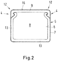
- Fig. 2
- eine Schnittdarstellung des Kabelkanals, gemäß
Fig. 1 ; - Fig. 3
- eine Teilansicht der Verschlusseinrichtung des Deckels im Schnitt.
- In
Fig. 1 ist eine Vorrichtung 1 zur Aufnahme von Leitungen, Kabeln 2 oder stromleitenden Teilen in einem länglichen, ein Kanalgehäuse 7 aufweisenden Kanal oder Kabelkanal 3 dargestellt, die mit Hilfe einer Verschlusseinrichtung 4 verschließbar ist, die mit dem Kanalgehäuse verbunden werden kann. - Das Kanalgehäuse 7 besteht aus mindestens zwei mit einander verbundenen Schichten, wobei die erste Schicht 5 die zweite Schicht 6 des Kanalgehäuses 7 zumindest an einigen Seiten oder auch ganz umgibt. Die untere Seite muss nur in bestimmten Fällen mit einer zweiten Schicht versehen sein.
- Die erste oder äußere Schicht 5 kann als Werbeträger oder Dekorschicht ausgebildet sein. Deshalb ist es vorteilhaft, dass die erste oder äußere Schicht 5 als Metallschicht oder Metallband ausgebildet ist.
- Die zweite einen Hohlraum 8 des Kanalgehäuses 7 umschließende Schicht 6 ist aus Kunststoff oder zumindest teilweise elastischem Kunststoff gebildet und dient zur Aufnahme von Kabeln oder anderen länglichen Teilen. Die innere Schicht 6 kann auch als Isolierschicht dienen.
- Ein Teil, insbesondere der obere Teil des Kanalgehäuses 7, ist als Deckel 9 ausgebildet, der auf die Öffnung des Kanalgehäuses 7 aufgesetzt werden kann und mit Hilfe einer oder zwei Verschlusseinrichtungen 4 am Kabelgehäuses 7 gesichert werden kann, wenn, wie zuvor erwähnt, die Kabel in das Kabelgehäuses verlegt worden sind.
- Die Verschlusseinrichtung 4 besteht aus einem teilweise elastisch ausgebildeten Haken 10 und einem Widerlager 11, die miteinander fest verbindbar sind. Der Haken ist gemäß
Fig. 3 an ein aufrecht stehendes Wandteil 13 geformt und nach innen bzw. in das Gehäuseinnere abgewinkelt. Der schrägverlaufende Teil des Hakens bildet eine Führungsfläche 15, gegen die sich die gegenüberliegende Seite eines Teils des Widerlagers 11 anlegen kann, wenn der Deckel 9 auf das Kabelgehäuse 7 gesetzt wird. - Der Fuß oder die Anschlussstelle des Hakens 10 ist an das Wandteil 13 des Kabelgehäuses 7 elastisch angeschlossen, oder als Gelenkstelle derart verstellbar ausgebildet, dass beim Schließen des Deckels 9 am Kabelgehäuse 7 ein Teil des Hakens 10 durch Anlage an einer geneigt verlaufenden Führungsfläche 15 etwas zurückgebogen und an dieser entlanggeführt wird, bis er hinter der Führungsfläche 15 mit Hilfe seiner Federkraft in eine Aussparung 14 eingeführt und gegen das Widerlager gepresst wird und somit den Deckel 9 am Kanalgehäuse 7 sichert.
- Beide Verschlusseinrichtungen 4 sind jeweils in einem Eckbereich 12 des Kanalgehäuses 7 vorgesehen.
- Das Kanalgehäuse 7 kann rundes, ovales viereckiges oder mehreckiges Gehäuse ausgebildet sein, dessen Wandteile 13 allseitig eine durchgehend flache glatte Oberfläche 16 bilden, wobei der Haken 10 und das Widerlager 11 so in die Teile des Kanalgehäuses 7 eingeformt sind, dass sie an der äußeren Oberfläche 16 der Wandteile 13 des Kanalgehäuses 7 nicht hervorstehen. Hierdurch ist es ohne weiteres möglich, alle äußeren Flächen als Dekorflächen einzusetzen.
- Damit ein Ende 17 der ersten Schicht oder des Metallbands 5 gegen Abheben gesichert ist, kann das untere freie Ende des Metallbands zwischen der Führungsfläche 15 des Widerlagers 11 und der gegenüberliegenden Oberfläche des Hakens 10 platziert werden.
-
- 1
- Vorrichtung
- 2
- Leitung, Kabel
- 3
- Kanal, Kabelkanal
- 4
- Verschlusseinrichtung
- 5
- erste Schicht, äußere Schicht, Metallband, Dekorschicht oder Folie
- 6
- zweite Schicht
- 7
- Kanalgehäuse
- 8
- Hohlraum
- 9
- Deckel
- 10
- Haken
- 11
- Widerlager
- 12
- Eckbereich
- 13
- Wandteil
- 14
- Aussparung
- 15
- Führungsfläche
- 16
- flache glatte Oberfläche
- 17
- Ende der ersten Schicht
Claims (10)
- Vorrichtung (1) zur Aufnahme von Leitungen, Kabeln (2) oder stromleitenden Teilen in einem länglichen, ein Kanalgehäuse (7) aufweisenden Kanal oder Kabelkanal (3), der mit Hilfe einer Verschlusseinrichtung (4) verschließbar ist, die mit dem Kanalgehäuse verbunden werden kann,
dadurch gekennzeichnet,
dass das Kanalgehäuse (7) aus mindestens zwei mit einander verbundenen Schichten besteht, wobei die erste Schicht (5) die zweite Schicht (6) des Kanalgehäuses (7) zumindest an einigen Seiten oder auch ganz umgibt. - Vorrichtung nach Anspruch 1,
dadurch gekennzeichnet,
dass die erste oder äußere Schicht (5) als Dekorschicht oder Folie ausgebildet ist. - Vorrichtung nach Anspruch 1 oder 2,
dadurch gekennzeichnet,
dass die erste oder äußere Schicht (5) als Metallschicht oder Metallband ausgebildet ist. - Vorrichtung nach einem der vorhergehenden Ansprüche,
dadurch gekennzeichnet,
dass die zweite einen Hohlraum (8) des Kanalgehäuses (7) umschließende Schicht (6) aus Kunststoff oder zumindest teilweise elastischem Kunststoff gebildet ist. - Vorrichtung nach einem der vorhergehenden Ansprüche,
dadurch gekennzeichnet,
dass ein Teil des Kanalgehäuses (7) als Deckel (9) ausgebildet ist, der auf die Öffnung des Kanalgehäuses (7) mit Hilfe der Verschlusseinrichtung (4) am Kanalgehäuse (7) gesichert werden kann. - Vorrichtung nach einem der vorhergehenden Ansprüche,
dadurch gekennzeichnet,
dass die Verschlusseinrichtung (4) aus einem teilweise elastisch ausgebildeten Haken (10) und einem Widerlager (11) besteht, die miteinander fest verbindbar sind, wobei ein Teil der Verschlusseinrichtung (4) am
Deckel (9) und der andere Teil am Kanalgehäuse (7) befestigt oder diesem angeformt ist. - Vorrichtung nach einem der vorhergehenden Ansprüche,
dadurch gekennzeichnet,
dass der Fuß oder die Anschlussstelle des Hakens (10) an einem Wandteil (13) des Kanalgehäuses (7) elastisch, als Gelenkstelle oder derart verstellbar ausgebildet ist, dass beim Schließen des Deckels (9) am Kanalgehäuse (7) ein Teil des Hakens (10) durch Anlage an einer geneigt verlaufenden Führungsfläche (15) etwas zurückgebogen und an dieser entlanggeführt wird, bis er hinter der Führungsfläche (15) mit Hilfe seiner Federkraft in eine Aussparung (14) eingeführt und gegen das Widerlager gepresst wird und somit den Deckel (9) am Kanalgehäuse (7) sichert. - Vorrichtung nach einem der vorhergehenden Ansprüche,
dadurch gekennzeichnet,
dass beide Verschlusseinrichtungen (4) jeweils in einem Eckbereich (12) des Kanalgehäuses (7) vorgesehen sind. - Vorrichtung nach einem der vorhergehenden Ansprüche,
dadurch gekennzeichnet,
dass das Kanalgehäuse (7) als viereckiges oder mehreckiges Gehäuse ausgebildet ist, dessen Wandteile (13) allseitig eine durchgehend flache glatte Oberfläche (16) bilden, wobei der Haken (10) und das Widerlager (11) so in die Teile des Kanalgehäuses (7) eingeformt sind, dass sie an der äußeren Oberfläche (16) der Wandteile (13) des Kanalgehäuses (7) nicht hervorstehen. - Vorrichtung nach einem der vorhergehenden Ansprüche,
dadurch gekennzeichnet,
dass ein Ende (17) der ersten Schicht oder des Metallbands (5) das untere freie Ende des Widerlagers (11) ummantelt und zwar zwischen der Führungsfläche (15) des Widerlagers (11) und der gegenüberliegenden Oberfläche des Hakens (10).
Priority Applications (2)
| Application Number | Priority Date | Filing Date | Title |
|---|---|---|---|
| ES18173948T ES3041965T3 (en) | 2018-05-24 | 2018-05-24 | Device for receiving circuits; cables or electrically conducting parts |
| EP18173948.3A EP3573201B1 (de) | 2018-05-24 | 2018-05-24 | Vorichtung zur aufnahme von leitungen; kabeln oder stromleitenden teilen |
Applications Claiming Priority (1)
| Application Number | Priority Date | Filing Date | Title |
|---|---|---|---|
| EP18173948.3A EP3573201B1 (de) | 2018-05-24 | 2018-05-24 | Vorichtung zur aufnahme von leitungen; kabeln oder stromleitenden teilen |
Publications (3)
| Publication Number | Publication Date |
|---|---|
| EP3573201A1 true EP3573201A1 (de) | 2019-11-27 |
| EP3573201B1 EP3573201B1 (de) | 2025-07-02 |
| EP3573201C0 EP3573201C0 (de) | 2025-07-02 |
Family
ID=62245189
Family Applications (1)
| Application Number | Title | Priority Date | Filing Date |
|---|---|---|---|
| EP18173948.3A Active EP3573201B1 (de) | 2018-05-24 | 2018-05-24 | Vorichtung zur aufnahme von leitungen; kabeln oder stromleitenden teilen |
Country Status (2)
| Country | Link |
|---|---|
| EP (1) | EP3573201B1 (de) |
| ES (1) | ES3041965T3 (de) |
Citations (6)
| Publication number | Priority date | Publication date | Assignee | Title |
|---|---|---|---|---|
| US4258515A (en) * | 1977-09-13 | 1981-03-31 | Owen William J | Conduit trunking |
| GB2307111A (en) * | 1995-11-11 | 1997-05-14 | Caradon Mk Electric Ltd | Electrical Trunking |
| DE20021565U1 (de) * | 2000-12-21 | 2001-06-13 | Extruplast GmbH, 77746 Schutterwald | Kabelkanal |
| GB2362270A (en) * | 2000-05-10 | 2001-11-14 | Caradon Mk Electric Ltd | Improvements in and relating to electrical trunking |
| DE10056441A1 (de) * | 2000-11-14 | 2002-05-29 | Rehau Ag & Co | Kabelkanal und Verfahren zu seiner Herstellung |
| EP3264546A1 (de) | 2016-06-30 | 2018-01-03 | Hellermanntyton Corporation | Kabelrinne |
-
2018
- 2018-05-24 ES ES18173948T patent/ES3041965T3/es active Active
- 2018-05-24 EP EP18173948.3A patent/EP3573201B1/de active Active
Patent Citations (6)
| Publication number | Priority date | Publication date | Assignee | Title |
|---|---|---|---|---|
| US4258515A (en) * | 1977-09-13 | 1981-03-31 | Owen William J | Conduit trunking |
| GB2307111A (en) * | 1995-11-11 | 1997-05-14 | Caradon Mk Electric Ltd | Electrical Trunking |
| GB2362270A (en) * | 2000-05-10 | 2001-11-14 | Caradon Mk Electric Ltd | Improvements in and relating to electrical trunking |
| DE10056441A1 (de) * | 2000-11-14 | 2002-05-29 | Rehau Ag & Co | Kabelkanal und Verfahren zu seiner Herstellung |
| DE20021565U1 (de) * | 2000-12-21 | 2001-06-13 | Extruplast GmbH, 77746 Schutterwald | Kabelkanal |
| EP3264546A1 (de) | 2016-06-30 | 2018-01-03 | Hellermanntyton Corporation | Kabelrinne |
Non-Patent Citations (1)
| Title |
|---|
| MK ELECTRIC: "MK Product Catalogue cable management", 1 March 2009 (2009-03-01), pages 114 - 187, XP055524303, Retrieved from the Internet <URL:https://www.mkelectric.com/Documents/Middle%20East/MK%20Electric%20Cable%20Management%20Technical%20Brochure%20(Middle%20East).pdf> [retrieved on 20181115] * |
Also Published As
| Publication number | Publication date |
|---|---|
| ES3041965T3 (en) | 2025-11-17 |
| EP3573201B1 (de) | 2025-07-02 |
| EP3573201C0 (de) | 2025-07-02 |
Similar Documents
| Publication | Publication Date | Title |
|---|---|---|
| EP1606867B1 (de) | Kabeldurchführungsvorrichtung | |
| DE102010005841B4 (de) | Kabelschuh mit schalenförmiger Ausformung und Befestigungseinrichtung | |
| DE102009004513A1 (de) | Klemmfeder für eine Federkraftklemme | |
| DE102019101402A1 (de) | Batteriegehäuse für ein elektromotorisch betriebenes Fahrzeug | |
| EP3350883A1 (de) | Leiteranschlusskontaktelement | |
| DE102009021033A1 (de) | Bedieneinrichtung und Verfahren zur Herstellung einer Bedieneinrichtung | |
| EP1659411A1 (de) | Elektronischer Elektrizitätszähler | |
| EP1595318A1 (de) | Kabeldurchführung | |
| EP0175236B1 (de) | Vorrichtung zur Einführung eines Flachkabels | |
| DE2748872C2 (de) | Gehäuse mit Schaltungsplatine für Koaxialkabel | |
| EP3573201B1 (de) | Vorichtung zur aufnahme von leitungen; kabeln oder stromleitenden teilen | |
| EP3172834A1 (de) | Anschlussdose für ein photovoltaikmodul | |
| DE2838433C2 (de) | Befestigungsvorrichtung für das Ende eines Elektrokabels o.dgl. | |
| DE29817464U1 (de) | Anschlußset für ein elektrisches Gerät | |
| DE4421588A1 (de) | Anordnung für elektromagnetisch abschirmende Durchführungen für elektrische Kabel durch eine elektromagnetisch abschirmende Wand | |
| DE202018002133U1 (de) | Sicherheitskontaktleiste | |
| DE102016120021A1 (de) | Kabeldurchführung für Tischplatten | |
| AT405999B (de) | Gehäuse | |
| DE102012016597B3 (de) | Vorrichtung zur Befestigung mindestens einer elektrischen Leitung in einer Wandöffnung | |
| EP1061611A2 (de) | Einrichtung zur Zugentlastung für Kabel | |
| DE19732317B4 (de) | Elektromagnetischer Rauschabsorber | |
| DE19615143C2 (de) | Kabelverteilerschrank | |
| DE19742809C1 (de) | Kabelklemme mit Schutzklappe | |
| DE9004652U1 (de) | Vorrichtung zur Abschirmung der Gehäusetüren von Computergehäusen od.dgl. gegen elektrische Strahlung | |
| AT404530B (de) | Gehäuse |
Legal Events
| Date | Code | Title | Description |
|---|---|---|---|
| PUAI | Public reference made under article 153(3) epc to a published international application that has entered the european phase |
Free format text: ORIGINAL CODE: 0009012 |
|
| STAA | Information on the status of an ep patent application or granted ep patent |
Free format text: STATUS: THE APPLICATION HAS BEEN PUBLISHED |
|
| AK | Designated contracting states |
Kind code of ref document: A1 Designated state(s): AL AT BE BG CH CY CZ DE DK EE ES FI FR GB GR HR HU IE IS IT LI LT LU LV MC MK MT NL NO PL PT RO RS SE SI SK SM TR |
|
| AX | Request for extension of the european patent |
Extension state: BA ME |
|
| STAA | Information on the status of an ep patent application or granted ep patent |
Free format text: STATUS: REQUEST FOR EXAMINATION WAS MADE |
|
| 17P | Request for examination filed |
Effective date: 20191209 |
|
| STAA | Information on the status of an ep patent application or granted ep patent |
Free format text: STATUS: EXAMINATION IS IN PROGRESS |
|
| 17Q | First examination report despatched |
Effective date: 20200204 |
|
| RBV | Designated contracting states (corrected) |
Designated state(s): AL AT BE BG CH CY CZ DE DK EE ES FI FR GB GR HR HU IE IS IT LI LT LU LV MC MK MT NL NO PL PT RO RS SE SI SK SM TR |
|
| GRAP | Despatch of communication of intention to grant a patent |
Free format text: ORIGINAL CODE: EPIDOSNIGR1 |
|
| STAA | Information on the status of an ep patent application or granted ep patent |
Free format text: STATUS: GRANT OF PATENT IS INTENDED |
|
| INTG | Intention to grant announced |
Effective date: 20250131 |
|
| GRAS | Grant fee paid |
Free format text: ORIGINAL CODE: EPIDOSNIGR3 |
|
| GRAA | (expected) grant |
Free format text: ORIGINAL CODE: 0009210 |
|
| STAA | Information on the status of an ep patent application or granted ep patent |
Free format text: STATUS: THE PATENT HAS BEEN GRANTED |
|
| AK | Designated contracting states |
Kind code of ref document: B1 Designated state(s): AL AT BE BG CH CY CZ DE DK EE ES FI FR GB GR HR HU IE IS IT LI LT LU LV MC MK MT NL NO PL PT RO RS SE SI SK SM TR |
|
| REG | Reference to a national code |
Ref country code: GB Ref legal event code: FG4D Free format text: NOT ENGLISH |
|
| REG | Reference to a national code |
Ref country code: CH Ref legal event code: EP |
|
| REG | Reference to a national code |
Ref country code: DE Ref legal event code: R096 Ref document number: 502018015918 Country of ref document: DE |
|
| REG | Reference to a national code |
Ref country code: IE Ref legal event code: FG4D Free format text: LANGUAGE OF EP DOCUMENT: GERMAN |
|
| U01 | Request for unitary effect filed |
Effective date: 20250731 |
|
| U07 | Unitary effect registered |
Designated state(s): AT BE BG DE DK EE FI FR IT LT LU LV MT NL PT RO SE SI Effective date: 20250808 |
|
| REG | Reference to a national code |
Ref country code: ES Ref legal event code: FG2A Ref document number: 3041965 Country of ref document: ES Kind code of ref document: T3 Effective date: 20251117 |
|
| PG25 | Lapsed in a contracting state [announced via postgrant information from national office to epo] |
Ref country code: IS Free format text: LAPSE BECAUSE OF FAILURE TO SUBMIT A TRANSLATION OF THE DESCRIPTION OR TO PAY THE FEE WITHIN THE PRESCRIBED TIME-LIMIT Effective date: 20251102 |
|
| PG25 | Lapsed in a contracting state [announced via postgrant information from national office to epo] |
Ref country code: NO Free format text: LAPSE BECAUSE OF FAILURE TO SUBMIT A TRANSLATION OF THE DESCRIPTION OR TO PAY THE FEE WITHIN THE PRESCRIBED TIME-LIMIT Effective date: 20251002 |
|
| PG25 | Lapsed in a contracting state [announced via postgrant information from national office to epo] |
Ref country code: HR Free format text: LAPSE BECAUSE OF FAILURE TO SUBMIT A TRANSLATION OF THE DESCRIPTION OR TO PAY THE FEE WITHIN THE PRESCRIBED TIME-LIMIT Effective date: 20250702 |
|
| PG25 | Lapsed in a contracting state [announced via postgrant information from national office to epo] |
Ref country code: GR Free format text: LAPSE BECAUSE OF FAILURE TO SUBMIT A TRANSLATION OF THE DESCRIPTION OR TO PAY THE FEE WITHIN THE PRESCRIBED TIME-LIMIT Effective date: 20251003 |
|
| PG25 | Lapsed in a contracting state [announced via postgrant information from national office to epo] |
Ref country code: CZ Free format text: LAPSE BECAUSE OF FAILURE TO SUBMIT A TRANSLATION OF THE DESCRIPTION OR TO PAY THE FEE WITHIN THE PRESCRIBED TIME-LIMIT Effective date: 20250702 |
|
| PG25 | Lapsed in a contracting state [announced via postgrant information from national office to epo] |
Ref country code: RS Free format text: LAPSE BECAUSE OF FAILURE TO SUBMIT A TRANSLATION OF THE DESCRIPTION OR TO PAY THE FEE WITHIN THE PRESCRIBED TIME-LIMIT Effective date: 20251002 |
|
| REG | Reference to a national code |
Ref country code: HU Ref legal event code: AG4A Ref document number: E073579 Country of ref document: HU |
|
| PG25 | Lapsed in a contracting state [announced via postgrant information from national office to epo] |
Ref country code: SM Free format text: LAPSE BECAUSE OF FAILURE TO SUBMIT A TRANSLATION OF THE DESCRIPTION OR TO PAY THE FEE WITHIN THE PRESCRIBED TIME-LIMIT Effective date: 20250702 |
|
| PG25 | Lapsed in a contracting state [announced via postgrant information from national office to epo] |
Ref country code: SK Free format text: LAPSE BECAUSE OF FAILURE TO SUBMIT A TRANSLATION OF THE DESCRIPTION OR TO PAY THE FEE WITHIN THE PRESCRIBED TIME-LIMIT Effective date: 20250702 |
|
| PLBE | No opposition filed within time limit |
Free format text: ORIGINAL CODE: 0009261 |
|
| STAA | Information on the status of an ep patent application or granted ep patent |
Free format text: STATUS: NO OPPOSITION FILED WITHIN TIME LIMIT |
|
| REG | Reference to a national code |
Ref country code: CH Ref legal event code: L10 Free format text: ST27 STATUS EVENT CODE: U-0-0-L10-L00 (AS PROVIDED BY THE NATIONAL OFFICE) Effective date: 20260518 |
|
| 26N | No opposition filed |
Effective date: 20260407 |