EP3573141A1 - Anode au lithium et son procédé de fabrication - Google Patents
Anode au lithium et son procédé de fabrication Download PDFInfo
- Publication number
- EP3573141A1 EP3573141A1 EP19176015.6A EP19176015A EP3573141A1 EP 3573141 A1 EP3573141 A1 EP 3573141A1 EP 19176015 A EP19176015 A EP 19176015A EP 3573141 A1 EP3573141 A1 EP 3573141A1
- Authority
- EP
- European Patent Office
- Prior art keywords
- lithium
- anode
- active material
- anode active
- cavities
- Prior art date
- Legal status (The legal status is an assumption and is not a legal conclusion. Google has not performed a legal analysis and makes no representation as to the accuracy of the status listed.)
- Granted
Links
- 229910052744 lithium Inorganic materials 0.000 title claims abstract description 149
- WHXSMMKQMYFTQS-UHFFFAOYSA-N Lithium Chemical compound [Li] WHXSMMKQMYFTQS-UHFFFAOYSA-N 0.000 title claims abstract description 146
- 238000004519 manufacturing process Methods 0.000 title claims abstract description 16
- 238000000034 method Methods 0.000 title claims description 52
- 239000004020 conductor Substances 0.000 claims abstract description 155
- 239000006183 anode active material Substances 0.000 claims abstract description 105
- 238000000576 coating method Methods 0.000 claims abstract description 76
- 239000011248 coating agent Substances 0.000 claims abstract description 71
- 229910001416 lithium ion Inorganic materials 0.000 claims description 46
- 239000000463 material Substances 0.000 claims description 36
- HBBGRARXTFLTSG-UHFFFAOYSA-N Lithium ion Chemical compound [Li+] HBBGRARXTFLTSG-UHFFFAOYSA-N 0.000 claims description 32
- 230000008569 process Effects 0.000 claims description 20
- OKTJSMMVPCPJKN-UHFFFAOYSA-N Carbon Chemical compound [C] OKTJSMMVPCPJKN-UHFFFAOYSA-N 0.000 claims description 18
- 229910052751 metal Inorganic materials 0.000 claims description 13
- 239000002184 metal Substances 0.000 claims description 13
- 239000003575 carbonaceous material Substances 0.000 claims description 11
- 229910002804 graphite Inorganic materials 0.000 claims description 10
- 239000010439 graphite Substances 0.000 claims description 10
- 238000007598 dipping method Methods 0.000 claims description 8
- 229910052799 carbon Inorganic materials 0.000 claims description 7
- RYGMFSIKBFXOCR-UHFFFAOYSA-N Copper Chemical compound [Cu] RYGMFSIKBFXOCR-UHFFFAOYSA-N 0.000 claims description 6
- 239000011888 foil Substances 0.000 claims description 6
- 238000005304 joining Methods 0.000 claims description 6
- 238000005096 rolling process Methods 0.000 claims description 6
- 229910002986 Li4Ti5O12 Inorganic materials 0.000 claims description 5
- 229910052802 copper Inorganic materials 0.000 claims description 5
- 239000010949 copper Substances 0.000 claims description 5
- 239000007769 metal material Substances 0.000 claims description 4
- RTAQQCXQSZGOHL-UHFFFAOYSA-N Titanium Chemical compound [Ti] RTAQQCXQSZGOHL-UHFFFAOYSA-N 0.000 claims description 3
- 239000002001 electrolyte material Substances 0.000 claims description 3
- 229910021385 hard carbon Inorganic materials 0.000 claims description 3
- 238000003754 machining Methods 0.000 claims description 3
- 229910021384 soft carbon Inorganic materials 0.000 claims description 3
- 239000010410 layer Substances 0.000 description 66
- 238000009830 intercalation Methods 0.000 description 19
- 238000011049 filling Methods 0.000 description 18
- 230000002687 intercalation Effects 0.000 description 16
- 239000011855 lithium-based material Substances 0.000 description 16
- XUIMIQQOPSSXEZ-UHFFFAOYSA-N Silicon Chemical compound [Si] XUIMIQQOPSSXEZ-UHFFFAOYSA-N 0.000 description 15
- 230000008859 change Effects 0.000 description 15
- 229910052710 silicon Inorganic materials 0.000 description 15
- 239000010703 silicon Substances 0.000 description 15
- 238000011161 development Methods 0.000 description 12
- 239000002210 silicon-based material Substances 0.000 description 12
- 238000002360 preparation method Methods 0.000 description 8
- 238000013461 design Methods 0.000 description 7
- 230000000694 effects Effects 0.000 description 7
- 238000013459 approach Methods 0.000 description 6
- IIPYXGDZVMZOAP-UHFFFAOYSA-N lithium nitrate Chemical compound [Li+].[O-][N+]([O-])=O IIPYXGDZVMZOAP-UHFFFAOYSA-N 0.000 description 6
- 238000004544 sputter deposition Methods 0.000 description 6
- 230000015572 biosynthetic process Effects 0.000 description 5
- 239000006182 cathode active material Substances 0.000 description 5
- 239000010406 cathode material Substances 0.000 description 5
- 229910000625 lithium cobalt oxide Inorganic materials 0.000 description 5
- 238000007740 vapor deposition Methods 0.000 description 5
- 239000010405 anode material Substances 0.000 description 4
- 239000011230 binding agent Substances 0.000 description 4
- 238000009831 deintercalation Methods 0.000 description 4
- 238000000151 deposition Methods 0.000 description 4
- 238000007735 ion beam assisted deposition Methods 0.000 description 4
- 239000007788 liquid Substances 0.000 description 4
- 239000000203 mixture Substances 0.000 description 4
- 239000002245 particle Substances 0.000 description 4
- 239000011241 protective layer Substances 0.000 description 4
- XEEYBQQBJWHFJM-UHFFFAOYSA-N Iron Chemical compound [Fe] XEEYBQQBJWHFJM-UHFFFAOYSA-N 0.000 description 3
- 229910052493 LiFePO4 Inorganic materials 0.000 description 3
- 229910000572 Lithium Nickel Cobalt Manganese Oxide (NCM) Inorganic materials 0.000 description 3
- 239000011149 active material Substances 0.000 description 3
- 229910052782 aluminium Inorganic materials 0.000 description 3
- XAGFODPZIPBFFR-UHFFFAOYSA-N aluminium Chemical compound [Al] XAGFODPZIPBFFR-UHFFFAOYSA-N 0.000 description 3
- 238000001311 chemical methods and process Methods 0.000 description 3
- 230000008021 deposition Effects 0.000 description 3
- 239000003792 electrolyte Substances 0.000 description 3
- 238000005566 electron beam evaporation Methods 0.000 description 3
- 230000008020 evaporation Effects 0.000 description 3
- 238000001704 evaporation Methods 0.000 description 3
- 230000037427 ion transport Effects 0.000 description 3
- 150000002500 ions Chemical class 0.000 description 3
- 238000009940 knitting Methods 0.000 description 3
- 239000000843 powder Substances 0.000 description 3
- 238000003672 processing method Methods 0.000 description 3
- 229910012851 LiCoO 2 Inorganic materials 0.000 description 2
- PXHVJJICTQNCMI-UHFFFAOYSA-N Nickel Chemical compound [Ni] PXHVJJICTQNCMI-UHFFFAOYSA-N 0.000 description 2
- 229910045601 alloy Inorganic materials 0.000 description 2
- 239000000956 alloy Substances 0.000 description 2
- 238000000231 atomic layer deposition Methods 0.000 description 2
- 230000008901 benefit Effects 0.000 description 2
- 230000001680 brushing effect Effects 0.000 description 2
- 238000000541 cathodic arc deposition Methods 0.000 description 2
- 238000005229 chemical vapour deposition Methods 0.000 description 2
- 239000002131 composite material Substances 0.000 description 2
- 238000009826 distribution Methods 0.000 description 2
- 239000007772 electrode material Substances 0.000 description 2
- 238000005516 engineering process Methods 0.000 description 2
- 238000010348 incorporation Methods 0.000 description 2
- 238000000608 laser ablation Methods 0.000 description 2
- PQXKHYXIUOZZFA-UHFFFAOYSA-M lithium fluoride Chemical compound [Li+].[F-] PQXKHYXIUOZZFA-UHFFFAOYSA-M 0.000 description 2
- FUJCRWPEOMXPAD-UHFFFAOYSA-N lithium oxide Chemical compound [Li+].[Li+].[O-2] FUJCRWPEOMXPAD-UHFFFAOYSA-N 0.000 description 2
- 229910001947 lithium oxide Inorganic materials 0.000 description 2
- BFZPBUKRYWOWDV-UHFFFAOYSA-N lithium;oxido(oxo)cobalt Chemical compound [Li+].[O-][Co]=O BFZPBUKRYWOWDV-UHFFFAOYSA-N 0.000 description 2
- 238000011068 loading method Methods 0.000 description 2
- 239000011159 matrix material Substances 0.000 description 2
- 229910044991 metal oxide Inorganic materials 0.000 description 2
- 150000004706 metal oxides Chemical class 0.000 description 2
- 238000001451 molecular beam epitaxy Methods 0.000 description 2
- 239000002071 nanotube Substances 0.000 description 2
- 238000007747 plating Methods 0.000 description 2
- BASFCYQUMIYNBI-UHFFFAOYSA-N platinum Chemical compound [Pt] BASFCYQUMIYNBI-UHFFFAOYSA-N 0.000 description 2
- 238000004549 pulsed laser deposition Methods 0.000 description 2
- 239000002994 raw material Substances 0.000 description 2
- 239000007787 solid Substances 0.000 description 2
- 239000007784 solid electrolyte Substances 0.000 description 2
- 239000007858 starting material Substances 0.000 description 2
- 238000003860 storage Methods 0.000 description 2
- BHZCMUVGYXEBMY-UHFFFAOYSA-N trilithium;azanide Chemical compound [Li+].[Li+].[Li+].[NH2-] BHZCMUVGYXEBMY-UHFFFAOYSA-N 0.000 description 2
- PNEYBMLMFCGWSK-UHFFFAOYSA-N Alumina Chemical compound [O-2].[O-2].[O-2].[Al+3].[Al+3] PNEYBMLMFCGWSK-UHFFFAOYSA-N 0.000 description 1
- 229910003528 Li(Ni,Co,Al)O2 Inorganic materials 0.000 description 1
- 229910003548 Li(Ni,Co,Mn)O2 Inorganic materials 0.000 description 1
- 229910004183 Li(NiCoAl)O2 Inorganic materials 0.000 description 1
- 229910004235 Li(NiCoMn)O2 Inorganic materials 0.000 description 1
- 229910010707 LiFePO 4 Inorganic materials 0.000 description 1
- FYYHWMGAXLPEAU-UHFFFAOYSA-N Magnesium Chemical compound [Mg] FYYHWMGAXLPEAU-UHFFFAOYSA-N 0.000 description 1
- 229910000792 Monel Inorganic materials 0.000 description 1
- 229910019142 PO4 Inorganic materials 0.000 description 1
- 229910000676 Si alloy Inorganic materials 0.000 description 1
- VYPSYNLAJGMNEJ-UHFFFAOYSA-N Silicium dioxide Chemical compound O=[Si]=O VYPSYNLAJGMNEJ-UHFFFAOYSA-N 0.000 description 1
- 229910000831 Steel Inorganic materials 0.000 description 1
- ATJFFYVFTNAWJD-UHFFFAOYSA-N Tin Chemical compound [Sn] ATJFFYVFTNAWJD-UHFFFAOYSA-N 0.000 description 1
- QCWXUUIWCKQGHC-UHFFFAOYSA-N Zirconium Chemical compound [Zr] QCWXUUIWCKQGHC-UHFFFAOYSA-N 0.000 description 1
- 238000004026 adhesive bonding Methods 0.000 description 1
- 238000003491 array Methods 0.000 description 1
- 230000009172 bursting Effects 0.000 description 1
- 239000002134 carbon nanofiber Substances 0.000 description 1
- 239000002041 carbon nanotube Substances 0.000 description 1
- 229910021393 carbon nanotube Inorganic materials 0.000 description 1
- 230000015556 catabolic process Effects 0.000 description 1
- 239000003795 chemical substances by application Substances 0.000 description 1
- 238000005253 cladding Methods 0.000 description 1
- 238000004891 communication Methods 0.000 description 1
- 150000001875 compounds Chemical class 0.000 description 1
- 238000010276 construction Methods 0.000 description 1
- 230000007797 corrosion Effects 0.000 description 1
- 238000005260 corrosion Methods 0.000 description 1
- 230000008878 coupling Effects 0.000 description 1
- 238000010168 coupling process Methods 0.000 description 1
- 238000005859 coupling reaction Methods 0.000 description 1
- 238000005520 cutting process Methods 0.000 description 1
- 125000004122 cyclic group Chemical group 0.000 description 1
- 230000001351 cycling effect Effects 0.000 description 1
- 238000006731 degradation reaction Methods 0.000 description 1
- 238000005137 deposition process Methods 0.000 description 1
- 238000004070 electrodeposition Methods 0.000 description 1
- 238000005868 electrolysis reaction Methods 0.000 description 1
- 239000004744 fabric Substances 0.000 description 1
- 239000000835 fiber Substances 0.000 description 1
- 229910052732 germanium Inorganic materials 0.000 description 1
- GNPVGFCGXDBREM-UHFFFAOYSA-N germanium atom Chemical compound [Ge] GNPVGFCGXDBREM-UHFFFAOYSA-N 0.000 description 1
- PCHJSUWPFVWCPO-UHFFFAOYSA-N gold Chemical compound [Au] PCHJSUWPFVWCPO-UHFFFAOYSA-N 0.000 description 1
- 229910052737 gold Inorganic materials 0.000 description 1
- 239000010931 gold Substances 0.000 description 1
- 229910003474 graphite-silicon composite material Inorganic materials 0.000 description 1
- 230000006872 improvement Effects 0.000 description 1
- 238000010849 ion bombardment Methods 0.000 description 1
- 238000007733 ion plating Methods 0.000 description 1
- 229910052742 iron Inorganic materials 0.000 description 1
- 230000002427 irreversible effect Effects 0.000 description 1
- 150000002641 lithium Chemical class 0.000 description 1
- 229910003002 lithium salt Inorganic materials 0.000 description 1
- 159000000002 lithium salts Chemical class 0.000 description 1
- 229910052749 magnesium Inorganic materials 0.000 description 1
- 239000011777 magnesium Substances 0.000 description 1
- 239000012528 membrane Substances 0.000 description 1
- 229910052752 metalloid Inorganic materials 0.000 description 1
- 150000002738 metalloids Chemical class 0.000 description 1
- JHJNPOSPVGRIAN-SFHVURJKSA-N n-[3-[(1s)-1-[[6-(3,4-dimethoxyphenyl)pyrazin-2-yl]amino]ethyl]phenyl]-5-methylpyridine-3-carboxamide Chemical compound C1=C(OC)C(OC)=CC=C1C1=CN=CC(N[C@@H](C)C=2C=C(NC(=O)C=3C=C(C)C=NC=3)C=CC=2)=N1 JHJNPOSPVGRIAN-SFHVURJKSA-N 0.000 description 1
- 239000002159 nanocrystal Substances 0.000 description 1
- 239000002120 nanofilm Substances 0.000 description 1
- 239000002105 nanoparticle Substances 0.000 description 1
- 239000002070 nanowire Substances 0.000 description 1
- 229910021382 natural graphite Inorganic materials 0.000 description 1
- 239000007773 negative electrode material Substances 0.000 description 1
- 230000007935 neutral effect Effects 0.000 description 1
- 229910052759 nickel Inorganic materials 0.000 description 1
- NBIIXXVUZAFLBC-UHFFFAOYSA-K phosphate Chemical compound [O-]P([O-])([O-])=O NBIIXXVUZAFLBC-UHFFFAOYSA-K 0.000 description 1
- 239000010452 phosphate Substances 0.000 description 1
- 238000005240 physical vapour deposition Methods 0.000 description 1
- 229910052697 platinum Inorganic materials 0.000 description 1
- 239000002952 polymeric resin Substances 0.000 description 1
- 239000011148 porous material Substances 0.000 description 1
- 230000008092 positive effect Effects 0.000 description 1
- 239000002243 precursor Substances 0.000 description 1
- 238000003825 pressing Methods 0.000 description 1
- 238000007363 ring formation reaction Methods 0.000 description 1
- 229910052814 silicon oxide Inorganic materials 0.000 description 1
- 239000011856 silicon-based particle Substances 0.000 description 1
- 239000002689 soil Substances 0.000 description 1
- 238000005476 soldering Methods 0.000 description 1
- 238000010025 steaming Methods 0.000 description 1
- 239000010959 steel Substances 0.000 description 1
- 239000000126 substance Substances 0.000 description 1
- 229920003002 synthetic resin Polymers 0.000 description 1
- 229910052715 tantalum Inorganic materials 0.000 description 1
- GUVRBAGPIYLISA-UHFFFAOYSA-N tantalum atom Chemical compound [Ta] GUVRBAGPIYLISA-UHFFFAOYSA-N 0.000 description 1
- 239000004753 textile Substances 0.000 description 1
- 238000002207 thermal evaporation Methods 0.000 description 1
- 229910052719 titanium Inorganic materials 0.000 description 1
- 239000010936 titanium Substances 0.000 description 1
- 238000012546 transfer Methods 0.000 description 1
- 230000007704 transition Effects 0.000 description 1
- 230000032258 transport Effects 0.000 description 1
- 238000005019 vapor deposition process Methods 0.000 description 1
- 238000009941 weaving Methods 0.000 description 1
- 238000003466 welding Methods 0.000 description 1
- 229910052726 zirconium Inorganic materials 0.000 description 1
Images


Classifications
-
- H—ELECTRICITY
- H01—ELECTRIC ELEMENTS
- H01M—PROCESSES OR MEANS, e.g. BATTERIES, FOR THE DIRECT CONVERSION OF CHEMICAL ENERGY INTO ELECTRICAL ENERGY
- H01M4/00—Electrodes
- H01M4/02—Electrodes composed of, or comprising, active material
- H01M4/36—Selection of substances as active materials, active masses, active liquids
- H01M4/362—Composites
- H01M4/366—Composites as layered products
-
- H—ELECTRICITY
- H01—ELECTRIC ELEMENTS
- H01M—PROCESSES OR MEANS, e.g. BATTERIES, FOR THE DIRECT CONVERSION OF CHEMICAL ENERGY INTO ELECTRICAL ENERGY
- H01M4/00—Electrodes
- H01M4/02—Electrodes composed of, or comprising, active material
- H01M4/64—Carriers or collectors
- H01M4/70—Carriers or collectors characterised by shape or form
- H01M4/72—Grids
- H01M4/74—Meshes or woven material; Expanded metal
-
- H—ELECTRICITY
- H01—ELECTRIC ELEMENTS
- H01M—PROCESSES OR MEANS, e.g. BATTERIES, FOR THE DIRECT CONVERSION OF CHEMICAL ENERGY INTO ELECTRICAL ENERGY
- H01M10/00—Secondary cells; Manufacture thereof
- H01M10/05—Accumulators with non-aqueous electrolyte
- H01M10/052—Li-accumulators
- H01M10/0525—Rocking-chair batteries, i.e. batteries with lithium insertion or intercalation in both electrodes; Lithium-ion batteries
-
- H—ELECTRICITY
- H01—ELECTRIC ELEMENTS
- H01M—PROCESSES OR MEANS, e.g. BATTERIES, FOR THE DIRECT CONVERSION OF CHEMICAL ENERGY INTO ELECTRICAL ENERGY
- H01M4/00—Electrodes
- H01M4/02—Electrodes composed of, or comprising, active material
- H01M4/04—Processes of manufacture in general
- H01M4/0402—Methods of deposition of the material
- H01M4/0404—Methods of deposition of the material by coating on electrode collectors
-
- H—ELECTRICITY
- H01—ELECTRIC ELEMENTS
- H01M—PROCESSES OR MEANS, e.g. BATTERIES, FOR THE DIRECT CONVERSION OF CHEMICAL ENERGY INTO ELECTRICAL ENERGY
- H01M4/00—Electrodes
- H01M4/02—Electrodes composed of, or comprising, active material
- H01M4/04—Processes of manufacture in general
- H01M4/0402—Methods of deposition of the material
- H01M4/0416—Methods of deposition of the material involving impregnation with a solution, dispersion, paste or dry powder
-
- H—ELECTRICITY
- H01—ELECTRIC ELEMENTS
- H01M—PROCESSES OR MEANS, e.g. BATTERIES, FOR THE DIRECT CONVERSION OF CHEMICAL ENERGY INTO ELECTRICAL ENERGY
- H01M4/00—Electrodes
- H01M4/02—Electrodes composed of, or comprising, active material
- H01M4/13—Electrodes for accumulators with non-aqueous electrolyte, e.g. for lithium-accumulators; Processes of manufacture thereof
- H01M4/139—Processes of manufacture
-
- H—ELECTRICITY
- H01—ELECTRIC ELEMENTS
- H01M—PROCESSES OR MEANS, e.g. BATTERIES, FOR THE DIRECT CONVERSION OF CHEMICAL ENERGY INTO ELECTRICAL ENERGY
- H01M4/00—Electrodes
- H01M4/02—Electrodes composed of, or comprising, active material
- H01M4/36—Selection of substances as active materials, active masses, active liquids
- H01M4/38—Selection of substances as active materials, active masses, active liquids of elements or alloys
- H01M4/386—Silicon or alloys based on silicon
-
- H—ELECTRICITY
- H01—ELECTRIC ELEMENTS
- H01M—PROCESSES OR MEANS, e.g. BATTERIES, FOR THE DIRECT CONVERSION OF CHEMICAL ENERGY INTO ELECTRICAL ENERGY
- H01M4/00—Electrodes
- H01M4/02—Electrodes composed of, or comprising, active material
- H01M4/36—Selection of substances as active materials, active masses, active liquids
- H01M4/48—Selection of substances as active materials, active masses, active liquids of inorganic oxides or hydroxides
- H01M4/485—Selection of substances as active materials, active masses, active liquids of inorganic oxides or hydroxides of mixed oxides or hydroxides for inserting or intercalating light metals, e.g. LiTi2O4 or LiTi2OxFy
-
- H—ELECTRICITY
- H01—ELECTRIC ELEMENTS
- H01M—PROCESSES OR MEANS, e.g. BATTERIES, FOR THE DIRECT CONVERSION OF CHEMICAL ENERGY INTO ELECTRICAL ENERGY
- H01M4/00—Electrodes
- H01M4/02—Electrodes composed of, or comprising, active material
- H01M4/64—Carriers or collectors
- H01M4/66—Selection of materials
- H01M4/661—Metal or alloys, e.g. alloy coatings
-
- H—ELECTRICITY
- H01—ELECTRIC ELEMENTS
- H01M—PROCESSES OR MEANS, e.g. BATTERIES, FOR THE DIRECT CONVERSION OF CHEMICAL ENERGY INTO ELECTRICAL ENERGY
- H01M4/00—Electrodes
- H01M4/02—Electrodes composed of, or comprising, active material
- H01M2004/021—Physical characteristics, e.g. porosity, surface area
-
- H—ELECTRICITY
- H01—ELECTRIC ELEMENTS
- H01M—PROCESSES OR MEANS, e.g. BATTERIES, FOR THE DIRECT CONVERSION OF CHEMICAL ENERGY INTO ELECTRICAL ENERGY
- H01M4/00—Electrodes
- H01M4/02—Electrodes composed of, or comprising, active material
- H01M2004/026—Electrodes composed of, or comprising, active material characterised by the polarity
- H01M2004/027—Negative electrodes
-
- Y—GENERAL TAGGING OF NEW TECHNOLOGICAL DEVELOPMENTS; GENERAL TAGGING OF CROSS-SECTIONAL TECHNOLOGIES SPANNING OVER SEVERAL SECTIONS OF THE IPC; TECHNICAL SUBJECTS COVERED BY FORMER USPC CROSS-REFERENCE ART COLLECTIONS [XRACs] AND DIGESTS
- Y02—TECHNOLOGIES OR APPLICATIONS FOR MITIGATION OR ADAPTATION AGAINST CLIMATE CHANGE
- Y02E—REDUCTION OF GREENHOUSE GAS [GHG] EMISSIONS, RELATED TO ENERGY GENERATION, TRANSMISSION OR DISTRIBUTION
- Y02E60/00—Enabling technologies; Technologies with a potential or indirect contribution to GHG emissions mitigation
- Y02E60/10—Energy storage using batteries
Definitions
- the invention relates to a lithium anode for a lithium cell and / or a lithium battery having a current collector layer, an anode active material and a coating.
- the invention further relates to a process for their preparation. Furthermore, the invention relates to a lithium battery with such a lithium anode.
- lithium batteries or even lithium-ion batteries are widely used for portable applications and for electric drives in motor vehicles.
- the term lithium battery in this context includes both batteries with lithium metal anodes and those with lithiated graphite anodes.
- lithium battery In the context of the present application, it is the technology of rechargeable lithium-ion secondary batteries, in contrast to the non-reusable primary batteries.
- the term lithium battery should also refer to such accumulators here.
- Lithium-ion batteries use carbon as a negative electrode material (when discharged: lithium anode) and metal-containing materials - usually metal oxides as a positive electrode (at discharge: cathode arrangement).
- Lithium batteries are formed from a plurality of lithium cells, which are constructed as follows: The lithium anode (first electrode) and the cathode assembly (second electrode) are separated by a separator membrane, but connected lithium ion conducting by an electrolyte passing through the electrodes. Anode and cathode are each connected to a current collector, which forms a Stromableiter Mrs. Usual cells are multi-layered. In this case, a carbon material is applied on the anode side to a current conductor layer as the anode active material and, on the cathode side, onto a current conductor layer, a cathode active material, which is generally formed by a metal oxide. Between them, a separator is arranged which separates the anode active material layer and the cathode active material layer from each other. A liquid or else solid electrolyte permeating the electrode active material allows the transport of lithium ions Li + between the electrodes.
- lithium plating which involves depositing metallic lithium at high levels Charging is avoided, as well as to achieve a longer cycle and time life.
- Such composite electrodes are for example from DE 10 2012 212 788 A1 , of the DE 10 2014 226 390 A1 known. From the DE 10 2015 212 220 A1 Also porous lithium monoliths are known with a graphite coating.
- Lattice structures are for example from the US 6106978 A1 , of the US 626887 B and the US 20130309579 known and porous metal as a current conductor is in the US 2015295246 A described.
- the lithium anode has a surface-structured current collector or a surface-structured protective layer, in which frame-like structures form bounded surface sections (cavities) which can be filled with anode active material.
- This is intended to improve the adhesion between the active material and the current conductor or protective layer and to prevent mechanical damage to the protective layer, e.g. a detachment and / or bursting of the protective layer can be reduced or avoided.
- the cavities can absorb just as much volume of anode active material, so that a cavity in the charged state, in which the anode active material has a higher volume than in the uncharged state, exactly filled. However, the cavities have a bottom, so that an ionic conduction through the soil is not possible.
- the floor also limits the volume expansion when loading in one direction.
- an object can be seen to provide lithium cells or lithium batteries, in which no or only small global volume changes of the electrodes, that is, the anode occur when lithium ions are stored or released.
- the Stromableiter stands grid-like with an open, cavities defining conductor structure is formed, the anode material -.
- a high-capacitive material such as Si - is arranged in the cavities between the conductor structure and the coating - z.
- a material of lower specific capacity such as graphite, covers the current arrester layer and the anode active material.
- the targeted spatial arrangement of the anode active material in the cavities between the conductor structure allows that the anode active material during intercalation or deintercaling there can expand or contract selectively without the volume, in particular thickness of the layers is changed.
- the life of such a cell can be extended, since in a distribution of the anode active material in the conductive coating (eg graphite with a lower specific capacity) occur inhomogeneous distributions or areas with higher or lower anode active material content and thus uneven volume changes can destroy or damage the active layer.
- the open cavities that provide communication between the two sides of the current arrester layer allow one lonentechnisch between these two sides. So it is possible to compensate for different charging states between the two sides. Different states of charge mean differences in the amount of lithium ions already intercalated or a different lithium concentration between the two sides, which can be compensated by the open cavities. Thus, the intercalation and deintercalation can be further homogenized. Such charge compensation is not possible with closed current conductor layers.
- the perforation or open design of the cavities in the current collector layer provides additional space into which the anode active material can be introduced.
- the addition of the anode active material such as a silicon material, can be made volume-neutral, since the volume obtained by the perforation (open cavities) is replaced and no additional volume of the current-draining coating in the ion-conducting coating is required.
- the conductor structure may use so-called expanded metal, in which sheets are perforated through slots and then stretched without loss of material, so that the slots become meshes or voids suitable for receiving the anode active material.
- Another possibility is to punch or perforate sheets or foils.
- precisely matched geometries of the cavities can be designed, in which the volume, shape and extent of the cavities can be tailored to the properties of the anode active material to be introduced.
- the current-conducting cross sections of the conductor structure can be adjusted so accurately.
- a metal material and, in particular, copper which has excellent electrical properties (no intercalation or alloy behavior with lithium) and in addition conducts heat very well, is suitable for the design of the conductor structure.
- copper which has excellent electrical properties (no intercalation or alloy behavior with lithium) and in addition conducts heat very well.
- the thermal processes that occur during cyclic intercalation and deintercalation can be compensated very well. That is, the heat transfer from the lithium anode or from the lithium cell is so easy to ensure.
- Copper materials are mechanically strong, sufficiently corrosion-resistant and offer a good adhesion of the anode material in the bare state.
- the anode active material is permeable to lithium ions in the cavities of the current conductor layer.
- the material in the cavities can be introduced with a different binder than the coating over it.
- Suitable binders for silicon do not necessarily have perfect properties for graphite. A combination of two different binders can thus also have a positive effect on the lifetime of the anode.
- the anode active material comprises a metalloid material, in particular silicon.
- silicon and silicon alloys eg those in which the silicon is incorporated in a matrix of iron, magnesium, etc.
- the lithium can be used in the form of nanocrystals. It is possible to use nanofilms, nanoparticles, nanowires or nanotubes or hollow particles, in which the volume changes are reduced and the cycle stability during loading and unloading on can be improved. In conjunction with the inventive arrangement in the open cavities of the conductor structure so the life and cycle stability can be increased and there are no restrictions on the choice of a suitable or optimized silicon material.
- anode active material a silicon-graphite composite material which combines the benefits of both materials.
- Silicon offers a high capacity and the carbon (e.g., graphite) provides good electron conductivity and provides the requisite mechanical elasticity to balance the volume changes (within the available volume of the voids). Lifetime and performance data can be further influenced by the structure, morphology and composition of the anode active material.
- anode active material it is also possible to use a silicon-rich silicon oxide material as the anode active material, wherein the silicon offers a high capacity and the oxide matrix provides additional stability of the anode, since a higher mechanical elasticity, the volume changes (within the available volume of the cavities ) compensates. Lifetime and performance data can be further influenced by the structure, morphology and composition of the anode active material.
- the anode active material is arranged in the cavities of the conductor structure such that free volume is formed between the anode active material and the conductor layer and / or free volume between the anode active material and the coating. In this way, the local volume change within a cavity when intercalating or deintercaling the lithium ions without any global volume change of the lithium cell can be realized. That is, the expansion of the lithium cells or the battery modules can be substantially or even completely avoided.
- the charge balance can be homogenized.
- the cells can be produced more economically and have a longer life.
- the lithium ion transport to the anode active material, which is arranged in the cavities of the current collector reliably realize.
- carbon materials are suitable.
- Carbons are best suited for their mechanical stability and good conductivity. They can be present as graphite, as hard carbon, as soft carbon or as carbon tubes or nanotubes.
- Hard carbons obtained in particular from polymer resins are very well suited for high currents. Although they offer only a small charge capacity (uptake of lithium ions) compared to natural graphite. However, such an increased capacity is not necessary in the present case, since the charge capacity is ensured by the anode active material, that is the silicon, in the cavities of the current discharge layer.
- Tin and Li4Ti5O12 a zero-strain material (almost no volume change on cycling), which is used in extremely long-lived cells, but does not have a particularly high capacity and a slightly increased voltage. Germanium can also positively influence the intercalation process, since the kinetics of incorporation is improved.
- a lithium battery according to the invention has a lithium anode according to the invention, a cathode or a cathode arrangement, an electrolyte material passing through a cathode and anode and a separator which separates the lithium anode from the cathode or the cathode arrangement.
- a lithium battery can be produced with high capacity and long life and with small volume changes during charging cycles.
- a lithium anode according to the invention can be produced in three simple process steps:
- the provision of the current discharge layer here comprises simple production methods, such as joining methods and / or mechanical processing methods with which the conductor structure can be produced and prepared.
- the arrangement of the anode active material in the cavities between the conductor structure takes place in a dipping process in which the anode active material wets the conductor structure and then fills the cavities accordingly.
- targeted free volume for example by surface tension effects of the dipping liquid
- the anode active material can expand during intercalation.
- anode active material may be rolling processes in which, for example, a paste-like anode active material mixture is rolled into the cavities. It can also be provided doctoring method, in which appropriate material is coated in the cavities.
- Another lithium anode for a lithium cell and / or a lithium battery comprises a current collector layer, an anode active material and a coating.
- the Stromableiter Mrs is formed like a grid with an open cavities defining conductor structure and that anode active material is arranged as a layer (in particular enveloping layer) on the surface of the conductor structure and the coating covers the Stromableiter Mrs and thus the enveloping anode active material.
- a filling filling the cavities is provided which is coupled to the anode active material and the coating (ionic and electronically conductive).
- the anode active material forms a layer with an increased lithium ion capacity, which surrounds the conductor structure.
- the available surface, with the Anode active material coated or coated by be changed so that the available surface for the coating with the anode active material is optimized.
- the size, geometry and the arrangement of the cavities can be optimized so that an improved lithium ion flow through the coating and through the filling in the anode active material and vice versa is ensured and at the same time an electron flow is ensured by the conductor structure.
- the filling is arranged in the conductor structure such that free volume is formed between the anode active material and the filling and / or the coating is formed on the current conductor layer and the filling such that free volume is formed between the anode active material and the coating is.
- Such free-volume regions allow the coating to extend deliberately into these regions of so-called free volume during the intercalation of lithium ions.
- only a local volume change of the anode active material takes place and global expansion or shrinkage of the lithium anode or of the lithium cell is thus largely prevented.
- the volume expansion taking place when intercalating lithium into the anode active material takes place homogeneously around the conductor structure. This expansion is compensated either by defined free volume available or by the fact that the lithium-conductive material - usually a carbon material - has a comparatively high elasticity, which can compensate for these changes in volume. A global volume change of the lithium anode is largely avoided; At the same time, the coatings on the two sides of the conductor structure are firmly connected to one another via the connecting fillings, which pass through the cavities. This increases the mechanical stability of the lithium ion-conducting coating and thus also the lifetime of the lithium anode or a cell provided with such a lithium anode.
- the uniform enclosure of the conductor structure with the anode active material also prevents the problem of detachment of the active material, since the active material is completely enclosed by lithium ion conducting material and so evenly with Lithium ions is supplied, so that a very balanced intercalation of the lithium ions takes place and a homogeneous volume change, the local stresses in the anode active material (in the silicon layer) largely prevented. This effect also increases the lifetime of such a lithium anode or lithium cell provided with such a lithium anode.
- the characteristics relating to coating (carbon material), a lithium battery and a method for producing such an anode correspond to the above-described features of the lithium anode according to the invention.
- the anode active material is applied by means of a physical or a chemical process.
- a physical or a chemical process usually, what are referred to as layer deposition processes are used, in which a distinction is made between physical processes and chemical processes (PVD-physical vapor deposition, CVD-chemical vapor deposition).
- PVD-physical vapor deposition PVD-physical vapor deposition
- CVD-chemical vapor deposition vapor deposition, spin-on or sputtering processes are widespread.
- the conductor structure fixed to a sample holder is placed in a vacuum chamber in which the anode active material (silicon) is heated and evaporated.
- the anode active material or silicon evaporated in this way then deposits on the copper structure and envelops it uniformly.
- the sample holder can be designed to be rotatable or movable so that a uniform coating of the conductor structure can take place.
- Alternative coating methods can be sputtering, and the ALD (atomic layer deposition) method. In this method, however, only relatively small layer thicknesses can be achieved.
- the Stromableiter Mrs is provided with a lithium-ion-conductive or lithium-conducting material (in particular a carbon material or lithium titanate, LTO, Li4Ti5O12) in a dip and / or a rolling process, in which also the filling of the cavities the lithium ion conductive material (the carbon) is formed.
- a lithium-ion-conductive or lithium-conducting material in particular a carbon material or lithium titanate, LTO, Li4Ti5O12
- the conductor structure is completely embedded in the lithium-conducting material or the lithium ion-conducting material. So it creates a homogeneous structure in which the coated grid (the conductor structure) is completely embedded in the lithium-conductive material.
- the cavities are filled and the coating is arranged on both sides of the grid. If necessary, areas with free volume are defined. But there is a transition between the coatings of the two sides by the filling, which passes through the cavities. Thus, different states of charge, ie differences in the amount of already intercalated lithium or the lithium concentration between the two sides are compensated.
- Solid Electrolyte Interface refers to a layer that forms at the interface of the anode active material (silicon, carbon material or other) of the anode and the electrolyte. Lithium is involved irreversibly.
- the US 2014/227432 A envisages the use of solid metallic lithium powder in the anode active material.
- lithium salts are introduced into the negative electrode (anode) for prelithiation (cf., for example, US Pat US 2015/364795 A ).
- One approach to prelithiation of the cathode is in the CN 1006058168 A described.
- nanoscale lithium fluoride is added to the cathode material.
- the cathode assembly for prelialing a lithium cell includes a current collector layer, a lithium based material, and a coating, wherein the current collector layer is latticed with an open cavity defining conductor pattern, the lithium based material is disposed in the cavities between the conductor pattern, and the coating is the current sinker layer and the lithium based material covers.
- the design of the conductor structure corresponds to the conductor structures shown in connection with the lithium anodes described above.
- the conductor structure is formed from a metal material, in particular aluminum.
- Aluminum has very good power line properties and is chemically suitable as a material for a cathode assembly using materials such as LCO - lithium cobalt oxide (LiCoO 2); NMC - Lithium Nickel Cobalt Manganese Oxide [Li (Ni, Co, Mn) O2]; NCA - Lithium Nickel Cobalt Aluminum Oxide [Li (Ni, Co, Al) O2]; LFP - Lithium Iron Phosphate (LiFePO4) and LMO - Lithium Manganese Oxide (LiMn2O4) (see below) are used.
- the lithium-based material is provided in a development of the invention, in particular as lithium oxide, as lithium nitrate, as lithium nitride and / or as a stabilized lithium powder.
- lithium nitrate can be very good procurlithi mecanicsclerosis achieve.
- the additional lithium volume can be introduced neutral.
- electrochemically inactive residues of the lithium-based material remain in the cavities and not in the volume of the actual cathode material with which the current-carrying layer is coated, and thus can not block ionic or electronic paths in the coating.
- the double-sided coating allows a cell structure in which two anodes can be operated with a cathode arrangement.
- the coating of the conductor structure or the current conductor layer is formed of a cathode active material, in particular materials such as LCO - lithium cobalt oxide (LiCoO2); NMC - Lithium Nickel Cobalt Manganese Oxide [Li (NiCoMn) O2]; NCA - Lithium Nickel Cobalt Aluminum Oxide [Li (NiCoAl) O2]; LFP - Lithium Iron Phosphate (LiFePO4) and LMO - Lithium manganese oxide (LiMn2O4) offers particularly good properties in the cathode arrangement.
- LCO - lithium cobalt oxide LiCoO2
- NMC Lithium Nickel Cobalt Manganese Oxide
- NCA Lithium Nickel Cobalt Aluminum Oxide
- LFP Lithium Iron Phosphate
- LiMn2O4 LMO - Lithium manganese oxide
- the method of preparation corresponds to the method described in connection with the lithium anodes.
- a conductor pattern 2 is formed here of a conductor grid with rectangular meshes 3, which define open cavities.
- the conductor structure 2 may be constructed of different materials (see below) and forms a substantially planar current discharge layer 4 (see Fig. 2 ).
- anode active material 5 is arranged, which is formed of a silicon material.
- the current collector layer 4 is provided on both sides with a coating 6, which is arranged in electrical contact with the conductor structure 2.
- the coating is formed from a lithium-conductive material, in particular a carbon material, which may include the following materials: graphite, hard carbon, soft carbon, carbon nanotubes, vapor-grown carbon fibers and other suitable for lithium ion transport anode materials.
- the silicon material 5 is arranged so that free volume 7 is provided.
- Free volume in this context is not necessarily to be understood as an open or empty cavity, but can also be considered microscopically as a free volume, in which the silicon material 5 in the uptake of lithium ions (intercalation) can expand.
- the anode active material 5 (silicon material) is also in electrical connection with the conductor structure 2 and the coating 6.
- the coating 6 partially protrudes into the cavities 3 (meshes) of the conductor structure 2 and touches or even at least partially encloses the anode active material 5.
- the function of the lithium anode according to the first embodiment is as follows.
- a volume change of the anode active material 5 takes place - it expands.
- the free volume 7 in the open cavities 3 provides the space required for this expansion.
- the total thickness D of the lithium anode 1 does not change.
- the local Volume change taking place in the cavities 3 takes place only locally and does not cause global expansion of the lithium anode 1.
- FIGS. 3 to 8 show possible alternatives of ladder structures.
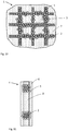
- Fig. 3 is a conductor structure 2a shown, which is formed of an expanded metal.
- Fig. 4 are alternative perforation or Perforations pharmaceutical (round perforation, angular perforation) in a metal foil 2b shown.
- Perforations or Perforations round perforation, angular perforation
- other hole or slit images can be provided, which can be tailored to the desired properties of the lithium anode.
- FIGS. 5 and 6 show an open fabric structure 2c, which is formed from round wires 2 'and which are optionally conductively joined together at their points of contact (eg welded, soldered, pressed).
- round wire cross-sections instead of the illustrated round wire cross-sections, other cross-sectional geometries can be used. It is thus possible to use oval or band-shaped conductors instead of the wires.
- Fig. 7 shows a wire-tile structure 2d, in whose cavities the anode active material can be introduced.
- Fig. 8 shows a knitting or knitting structure 2e, in which also by selecting a special effect mesh 3 with three-dimensional expansion can be realized.
- the properties of a lithium anode 1 embodied in this way can be determined in particular by the geometry of the conductor structure 2, i. by the extent of the current-conducting regions (thickness and width) and by the size and geometry of the open cavities in which the anode active material is arranged.
- the amount of anode active material can also be controlled, so that corresponding free volume 7 is available, which accommodates the expansion of the anode active material 5 (of the silicon material) during the intercalation.
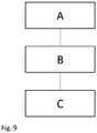
- Fig. 9 shows the sequence of a method according to the invention for producing a lithium anode according to the first embodiment.
- the method comprises the step A - Provision of a current collector layer 4, which is formed like a grid with an open cavities 3 defining conductor structure 2, Step B - arranging anode active material 5 in the cavities 3 between the conductor pattern 2 and Step C - Coating of the current discharge layer 4 with a lithium-conductive material 6, which may optionally also have storage properties.
- step A optionally comprises the provision, production and / or preparation of the conductor structure 2 by a joining method and / or a mechanical machining method.
- Typical joining methods are welding, pressing, soldering and possibly also gluing.
- Typical mechanical processing methods are stamping or cutting processes, with the help of which the cavities are produced from a metal foil or a metal sheet, but also knitting, weaving or other arrangement processes in which current-conducting wires are brought into the desired shape and arrangement (cf. , Fig. 5 to 8 ).
- the step B of the method comprises a dipping process with which the anode active material is arranged in the cavities 3 of the conductor structure 2.
- the anode active material can also be filled in the cavities 3 by rolling or brushing.
- Fig. 10 shows a second embodiment of a lithium anode 1, in which the anode active material is arranged differently.
- the lithium anode 1 shown here also comprises a conductor structure 2, which defines open cavities 3 and is an integral part of the current discharge layer 4 (see Fig. 11 ).
- the anode active material (the silicon material) 5 is arranged as a layer on the surface of the conductor structure, so that it surrounds the conductor structure.
- a coating 6 is likewise provided here, as well as a filling 8 of the cavities 3 of the conductor structure.
- Coating 6 and 8 are formed of a lithium ion conductive material, in particular of a carbon material (see above).
- free cavities are provided which allow local expansion of the anode active material during the intercalation.
- the expansion can take place, for example, in the open cavities 3. But it can also be done in microscopically free volume in the filling 8 and in the coating 6, which are each electrically conductively coupled to the anode active material.
- the enveloping coating of the conductor structure 2 with anode active material 5 allows a particularly age-resistant coupling with the conductor structure.
- the volume changes occurring during the intercalation and deintercalation do not cause any local detachment effects from the conductor structure due to the complete cladding or reduce these effects in contrast to even, impermeable conductor structures. Suitable conductor geometries for these conductor structures are the same as described above in connection with FIGS FIGS. 3 to 8 described.
- the step A also includes the above-described provision, manufacture and preparation of the conductor structure by a joining method and / or a mechanical processing method.
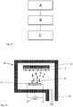
- the arrangement of the anode active material 5 on the conductor structure 2 comprises a physical and / or a chemical process, and in particular one in Fig. 13 illustrated vapor deposition method.
- a conductor structure 2 is arranged in an evacuatable coating chamber 20, which is fixed to a slide 21.
- this slide can be arranged to be movable or rotatable in the chamber 20.
- the silicon material 5 is vaporized via a heater 22 and is reflected in the evacuated via a vacuum pump 23 chamber on the conductor structure 2 down. If desired, the vapor deposition result can be improved by applying a voltage between the anode active material and the conductor structure, so that the vaporized particles 24 can be aimed specifically at the conductor structure.
- Fig. 14 shows a schematic view of an embodiment of a cathode assembly 100, which is suitable for prelithiation of a lithium cell. It comprises a conductor structure 102, which is formed like a grid, which has meshes 103 which define open cavities in the conductor structure. These form a current drain layer 104. In the open cavities (mesh 3), a lithium-based material 105 is arranged. The current collector layer 104 is provided with a coating 106 on both sides, but at least on one side.
- the conductor structure 102 is preferably formed from an aluminum material (eg nickel, gold, platinum, zirconium, titanium, tantalum, various steels and alloys such as Monel, conductive hardened carbon, polymer-supported conductive fiber composites).
- the structure and design of the conductor structure 102 is analogous to that in connection with the lithium anodes 1 described above. It can also be alternative to the in FIGS. 14 and 15 shown grid structure with rectangular conductor cross-section corresponding to the in the FIGS. 3 to 8 be formed variants shown.
- the lithium-based material is formed from a lithium-containing material such as lithium nitrate, lithium oxide, a lithium nitride or even a stabilized lithium powder. It completely or partially fills the cavity defined by the conductor structure and the coating 106 (cf. Figs. 15a and 15b ).
- the lithium-based material 105 in the cavities 103 is used to prelithiate a lithium anode, for example, to compensate for the loss of lithium in forming an SEI layer in the first charging cycles. In this case, a portion of the lithium-based material 105 is consumed and there is formed in the cavity 103 additional free volume (see. Fig. 15b ). However, the degradation of lithium-based material from the cavity does not result in a volume change of the cathode assembly as a whole. This means that there is no change in volume of a correspondingly formed cathode arrangement or a lithium battery provided accordingly with such a cathode arrangement.
- the manufacturing process is analogous to that associated with the Fig. 9 described method for producing a lithium anode.
- the provision of the current conductor layer likewise comprises, as described in connection with the first exemplary embodiment of a lithium anode, the production and the preparation of the conductor structure by the joining methods or mechanical machining methods mentioned there.
- Placing the lithium-based material in the cavity can also be done by a dipping, rolling or brushing method.
- the double-sided coating of the conductor structure 102 makes it possible to combine the cathode arrangement with two corresponding lithium anodes to form a lithium cell.
- FIG. 12 shows a multilayer lithium-ion cell 200 which is multilayered of first electrodes 201 formed as lithium anodes and second electrodes 202 formed as cathode arrays. The electrodes are separated from each other by a separator 203 and solid or liquid for lithium ion transport of an electrolyte material passes through (not shown).
- the first electrode 201 comprises a current collector layer 4 and the second electrode comprises a current collector layer 104.
- the current-carrying layer 4 of the first electrode 201 comprises a conductor pattern 2, which is described in detail above, and whose meshes 3 are filled with a silicon material as the anode active material 5.
- the current collector layer 4 is provided on both sides with a coating 6, which are formed from a lithium ion-conducting material described above, in particular a carbon.
- the cavities 103 of the current drain layer 104 and the conductor structure 102 of the second electrode 202 are filled with a lithium-based material 105, the composition of which is given in connection with the cathode arrangement 100 described above.
- the illustrated lithium ion cell 200 includes two first electrodes (lithium anodes) 201 and three second electrodes (cathode assembly) 202, each arranged alternately are. The outer surfaces are closed with covers 204. The function of such a lithium-ion cell is known per se.
- the lithium-based material 105 in the mesh 103 serves to provide additional lithium, which is incorporated into the anode active material particles 5 and the coating 6 during the formation of an SEI and is no longer available for the actual cell cyclization. This can be used to limit or prevent a loss of capacity.
- this lithium substitute is made volume-neutral from the mesh 103, the geometry of which does not change during this process. This means that the geometry, and in particular the thickness, of such a lithium-ion cell 100 does not change during this process.
- Fig. 17 shows an alternative construction in which the first electrode 201 has a lithium anode according to the second embodiment described above.
- the anode active material 5 is not arranged in the meshes 3, that is to say the open cavities of the conductor structure 2, but as the layer 5 enveloping the conductor structure, into which the lithium ions are likewise stored in a substantially volume-neutral manner during intercalation.
- the meshes 3 are filled with the same material from which the coatings 6 are formed, namely from a, in particular carbonaceous, material for transporting lithium ions.
- Lithium anode (1) according to one of claims 1 to 5, wherein the filling is arranged in the conductor structure such that free volume (7) between the anode active material (5) and the filling is formed and / or the coating (6) on the Stromableiter Anlagen (4) and the filling formed that free volume (7) between the anode active material (5) and the coating (6) is formed.
- Method in which arranging the anode active material (5) on the conductor structure (2) comprises a physical or a chemical or an electrochemical process, in particular a thermal vapor deposition process in an evacuated vapor deposition system (PVD), a chemical vapor deposition from corresponding precursor compounds (CVD) or Electrochemical deposition (plating, fused-salt electrolysis) of the material in a dipping bath with silicon-containing electrolyte carried out as a galvanic cell.
- PVD evacuated vapor deposition system
- CVD chemical vapor deposition from corresponding precursor compounds
- Electrochemical deposition plating, fused-salt electrolysis
- the current conductor layer (4, 104) is formed in the manner of a lattice with a conductor structure (2, 102) defining open cavities (3, 103), the functional material (5, 105) in the cavities (3, 103) between the conductor structure (2, 102) is arranged and the coating (6, 106), the Stromableiter Mrs (4, 104) and the functional material (5, 105) covers.
Landscapes
- Chemical & Material Sciences (AREA)
- Chemical Kinetics & Catalysis (AREA)
- Electrochemistry (AREA)
- General Chemical & Material Sciences (AREA)
- Engineering & Computer Science (AREA)
- Manufacturing & Machinery (AREA)
- Materials Engineering (AREA)
- Composite Materials (AREA)
- Inorganic Chemistry (AREA)
- Dispersion Chemistry (AREA)
- Battery Electrode And Active Subsutance (AREA)
Applications Claiming Priority (1)
| Application Number | Priority Date | Filing Date | Title |
|---|---|---|---|
| DE102018112637.9A DE102018112637A1 (de) | 2018-05-25 | 2018-05-25 | Lithiumanode und Verfahren zu deren Herstellung |
Publications (2)
| Publication Number | Publication Date |
|---|---|
| EP3573141A1 true EP3573141A1 (fr) | 2019-11-27 |
| EP3573141B1 EP3573141B1 (fr) | 2021-12-22 |
Family
ID=66630281
Family Applications (1)
| Application Number | Title | Priority Date | Filing Date |
|---|---|---|---|
| EP19176015.6A Active EP3573141B1 (fr) | 2018-05-25 | 2019-05-22 | Anode au lithium et son procédé de fabrication |
Country Status (4)
| Country | Link |
|---|---|
| US (1) | US11276854B2 (fr) |
| EP (1) | EP3573141B1 (fr) |
| CN (1) | CN110534698B (fr) |
| DE (1) | DE102018112637A1 (fr) |
Families Citing this family (1)
| Publication number | Priority date | Publication date | Assignee | Title |
|---|---|---|---|---|
| JP7281091B2 (ja) * | 2020-02-10 | 2023-05-25 | トヨタ自動車株式会社 | 二次電池の正極材料、および二次電池 |
Citations (14)
| Publication number | Priority date | Publication date | Assignee | Title |
|---|---|---|---|---|
| US626887A (en) | 1899-06-13 | Clay-cutting machine | ||
| US6106978A (en) | 1996-07-31 | 2000-08-22 | Sony Corporation | Non-aqueous electrolyte secondary cell |
| US7736802B1 (en) * | 2004-11-12 | 2010-06-15 | Greatbatch Ltd. | Electrochemical cell current collector comprising solid area for coated film measurements |
| DE102013200749A1 (de) * | 2012-01-23 | 2013-07-25 | GM Global Technology Operations LLC (n.d. Ges. d. Staates Delaware) | Schwundbeständige, hochleistungsfähige elektroden für eine lithium-ionen- batterie |
| US20130309579A1 (en) | 2012-05-16 | 2013-11-21 | Dexmet Corporation | Electrode core plate method and apparatus |
| DE102012212788A1 (de) | 2012-07-20 | 2014-01-23 | Volkswagen Varta Microbattery Forschungsgesellschaft Mbh & Co. Kg | Negative Elektroden für Lithium-Ionen-Batterien und ihre Herstellung |
| DE102012112186A1 (de) | 2012-12-12 | 2014-06-26 | Fraunhofer-Gesellschaft zur Förderung der angewandten Forschung e.V. | Materialverbund, Verfahren zu dessen Herstellung, daraus hergestelltes System und Anwendung desselben |
| DE102013201853A1 (de) * | 2013-02-05 | 2014-08-07 | Robert Bosch Gmbh | Elektrode für ein galvanisches Element und Verfahren zur Herstellung der Elektrode |
| US20140227432A1 (en) | 2011-10-05 | 2014-08-14 | The Regents Of The University Of California | Lithium metal doped electrodes for lithium-ion rechargeable chemistry |
| US20150295246A1 (en) | 2013-09-11 | 2015-10-15 | Lg Chem, Ltd. | Lithium electrode and lithium secondary battery comprising the same |
| US20150364795A1 (en) | 2014-06-12 | 2015-12-17 | Amprius, Inc. | Prelithiation solutions for lithium-ion batteries |
| DE102014226390A1 (de) | 2014-12-18 | 2016-06-23 | Bayerische Motoren Werke Aktiengesellschaft | Kompositanode und diese umfassende Lithiumionenbatterie sowie Verfahren zur Herstellung der Kompositanode |
| CN106058168A (zh) | 2016-02-03 | 2016-10-26 | 万向A二三系统有限公司 | 一种预锂化锂离子二次电池正极材料 |
| DE102015212220A1 (de) | 2015-06-30 | 2017-01-05 | TRUMPF Hüttinger GmbH + Co. KG | Hochfrequenzverstärkeranordnung |
Family Cites Families (11)
| Publication number | Priority date | Publication date | Assignee | Title |
|---|---|---|---|---|
| DE19709783A1 (de) * | 1997-03-10 | 1998-09-17 | Varta Batterie | Laminierte Lithium-Ionen-Zelle und Verfahren zu ihrer Herstellung |
| KR100220449B1 (ko) | 1997-08-16 | 1999-09-15 | 손욱 | 리튬 이온 고분자 이차전지 제조방법 |
| US20060159999A1 (en) * | 2001-07-23 | 2006-07-20 | Kejha Joseph B | Method of automated prismatic electrochemical cells production and method of the cell assembly and construction |
| JP4957680B2 (ja) * | 2008-08-26 | 2012-06-20 | ソニー株式会社 | 非水電解質二次電池用の多孔性保護膜層付き電極、及び非水電解質二次電池 |
| JP5634372B2 (ja) * | 2010-11-04 | 2014-12-03 | 三菱電機株式会社 | 電力貯蔵デバイスセル |
| JP6181948B2 (ja) * | 2012-03-21 | 2017-08-16 | 株式会社半導体エネルギー研究所 | 蓄電装置及び電気機器 |
| JP5724931B2 (ja) * | 2012-04-03 | 2015-05-27 | トヨタ自動車株式会社 | 非水電解質二次電池、及びその製造方法 |
| US9991492B2 (en) * | 2013-11-18 | 2018-06-05 | California Institute Of Technology | Separator enclosures for electrodes and electrochemical cells |
| US9113301B1 (en) | 2014-06-13 | 2015-08-18 | Snapchat, Inc. | Geo-location based event gallery |
| US10276856B2 (en) * | 2015-10-08 | 2019-04-30 | Nanotek Instruments, Inc. | Continuous process for producing electrodes and alkali metal batteries having ultra-high energy densities |
| CN106450434A (zh) * | 2016-12-06 | 2017-02-22 | 龙能科技(苏州)有限责任公司 | 一种高电压高能量密度的锂离子电池 |
-
2018
- 2018-05-25 DE DE102018112637.9A patent/DE102018112637A1/de not_active Withdrawn
-
2019
- 2019-05-22 EP EP19176015.6A patent/EP3573141B1/fr active Active
- 2019-05-24 US US16/421,890 patent/US11276854B2/en active Active
- 2019-05-27 CN CN201910444568.5A patent/CN110534698B/zh active Active
Patent Citations (14)
| Publication number | Priority date | Publication date | Assignee | Title |
|---|---|---|---|---|
| US626887A (en) | 1899-06-13 | Clay-cutting machine | ||
| US6106978A (en) | 1996-07-31 | 2000-08-22 | Sony Corporation | Non-aqueous electrolyte secondary cell |
| US7736802B1 (en) * | 2004-11-12 | 2010-06-15 | Greatbatch Ltd. | Electrochemical cell current collector comprising solid area for coated film measurements |
| US20140227432A1 (en) | 2011-10-05 | 2014-08-14 | The Regents Of The University Of California | Lithium metal doped electrodes for lithium-ion rechargeable chemistry |
| DE102013200749A1 (de) * | 2012-01-23 | 2013-07-25 | GM Global Technology Operations LLC (n.d. Ges. d. Staates Delaware) | Schwundbeständige, hochleistungsfähige elektroden für eine lithium-ionen- batterie |
| US20130309579A1 (en) | 2012-05-16 | 2013-11-21 | Dexmet Corporation | Electrode core plate method and apparatus |
| DE102012212788A1 (de) | 2012-07-20 | 2014-01-23 | Volkswagen Varta Microbattery Forschungsgesellschaft Mbh & Co. Kg | Negative Elektroden für Lithium-Ionen-Batterien und ihre Herstellung |
| DE102012112186A1 (de) | 2012-12-12 | 2014-06-26 | Fraunhofer-Gesellschaft zur Förderung der angewandten Forschung e.V. | Materialverbund, Verfahren zu dessen Herstellung, daraus hergestelltes System und Anwendung desselben |
| DE102013201853A1 (de) * | 2013-02-05 | 2014-08-07 | Robert Bosch Gmbh | Elektrode für ein galvanisches Element und Verfahren zur Herstellung der Elektrode |
| US20150295246A1 (en) | 2013-09-11 | 2015-10-15 | Lg Chem, Ltd. | Lithium electrode and lithium secondary battery comprising the same |
| US20150364795A1 (en) | 2014-06-12 | 2015-12-17 | Amprius, Inc. | Prelithiation solutions for lithium-ion batteries |
| DE102014226390A1 (de) | 2014-12-18 | 2016-06-23 | Bayerische Motoren Werke Aktiengesellschaft | Kompositanode und diese umfassende Lithiumionenbatterie sowie Verfahren zur Herstellung der Kompositanode |
| DE102015212220A1 (de) | 2015-06-30 | 2017-01-05 | TRUMPF Hüttinger GmbH + Co. KG | Hochfrequenzverstärkeranordnung |
| CN106058168A (zh) | 2016-02-03 | 2016-10-26 | 万向A二三系统有限公司 | 一种预锂化锂离子二次电池正极材料 |
Also Published As
| Publication number | Publication date |
|---|---|
| CN110534698A (zh) | 2019-12-03 |
| EP3573141B1 (fr) | 2021-12-22 |
| CN110534698B (zh) | 2023-12-12 |
| US20190363350A1 (en) | 2019-11-28 |
| US11276854B2 (en) | 2022-03-15 |
| DE102018112637A1 (de) | 2019-11-28 |
Similar Documents
| Publication | Publication Date | Title |
|---|---|---|
| EP2517297B1 (fr) | Pile au lithium présentant une structure de cathode améliorée et procédé de fabrication associé | |
| EP3573144B1 (fr) | Cellule lithium-ion et son procédé de fabrication | |
| WO2022111932A1 (fr) | Élément de stockage d'énergie à boîtier prismatique | |
| EP3573141B1 (fr) | Anode au lithium et son procédé de fabrication | |
| EP3573142A1 (fr) | Dispositif de cathode et son procédé de fabrication | |
| DE102016217383A1 (de) | Verfahren zur Herstellung von Elektroden mit verbesserter Stromsammlerstruktur | |
| EP3573143B1 (fr) | Anode au lithium et son procédé de fabrication | |
| DE102022106386A1 (de) | Verfahren und vorrichtung zur herstellung einer elektrode für eine batterie | |
| WO2022058342A1 (fr) | Élément lithium-ion à haute densité d'énergie spécifique | |
| EP4143903A1 (fr) | Pile électrochimique au lithium-ion secondaire | |
| WO2014121978A1 (fr) | Electrode pour un element galvanique et procédé de fabrication de cette electrode | |
| EP3742526B1 (fr) | Élément électrochimique et son procédé de fabrication | |
| DE102021211680B4 (de) | Elektrode für eine Lithiumionenzelle, Lithiumionenzelle, Verfahren zum Herstellen einer Elektrode für eine Lithiumionenzelle | |
| DE102021109245A1 (de) | Komposit-elektrodenmaterialien und verfahren zu deren herstellung | |
| WO2023202987A1 (fr) | Cellule de stockage d'énergie comprenant un ensemble électrode-séparateur enroulé et son procédé de production | |
| WO2023222326A1 (fr) | Batterie au lithium comprenant une anode métallique au lithium avec un conducteur de courant poreux | |
| DE102022106294A1 (de) | Verfahren und vorrichtung zur herstellung einer elektrode für eine batterie | |
| DE102022104964A1 (de) | Verfahren zur Herstellung einer Kombination einer Elektrode und eines Festelektrolyten für eine Batteriezelle | |
| DE102018217756A1 (de) | Verfahren zur Herstellung einer Elektrodeneinheit für eine Batteriezelle und Batteriezelle | |
| WO2016062512A1 (fr) | Cellule galvanique avec séparation robuste des cathode et anode | |
| DE102017217011A1 (de) | Galvanisches Element und Verfahren zu dessen Herstellung | |
| DE102015102088A1 (de) | Beschichtete Elektroden für Lithiumbatterien | |
| DE102004018350A1 (de) | Galvanisches Element |
Legal Events
| Date | Code | Title | Description |
|---|---|---|---|
| PUAI | Public reference made under article 153(3) epc to a published international application that has entered the european phase |
Free format text: ORIGINAL CODE: 0009012 |
|
| STAA | Information on the status of an ep patent application or granted ep patent |
Free format text: STATUS: THE APPLICATION HAS BEEN PUBLISHED |
|
| AK | Designated contracting states |
Kind code of ref document: A1 Designated state(s): AL AT BE BG CH CY CZ DE DK EE ES FI FR GB GR HR HU IE IS IT LI LT LU LV MC MK MT NL NO PL PT RO RS SE SI SK SM TR |
|
| AX | Request for extension of the european patent |
Extension state: BA ME |
|
| STAA | Information on the status of an ep patent application or granted ep patent |
Free format text: STATUS: REQUEST FOR EXAMINATION WAS MADE |
|
| 17P | Request for examination filed |
Effective date: 20200527 |
|
| RBV | Designated contracting states (corrected) |
Designated state(s): AL AT BE BG CH CY CZ DE DK EE ES FI FR GB GR HR HU IE IS IT LI LT LU LV MC MK MT NL NO PL PT RO RS SE SI SK SM TR |
|
| GRAP | Despatch of communication of intention to grant a patent |
Free format text: ORIGINAL CODE: EPIDOSNIGR1 |
|
| STAA | Information on the status of an ep patent application or granted ep patent |
Free format text: STATUS: GRANT OF PATENT IS INTENDED |
|
| INTG | Intention to grant announced |
Effective date: 20210903 |
|
| GRAS | Grant fee paid |
Free format text: ORIGINAL CODE: EPIDOSNIGR3 |
|
| GRAA | (expected) grant |
Free format text: ORIGINAL CODE: 0009210 |
|
| STAA | Information on the status of an ep patent application or granted ep patent |
Free format text: STATUS: THE PATENT HAS BEEN GRANTED |
|
| AK | Designated contracting states |
Kind code of ref document: B1 Designated state(s): AL AT BE BG CH CY CZ DE DK EE ES FI FR GB GR HR HU IE IS IT LI LT LU LV MC MK MT NL NO PL PT RO RS SE SI SK SM TR |
|
| REG | Reference to a national code |
Ref country code: GB Ref legal event code: FG4D Free format text: NOT ENGLISH |
|
| REG | Reference to a national code |
Ref country code: CH Ref legal event code: EP |
|
| REG | Reference to a national code |
Ref country code: DE Ref legal event code: R096 Ref document number: 502019003037 Country of ref document: DE |
|
| REG | Reference to a national code |
Ref country code: AT Ref legal event code: REF Ref document number: 1457652 Country of ref document: AT Kind code of ref document: T Effective date: 20220115 |
|
| REG | Reference to a national code |
Ref country code: IE Ref legal event code: FG4D Free format text: LANGUAGE OF EP DOCUMENT: GERMAN |
|
| REG | Reference to a national code |
Ref country code: LT Ref legal event code: MG9D |
|
| PG25 | Lapsed in a contracting state [announced via postgrant information from national office to epo] |
Ref country code: RS Free format text: LAPSE BECAUSE OF FAILURE TO SUBMIT A TRANSLATION OF THE DESCRIPTION OR TO PAY THE FEE WITHIN THE PRESCRIBED TIME-LIMIT Effective date: 20211222 Ref country code: LT Free format text: LAPSE BECAUSE OF FAILURE TO SUBMIT A TRANSLATION OF THE DESCRIPTION OR TO PAY THE FEE WITHIN THE PRESCRIBED TIME-LIMIT Effective date: 20211222 Ref country code: FI Free format text: LAPSE BECAUSE OF FAILURE TO SUBMIT A TRANSLATION OF THE DESCRIPTION OR TO PAY THE FEE WITHIN THE PRESCRIBED TIME-LIMIT Effective date: 20211222 Ref country code: BG Free format text: LAPSE BECAUSE OF FAILURE TO SUBMIT A TRANSLATION OF THE DESCRIPTION OR TO PAY THE FEE WITHIN THE PRESCRIBED TIME-LIMIT Effective date: 20220322 |
|
| REG | Reference to a national code |
Ref country code: NL Ref legal event code: MP Effective date: 20211222 |
|
| PG25 | Lapsed in a contracting state [announced via postgrant information from national office to epo] |
Ref country code: SE Free format text: LAPSE BECAUSE OF FAILURE TO SUBMIT A TRANSLATION OF THE DESCRIPTION OR TO PAY THE FEE WITHIN THE PRESCRIBED TIME-LIMIT Effective date: 20211222 Ref country code: NO Free format text: LAPSE BECAUSE OF FAILURE TO SUBMIT A TRANSLATION OF THE DESCRIPTION OR TO PAY THE FEE WITHIN THE PRESCRIBED TIME-LIMIT Effective date: 20220322 Ref country code: LV Free format text: LAPSE BECAUSE OF FAILURE TO SUBMIT A TRANSLATION OF THE DESCRIPTION OR TO PAY THE FEE WITHIN THE PRESCRIBED TIME-LIMIT Effective date: 20211222 Ref country code: HR Free format text: LAPSE BECAUSE OF FAILURE TO SUBMIT A TRANSLATION OF THE DESCRIPTION OR TO PAY THE FEE WITHIN THE PRESCRIBED TIME-LIMIT Effective date: 20211222 Ref country code: GR Free format text: LAPSE BECAUSE OF FAILURE TO SUBMIT A TRANSLATION OF THE DESCRIPTION OR TO PAY THE FEE WITHIN THE PRESCRIBED TIME-LIMIT Effective date: 20220323 |
|
| PG25 | Lapsed in a contracting state [announced via postgrant information from national office to epo] |
Ref country code: NL Free format text: LAPSE BECAUSE OF FAILURE TO SUBMIT A TRANSLATION OF THE DESCRIPTION OR TO PAY THE FEE WITHIN THE PRESCRIBED TIME-LIMIT Effective date: 20211222 |
|
| PG25 | Lapsed in a contracting state [announced via postgrant information from national office to epo] |
Ref country code: SM Free format text: LAPSE BECAUSE OF FAILURE TO SUBMIT A TRANSLATION OF THE DESCRIPTION OR TO PAY THE FEE WITHIN THE PRESCRIBED TIME-LIMIT Effective date: 20211222 Ref country code: SK Free format text: LAPSE BECAUSE OF FAILURE TO SUBMIT A TRANSLATION OF THE DESCRIPTION OR TO PAY THE FEE WITHIN THE PRESCRIBED TIME-LIMIT Effective date: 20211222 Ref country code: RO Free format text: LAPSE BECAUSE OF FAILURE TO SUBMIT A TRANSLATION OF THE DESCRIPTION OR TO PAY THE FEE WITHIN THE PRESCRIBED TIME-LIMIT Effective date: 20211222 Ref country code: PT Free format text: LAPSE BECAUSE OF FAILURE TO SUBMIT A TRANSLATION OF THE DESCRIPTION OR TO PAY THE FEE WITHIN THE PRESCRIBED TIME-LIMIT Effective date: 20220422 Ref country code: ES Free format text: LAPSE BECAUSE OF FAILURE TO SUBMIT A TRANSLATION OF THE DESCRIPTION OR TO PAY THE FEE WITHIN THE PRESCRIBED TIME-LIMIT Effective date: 20211222 Ref country code: EE Free format text: LAPSE BECAUSE OF FAILURE TO SUBMIT A TRANSLATION OF THE DESCRIPTION OR TO PAY THE FEE WITHIN THE PRESCRIBED TIME-LIMIT Effective date: 20211222 Ref country code: CZ Free format text: LAPSE BECAUSE OF FAILURE TO SUBMIT A TRANSLATION OF THE DESCRIPTION OR TO PAY THE FEE WITHIN THE PRESCRIBED TIME-LIMIT Effective date: 20211222 |
|
| PG25 | Lapsed in a contracting state [announced via postgrant information from national office to epo] |
Ref country code: PL Free format text: LAPSE BECAUSE OF FAILURE TO SUBMIT A TRANSLATION OF THE DESCRIPTION OR TO PAY THE FEE WITHIN THE PRESCRIBED TIME-LIMIT Effective date: 20211222 |
|
| REG | Reference to a national code |
Ref country code: DE Ref legal event code: R097 Ref document number: 502019003037 Country of ref document: DE |
|
| PG25 | Lapsed in a contracting state [announced via postgrant information from national office to epo] |
Ref country code: IS Free format text: LAPSE BECAUSE OF FAILURE TO SUBMIT A TRANSLATION OF THE DESCRIPTION OR TO PAY THE FEE WITHIN THE PRESCRIBED TIME-LIMIT Effective date: 20220422 |
|
| PLBE | No opposition filed within time limit |
Free format text: ORIGINAL CODE: 0009261 |
|
| STAA | Information on the status of an ep patent application or granted ep patent |
Free format text: STATUS: NO OPPOSITION FILED WITHIN TIME LIMIT |
|
| PG25 | Lapsed in a contracting state [announced via postgrant information from national office to epo] |
Ref country code: DK Free format text: LAPSE BECAUSE OF FAILURE TO SUBMIT A TRANSLATION OF THE DESCRIPTION OR TO PAY THE FEE WITHIN THE PRESCRIBED TIME-LIMIT Effective date: 20211222 Ref country code: AL Free format text: LAPSE BECAUSE OF FAILURE TO SUBMIT A TRANSLATION OF THE DESCRIPTION OR TO PAY THE FEE WITHIN THE PRESCRIBED TIME-LIMIT Effective date: 20211222 |
|
| 26N | No opposition filed |
Effective date: 20220923 |
|
| REG | Reference to a national code |
Ref country code: CH Ref legal event code: PL |
|
| REG | Reference to a national code |
Ref country code: BE Ref legal event code: MM Effective date: 20220531 |
|
| PG25 | Lapsed in a contracting state [announced via postgrant information from national office to epo] |
Ref country code: MC Free format text: LAPSE BECAUSE OF FAILURE TO SUBMIT A TRANSLATION OF THE DESCRIPTION OR TO PAY THE FEE WITHIN THE PRESCRIBED TIME-LIMIT Effective date: 20211222 Ref country code: LU Free format text: LAPSE BECAUSE OF NON-PAYMENT OF DUE FEES Effective date: 20220522 Ref country code: LI Free format text: LAPSE BECAUSE OF NON-PAYMENT OF DUE FEES Effective date: 20220531 Ref country code: CH Free format text: LAPSE BECAUSE OF NON-PAYMENT OF DUE FEES Effective date: 20220531 |
|
| PG25 | Lapsed in a contracting state [announced via postgrant information from national office to epo] |
Ref country code: SI Free format text: LAPSE BECAUSE OF FAILURE TO SUBMIT A TRANSLATION OF THE DESCRIPTION OR TO PAY THE FEE WITHIN THE PRESCRIBED TIME-LIMIT Effective date: 20211222 |
|
| PG25 | Lapsed in a contracting state [announced via postgrant information from national office to epo] |
Ref country code: IE Free format text: LAPSE BECAUSE OF NON-PAYMENT OF DUE FEES Effective date: 20220522 |
|
| PG25 | Lapsed in a contracting state [announced via postgrant information from national office to epo] |
Ref country code: IT Free format text: LAPSE BECAUSE OF FAILURE TO SUBMIT A TRANSLATION OF THE DESCRIPTION OR TO PAY THE FEE WITHIN THE PRESCRIBED TIME-LIMIT Effective date: 20211222 Ref country code: BE Free format text: LAPSE BECAUSE OF NON-PAYMENT OF DUE FEES Effective date: 20220531 |
|
| P01 | Opt-out of the competence of the unified patent court (upc) registered |
Effective date: 20230523 |
|
| PGFP | Annual fee paid to national office [announced via postgrant information from national office to epo] |
Ref country code: FR Payment date: 20230523 Year of fee payment: 5 Ref country code: DE Payment date: 20230531 Year of fee payment: 5 |
|
| PGFP | Annual fee paid to national office [announced via postgrant information from national office to epo] |
Ref country code: GB Payment date: 20230523 Year of fee payment: 5 |
|
| PG25 | Lapsed in a contracting state [announced via postgrant information from national office to epo] |
Ref country code: HU Free format text: LAPSE BECAUSE OF FAILURE TO SUBMIT A TRANSLATION OF THE DESCRIPTION OR TO PAY THE FEE WITHIN THE PRESCRIBED TIME-LIMIT; INVALID AB INITIO Effective date: 20190522 |
|
| PG25 | Lapsed in a contracting state [announced via postgrant information from national office to epo] |
Ref country code: MK Free format text: LAPSE BECAUSE OF FAILURE TO SUBMIT A TRANSLATION OF THE DESCRIPTION OR TO PAY THE FEE WITHIN THE PRESCRIBED TIME-LIMIT Effective date: 20211222 Ref country code: CY Free format text: LAPSE BECAUSE OF FAILURE TO SUBMIT A TRANSLATION OF THE DESCRIPTION OR TO PAY THE FEE WITHIN THE PRESCRIBED TIME-LIMIT Effective date: 20211222 |