EP3572803B1 - Garnsensor zum optischen erfassen eines in seiner längsrichtung bewegten garns - Google Patents
Garnsensor zum optischen erfassen eines in seiner längsrichtung bewegten garns Download PDFInfo
- Publication number
- EP3572803B1 EP3572803B1 EP19172499.6A EP19172499A EP3572803B1 EP 3572803 B1 EP3572803 B1 EP 3572803B1 EP 19172499 A EP19172499 A EP 19172499A EP 3572803 B1 EP3572803 B1 EP 3572803B1
- Authority
- EP
- European Patent Office
- Prior art keywords
- yarn
- light
- guiding element
- sensor
- detector
- Prior art date
- Legal status (The legal status is an assumption and is not a legal conclusion. Google has not performed a legal analysis and makes no representation as to the accuracy of the status listed.)
- Active
Links
Images
Classifications
-
- B—PERFORMING OPERATIONS; TRANSPORTING
- B65—CONVEYING; PACKING; STORING; HANDLING THIN OR FILAMENTARY MATERIAL
- B65H—HANDLING THIN OR FILAMENTARY MATERIAL, e.g. SHEETS, WEBS, CABLES
- B65H63/00—Warning or safety devices, e.g. automatic fault detectors, stop-motions ; Quality control of the package
- B65H63/06—Warning or safety devices, e.g. automatic fault detectors, stop-motions ; Quality control of the package responsive to presence of irregularities in running material, e.g. for severing the material at irregularities ; Control of the correct working of the yarn cleaner
-
- D—TEXTILES; PAPER
- D01—NATURAL OR MAN-MADE THREADS OR FIBRES; SPINNING
- D01H—SPINNING OR TWISTING
- D01H13/00—Other common constructional features, details or accessories
- D01H13/14—Warning or safety devices, e.g. automatic fault detectors, stop motions ; Monitoring the entanglement of slivers in drafting arrangements
- D01H13/16—Warning or safety devices, e.g. automatic fault detectors, stop motions ; Monitoring the entanglement of slivers in drafting arrangements responsive to reduction in material tension, failure of supply, or breakage, of material
- D01H13/1616—Warning or safety devices, e.g. automatic fault detectors, stop motions ; Monitoring the entanglement of slivers in drafting arrangements responsive to reduction in material tension, failure of supply, or breakage, of material characterised by the detector
- D01H13/1633—Electronic actuators
- D01H13/165—Photo-electric sensing means
-
- D—TEXTILES; PAPER
- D01—NATURAL OR MAN-MADE THREADS OR FIBRES; SPINNING
- D01H—SPINNING OR TWISTING
- D01H13/00—Other common constructional features, details or accessories
- D01H13/14—Warning or safety devices, e.g. automatic fault detectors, stop motions ; Monitoring the entanglement of slivers in drafting arrangements
- D01H13/22—Warning or safety devices, e.g. automatic fault detectors, stop motions ; Monitoring the entanglement of slivers in drafting arrangements responsive to presence of irregularities in running material
-
- D—TEXTILES; PAPER
- D01—NATURAL OR MAN-MADE THREADS OR FIBRES; SPINNING
- D01H—SPINNING OR TWISTING
- D01H13/00—Other common constructional features, details or accessories
- D01H13/26—Arrangements facilitating the inspection or testing of yarns or the like in connection with spinning or twisting
-
- D—TEXTILES; PAPER
- D01—NATURAL OR MAN-MADE THREADS OR FIBRES; SPINNING
- D01H—SPINNING OR TWISTING
- D01H13/00—Other common constructional features, details or accessories
- D01H13/32—Counting, measuring, recording or registering devices
-
- D—TEXTILES; PAPER
- D06—TREATMENT OF TEXTILES OR THE LIKE; LAUNDERING; FLEXIBLE MATERIALS NOT OTHERWISE PROVIDED FOR
- D06H—MARKING, INSPECTING, SEAMING OR SEVERING TEXTILE MATERIALS
- D06H3/00—Inspecting textile materials
- D06H3/08—Inspecting textile materials by photo-electric or television means
-
- G—PHYSICS
- G01—MEASURING; TESTING
- G01B—MEASURING LENGTH, THICKNESS OR SIMILAR LINEAR DIMENSIONS; MEASURING ANGLES; MEASURING AREAS; MEASURING IRREGULARITIES OF SURFACES OR CONTOURS
- G01B11/00—Measuring arrangements characterised by the use of optical techniques
- G01B11/08—Measuring arrangements characterised by the use of optical techniques for measuring diameters
- G01B11/10—Measuring arrangements characterised by the use of optical techniques for measuring diameters of objects while moving
- G01B11/105—Measuring arrangements characterised by the use of optical techniques for measuring diameters of objects while moving using photoelectric detection means
-
- G—PHYSICS
- G01—MEASURING; TESTING
- G01N—INVESTIGATING OR ANALYSING MATERIALS BY DETERMINING THEIR CHEMICAL OR PHYSICAL PROPERTIES
- G01N21/00—Investigating or analysing materials by the use of optical means, i.e. using sub-millimetre waves, infrared, visible or ultraviolet light
- G01N21/84—Systems specially adapted for particular applications
- G01N21/88—Investigating the presence of flaws or contamination
- G01N21/89—Investigating the presence of flaws or contamination in moving material, e.g. running paper or textiles
- G01N21/8901—Optical details; Scanning details
-
- G—PHYSICS
- G01—MEASURING; TESTING
- G01N—INVESTIGATING OR ANALYSING MATERIALS BY DETERMINING THEIR CHEMICAL OR PHYSICAL PROPERTIES
- G01N21/00—Investigating or analysing materials by the use of optical means, i.e. using sub-millimetre waves, infrared, visible or ultraviolet light
- G01N21/84—Systems specially adapted for particular applications
- G01N21/88—Investigating the presence of flaws or contamination
- G01N21/89—Investigating the presence of flaws or contamination in moving material, e.g. running paper or textiles
- G01N21/8914—Investigating the presence of flaws or contamination in moving material, e.g. running paper or textiles characterised by the material examined
-
- G—PHYSICS
- G01—MEASURING; TESTING
- G01N—INVESTIGATING OR ANALYSING MATERIALS BY DETERMINING THEIR CHEMICAL OR PHYSICAL PROPERTIES
- G01N21/00—Investigating or analysing materials by the use of optical means, i.e. using sub-millimetre waves, infrared, visible or ultraviolet light
- G01N21/84—Systems specially adapted for particular applications
- G01N21/88—Investigating the presence of flaws or contamination
- G01N21/89—Investigating the presence of flaws or contamination in moving material, e.g. running paper or textiles
- G01N21/8914—Investigating the presence of flaws or contamination in moving material, e.g. running paper or textiles characterised by the material examined
- G01N21/8915—Investigating the presence of flaws or contamination in moving material, e.g. running paper or textiles characterised by the material examined non-woven textile material
-
- G—PHYSICS
- G01—MEASURING; TESTING
- G01N—INVESTIGATING OR ANALYSING MATERIALS BY DETERMINING THEIR CHEMICAL OR PHYSICAL PROPERTIES
- G01N33/00—Investigating or analysing materials by specific methods not covered by groups G01N1/00 - G01N31/00
- G01N33/36—Textiles
-
- G—PHYSICS
- G01—MEASURING; TESTING
- G01N—INVESTIGATING OR ANALYSING MATERIALS BY DETERMINING THEIR CHEMICAL OR PHYSICAL PROPERTIES
- G01N33/00—Investigating or analysing materials by specific methods not covered by groups G01N1/00 - G01N31/00
- G01N33/36—Textiles
- G01N33/365—Filiform textiles, e.g. yarns
-
- G—PHYSICS
- G01—MEASURING; TESTING
- G01N—INVESTIGATING OR ANALYSING MATERIALS BY DETERMINING THEIR CHEMICAL OR PHYSICAL PROPERTIES
- G01N21/00—Investigating or analysing materials by the use of optical means, i.e. using sub-millimetre waves, infrared, visible or ultraviolet light
- G01N21/17—Systems in which incident light is modified in accordance with the properties of the material investigated
- G01N21/55—Specular reflectivity
- G01N21/552—Attenuated total reflection
Definitions
- the subject matter of the invention relates to a yarn sensor for optically detecting a yarn moving in its longitudinal direction.
- the invention also relates to a textile machine with the yarn sensor and a method for operating a yarn sensor.
- Yarn sensors are used on textile machines such as spinning machines and winding machines. They are used to monitor the yarn and/or the yarn quality. Such yarn sensors have a light source and a detector, which provides an optically operating monitoring system to ensure appropriate signal detection. The contactless monitoring and scanning of the yarn is carried out separately for each work station. The use of a yarn monitoring system is of particular importance for the textile machine and therefore also for the quality of the yarn.
- the yarn monitoring system provides information about the presence of the yarn.
- the yarn sensor forms a so-called thread monitor.
- Yarn sensors are also known that monitor the yarn thickness or yarn quality.
- the presence of the yarn can be monitored or the quality of the yarn can be determined.
- the diameter of the yarn is determined and impurities, especially foreign fibers, are detected.
- the US 4,490,618 discloses a device for analyzing a surface of a textile fabric with a prism with a first and a second refracting surface and a back surface.
- a refracting surface is designed to come into contact with the textile fabric under predetermined pressure.
- a woven or knitted fabric is measured using a total reflection measurement method.
- the yarn is guided contactlessly within a measuring gap. Dust, dirt particles and finishing agents are guided to the yarn sensor by the yarn and the air carried in with the yarn. These particles settle on the Sensor surfaces of the yarn sensor, which can lead to a level of contamination that leads to significant distortions of measured values.
- the DE 41 22 305 A1 discloses a device for optoelectrical scanning of a thread with a thread guide element in order to avoid fluttering movements of the thread.
- the optoelectrical scanning uses a reflection sensor, wherein a sensor is provided which has a photodiode with a collecting lens attached as the light-emitting component and a light guide arranged centrally in the collecting lens with an associated photodetector as the light-receiving component.
- EP 1 655 599 B1 A yarn sensor for optically scanning a yarn moving in its longitudinal direction in a measuring gap is known, in which essentially only light from a light source reflected by the yarn reaches two receivers for reflected light. This reduces external influences, e.g. from fibers or dust.
- the aim of the present invention is to increase the reliability of the yarn sensor.
- a yarn sensor for optically detecting a yarn moving in its longitudinal direction, comprising a light source, a detector and a light guide means for guiding the light emitted by the light source.
- Yarn guide means are provided to bring a yarn into contact with the outer surface of the light guide means.
- the light guide means are designed such that when no yarn is in contact with the outer surface of the light guide means, total reflection is achieved and that at least part of the light is coupled out of the light guide means by contact with the yarn.
- the detector is arranged and designed to detect the light which is coupled out of the light guide means or to evaluate the reduced intensity in the totally reflected beam.
- the yarn sensor according to the invention is based on the effect of frustrated total internal reflection (FTIR).
- FTIR frustrated total internal reflection
- Total reflection takes place at an interface between two light-absorbing media with different propagation speeds of the light when the angle of incidence exceeds a certain value, the so-called critical angle of total reflection.
- the optical density of the air is significantly lower than the optical density of the yarn. Frustrated total reflection occurs when the yarn comes into contact with a contact surface between the yarn and the outer surface of the light guide, since the refractive index of the yarn is greater than the refractive index of air.
- the light that emerges from the light guide in the contact area between the yarn and the outer surface of the light guide is scattered by the yarn.
- the scattered light propagates out of the light guide.
- This scattered light can be detected directly or indirectly by the detector, which enables the yarn lying on the outer surface to be detected. Or, to put it another way, the influence of the yarn on the light emitted by the light source is detected. There are basically two ways to do this, which can be used alternatively or in conjunction with one another.
- the detector is arranged and designed such that it detects light that is coupled out of the light guiding means by the yarn.
- the detector is arranged and designed such that it detects the remaining light guided by the light guiding means and not coupled out by the yarn.
- the detector detects the scattered light that is coupled out of the light guide means. This is the light that is reflected at the contact surface between the yarn and the outer surface of the light guide means.
- the light guide means it is possible for the light guide means to be suitable and intended to guide the light reflected on the outer surface of the light guide means to the detector.
- the reduced intensity in the totally reflected beam is then evaluated using the detector.
- the intensity in the totally reflected beam is essentially reduced by the scattered light coupled out of the light guide means.
- the inventive design of the optical yarn sensor departs from the previous development of optically operating yarn sensors and takes a completely new path.
- a yarn sensor is provided which is simple in its construction and less sensitive to environmental influences. Because the moving yarn rests against the light guide during operation, the problems of contamination known with known optical yarn sensors are essentially avoided, since the yarn causes a self-cleaning effect in the area of the contact surface with the light guide.
- the area of the light guide adjacent to the contact surface is also cleaned.
- the hairiness of the yarn means that dirt is not only removed from the contact surface between the yarn and the outer surface of the light guide, but also from the area adjacent to the contact surface. This cleaning effect is enhanced by a "chimney effect" as the moving yarn and the boundary layer flow that forms generate a draft.
- the inventive design of the yarn sensor also enables a very compact design, since the structure of the optical system can be minimized to only a very small number of components.
- the yarn sensor according to the invention can be used as a so-called thread monitor.
- the thread monitor provides information about whether a yarn is present or not.
- the intensity of the scattered light that is coupled out of the light guide is proportional to the contact area of the yarn with the outer surface of the light guide.
- the diameter of the yarn can be determined, so that the yarn sensor can also provide information about the quality of the yarn. For example, knots in the yarn can be detected.
- the yarn guide can, for example, contain a guide eyelet in front of and behind the light guide in the direction of the thread.
- the light guide means consists at least partially of a transparent ceramic.
- the use of a ceramic has the advantage that the wear of the light guide means can be kept to a minimum.
- the transparent ceramic can represent an outer layer of a light guide means.
- the transparent ceramic can be coated with a Glass bodies or plastic bodies can be connected, for example, using a transparent adhesive. If a transparent ceramic is glued to a plastic body, for example, it must be ensured that no air pockets are created in the adhesive layer.
- the outer surface of the light guide means is preferably convexly curved. This ensures that the yarn is reliably attached to the outer surface of the light guide means.
- the light guide means has a circular cross-section.
- the light guide means can in particular be designed in the form of a round rod.
- the light source is preferably suitable and intended to emit infrared light.
- the light source can comprise at least one light-emitting diode.
- the detector is in particular a spatially resolving detector. This has, for example, a CCB or CMOS array, a CCD or CMOS line.
- the detector is an active pixel sensor.
- the active pixel sensor has an integrated circuit with a series of pixel sensors. Each pixel sensor can, for example, comprise a photodiode with an active amplifier.
- the light guide means is a component of a yarn guide element.
- a yarn sensor formed in this way has the advantage that the number of components can be reduced.
- a higher monitoring quality in the spinning process can be achieved due to the compact design of the yarn sensor, in particular because the light guide means is a component of a yarn guide element.
- the invention also relates to a textile machine with a yarn sensor according to the invention.
- the invention thus also relates to a method for optically detecting a yarn moving in its longitudinal direction using a light guide.
- a method for optically detecting a yarn moving in its longitudinal direction using a light guide According to the method according to the invention, light is guided through the light guide, whereby if no yarn is in contact with the outer surface of the light guide, total reflection is achieved.
- the yarn is brought into contact with the outer surface of the light guide, so that at least part of the light from the light guide means.
- the light influenced by the yarn is detected. To do this, the light that is decoupled from the light guide means by the yarn can be detected. It is also possible to detect the remaining light that is guided through the light guide means and not decoupled by the yarn.
- the light influenced by the yarn can be evaluated. Diameter deviations and contamination can be detected. The presence of the yarn or thread alone can also be evaluated.
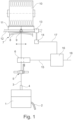
- Fig. 1 shows a schematic diagram of a workstation of a textile machine according to the invention.
- the textile machine is designed as an open-end spinning machine.
- a fiber sliver 2 is fed to a spinning box 1.
- the yarn 3 produced in the spinning box 2 is drawn off via a draw-off tube 4 by means of a draw-off roller pair 5.
- the yarn 3 passes through a yarn sensor 6 according to the invention and is wound up over a bracket 8 by a back and forth movement of a thread guide 9 of a traversing device 7 over a predetermined width to form a cross-wound bobbin 10.
- a friction roller 11 drives the cross-wound bobbin 10.
- the thread guide 9 is arranged on a thread guide rod 12.
- the thread guide rod 12 is moved back and forth by a thread guide gear 13.
- a drive unit 14 is provided to generate the back and forth movement of the thread guide gear 13.
- the yarn sensor 6 for monitoring the running yarn 3 is arranged above the take-off roller pair 5 in the traversing area of the yarn 3. This is not mandatory. It is also possible for the yarn sensor 6 to be arranged upstream of the take-off roller pair 5.
- the arrangement of the yarn sensor 6 is shown here as an example.
- the yarn sensor 6 can be provided at suitable points along the yarn path.
- the yarn sensor 6 is connected to a control device 16 via a signal line 15.
- the control device 16 is connected to the drive unit 14 via a further signal line 17.
- the drive device 14 is preferably an electric motor.
- the control device 16 can be connected to further spinning stations, data processing devices and spinning machines (not shown) via a signal line 18.
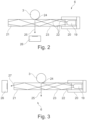
- the yarn sensor 6 has a light source 19.
- the light source 19 is preferably an infrared LED.
- the light source 19 is arranged in a housing 20.
- the housing 19 also serves as a holder for a light guide 21.
- the light guide 21 is designed in the form of a round rod.
- the material of the light guide 21 is preferably a transparent ceramic.
- the reference number 22 designates rays emitted by the light source 19 merely to clarify the principle of the invention.
- the rays 22 are reflected on the outer surface 23.
- the light source 19 and the light guide means 21 are designed such that when no yarn is in contact with the outer surface 23 of the light guide means 21, total reflection is achieved.
- a yarn 3 is shown schematically.
- the yarn 3 lies on the outer surface 23 of the light guide means 21.
- a contact surface 24 lies between the yarn 3 and the outer surface 23.
- the contact of the yarn 3 with the light guide means 21 results in frustrated total reflection in the area of the contact surface 24, since the refractive index of the yarn 3 is greater than the refractive index of the air surrounding the yarn sensor 6.
- the frustrated total reflection causes the light that emerges from the light guide means 21 in the area of the contact surface 24 to be scattered by the yarn.
- the scattered light propagates through the light guide means 21, which is indicated by the beam 25. This scattered light is detected by a detector 26.
- the detector 26 supplies signals that can be fed to the control device 16, for example.
- Fig. 3 shows a second embodiment of a yarn sensor.
- the yarn sensor 6 comprises a light source 19 which is arranged in a housing 20.
- the housing 20 simultaneously serves as a holder for a light guide means 21.
- the yarn 3 rests against an outer surface 23 of the light guide means 21.
- the difference between the embodiment according to Fig. 3 and the embodiment according to Fig. 2 consists in the arrangement of the detector 26 and the associated evaluation methodology. Instead of the scattered light, which is to be indicated by the beam 25, which is coupled out of the light guide means 21, the reduced intensity in the totally reflected beam 27 is evaluated.
- the detector 26 is preferably a pixel sensor, in particular an active pixel sensor.
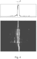
- a snapshot of the scattered light that a detector has recorded is shown. The evaluation of this recording is shown in a diagram. It can be seen that a yarn is attached to the light guide.
- the width B of the detector signal can be used to determine the yarn diameter, since the scattered light is proportional to the yarn diameter at constant thread tension. This also allows thin and thick spots in the yarn to be detected.
Landscapes
- Engineering & Computer Science (AREA)
- Textile Engineering (AREA)
- Chemical & Material Sciences (AREA)
- Health & Medical Sciences (AREA)
- Life Sciences & Earth Sciences (AREA)
- Physics & Mathematics (AREA)
- General Physics & Mathematics (AREA)
- Biochemistry (AREA)
- Analytical Chemistry (AREA)
- Pathology (AREA)
- General Health & Medical Sciences (AREA)
- Immunology (AREA)
- Mechanical Engineering (AREA)
- Food Science & Technology (AREA)
- Medicinal Chemistry (AREA)
- Materials Engineering (AREA)
- Quality & Reliability (AREA)
- Spinning Or Twisting Of Yarns (AREA)
- Filamentary Materials, Packages, And Safety Devices Therefor (AREA)
- Knitting Machines (AREA)
- Looms (AREA)
- Treatment Of Fiber Materials (AREA)
Description
- Der Gegenstand der Erfindung bezieht sich auf einen Garnsensor zum optischen Erfassen eines in seiner Längsrichtung bewegten Garns. Die Erfindung betrifft ebenfalls eine Textilmaschine mit dem Garnsensor und ein Verfahren zum Betreiben eines Garnsensors.
- Garnsensoren werden an Textilmaschinen, wie Spinnmaschinen und Spulmaschinen, eingesetzt. Sie dienen zur Überwachung des Garns und/oder der Garnqualität. Derartige Garnsensoren weisen eine Lichtquelle und einen Detektor auf, wodurch ein optisch arbeitendes Überwachungssystem bereitgestellt wird, um eine entsprechende Signalerfassung zu gewährleisten. Die berührungslose Überwachung und Abtastung des Garns erfolgt für jede Arbeitsstelle getrennt. Die Verwendung eines Garnüberwachungssystems ist für die Textilmaschine und somit auch für die Qualität des Garns von besonderer Bedeutung.
- Das Garnüberwachungssystem liefert eine Information über ein Vorhandensein des Garns. In einem solchen Fall bildet der Garnsensor einen sogenannten Fadenwächter. Es sind auch Garnsensoren bekannt, mittels denen die Garnstärke bzw. Garnqualität überwacht werden.
- Durch das optische Erfassen des Garnes kann also das Vorhandensein des Garnes überwacht oder es kann die Qualität des Garnes ermittelt werden. Zur Ermittlung der Qualität des Garnes werden insbesondere der Durchmesser des Garnes bestimmt und Verunreinigungen, insbesondere Fremdfasern, detektiert.
- Die
US 4,490,618 offenbart eine Vorrichtung zur Analyse einer Oberfläche eines textilen Flächengewebes mit einem Prisma mit einer ersten und einer zweiten brechenden Oberfläche und einer Rückfläche. Eine brechende Oberfläche ist ausgebildet, um unter vorbestimmten Druck mit dem textilen Flächengewebe in Kontakt zu kommen. - Gemäß der
WO 2016/027792A1 wird ein gewebter oder gestrickter Stoff mit einer Totalreflexionsmessmethode gemessen. - Bei den bekannten optischen Garnsensoren wird das Garn innerhalb eines Messspalts berührungslos geführt. Durch das Garn und die mit dem Garn eingeschleppte Luft werden Staub, Schmutzpartikel und Avivagen zu dem Garnsensor geführt. Diese Partikel lagern sich auf den Sensorflächen des Garnsensors ab, wodurch es zu einem Verschmutzungsgrad kommen kann, der zu erheblichen Verfälschungen von Messwerten führt.
- Die
DE 41 22 305 A1 offenbart eine Vorrichtung zur optoelektrischen Abtastung eines Fadens mit einem Fadenführungselement, um Flatterbewegungen des Fadens zu vermeiden. Die optoelektrische Abtastung gebraucht einen Reflexions-Sensor, wobei ein Sensor vorgesehen ist, der als Licht emittierendes Bauelement eine Fotodiode mit vorgesetzter Sammellinse und als Licht empfangendes Bauelement einen zentral in der Sammellinse angeordneten Lichtleiter mit zugeordnetem Fotodetektor aufweist. - Auch ist das Verschmutzungsproblem bei Garnsensoren bereits erkannt worden. Durch die
EP 1 655 599 B1 ist ein Garnsensor zum optischen Abtasten eines in seiner Längsrichtung in einem Messspalt bewegten Garns bekannt, bei dem im Wesentlichen lediglich vom Garn reflektiertes Licht einer Lichtquelle zwei Empfänger für reflektiertes Licht erreicht. Hierdurch lassen sich Fremdeinflüsse, bspw. durch Fasern oder Staub, verringern. - Durch die Druckschrift
WO 93/12028 A1 - Hiervon ausgehend liegt der vorliegenden Erfindung die Zielsetzung zugrunde, die Zuverlässigkeit des Garnsensors zu erhöhen.
- Diese Aufgabe wird erfindungsgemäß durch einen Garnsensor mit den Merkmalen des Anspruchs 1 gelöst. Vorteilhafte Weiterbildungen und Ausgestaltungen des erfindungsgemäßen Garnsensors sind Gegenstand der abhängigen Ansprüche.
- Die in den abhängig formulierten Ansprüchen einzeln aufgeführten Merkmale können in beliebiger, technologisch sinnvoller Weise miteinander kombiniert werden und weitere Ausgestaltungen der Erfindung definieren. Darüber hinaus werden die in den Ansprüchen angegebenen Merkmale in der Beschreibung näher präzisiert und erläutert, wobei weitere bevorzugte Ausführungsbeispiele der Erfindung dargestellt werden.
- Erfindungsgemäß wird ein Garnsensor zum optischen Erfassen eines in seiner Längsrichtung bewegten Garns mit einer Lichtquelle, einem Detektor und einem Lichtführungsmittel zur Führung des von der Lichtquelle ausgesandten Lichtes vorgeschlagen. Es sind Garnführungsmittel vorhanden, um ein Garn mit der Außenfläche des Lichtführungsmittels in Kontakt zu bringen. Die Lichtführungsmittel sind so ausgebildet, dass wenn kein Garn an der Außenfläche des Lichtführungsmittels anliegt, eine Totalreflektion erreicht wird und dass durch Kontakt mit dem Garn zumindest ein Teil des Lichtes aus dem Lichtführungsmittel ausgekoppelt wird.
- Der Detektor ist so angeordnet und ausgebildet, dass er das Licht, welches aus dem Lichtführungsmittel ausgekoppelt wird, detektiert oder die verminderte Intensität im totalreflektierten Strahl bewertet.
- Der erfindungsgemäße Garnsensor basiert dabei auf dem Effekt der frustrierten Totalreflektion (frustrated total internal reflection, FTIR). Eine Totalreflektion findet an einer Grenzfläche zweier Licht absorbierender Medien mit unterschiedlich großer Ausbreitungsgeschwindigkeit des Lichts statt, wenn der Einfallswinkel einen bestimmten Wert, den sogenannten Grenzwinkel der Totalreflektion, überschreitet. Die optische Dichte der Luft ist wesentlich geringer als die optische Dichte des Garns. Durch den Kontakt des Garns an einer Kontaktfläche zwischen Garn und Außenfläche des Lichtführungsmittels kommt es zur frustrierten Totalreflektion, da der Brechungsindex des Garns größer ist als der Brechungsindex der Luft.
- Durch den Effekt der frustrierten Totalreflektion wird das Licht, welches im Kontaktbereich zwischen Garn und Außenfläche des Lichtführungsmittels aus dem Lichtführungsmittel austritt, am Garn gestreut. Das Streulicht propagiert aus dem Lichtführungsmittel heraus. Dieses Streulicht kann mittels des Detektors direkt oder indirekt detektiert werden, wodurch eine Erfassung des an der Außenfläche anliegenden Garns ermöglicht wird. Oder anders ausgedrückt es wird der Einfluss des Garnes auf das von der Lichtquelle ausgesendete Licht erfasst. Es gibt dazu prinzipiell zwei Möglichkeiten, die alternativ oder in Verbindung miteinander zur Anwendung kommen können.
- Gemäß einer ersten Ausführungsform ist der Detektor so angeordnet und ausgebildet, dass er Licht erfasst, dass durch das Garn aus dem Lichtführungsmittel ausgekoppelt wird.
- Gemäß einer zweiten Ausführungsform ist der Detektor so angeordnet und ausgebildet, dass er das verbleibende, durch das Lichtführungsmittel geführte und durch das Garn nicht ausgekoppelte Licht erfasst.
- Bei der ersten erfindungsgemäßen Ausgestaltung des Garnsensors wird durch den Detektor das Streulicht, welches aus dem Lichtführungsmittel ausgekoppelt wird, detektiert. Das ist das Licht, welches an der Kontaktfläche zwischen Garn und Außenfläche des Lichtführungsmittels reflektiert wird. Alternativ oder zusätzlich besteht die Möglichkeit, dass das Lichtführungsmittel dazu geeignet und bestimmt ist, dass an der Außenfläche des Lichtführungsmittels reflektierte Licht zum Detektor zu führen. Mittels des Detektors wird dann die verminderte Intensität im totalreflektierten Strahl bewertet. Die Intensität im totalreflektierten Strahl ist im Wesentlichen um das aus dem Lichtführungsmittel ausgekoppelte gestreute Licht vermindert.
- Durch die erfindungsgemäße Ausgestaltung des optischen Garnsensors wird die bisherige Entwicklung von optisch arbeitenden Garnsensoren verlassen und ein völlig neuer Weg eingeschlagen. Unter Ausnutzung des FTIR-Effekts wird ein Garnsensor bereitgestellt, welcher in seinem Aufbau einfach und gegenüber Umgebungseinflüssen unempfindlicher ist. Dadurch, dass im Betrieb das bewegte Garn an dem Lichtführungsmittel anliegt, werden die bei bekannten optischen Garnsensoren bekannte Probleme von Verschmutzungseinflüssen im Wesentlichen vermieden, da das Garn einen Selbstreinigungseffekt im Bereich der Kontaktfläche mit dem Lichtführungsmittel bewirkt.
- Auch der der Kontaktfläche benachbarte Bereich des Lichtführungsmittels wird gleichfalls gereinigt. Durch die Haarigkeit des Garns werden Verschmutzungen nicht nur von der Kontaktfläche zwischen Garn und Außenfläche des Lichtführungsmittels beseitigt, sondern auch der der Kontaktfläche benachbarte Bereich. Dieser Reinigungseffekt wird durch einen "Kamineffekt" verstärkt, da das bewegte Garn und die sich bildendende Grenzschichtströmung einen Luftzug erzeugt.
- Die erfindungsgemäße Ausgestaltung des Garnsensors ermöglicht auch eine sehr kompakte Bauform, da der Aufbau des optischen Systems auf eine lediglich sehr geringe Anzahl von Bauteilen minimiert werden kann.
- Der erfindungsgemäße Garnsensor kann als ein sogenannter Fadenwächter verwendet werden. Der Fadenwächter liefert eine Information darüber, ob ein Garn vorhanden ist oder nicht.
- Die Intensität des Streulichts, welches aus dem Lichtführungsmittel ausgekoppelt wird, ist proportional zur Kontaktfläche des Garns mit der Außenfläche des Lichtführungsmittels. Bei einer konstanten Fadenspannung kann auf den Durchmesser des Garns rückgeschlossen werden, so dass der Garnsensor auch eine Information über die Qualität des Garns zur Verfügung stellen kann. So können bspw. Knoten im Garn erfasst werden.
- Unter der Voraussetzung, dass bspw. Fremdfasern, Staub etc. einen anderen Brechungsindex haben als der Garnkörper, so kann mittels des erfindungsgemäßen Garnsensors eine Detektion von Fremdfasern erreicht werden.
- Als Garnführungsmittel kommt eine beliebige Anordnung in Frage. Entscheidend ist nur, dass das Garn mit dem Lichtführungsmittel in Kontakt gebracht wird. Dazu kann das Garnführungsmittel zum Beispiel in Fadenlaufrichtung vor und hinter dem Lichtführungsmittel jeweils eine Führungsöse beinhalten.
- Im Hinblick darauf, dass das Garn an dem Lichtführungsmittel berührend geführt wird, ist es vorteilhaft, wenn das Lichtführungsmittel wenigstens teilweise aus einer transparenten Keramik besteht. Die Verwendung einer Keramik hat den Vorteil, dass der Verschleiß des Lichtführungsmittels gering gehalten werden kann. Die transparente Keramik kann eine Außenschicht eines Lichtführungsmittels darstellen. So kann bspw. die transparente Keramik mit einem Glaskörper oder Kunststoffkörper verbunden sein, wobei die Verbindung bspw. mittels eines transparenten Klebers erfolgt. Wird eine transparente Keramik bspw. mit einem Kunststoffkörper verklebt, so ist sicherzustellen, dass in der Klebeschicht keine Lufteinschlüsse entstehen. Vorzugsweise ist die Außenfläche des Lichtführungsmittels konvex gebogen. Hierdurch wird eine zuverlässige Anlage des Garns an die Außenfläche des Lichtführungsmittels erreicht. Gemäß einer noch weiteren vorteilhaften Ausgestaltung hat das Lichtführungsmittel einen kreisförmigen Querschnitt. Das Lichtführungsmittel kann insbesondere in Form eines Rundstabs ausgebildet sein.
- Die Lichtquelle ist vorzugsweise dazu geeignet und bestimmt, ein Infrarotlicht abzugeben. Insbesondere kann die Lichtquelle mindestens eine Leuchtdiode umfassen.
- Der Detektor ist insbesondere ein räumlich auflösender Detektor. Dieser weist bspw. ein CCB oder CMOS Array, eine CCD oder CMOS Zeile auf. Insbesondere wird vorgeschlagen, dass der Detektor ein aktiver Pixelsensor ist. Der aktive Pixelsensor weist eine integrierte Schaltung mit einer Reihe von Pixelsensoren auf. Jeder Pixelsensor kann bspw. eine Fotodiode mit einem aktiven Verstärker umfassen.
- Gemäß einer noch weiteren vorteilhaften Ausgestaltung des erfindungsgemäßen Garnsensors wird vorgeschlagen, dass das Lichtführungsmittel ein Bestandteil eines Garnführungselements ist. Ein so gebildeter Garnsensor hat den Vorteil, dass die Anzahl der Bauteile verringert werden kann. Darüber hinaus kann durch den kompakten Aufbau des Garnsensors, insbesondere auch dadurch, dass das Lichtführungsmittel ein Bestandteil eines Garnführungselements ist, eine höhere Überwachungsqualität im Spinnprozess erreicht werden.
- Die Erfindung betrifft außerdem eine Textilmaschine mit einem erfindungsgemäßen Garnsensor.
- Weiter wird ein Verfahren zum Betreiben eines erfindungsgemäßen Garnsensors vorgeschlagen. Die Erfindung betrifft damit ebenfalls ein Verfahren zum optischen Erfassen eines in seiner Längsrichtung bewegten Garnes mit einem Lichtführungsmittel. Gemäß dem erfindungsgemäßen Verfahren wird Licht durch das Lichtführungsmittel geführt, wobei wenn kein Garn an der Außenfläche des Lichtführungsmittels anliegt, eine Totalreflektion erreicht wird. Das Garn wird mit der Außenfläche des Lichtführungsmittels in Kontakt gebracht, so dass zumindest ein Teil des Lichtes aus dem Lichtführungsmittel ausgekoppelt wird. Schließlich wird das vom Garn beeinflusste Licht erfasst. Dazu kann das Licht erfasst werden, dass durch das Garn aus dem Lichtführungsmittel ausgekoppelt wird. Es ist auch möglich, das verbleibende, durch das Lichtführungsmittel geführte und durch das Garn nicht ausgekoppelte Licht zu erfassen.
- Das so erfasste vom Garn beeinflusste Licht kann ausgewertet werden. So lassen sich Durchmesserabweichungen und Verunreinigungen erfassen. Es kann auch nur das Vorhandensein des Garns bzw. das Fadens ausgewertet werden.
- Weitere Vorteile und Einzelheiten des erfindungsgemäßen Garnsensors werden anhand zweier bevorzugter Ausführungsbeispiele erläutert, ohne dass der Gegenstand der Erfindung auf diese konkreten Ausführungsbeispiele beschränkt wird. Es zeigen:
- Fig. 1:
- eine Prinzipdarstellung einer Arbeitsstelle,
- Fig. 2:
- schematisch ein erstes Ausführungsbeispiel eines Garnsensors,
- Fig. 3:
- schematisch ein zweites Ausführungsbeispiel eines Garnsensors, und
- Fig. 4:
- eine Momentaufnahme des Garns und ein zur Momentaufnahme dazugehöriges Diagramm einer Auswertung eines Signals eines Garnsensors.
-
Fig. 1 zeigt eine Prinzipdarstellung einer Arbeitsstelle einer erfindungsgemäßen Textilmaschine. Die Textilmaschine ist in dem Ausführungsbeispiel als Offenend-Spinnmaschine ausgebildet. Einer Spinnbox 1 wird ein Faserband 2 zugeführt. Das in der Spinnbox 2 erzeugte Garn 3 wird über ein Abzugsröhrchen 4 mittels eines Abzugswalzenpaars 5 abgezogen. Das Garn 3 durchläuft einen erfindungsgemäßen Garnsensor 6 und wird über einen Bügel 8 durch eine Hin- und Herbewegung eines Fadenführers 9 einer Changiereinrichtung 7 über eine vorgegebene Breite zu einer Kreuzspule 10 aufgewickelt. - Eine Friktionswalze 11 treibt die Kreuzspule 10 an. Der Fadenführer 9 ist auf einer Fadenführungsstange 12 angeordnet. Die Fadenführungsstange 12 wird von einem Fadenführungsgetriebe 13 hin und her bewegt. Zur Erzeugung der Hin- und Herbewegung des Fadenführergetriebes 13 ist eine Antriebseinheit 14 vorgesehen.
- Aus der Darstellung nach
Fig. 1 ist ersichtlich, dass der Garnsensor 6 zur Überwachung des laufenden Garns 3 oberhalb des Abzugswalzenpaars 5 im Changierbereich des Garns 3 angeordnet ist. Dies ist nicht zwingend. Es besteht auch die Möglichkeit, dass der Garnsensor 6 dem Abzugswalzenpaar 5 vorgeordnet ist. Die Anordnung des Garnsensors 6 ist hier beispielhaft dargestellt. Der Garnsensor 6 kann an geeigneten Stellen des Garnlaufs vorgesehen sein. - Der Garnsensor 6 ist über eine Signalleitung 15 mit einer Steuereinrichtung 16 verbunden. Die Steuereinrichtung 16 ist über eine weitere Signalleitung 17 mit der Antriebseinheit 14 verbunden. Bei der Antriebseinrichtung 14 handelt es sich vorzugsweise um einen Elektromotor. Über eine Signalleitung 18 kann die Steuereinrichtung 16 mit weiteren nicht dargestellten Spinnstellen, Datenverarbeitungseinrichtungen und Spinnmaschinen verbunden sein.
- In der
Fig. 2 ist ein erstes Ausführungsbeispiel eines Garnsensors 6 dargestellt. Der Garnsensor 6 weist eine Lichtquelle 19 auf. Bei der Lichtquelle 19 handelt es sich vorzugsweise um eine Infrarot-LED. Die Lichtquelle 19 ist in einem Gehäuse 20 angeordnet. In dem dargestellten Ausführungsbeispiel dient das Gehäuse 19 gleichzeitig als Halterung für ein Lichtführungsmittel 21. Das Lichtführungsmittel 21 ist in Form eines Rundstabs ausgebildet. Das Material des Lichtführungsmittels 21 ist vorzugsweise eine transparente Keramik. - Mit dem Bezugszeichen 22 werden lediglich zur Verdeutlichung des Prinzips der Erfindung Strahlen bezeichnet, die die Lichtquelle 19 emittiert. Die Strahlen 22 werden an der Außenfläche 23 reflektiert. Die Lichtquelle 19 und das Lichtführungsmittel 21 sind so ausgebildet, dass wenn kein Garn an der Außenfläche 23 des Lichtführungsmittels 21 anliegt, eine Totalreflektion erreicht wird.
- In dem in der
Fig. 2 dargestellten Ausführungsbeispiel ist schematisch ein Garn 3 dargestellt. Das Garn 3 liegt an der Außenfläche 23 des Lichtführungsmittels 21 an. Zwischen dem Garn 3 und der Außenfläche 23 liegt eine Kontaktfläche 24. Durch den Kontakt des Garns 3 mit dem Lichtführungsmittel 21 kommt es im Bereich der Kontaktfläche 24 zur frustrierten Totalreflektion, da der Brechungsindex des Garns 3 größer ist als der Brechungsindex der umgebenden Luft des Garnsensors 6. Durch die frustrierte Totalreflektion wird das Licht, welches im Bereich der Kontaktfläche 24 aus dem Lichtführungsmittel 21 austritt, am Garn gestreut. Das Streulicht propagiert durch das Lichtführungsmittel 21, was durch den Strahl 25 angedeutet wird. Dieses Streulicht wird durch einen Detektor 26 detektiert. Der Detektor 26 liefert Signale, die der Steuereinrichtung 16 bspw. zugeführt werden können. -
Fig. 3 zeigt ein zweites Ausführungsbeispiel eines Garnsensors. Der Garnsensor 6 umfasst eine Lichtquelle 19, die in einem Gehäuse 20 angeordnet ist. Das Gehäuse 20 dient gleichzeitig als Halterung für ein Lichtführungsmittel 21. Auch bei diesem Ausführungsbeispiel liegt das Garn 3 an einer Außenfläche 23 des Lichtführungsmittels 21 an. Der Unterschied zwischen der Ausführungsform nachFig. 3 und der Ausführungsform nachFig. 2 besteht in der Anordnung des Detektors 26 und der damit verbundenen Auswertungsmethodik. Anstelle des gestreuten Lichts, welches durch den Strahl 25 angedeutet werden soll, welches aus dem Lichtführungsmittel 21 ausgekoppelt wird, wird die verminderte Intensität im totalreflektierten Strahl 27 bewertet. - Der Detektor 26 ist vorzugsweise ein Pixelsensor, insbesondere ein aktiver Pixelsensor. In der
Fig. 4 ist eine Momentaufnahme des Streulichts, welches ein Detektor erfasst hat, dargestellt. Die Auswertung dieser Aufnahme ist in einem Diagramm wiedergegeben. Es ist erkennbar, dass ein Garn an dem Lichtführungsmittel anliegt. - Aus der Breite B des Detektorsignals kann auf den Garndurchmesser geschlossen werden, da bei konstanter Fadenspannung das Streulicht proportional zum Garndurchmesser ist. Damit lassen sich auch Dünn- und Dickstellen im Garn detektieren.
- Aus der zeitlichen Änderung des Detektorsignals kann auch eine Aussage darüber getroffen werden, ob sich die Spannung des Garns verändert hat.
-
- 1
- Spinnbox
- 2
- Faserband
- 3
- Garn
- 4
- Abzugsröhrchen
- 5
- Abzugswalzenpaar
- 6
- Garnsensor
- 7
- Changiereinrichtung
- 8
- Bügel
- 9
- Fadenführer
- 10
- Kreuzspule
- 11
- Friktionswalze
- 12
- Fadenführungsstange
- 13
- Fadenführungsgetriebe
- 14
- Antriebseinheit
- 15
- Signalleitung
- 16
- Steuereinrichtung
- 17
- Signalleitung
- 18
- Signalleitung
- 19
- Lichtquelle
- 20
- Gehäuse
- 21
- Lichtführungsmittel
- 22
- Strahlen
- 23
- Außenfläche
- 24
- Kontaktfläche
- 25
- Strahl
- 26
- Detektor
- 27
- Strahl
Claims (10)
- Garnsensor (6) zum optischen Erfassen eines in seiner Längsrichtung bewegten Garnes (3) mit einer Lichtquelle (19) und einem Detektor (26), umfassend ein Lichtführungsmittel (21) zur Führung des von der Lichtquelle (19) ausgesandten Lichtes und Garnführungsmittel um ein Garn (3) mit der Außenfläche (23) des Lichtführungsmittels (21) in Kontakt zu bringen,wobei die Lichtführungsmittel (21) so ausgebildet sind, dass wenn kein Garn an der Außenfläche (23) des Lichtführungsmittels (21) anliegt, eine Totalreflektion erreicht wird und durch Kontakt mit dem Garn (3) zumindest ein Teil des Lichtes aus dem Lichtführungsmittel (21) ausgekoppelt wird undder Detektor (26) so angeordnet und ausgebildet ist, dass er das Licht, welches aus dem Lichtführungsmittel (21) ausgekoppelt wird, detektiert oder die verminderte Intensität im totalreflektierten Strahl bewertet.
- Garnsensor (6) nach Anspruch 1, dadurch gekennzeichnet, dass der Detektor (26) so angeordnet und ausgebildet ist, dass er Licht erfasst, dass durch das Garn (3) aus dem Lichtführungsmittel (21) ausgekoppelt wird.
- Garnsensor (6) nach einem der Ansprüche 1 oder 2, dadurch gekennzeichnet, dass der Detektor (26) so angeordnet und ausgebildet ist, dass er das verbleibende, durch das Lichtführungsmittel (21) geführte und durch das Garn (3) nicht ausgekoppelte Licht erfasst.
- Garnsensor (6) nach einem der vorherigen Ansprüche, dadurch gekennzeichnet, dass das Lichtführungsmittel (21) wenigstens teilweise aus einer transparenten Keramik besteht.
- Garnsensor nach einem der vorherigen Ansprüche, dadurch gekennzeichnet, dass die Außenfläche des Lichtführungsmittels (21) konvex gebogen ist.
- Garnsensor nach wenigstens einem der Ansprüche 1 bis 5, dadurch gekennzeichnet, dass der Detektor (26) ein räumlich auflösender Detektor ist.
- Garnsensor nach wenigstens einem der Ansprüche 1 bis 5, dadurch gekennzeichnet, dass der Detektor (26) ein aktiver Pixelsensor ist.
- Garnsensor nach einem der Ansprüche 1 bis 8, dadurch gekennzeichnet, dass das Lichtführungsmittel (21) ein Bestandteil eines Garnführungselementes ist.
- Textilmaschine mit einem Garnsensor (6) nach einem der Ansprüche 1 bis 8.
- Verfahren zum optischen Erfassen eines in seiner Längsrichtung bewegten Garnes (3) mit einem Lichtführungsmittel (21) umfassend die Schritte:- führen von Licht durch das Lichtführungsmittel (21), wobei wenn kein Garn an der Außenfläche (23) des Lichtführungsmittels (21) anliegt, eine Totalreflektion erreicht wird,- in Kontakt bringen des Garns (3) mit der Außenfläche (23) des Lichtführungsmittels (21), so dass zumindest ein Teil des Lichtes aus dem Lichtführungsmittel (21) ausgekoppelt wird und- detektieren des Licht, welches aus dem Lichtführungsmittel (21) ausgekoppelt wird oder bewerten der verminderten Intensität im totalreflektierten Strahl.
Applications Claiming Priority (1)
| Application Number | Priority Date | Filing Date | Title |
|---|---|---|---|
| DE102018111648.9A DE102018111648A1 (de) | 2018-05-15 | 2018-05-15 | Garnsensor zum optischen Erfassen eines in seiner Längsrichtung bewegten Garns |
Publications (3)
| Publication Number | Publication Date |
|---|---|
| EP3572803A2 EP3572803A2 (de) | 2019-11-27 |
| EP3572803A3 EP3572803A3 (de) | 2019-12-04 |
| EP3572803B1 true EP3572803B1 (de) | 2025-01-08 |
Family
ID=66397104
Family Applications (1)
| Application Number | Title | Priority Date | Filing Date |
|---|---|---|---|
| EP19172499.6A Active EP3572803B1 (de) | 2018-05-15 | 2019-05-03 | Garnsensor zum optischen erfassen eines in seiner längsrichtung bewegten garns |
Country Status (5)
| Country | Link |
|---|---|
| US (1) | US10816534B2 (de) |
| EP (1) | EP3572803B1 (de) |
| JP (1) | JP7337540B2 (de) |
| CN (1) | CN110485009B (de) |
| DE (1) | DE102018111648A1 (de) |
Families Citing this family (5)
| Publication number | Priority date | Publication date | Assignee | Title |
|---|---|---|---|---|
| CZ201875A3 (cs) * | 2018-02-15 | 2019-08-28 | Rieter Cz S.R.O. | Zařízení pro bezkontaktní měření parametrů lineárního textilního útvaru, způsob jeho řízení a textilní stroj |
| US11718501B2 (en) | 2020-04-06 | 2023-08-08 | Otis Elevator Company | Elevator sheave wear detection |
| CN112030290B (zh) * | 2020-09-22 | 2021-10-08 | 青海德瑞纺织品进出口有限公司 | 一种纺织工业倍捻机用纱线张力调节机构 |
| IT202000027360A1 (it) | 2020-11-16 | 2022-05-16 | Marzoli Machines Textile Srl | Apparato e metodo per la rilevazione in continuo di difetti in un filo in un filatoio |
| CN114184462A (zh) * | 2021-12-14 | 2022-03-15 | 浙江伊兰文科技股份有限公司 | 一种化纤丝的张力测试装置及其使用方法 |
Family Cites Families (29)
| Publication number | Priority date | Publication date | Assignee | Title |
|---|---|---|---|---|
| CH597079A5 (de) * | 1975-07-03 | 1978-03-31 | Rieter Ag Maschf | |
| GB2005009B (en) * | 1977-09-12 | 1982-03-31 | Teijin Ltd | Method and apparatuss for determining the state of interlaced multifilament yarns |
| US4456374A (en) * | 1981-12-11 | 1984-06-26 | Johnson & Johnson | Detecting the presence or absence of a coating on a substrate |
| US4490618A (en) * | 1982-04-12 | 1984-12-25 | Canadian Patents & Development Limited | Optical system for analyzing the surface of a fibrous web |
| CN1018480B (zh) * | 1987-11-17 | 1992-09-30 | 罗伯特·马森 | 用于测量和/或监控线或绳的性能参数的方法和装置 |
| EP0322471B1 (de) * | 1987-12-24 | 1991-08-28 | Barco Automation, Naamloze Vennootschap | Einrichtung zum Messen eines Fadens |
| CH680931A5 (de) * | 1990-03-08 | 1992-12-15 | Loepfe Ag Geb | |
| DE4122305B4 (de) * | 1991-07-05 | 2006-01-12 | Sipra Patententwicklungs- Und Beteiligungsgesellschaft Mbh | Vorrichtung zur optoelektronischen Abtastung eines Fadens |
| DE4140952A1 (de) | 1991-12-12 | 1993-06-17 | Rieter Ingolstadt Spinnerei | Verfahren und vorrichtung zur reinigung der sensorflaechen einer garnueberwachung |
| CH683293A5 (de) * | 1991-12-20 | 1994-02-15 | Peyer Ag Siegfried | Fremdfasererkennung in Garnen. |
| CH683294A5 (de) * | 1992-01-31 | 1994-02-15 | Loepfe Ag Geb | Vorrichtung zur Detektion von Verunreinigungen, insbesondere Fremdfasern in einem langgestreckten, textilen Gebilde. |
| EP0604875B1 (de) * | 1992-12-31 | 1999-04-21 | Zellweger Uster, Inc. | Kontinuierliche zweidimensionale Überwachung von dünnem Gewebe textilen Materials |
| ATE189444T1 (de) * | 1995-09-06 | 2000-02-15 | Luwa Ag Zellweger | Garnsensor |
| DE19612953A1 (de) * | 1996-04-01 | 1997-10-02 | Iro Ab | Optoelektronische Vorrichtung |
| US6088094A (en) * | 1997-12-23 | 2000-07-11 | Zellweger Uster, Inc. | On-line sliver monitor |
| US20020000526A1 (en) * | 1998-04-14 | 2002-01-03 | Edward J. Delawski | Yarn sensor |
| WO2000007921A1 (de) * | 1998-07-31 | 2000-02-17 | Zellweger Luwa Ag | Messvorrichtung für fadenförmige prüfkörper |
| DE19909703A1 (de) * | 1999-03-05 | 2000-09-07 | Schlafhorst & Co W | Vorrichtung zur optischen Garnüberwachung |
| CZ299274B6 (cs) | 2001-06-07 | 2008-06-04 | Rieter Cz A. S. | Zpusob sledování pohybujícího se lineárního textilního útvaru a zarízení k provádení tohoto zpusobu |
| DE10163351C1 (de) | 2001-12-14 | 2003-06-26 | Heimann Biometric Systems Gmbh | Verfahren und Anordnung zur verzerrungsarmen Aufnahme von an einer Kontaktfläche durch gestörte Totalreflexion entstehenden Intensitätsmustern |
| SE0301181D0 (sv) * | 2003-04-21 | 2003-04-21 | Iropa Ag | Yarn Feeder and Reflector body |
| ITMI20040252A1 (it) * | 2004-02-16 | 2004-05-16 | Tiziano Barea | Dispositivo per l'analisi ottica anche bidimensionale di un filo o filato |
| DE102004053736B4 (de) * | 2004-11-06 | 2013-05-29 | Oerlikon Textile Gmbh & Co. Kg | Garnsensor |
| DE102004053735A1 (de) | 2004-11-06 | 2006-05-11 | Saurer Gmbh & Co. Kg | Garnsensor |
| DE102007056562A1 (de) * | 2007-11-23 | 2009-05-28 | Oerlikon Textile Gmbh & Co. Kg | Vorrichtung zur optischen Detektion von Verunreinigungen in längsbewegtem Garn |
| CZ305932B6 (cs) * | 2009-09-30 | 2016-05-11 | Rieter Cz S.R.O. | Způsob sledování barevné homogenity povrchu příze a zařízení k jeho provádění |
| CZ2012499A3 (cs) * | 2012-07-20 | 2013-07-24 | Rieter Cz S.R.O. | Zarízení pro sledování kvality pohybujícího se lineárního textilního materiálu na pracovním míste textilního stroje |
| WO2016027792A1 (ja) * | 2014-08-22 | 2016-02-25 | 一般財団法人ニッセンケン品質評価センター | 繊維鑑別方法 |
| JP6623624B2 (ja) * | 2015-09-01 | 2019-12-25 | セイコーエプソン株式会社 | 媒体テクスチャー検出装置 |
-
2018
- 2018-05-15 DE DE102018111648.9A patent/DE102018111648A1/de not_active Withdrawn
-
2019
- 2019-05-03 EP EP19172499.6A patent/EP3572803B1/de active Active
- 2019-05-13 US US16/410,228 patent/US10816534B2/en active Active
- 2019-05-14 JP JP2019091337A patent/JP7337540B2/ja active Active
- 2019-05-15 CN CN201910402035.0A patent/CN110485009B/zh active Active
Also Published As
| Publication number | Publication date |
|---|---|
| CN110485009B (zh) | 2022-06-21 |
| US10816534B2 (en) | 2020-10-27 |
| CN110485009A (zh) | 2019-11-22 |
| DE102018111648A1 (de) | 2019-11-21 |
| US20190353600A1 (en) | 2019-11-21 |
| EP3572803A3 (de) | 2019-12-04 |
| EP3572803A2 (de) | 2019-11-27 |
| JP7337540B2 (ja) | 2023-09-04 |
| JP2019199365A (ja) | 2019-11-21 |
Similar Documents
| Publication | Publication Date | Title |
|---|---|---|
| EP3572803A2 (de) | Garnsensor zum optischen erfassen eines in seiner längsrichtung bewegten garns | |
| EP1655599B1 (de) | Garnsensor | |
| EP0738792B1 (de) | Vorrichtung an einer Karde zum Erkennen von störenden Partikeln, insbesondere Trashteilen, Nissen, Schalennissen, Noppen u. dgl. | |
| DE69819302T3 (de) | Detektor und nachweisverfahren für fremdfasern und fremdmaterial basierend auf lichtabsorptionsmessung | |
| EP2475978B1 (de) | Vorrichtung und verfahren zur optischen abtastung eines bewegten textilmaterials | |
| DE102004053736B4 (de) | Garnsensor | |
| CH683293A5 (de) | Fremdfasererkennung in Garnen. | |
| CH643060A5 (de) | Verfahren zur bestimmung des durchmessers oder des querschnittes eines faden- oder drahtfoermigen koerpers, vorrichtung zur ausfuehrung des verfahrens, sowie anwendung des verfahrens. | |
| EP2107142A2 (de) | Verfahren zum Betreiben einer Spinnmaschine | |
| EP3980590B1 (de) | Karde und vliesleitelement | |
| CH669401A5 (de) | ||
| EP0924324B1 (de) | Vorrichtung zur Ueberwachung von Garnen an Ringspinnmaschinen | |
| EP0447475B1 (de) | Optoelektronische fühleinrichtung | |
| DE3938934A1 (de) | Vorrichtung zur fadenueberwachung | |
| EP1010658B1 (de) | Verfahren und Vorrichtung zur berührungslosen Garnüberwachung an einer Spinn- oder Spulmaschine | |
| DE60119158T2 (de) | Methode und vorrichtung zur berührungslosen messung einer linearen textilformation, wie z.b. garn etc. | |
| DE3834478C2 (de) | ||
| DE19943079A1 (de) | Vorrichtung an einer Karde oder Krempel, bei der ein Faserflor aus Textilfasern, z.B. Baumwolle, Chemiefasern u.dgl., gebildet ist | |
| CH698212B1 (de) | Verfahren und Vorrichtung zur optischen Bewertung der Qualität eines längsbewegten Faserstranges. | |
| WO2005068985A2 (de) | Verfahren und vorrichtung zur optischen überwachung eines laufenden faserstranges | |
| EP0884408A1 (de) | Verfahren und Vorrichtung zur Erfassung von Fremdstoffen und Fremdfasern in einem Faserverbund | |
| CH706194A1 (de) | Messkopf zur Prüfung von Garn. | |
| EP2982784A2 (de) | Vielstellentextilmaschine | |
| DE102023116979A1 (de) | Verfahren zur Überwachung wenigstens einer Walze eines Streckwerks einer Textilmaschine, Textilmaschine sowie Verwendung einer Überwachungseinheit | |
| EP1207388A1 (de) | Ermittlung von Störstellen |
Legal Events
| Date | Code | Title | Description |
|---|---|---|---|
| PUAI | Public reference made under article 153(3) epc to a published international application that has entered the european phase |
Free format text: ORIGINAL CODE: 0009012 |
|
| STAA | Information on the status of an ep patent application or granted ep patent |
Free format text: STATUS: THE APPLICATION HAS BEEN PUBLISHED |
|
| PUAL | Search report despatched |
Free format text: ORIGINAL CODE: 0009013 |
|
| AK | Designated contracting states |
Kind code of ref document: A2 Designated state(s): AL AT BE BG CH CY CZ DE DK EE ES FI FR GB GR HR HU IE IS IT LI LT LU LV MC MK MT NL NO PL PT RO RS SE SI SK SM TR |
|
| AX | Request for extension of the european patent |
Extension state: BA ME |
|
| AK | Designated contracting states |
Kind code of ref document: A3 Designated state(s): AL AT BE BG CH CY CZ DE DK EE ES FI FR GB GR HR HU IE IS IT LI LT LU LV MC MK MT NL NO PL PT RO RS SE SI SK SM TR |
|
| AX | Request for extension of the european patent |
Extension state: BA ME |
|
| RIC1 | Information provided on ipc code assigned before grant |
Ipc: D06H 3/08 20060101ALI20191031BHEP Ipc: G01N 21/89 20060101AFI20191031BHEP Ipc: B66B 7/12 20060101ALI20191031BHEP Ipc: G01N 21/552 20140101ALN20191031BHEP Ipc: G01N 33/36 20060101ALI20191031BHEP Ipc: D01G 31/00 20060101ALI20191031BHEP |
|
| STAA | Information on the status of an ep patent application or granted ep patent |
Free format text: STATUS: REQUEST FOR EXAMINATION WAS MADE |
|
| 17P | Request for examination filed |
Effective date: 20200604 |
|
| RBV | Designated contracting states (corrected) |
Designated state(s): AL AT BE BG CH CY CZ DE DK EE ES FI FR GB GR HR HU IE IS IT LI LT LU LV MC MK MT NL NO PL PT RO RS SE SI SK SM TR |
|
| STAA | Information on the status of an ep patent application or granted ep patent |
Free format text: STATUS: EXAMINATION IS IN PROGRESS |
|
| 17Q | First examination report despatched |
Effective date: 20211216 |
|
| RAP1 | Party data changed (applicant data changed or rights of an application transferred) |
Owner name: SAURER INTELLIGENT TECHNOLOGY AG |
|
| GRAP | Despatch of communication of intention to grant a patent |
Free format text: ORIGINAL CODE: EPIDOSNIGR1 |
|
| STAA | Information on the status of an ep patent application or granted ep patent |
Free format text: STATUS: GRANT OF PATENT IS INTENDED |
|
| RIC1 | Information provided on ipc code assigned before grant |
Ipc: G01B 11/10 20060101ALI20240820BHEP Ipc: D01H 13/16 20060101ALI20240820BHEP Ipc: G01N 33/36 20060101ALI20240820BHEP Ipc: D06H 3/08 20060101ALI20240820BHEP Ipc: G01N 21/89 20060101AFI20240820BHEP |
|
| INTG | Intention to grant announced |
Effective date: 20240829 |
|
| GRAS | Grant fee paid |
Free format text: ORIGINAL CODE: EPIDOSNIGR3 |
|
| GRAA | (expected) grant |
Free format text: ORIGINAL CODE: 0009210 |
|
| STAA | Information on the status of an ep patent application or granted ep patent |
Free format text: STATUS: THE PATENT HAS BEEN GRANTED |
|
| AK | Designated contracting states |
Kind code of ref document: B1 Designated state(s): AL AT BE BG CH CY CZ DE DK EE ES FI FR GB GR HR HU IE IS IT LI LT LU LV MC MK MT NL NO PL PT RO RS SE SI SK SM TR |
|
| REG | Reference to a national code |
Ref country code: GB Ref legal event code: FG4D Free format text: NOT ENGLISH |
|
| REG | Reference to a national code |
Ref country code: CH Ref legal event code: EP |
|
| REG | Reference to a national code |
Ref country code: DE Ref legal event code: R096 Ref document number: 502019012762 Country of ref document: DE |
|
| REG | Reference to a national code |
Ref country code: IE Ref legal event code: FG4D Free format text: LANGUAGE OF EP DOCUMENT: GERMAN |
|
| REG | Reference to a national code |
Ref country code: LT Ref legal event code: MG9D |
|
| REG | Reference to a national code |
Ref country code: NL Ref legal event code: MP Effective date: 20250108 |
|
| PG25 | Lapsed in a contracting state [announced via postgrant information from national office to epo] |
Ref country code: NL Free format text: LAPSE BECAUSE OF FAILURE TO SUBMIT A TRANSLATION OF THE DESCRIPTION OR TO PAY THE FEE WITHIN THE PRESCRIBED TIME-LIMIT Effective date: 20250108 |
|
| PG25 | Lapsed in a contracting state [announced via postgrant information from national office to epo] |
Ref country code: RS Free format text: LAPSE BECAUSE OF FAILURE TO SUBMIT A TRANSLATION OF THE DESCRIPTION OR TO PAY THE FEE WITHIN THE PRESCRIBED TIME-LIMIT Effective date: 20250408 |
|
| PG25 | Lapsed in a contracting state [announced via postgrant information from national office to epo] |
Ref country code: FI Free format text: LAPSE BECAUSE OF FAILURE TO SUBMIT A TRANSLATION OF THE DESCRIPTION OR TO PAY THE FEE WITHIN THE PRESCRIBED TIME-LIMIT Effective date: 20250108 |
|
| PG25 | Lapsed in a contracting state [announced via postgrant information from national office to epo] |
Ref country code: PL Free format text: LAPSE BECAUSE OF FAILURE TO SUBMIT A TRANSLATION OF THE DESCRIPTION OR TO PAY THE FEE WITHIN THE PRESCRIBED TIME-LIMIT Effective date: 20250108 |
|
| PGFP | Annual fee paid to national office [announced via postgrant information from national office to epo] |
Ref country code: DE Payment date: 20250519 Year of fee payment: 7 |
|
| PG25 | Lapsed in a contracting state [announced via postgrant information from national office to epo] |
Ref country code: ES Free format text: LAPSE BECAUSE OF FAILURE TO SUBMIT A TRANSLATION OF THE DESCRIPTION OR TO PAY THE FEE WITHIN THE PRESCRIBED TIME-LIMIT Effective date: 20250108 |
|
| PG25 | Lapsed in a contracting state [announced via postgrant information from national office to epo] |
Ref country code: NO Free format text: LAPSE BECAUSE OF FAILURE TO SUBMIT A TRANSLATION OF THE DESCRIPTION OR TO PAY THE FEE WITHIN THE PRESCRIBED TIME-LIMIT Effective date: 20250408 Ref country code: IS Free format text: LAPSE BECAUSE OF FAILURE TO SUBMIT A TRANSLATION OF THE DESCRIPTION OR TO PAY THE FEE WITHIN THE PRESCRIBED TIME-LIMIT Effective date: 20250508 |
|
| PG25 | Lapsed in a contracting state [announced via postgrant information from national office to epo] |
Ref country code: HR Free format text: LAPSE BECAUSE OF FAILURE TO SUBMIT A TRANSLATION OF THE DESCRIPTION OR TO PAY THE FEE WITHIN THE PRESCRIBED TIME-LIMIT Effective date: 20250108 |
|
| PG25 | Lapsed in a contracting state [announced via postgrant information from national office to epo] |
Ref country code: LV Free format text: LAPSE BECAUSE OF FAILURE TO SUBMIT A TRANSLATION OF THE DESCRIPTION OR TO PAY THE FEE WITHIN THE PRESCRIBED TIME-LIMIT Effective date: 20250108 Ref country code: PT Free format text: LAPSE BECAUSE OF FAILURE TO SUBMIT A TRANSLATION OF THE DESCRIPTION OR TO PAY THE FEE WITHIN THE PRESCRIBED TIME-LIMIT Effective date: 20250508 |
|
| PG25 | Lapsed in a contracting state [announced via postgrant information from national office to epo] |
Ref country code: GR Free format text: LAPSE BECAUSE OF FAILURE TO SUBMIT A TRANSLATION OF THE DESCRIPTION OR TO PAY THE FEE WITHIN THE PRESCRIBED TIME-LIMIT Effective date: 20250409 Ref country code: BG Free format text: LAPSE BECAUSE OF FAILURE TO SUBMIT A TRANSLATION OF THE DESCRIPTION OR TO PAY THE FEE WITHIN THE PRESCRIBED TIME-LIMIT Effective date: 20250108 |
|
| PGFP | Annual fee paid to national office [announced via postgrant information from national office to epo] |
Ref country code: CH Payment date: 20250601 Year of fee payment: 7 |
|
| PGFP | Annual fee paid to national office [announced via postgrant information from national office to epo] |
Ref country code: TR Payment date: 20250425 Year of fee payment: 7 |
|
| PGFP | Annual fee paid to national office [announced via postgrant information from national office to epo] |
Ref country code: CZ Payment date: 20250417 Year of fee payment: 7 |
|
| PG25 | Lapsed in a contracting state [announced via postgrant information from national office to epo] |
Ref country code: SE Free format text: LAPSE BECAUSE OF FAILURE TO SUBMIT A TRANSLATION OF THE DESCRIPTION OR TO PAY THE FEE WITHIN THE PRESCRIBED TIME-LIMIT Effective date: 20250108 |
|
| PG25 | Lapsed in a contracting state [announced via postgrant information from national office to epo] |
Ref country code: SM Free format text: LAPSE BECAUSE OF FAILURE TO SUBMIT A TRANSLATION OF THE DESCRIPTION OR TO PAY THE FEE WITHIN THE PRESCRIBED TIME-LIMIT Effective date: 20250108 |
|
| REG | Reference to a national code |
Ref country code: DE Ref legal event code: R097 Ref document number: 502019012762 Country of ref document: DE |
|
| PG25 | Lapsed in a contracting state [announced via postgrant information from national office to epo] |
Ref country code: DK Free format text: LAPSE BECAUSE OF FAILURE TO SUBMIT A TRANSLATION OF THE DESCRIPTION OR TO PAY THE FEE WITHIN THE PRESCRIBED TIME-LIMIT Effective date: 20250108 |
|
| PG25 | Lapsed in a contracting state [announced via postgrant information from national office to epo] |
Ref country code: EE Free format text: LAPSE BECAUSE OF FAILURE TO SUBMIT A TRANSLATION OF THE DESCRIPTION OR TO PAY THE FEE WITHIN THE PRESCRIBED TIME-LIMIT Effective date: 20250108 |
|
| PG25 | Lapsed in a contracting state [announced via postgrant information from national office to epo] |
Ref country code: RO Free format text: LAPSE BECAUSE OF FAILURE TO SUBMIT A TRANSLATION OF THE DESCRIPTION OR TO PAY THE FEE WITHIN THE PRESCRIBED TIME-LIMIT Effective date: 20250108 |
|
| PG25 | Lapsed in a contracting state [announced via postgrant information from national office to epo] |
Ref country code: SK Free format text: LAPSE BECAUSE OF FAILURE TO SUBMIT A TRANSLATION OF THE DESCRIPTION OR TO PAY THE FEE WITHIN THE PRESCRIBED TIME-LIMIT Effective date: 20250108 |
|
| PLBE | No opposition filed within time limit |
Free format text: ORIGINAL CODE: 0009261 |
|
| STAA | Information on the status of an ep patent application or granted ep patent |
Free format text: STATUS: NO OPPOSITION FILED WITHIN TIME LIMIT |
|
| 26N | No opposition filed |
Effective date: 20251009 |
|
| PG25 | Lapsed in a contracting state [announced via postgrant information from national office to epo] |
Ref country code: LU Free format text: LAPSE BECAUSE OF NON-PAYMENT OF DUE FEES Effective date: 20250503 |
|
| GBPC | Gb: european patent ceased through non-payment of renewal fee |
Effective date: 20250503 |
|
| REG | Reference to a national code |
Ref country code: BE Ref legal event code: MM Effective date: 20250531 |
|
| PG25 | Lapsed in a contracting state [announced via postgrant information from national office to epo] |
Ref country code: MC Free format text: LAPSE BECAUSE OF FAILURE TO SUBMIT A TRANSLATION OF THE DESCRIPTION OR TO PAY THE FEE WITHIN THE PRESCRIBED TIME-LIMIT Effective date: 20250108 |
|
| PG25 | Lapsed in a contracting state [announced via postgrant information from national office to epo] |
Ref country code: GB Free format text: LAPSE BECAUSE OF NON-PAYMENT OF DUE FEES Effective date: 20250503 |
|
| PG25 | Lapsed in a contracting state [announced via postgrant information from national office to epo] |
Ref country code: IE Free format text: LAPSE BECAUSE OF NON-PAYMENT OF DUE FEES Effective date: 20250503 |
|
| PG25 | Lapsed in a contracting state [announced via postgrant information from national office to epo] |
Ref country code: BE Free format text: LAPSE BECAUSE OF NON-PAYMENT OF DUE FEES Effective date: 20250531 Ref country code: IT Free format text: LAPSE BECAUSE OF NON-PAYMENT OF DUE FEES Effective date: 20250503 |
|
| PG25 | Lapsed in a contracting state [announced via postgrant information from national office to epo] |
Ref country code: FR Free format text: LAPSE BECAUSE OF NON-PAYMENT OF DUE FEES Effective date: 20250531 |