EP3572696B1 - Channel switching valve and method for assembling same - Google Patents
Channel switching valve and method for assembling same Download PDFInfo
- Publication number
- EP3572696B1 EP3572696B1 EP17893100.2A EP17893100A EP3572696B1 EP 3572696 B1 EP3572696 B1 EP 3572696B1 EP 17893100 A EP17893100 A EP 17893100A EP 3572696 B1 EP3572696 B1 EP 3572696B1
- Authority
- EP
- European Patent Office
- Prior art keywords
- valve
- valve element
- hole
- flow channel
- vertical
- Prior art date
- Legal status (The legal status is an assumption and is not a legal conclusion. Google has not performed a legal analysis and makes no representation as to the accuracy of the status listed.)
- Active
Links
- 238000000034 method Methods 0.000 title claims description 26
- 238000003780 insertion Methods 0.000 claims description 32
- 238000004891 communication Methods 0.000 claims description 13
- 230000008878 coupling Effects 0.000 claims description 13
- 238000010168 coupling process Methods 0.000 claims description 13
- 238000005859 coupling reaction Methods 0.000 claims description 13
- 230000000149 penetrating effect Effects 0.000 claims description 6
- 230000000295 complement effect Effects 0.000 claims description 3
- 230000002093 peripheral effect Effects 0.000 description 11
- 238000003825 pressing Methods 0.000 description 5
- 239000012530 fluid Substances 0.000 description 3
- 239000002184 metal Substances 0.000 description 3
- 238000003466 welding Methods 0.000 description 3
- 238000001816 cooling Methods 0.000 description 2
- 239000013013 elastic material Substances 0.000 description 2
- 229920003002 synthetic resin Polymers 0.000 description 2
- 239000000057 synthetic resin Substances 0.000 description 2
- 239000004809 Teflon Substances 0.000 description 1
- 229920006362 Teflon® Polymers 0.000 description 1
- 230000000694 effects Effects 0.000 description 1
- XLYOFNOQVPJJNP-UHFFFAOYSA-N water Substances O XLYOFNOQVPJJNP-UHFFFAOYSA-N 0.000 description 1
Images


Classifications
-
- F—MECHANICAL ENGINEERING; LIGHTING; HEATING; WEAPONS; BLASTING
- F16—ENGINEERING ELEMENTS AND UNITS; GENERAL MEASURES FOR PRODUCING AND MAINTAINING EFFECTIVE FUNCTIONING OF MACHINES OR INSTALLATIONS; THERMAL INSULATION IN GENERAL
- F16K—VALVES; TAPS; COCKS; ACTUATING-FLOATS; DEVICES FOR VENTING OR AERATING
- F16K11/00—Multiple-way valves, e.g. mixing valves; Pipe fittings incorporating such valves
- F16K11/02—Multiple-way valves, e.g. mixing valves; Pipe fittings incorporating such valves with all movable sealing faces moving as one unit
- F16K11/08—Multiple-way valves, e.g. mixing valves; Pipe fittings incorporating such valves with all movable sealing faces moving as one unit comprising only taps or cocks
- F16K11/087—Multiple-way valves, e.g. mixing valves; Pipe fittings incorporating such valves with all movable sealing faces moving as one unit comprising only taps or cocks with spherical plug
- F16K11/0873—Multiple-way valves, e.g. mixing valves; Pipe fittings incorporating such valves with all movable sealing faces moving as one unit comprising only taps or cocks with spherical plug the plug being only rotatable around one spindle
- F16K11/0876—Multiple-way valves, e.g. mixing valves; Pipe fittings incorporating such valves with all movable sealing faces moving as one unit comprising only taps or cocks with spherical plug the plug being only rotatable around one spindle one connecting conduit having the same axis as the spindle
-
- F—MECHANICAL ENGINEERING; LIGHTING; HEATING; WEAPONS; BLASTING
- F16—ENGINEERING ELEMENTS AND UNITS; GENERAL MEASURES FOR PRODUCING AND MAINTAINING EFFECTIVE FUNCTIONING OF MACHINES OR INSTALLATIONS; THERMAL INSULATION IN GENERAL
- F16K—VALVES; TAPS; COCKS; ACTUATING-FLOATS; DEVICES FOR VENTING OR AERATING
- F16K31/00—Actuating devices; Operating means; Releasing devices
- F16K31/44—Mechanical actuating means
- F16K31/53—Mechanical actuating means with toothed gearing
- F16K31/535—Mechanical actuating means with toothed gearing for rotating valves
-
- F—MECHANICAL ENGINEERING; LIGHTING; HEATING; WEAPONS; BLASTING
- F16—ENGINEERING ELEMENTS AND UNITS; GENERAL MEASURES FOR PRODUCING AND MAINTAINING EFFECTIVE FUNCTIONING OF MACHINES OR INSTALLATIONS; THERMAL INSULATION IN GENERAL
- F16K—VALVES; TAPS; COCKS; ACTUATING-FLOATS; DEVICES FOR VENTING OR AERATING
- F16K5/00—Plug valves; Taps or cocks comprising only cut-off apparatus having at least one of the sealing faces shaped as a more or less complete surface of a solid of revolution, the opening and closing movement being predominantly rotary
- F16K5/06—Plug valves; Taps or cocks comprising only cut-off apparatus having at least one of the sealing faces shaped as a more or less complete surface of a solid of revolution, the opening and closing movement being predominantly rotary with plugs having spherical surfaces; Packings therefor
- F16K5/0605—Plug valves; Taps or cocks comprising only cut-off apparatus having at least one of the sealing faces shaped as a more or less complete surface of a solid of revolution, the opening and closing movement being predominantly rotary with plugs having spherical surfaces; Packings therefor with particular plug arrangements, e.g. particular shape or built-in means
-
- F—MECHANICAL ENGINEERING; LIGHTING; HEATING; WEAPONS; BLASTING
- F16—ENGINEERING ELEMENTS AND UNITS; GENERAL MEASURES FOR PRODUCING AND MAINTAINING EFFECTIVE FUNCTIONING OF MACHINES OR INSTALLATIONS; THERMAL INSULATION IN GENERAL
- F16K—VALVES; TAPS; COCKS; ACTUATING-FLOATS; DEVICES FOR VENTING OR AERATING
- F16K5/00—Plug valves; Taps or cocks comprising only cut-off apparatus having at least one of the sealing faces shaped as a more or less complete surface of a solid of revolution, the opening and closing movement being predominantly rotary
- F16K5/06—Plug valves; Taps or cocks comprising only cut-off apparatus having at least one of the sealing faces shaped as a more or less complete surface of a solid of revolution, the opening and closing movement being predominantly rotary with plugs having spherical surfaces; Packings therefor
- F16K5/0626—Easy mounting or dismounting means
-
- F—MECHANICAL ENGINEERING; LIGHTING; HEATING; WEAPONS; BLASTING
- F16—ENGINEERING ELEMENTS AND UNITS; GENERAL MEASURES FOR PRODUCING AND MAINTAINING EFFECTIVE FUNCTIONING OF MACHINES OR INSTALLATIONS; THERMAL INSULATION IN GENERAL
- F16K—VALVES; TAPS; COCKS; ACTUATING-FLOATS; DEVICES FOR VENTING OR AERATING
- F16K5/00—Plug valves; Taps or cocks comprising only cut-off apparatus having at least one of the sealing faces shaped as a more or less complete surface of a solid of revolution, the opening and closing movement being predominantly rotary
- F16K5/06—Plug valves; Taps or cocks comprising only cut-off apparatus having at least one of the sealing faces shaped as a more or less complete surface of a solid of revolution, the opening and closing movement being predominantly rotary with plugs having spherical surfaces; Packings therefor
- F16K5/0663—Packings
- F16K5/0694—Spindle sealings
Definitions
- the present invention relates to a flow channel switching valve and a method for assembling the same.
- the present invention relates to a rotary flow channel switching valve that switches a flow channel by slidably rotating a ball-shaped valve element (i.e., ball valve element) within a valve chamber.
- a ball-shaped valve element i.e., ball valve element
- a flow channel switching valve i.e., ball valve
- a valve element i.e., ball valve element
- a valve chamber rotatably housing the valve element
- a valve body i.e., valve case
- the conventional flow channel switching valve i.e., ball valve
- Patent Literature 1 is adapted to switch a flow channel as the valve element is rotationally driven via a valve shaft by a motor disposed above the valve body.
- the valve shaft adapted to be coupled to the valve element is inserted from above through a fit-insertion hole formed in the valve body, and a flange portion formed on the outer periphery of the valve shaft is allowed to engage the upper portion of the valve body via a pressing plate that is made of metal, for example, and is fixed to the upper portion of the valve body with screws, for example, so that slippage of the valve shaft off the valve body is prevented.
- the aforementioned conventional flow channel switching valve requires a pressing plate for preventing slippage of the valve shaft and fixation members (e.g., screws) for fixing the pressing plate to the valve body, it is concerned that the number of the components as well as the weight of the valve would unavoidably increase.
- the present invention has been made in view of the foregoing, and it is an object of the present invention to provide a flow channel switching valve with a reduced number of components as well as a reduced weight, and a method for assembling the same.
- a flow channel switching valve includes a valve body having a valve chamber formed therein and having a plurality of inlet/outlet ports opening to the valve chamber, a valve element rotatably arranged within the valve chamber, the valve element having a flow channel formed therein, a seat member disposed between the valve element and one of the inlet/outlet ports so as to seal a gap between the valve element and the inlet/outlet port, an elastic member disposed between the seat member and the valve body so as to press the seat member against the valve element, and a rotary drive portion adapted to rotate the valve element about a rotation axis, in which when the valve element is rotated, a communication state of the plurality of inlet/outlet ports is configured to be selectively switched via the flow channel in the valve element.
- the valve element has a vertical through-hole penetrating through the valve element in the direction of the rotation axis, the vertical through-hole having engaged therewith a valve shaft that transmits torque of the rotary drive portion to the valve element such that the valve shaft is insertable into the vertical through-hole along the direction of the rotation axis in a mutually non-rotatable manner.
- the valve shaft is inserted through the vertical through-hole and a fit-insertion hole provided in the valve body, and a drive gear that forms the rotary drive portion is fixed to a portion of the valve shaft protruding from the fit-insertion hole so that the valve shaft is rotatably supported with respect to the valve body.
- the valve shaft includes a lower engagement portion, an upper coupling portion, and an intermediate trunk portion, the lower engagement portion having a shape complementary to that of the vertical through-hole, the upper coupling portion having a smaller shape than that of the lower engagement portion and being adapted to have the drive gear fixed thereto, and the intermediate trunk portion having a smaller shape than that of the lower engagement portion and being adapted to couple the lower engagement portion and the upper coupling portion together.
- the outer periphery of the valve shaft has a step portion, the step portion being adapted to abut and engage an inner periphery of the fit-insertion hole.
- the valve body has a split structure including a base member and a holder member, the base member having an opening at one end in the direction of the rotation axis, the opening having an outer shape larger than or equal to that of the valve element, and the holder member being securely coupled to the opening of the base member.
- a method for assembling a flow channel switching valve is a method for assembling a flow channel switching valve, the flow channel switching valve including a valve body having a valve chamber formed therein and having a plurality of inlet/outlet ports opening to the valve chamber, a valve element rotatably arranged within the valve chamber, the valve element having a flow channel formed therein, a seat member disposed between the valve element and one of the inlet/outlet ports so as to seal a gap between the valve element and the inlet/outlet port, an elastic member disposed between the seat member and the valve body so as to press the seat member against the valve element, and a rotary drive portion adapted to rotate the valve element about a rotation axis, in which when the valve element is rotated, a communication state of the plurality of inlet/outlet ports is configured to be selectively switched via the flow channel in the valve element, the method including arranging the elastic member, the seat member, and the valve element within the valve chamber, the valve element having a vertical through-hole pe
- valve shaft is inserted through the vertical through-hole and the fit-insertion hole until a step portion provided on the outer periphery of the valve shaft abuts and engages an inner periphery of the fit-insertion hole.
- the valve shaft adapted to be coupled to the valve element so as to transmit torque of the rotary drive portion to the valve element is inserted through the vertical through-hole, which penetrates through the valve element in the direction of the rotation axis (i.e., vertical direction), and through the fit-insertion hole provided in the valve body. Then, a drive gear that forms the rotary drive portion is fixed to a portion of the valve shaft protruding from the fit-insertion hole, and thus, the valve shaft is rotatably supported with respect to the valve body by the drive gear. Therefore, the number of components and the weight of the valve can be suppressed in comparison with a conventional flow channel switching valve that uses a pressing plate and fixation members, such as screws, for example.
- a gap formed between some members, a clearance between some members, and the like may be depicted larger or smaller than their actual dimensions to help understand the present invention and also for the sake of convenience to create the drawing.
- descriptions indicating directions or directions, such as top (upper), bottom (lower), left, right, front, and rear, are based on the directions of arrows in Figs. 1 and 2 , and do not indicate the positions or directions when the valve is actually used.
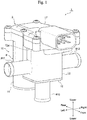
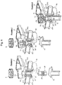
- Fig. 1 is a perspective view of the overall configuration of an embodiment of a flow channel switching valve in accordance with the present invention.
- Fig. 2 is a partial longitudinal cross-sectional perspective view of the flow channel switching valve illustrated in Fig. 1 .
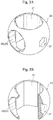
- Figs. 3A and 3B illustrate the valve element in Fig. 2 .
- Fig. 3A is a perspective view of the valve element
- Fig. 3B is a partially cutaway perspective view of the valve element (i.e., a portion thereof at a central angle of 90° as seen in plan view is cut out).
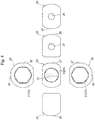
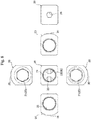
- Fig. 4 is a view of six sides of the valve element in Figs. 3A and 3B .
- the flow channel switching valve 1 of the embodiment illustrated in the drawings is used as a rotary three-way valve that switches a flow channel for a fluid flowing through the inside of an engine room of an automobile to multiple directions, for example, and basically includes a valve body 10 with a valve chamber 11, a ball-shaped valve element (also referred to as a ball valve element) 20 rotatably arranged within the valve chamber 11, a rotary drive portion 5 that includes a motor 8, a drive gear 9, and the like and is arranged in a region of from the rear portion to the upper portion of the valve body 10 so as to rotate the valve element 20 about the rotation axis (i.e., center line) O.
- the valve body 10 and the rotary drive portion 5 are integrally formed.
- rotation axis i.e., axis extending in the vertical direction
- O of the valve element 20 housed within the valve chamber 11 is coaxial with the center lines of an inlet port p10 and a valve shaft 28 (described below).
- the valve body 10 includes a base member 12 with a rectangular tube shape, which is made of synthetic resin or metal, for example, and has a ceiling portion 12a, and a holder member 15.
- the base member 12 has formed therein a cylindrical valve chamber 11 lying on its side.
- the base member 12 is provided on its left and right sides with an outlet port (i.e., inlet/outlet port) p11 and an outlet port (i.e., inlet/outlet port) p12, respectively, that open to the valve chamber 11 and face the lateral sides.
- Ports #11 and #12 each made of a pipe joint are integrally coupled to the outer periphery of the base member 12 so as to communicate with the outlet ports p11 and p12, respectively.
- the ceiling portion 12a of the base member 12 has a fit-insertion hole 13 through which the valve shaft 28 (or an intermediate trunk portion 28b thereof) to be coupled to the valve element 20 is adapted to be inserted, and also has protrusions 14a and 14b for positioning annular seat members 31 and 32 (described below) that are disposed in a (downwardly) protruding manner about halfway around the left and right sides of the fit-insertion hole 13 (more specifically, at positions slightly closer the left and right sides around the fit-insertion hole 13 than to the portion abutted and engaged by a step portion 28s between a lower engagement portion 28a and an intermediate trunk portion 28b of the valve shaft 28 (described below)) (see also Fig. 5 ).
- the holder member 15 with a port #10 which is made of a pipe joint and provided with a vertical inlet port (i.e., inlet/outlet port) p10 opening to the valve chamber 11, is securely fitted into an opening at the lower end of the base member 12 through ultrasonic welding, screwing, press fitting, or swaging, for example (through ultrasonic welding in the example illustrated in the drawing).
- valve body 10 is provided with the inlet port p10 opening to the bottom of the valve chamber 11, and the outlet ports (i.e., lateral inlet/outlet ports) p11 and p12 disposed at an angular interval of 180° therebetween (that is, at opposite sides across the rotation axis O of the valve element 20) and opening to the lateral sides of the valve chamber 11.
- outlet ports i.e., lateral inlet/outlet ports
- the rear portion of the base member 12 of the valve body 10 has integrally formed therewith a motor case portion 16, which houses the motor 8 forming the rotary drive portion 5 for rotating the valve element 20 (or the valve shaft 28 coupled thereto), while the upper portion of the base member 12 (i.e., upper face side of the ceiling portion 12a) has integrally formed therewith a gear case portion 17 that houses the drive gear 9 coupled to the motor 8 and the like for transmitting torque of the motor 8 to the valve shaft 28.
- the valve element 20 is produced from synthetic resin or metal, for example, and includes a flow channel (i.e., internal flow channel) 25 therein to allow the inlet port p10 and one of the two outlet ports p11 and p12 provided in the valve body 10 to selectively communicate with each other, that is, selectively switch the communication state between the inlet port p10 and one of the two outlet ports p11 and p12.
- a flow channel i.e., internal flow channel
- the internal flow channel 25 includes a through-hole penetrating through the valve element 20 from its bottom to the lateral side.
- the bottom opening of the through-hole always communicates with the inlet port p10, and the lateral opening of the through-hole is allowed to selectively communicate with one of the two outlet ports p11 and p12.
- the valve element 20 has formed therein a vertical through-hole 21 with an approximately hexagonal cross-section that penetrates through the valve element 20 in the vertical direction (i.e., direction of the rotation axis O of the valve element 20; openings at the upper and lower ends of the vertical through-hole 21 are approximately hexagonal in shape), and also has formed therein a horizontal hole 22 with an approximately hexagonal cross-section that merges with the center of the vertical through-hole 21 from the outer periphery (i.e., lateral side) of the valve element 20 (i.e., in the direction orthogonal to the rotation axis O of the valve element 20).
- the vertical through-hole 21 (or the bottom opening thereof) always communicates with the inlet port p10, while the horizontal hole 22 (or the lateral opening thereof) is allowed to selectively communicate with one of the two outlet ports p11 and p12.
- the lower half of the vertical through-hole 21 and the horizontal hole 22 form the internal flow channel 25 with an inverted L shape as seen in side view (in the valve element 20).
- the outer periphery (i.e., outer peripheral seal face) of the valve element 20 specifically, the rear side of the lateral opening of the horizontal hole 22 and the lateral side of the lateral opening of the horizontal hole 22 on the outer periphery of the valve element 20 are provided with hexagon sockets (recess holes each having a hexagonal shape as seen in side view) 26 and 27, respectively, as rotation engagement portions for arranging the valve element 20 within the valve chamber 11 by rotating it during assembly (which will be described in detail later).
- valve element 20 (or the upper portion of the vertical through-hole 21 thereof) has coupled thereto the valve shaft 28 (or the lower portion of the lower engagement portion 28a thereof) with a stepped portion for transmitting torque of the motor 8 to the valve element 20.
- the valve shaft 28 includes, sequentially arranged from its bottom, the lower engagement portion 28a having a shape complementary (i.e., approximately hexagonal cross-section) to that of the vertical through-hole 21 of the valve element 20 or a slightly smaller shape than that of the vertical through-hole 21, the intermediate trunk portion 28b having a circular cross-section and a slightly smaller shape than that of the lower engagement portion 28a, an upper coupling portion 28c having an approximately hexagonal cross-section and substantially the same outside diameter as that of the intermediate trunk portion 28b, and a D-cut projection 28d to be used for circumferential positioning that is provided in a protruding manner on the upper coupling portion 28c.
- the lower engagement portion 28a having a shape complementary (i.e., approximately hexagonal cross-section) to that of the vertical through-hole 21 of the valve element 20 or a slightly smaller shape than that of the vertical through-hole 21, the intermediate trunk portion 28b having a circular cross-section and a slightly smaller shape than that of the lower engagement portion 28a, an upper coupling portion 28
- the lower engagement portion 28a (or the lower portion thereof) is fitted and inserted into the top opening of the vertical through-hole 21, and the intermediate trunk portion 28b is inserted through (the inside of) the fit-insertion hole 13 of the valve body 10 so that the upper coupling portion 28c protrudes upward (i.e., toward the upper face side of the ceiling portion 12a) from the fit-insertion hole 13.
- O-rings 29 as seal members are disposed in two stages around the intermediate trunk portion 28b (or in annular grooves formed on the outer periphery thereof) rotatably inserted through the fit-insertion hole 13.
- valve element 20 is caused to engage the valve shaft 28 in a mutually non-rotatable manner about the rotation axis O, and thus, the valve shaft 28 and the valve element 20 rotate integrally.
- the step portion 28s formed between the lower engagement portion 28a and the intermediate trunk portion 28b of the valve shaft 28 is caused to abut and engage the inner periphery of the fit-insertion hole 13 of the ceiling portion 12a of the valve body 10 (or the base member 12 thereof).
- the drive gear 9 of the rotary drive portion 5 is externally fitted around and fixed to the upper coupling portion 28c of the valve shaft 28 protruding from the fit-insertion hole 13 through press fitting or swaging, for example.
- the valve shaft 28 is rotatably supported with respect to the valve body 10 (without moving in the vertical direction) such that the ceiling portion 12a of the valve body 10 is sandwiched between the step portion 28s (or the upper face thereof) and the drive gear 9 (or the lower face thereof).
- valve shaft 28 can be inserted through the vertical through-hole 21 in the vertical direction (i.e., direction of the rotation axis O) (which will be described in detail later).
- annular seat members 31 and 32 made of Teflon (registered trademark), for example, and having openings corresponding to the outlet ports p11 and p12, respectively, are arranged around the outlet ports p11 and p12 on the inner wall faces of the valve body 10 (i.e., left and right end faces of the valve chamber 11). That is, the pair of seat members 31 and 32 are arranged on opposite sides across the rotation axis O of the valve element 20, corresponding to the pair of left and right outlet ports p11 and p12, respectively, within the valve chamber 11 of the valve body 10, and the valve element 20 is rotatably and slidably arranged between (i.e., on the inner side of) the pair of seat members 31 and 32.
- Teflon registered trademark
- each of the seat members 31 and 32 around the opening on the inner periphery is formed as a curved face (i.e., a part of a recessed spherical face), and serves as an inner peripheral seal face that is positioned opposite the outer peripheral seal face (i.e., curved face) of the valve element 20 when a flow channel is formed.
- the height H in the vertical direction (i.e., direction of the rotation axis O) of the valve element 20 arranged between the pair of seat members 31 and 32 is set less than or equal to the distance L between the seat members 31 and 32 or slightly less than that (which will be described in detail later).
- O-rings (i.e., elastic members) 33 and 34 which are seal members made of elastic materials, such as rubber, are disposed (in a compressed state) between the seat members 31 and 32 and the valve body 10 (or around the outlet ports p11 and p12, respectively; specifically, in annular grooves formed on the left face of the seat member 31 (i.e., face on the side of the outlet port p11) and on the right face of the seat member 32 (i.e., face on the side of the outlet port p12)). Due to the elastic force (i.e., repulsive force) of the O-rings 33 and 34, the seat members 31 and 32 (or the inner peripheral seal faces thereof) are tightly pressed against the valve element 20 (or the outer peripheral seal face thereof). Accordingly, the gap between the valve element 20 and each of the outlet ports p11 and p12 is sealed hermetically.
- elastic force i.e., repulsive force
- the flow channel switching valve i.e., three-way valve 1 with such a configuration
- the valve element 20 when the valve element 20 is rotated within the valve chamber 11 by the rotary drive portion 5 including the motor 8, the drive gear 9, and the like, the communication state between the inlet port p10 and one of the two outlet ports p11 and p12 provided in the valve body 10 is selectively switched via the internal flow channel 25 provided in the valve element 20.
- the mode is selectively switched between a mode (i.e., first communication state) in which the inlet port p10 provided at the bottom of the valve body 10 and the outlet port p11 provided on the left side communicate with each other (via the internal flow channel 25 including the lower half of the vertical through-hole 21 and the horizontal hole 22) and a mode (i.e., second communication state) in which the inlet port p10 provided at the bottom of the valve body 10 and the outlet port p12 provided on the right side communicate with each other (via the internal flow channel 25 including the lower half of the vertical through-hole 21 and the horizontal hole 22).
- a mode i.e., first communication state
- second communication state i.e., second communication state
- the opening of the seat member 32 corresponding to the outlet port p12 on the right side is blocked by the valve element 20 (or the outer peripheral seal face thereof; herein, a portion where the hexagon socket 26 is formed), and the flow channel connecting to the outlet port p12 is blocked so that a fluid that has flowed upward via the inlet port p10 passes through the internal flow channel 25 of the valve element 20 and flows out of only the outlet port p11 on the left side.
- the opening of the seat member 31 corresponding to the outlet port p11 on the left side is blocked by the valve element 20 (or the outer peripheral seal face thereof; herein, a portion where the hexagon socket 26 is formed), and the flow channel connecting to the outlet port p11 is blocked so that a fluid that has flowed upward via the inlet port p10 passes through the internal flow channel 25 of the valve element 20, and flows out of only the outlet port p12 on the right side.
- the flow channel switching valve (i.e., three-way valve) 1 with the aforementioned configuration is assembled through the following procedures, for example.
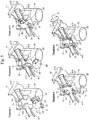
- Figs. 5 and 6 each illustrate procedures for assembling the flow channel switching valve illustrated in Fig. 1 .
- Fig. 5 illustrates procedures for disposing the valve element within the valve chamber
- Fig. 6 illustrates procedures for fixing the valve shaft to the valve body such that the valve shaft is supported on the valve body.
- the O-rings 33 and 34 are first arranged on the seat members 31 and 32 (or in the annular recess grooves thereof), respectively (Procedure 1), and before the holder member 15 is attached to the base member 12 (or the opening at the lower end thereof) forming the valve body 10, the seat members 31 and 32 with the O-rings 33 and 34, respectively, are arranged inside the base member 12 via the opening at the lower end thereof (that is, within the valve chamber 11; around the left and right outlet ports p11 and p12 thereof, respectively) (Procedure 2).
- the seat members 31 and 32 are positioned within the valve chamber 11 using the protrusions 14a and 14b provided on the ceiling portion 12a of the base member 12, respectively, and the distance between the seat members 31 and 32 is set greater than or equal to the height of the valve element 20 in the vertical direction (i.e., direction of the rotation axis O) or slightly greater than that.
- the valve element 20 which has formed therein the internal flow channel 25 including the vertical through-hole 21 and the horizontal hole 22, is arranged within the base member 12 (specifically, between the seat members 31 and 32 arranged around the outlet ports p11 and p12, respectively, within the valve chamber 11) via the bottom opening of the base member 12 (i.e., opening with an outer shape (or outside diameter) greater than or equal to that of the valve element 20) in a posture in which the valve element 20 is laid on its side (i.e., a posture in which the direction of the rotation axis of the valve element 20 is made horizontal or the rotation axis of the valve element 20 faces the lateral sides, and the upper and lower end faces of the valve element 20 face the left and right seat members 31 and 32) and the hexagon socket 26 faces downward (Procedure 3).
- a rotating jig G such as a hexagonal wrench, having a head with a hexagonal cross-section at its tip end is inserted through the bottom opening of the base member 12, for example, and the head is fitted into (or is caused to engage) the hexagon socket (i.e., rotation engagement portion) 26 of the valve element 20 so as to rotate the rotating jig G.
- the valve element 20 is rotated by about 90° between the seat members 31 and 32 within the valve chamber 11 (i.e., rotated counterclockwise by about 90° about the axis extending in the vertical direction as seen from the lower side) (Procedure 4).
- the outer periphery (i.e., outer peripheral seal face) of the valve element 20 slides on the left and right seat members 31 and 32
- the O-rings 33 and 34 arranged on the outer sides of the seat member 31 and 32, respectively, are slightly compressed so that the outer periphery (i.e., outer peripheral seal face) of the valve element 20 is in pressure-contact with the seat members 31 and 32 (or the inner peripheral seal faces thereof).
- a rotating jig G which is similar to the aforementioned one, is inserted through the port #12 on the right side of the base member 12, and its head is fitted into (or is caused to engage) the hexagon socket (i.e., rotation engagement portion) 27 of the valve element 20 so as to rotate the rotating jig G. Accordingly, the valve element 20 is rotated by about 90° between the seat members 31 and 32 within the valve chamber 11 (i.e., rotated counterclockwise by about 90° about the axis extending in the horizontal direction as seen from the right side) (Procedure 5).
- valve element 20 is rotated about two axes that are orthogonal to the rotation axis O between the seat members 31 and 32 within the valve chamber 11 so that the valve element 20 is arranged within the valve chamber 11 in a posture in which the valve element 20 is used (i.e., posture in which the direction of the rotation axis O of the valve element 20 lies along the vertical direction and the vertical through-hole 21 faces the upper and lower sides).
- the O-rings 29 are arranged around the intermediate trunk portion 28b of the valve shaft 28 (Procedure 6). Then, in a state in which the rotation position (i.e., angular position around the rotation axis O) between the lower engagement portion 28a of the valve shaft 28 and the vertical through-hole 21 of the valve element 20 is positioned, the valve shaft 28 is inserted into the vertical through-hole 21 of the valve element 20 via the bottom opening of the base member 12 until the step portion 28s between the lower engagement portion 28a and the intermediate trunk portion 28b of the valve shaft 28 abuts the ceiling portion 12a of the base member 12 of the valve body 10 (or the inner periphery of the fit-insertion hole 13 thereof).
- the rotation position i.e., angular position around the rotation axis O
- the lower engagement portion 28a (or the lower portion thereof) of the valve shaft 28 is fitted and inserted into the top opening of the vertical through-hole 21 (in a state in which the lower engagement portion 28a is caused to engage the top opening of the vertical through-hole 21 in a mutually non-rotatable manner about the rotation axis O), and the intermediate trunk portion 28b is inserted through the fit-insertion hole 13 of the valve body 10 so that the upper coupling portion 28c protrudes upward from the fit-insertion hole 13 (Procedure 7).
- the holder member 15 is attached to the bottom opening of the base member 12 through ultrasonic welding or screwing, for example, and the drive gear 9 of the rotary drive portion 5 is attached to the upper coupling portion 28c of the valve shaft 28 protruding from the fit-insertion hole 13 through press fitting or swaging, for example, so that the valve shaft 28 is fixed to the valve body 10 such that the valve shaft 28 is rotatably supported on the valve body 10 while slippage of the valve shaft 28 is prevented (Procedure 8). Further, the motor 8 and the like forming the rotary drive portion 5 are attached to the valve body 10 so as to assemble the flow channel switching valve 1.
- the distance between the seat members 31 and 32 arranged within the valve chamber 11 is set greater than or equal to the height of the valve element 20 in the vertical direction (i.e., direction of the rotation axis O) or slightly greater than that so as to allow the valve element 20 to be smoothly inserted into the valve chamber 11.
- the left and right O-rings 33 and 34 may be compressed via the seat members 31 and 32, respectively, when the valve element 20 is inserted (i.e., compressed with a compressive force that is greater than the compressive force acting on the O-rings 33 and 34 during the normal use) so that the distance between the seat members 31 and 32 may be increased through push-out and the valve element 20 may thus be arranged between the seat members 31 and 32.
- the valve shaft 28 which is adapted to be coupled to the valve element 20 so as to transmit torque of the rotary drive portion 5 to the valve element 20, is inserted through the vertical through-hole 21 penetrating through the valve element 20 in the direction of the rotation axis O (i.e., vertical direction), and through the fit-insertion hole 13 provided in the valve body 10, and the drive gear 9 forming the rotary drive portion 5 is fixed to the upper coupling portion 28c of the valve shaft 28 protruding from the fit-insertion hole 13 so that the valve shaft 28 is rotatably supported with respect to the valve body 10 by the drive gear 9. Therefore, the number of components and the weight of the valve can be suppressed in comparison with a conventional flow channel switching valve that uses a pressing plate and fixation members, such as screws, for example.
- the configuration, shape, and the like of the internal flow channel 25 formed inside the valve element 20 can be changed as appropriate in accordance with the intended use of the flow channel switching valve 1, for example.
- a horizontal through-hole 23 with an approximately hexagonal cross-section i.e., having hexagonal lateral openings
- the aforementioned hexagon socket (i.e., rotation engagement portion) 27 is omitted, but the horizontal through-hole 23 (or an opening at an end thereof) may be used as a rotation engagement portion like the aforementioned hexagon socket 27.
- the bottom opening of the vertical through-hole 21 is in the shape of a circle that is slightly larger than the top opening of the hexagon as seen in plan view.
- the mode is selectively switched among three modes including a mode (i.e., first communication state) in which the inlet port p10 provided at the bottom of the valve body 10 and only the outlet port p11 provided on the left side of the valve body 10 communicate with each other (via the internal flow channel 25 including the lower half of the vertical through-hole 21 and the horizontal hole 22), a mode (i.e., second communication state) in which the inlet port p10 provided at the bottom of the valve body 10 and both the outlet ports p11 and p12 provided on the left and right sides of the valve body 10 communicate with the each other (via the internal flow channel 25 including the lower half of the vertical through-hole 21 and the horizontal through-hole 23),
- a mode i.e., first communication state
- the horizontal through-hole 23 such as the one illustrated in Figs. 7A, 7B , and 8 may be provided instead of the horizontal hole 22 without the need for specific illustration.
- an appropriate shape may be selected for the cross-sectional shape of each of the vertical through-hole 21, the horizontal hole 22, the horizontal through-hole 23, and the hexagon sockets 26 and 27, which serves as the rotation engagement portions, formed in the valve element 20.
- the cross-sectional shape of each of the vertical through-hole 21 and the horizontal through-hole 23 may be a polygonal shape other than a hexagon or an elliptical shape, for example, while the lateral opening of the horizontal hole 22 may be a polygonal shape other than a hexagon, an elliptical shape, or a circular shape, for example.
- each of the hexagon sockets 26 and 27 may be a hole with a polygonal shape other than a hexagon or an elliptical shape, for example, as long as the valve element 20 can be rotated within the valve chamber 11 during assembly.
- inlet/outlet ports i.e., inlet ports and outlet ports
- the number, arrangement, and configuration of the inlet/outlet ports (i.e., inlet ports and outlet ports) formed in the valve body 10 may be changed as appropriate in accordance with a portion to which the flow channel switching valve 1 is applied.
- the aforementioned embodiment illustrates an example of a three-way valve in which the inlet port p10 opens to the bottom of the valve chamber 11, and the two outlet ports p11 and p12 are disposed at an angular interval of 180° therebetween and open to the lateral sides of the valve chamber 11, as the flow channel switching valve 1, it is also possible to use, for example, a two-way valve in which the inlet port on the bottom side is omitted and one of the outlet ports on the lateral sides is used as the inlet port instead, or a four or more-way valve in which the number, arrangement, and configuration, for example, of the inlet ports and the outlet ports that open to the valve chamber are changed.
- the flow channel switching valve 1 of the aforementioned embodiment is used to switch a flow channel in an engine room (e.g., engine cooling circuit or electronic device cooling circuit) of a vehicle, it is needless to say that the flow channel switching valve 1 may also be used to switch a flow channel in a hot-water supply apparatus, for example.
- an engine room e.g., engine cooling circuit or electronic device cooling circuit
- the flow channel switching valve 1 may also be used to switch a flow channel in a hot-water supply apparatus, for example.
Landscapes
- Engineering & Computer Science (AREA)
- General Engineering & Computer Science (AREA)
- Mechanical Engineering (AREA)
- Multiple-Way Valves (AREA)
- Taps Or Cocks (AREA)
Applications Claiming Priority (2)
| Application Number | Priority Date | Filing Date | Title |
|---|---|---|---|
| JP2017006030A JP6745529B2 (ja) | 2017-01-17 | 2017-01-17 | 流路切換弁及びその組立方法 |
| PCT/JP2017/040421 WO2018135103A1 (ja) | 2017-01-17 | 2017-11-09 | 流路切換弁及びその組立方法 |
Publications (3)
| Publication Number | Publication Date |
|---|---|
| EP3572696A1 EP3572696A1 (en) | 2019-11-27 |
| EP3572696A4 EP3572696A4 (en) | 2020-12-16 |
| EP3572696B1 true EP3572696B1 (en) | 2021-12-22 |
Family
ID=62908677
Family Applications (1)
| Application Number | Title | Priority Date | Filing Date |
|---|---|---|---|
| EP17893100.2A Active EP3572696B1 (en) | 2017-01-17 | 2017-11-09 | Channel switching valve and method for assembling same |
Country Status (6)
| Country | Link |
|---|---|
| US (1) | US11073216B2 (ko) |
| EP (1) | EP3572696B1 (ko) |
| JP (1) | JP6745529B2 (ko) |
| KR (2) | KR102362453B1 (ko) |
| CN (1) | CN110199144B (ko) |
| WO (1) | WO2018135103A1 (ko) |
Families Citing this family (11)
| Publication number | Priority date | Publication date | Assignee | Title |
|---|---|---|---|---|
| US11054044B2 (en) * | 2018-02-14 | 2021-07-06 | Fisher Controls International Llc | Ball valve having a ball valve element with rotation control |
| JP6951706B2 (ja) * | 2018-07-17 | 2021-10-20 | 株式会社不二工機 | 流路切換弁およびその組立方法 |
| JP6999177B2 (ja) * | 2018-11-08 | 2022-01-18 | 株式会社不二工機 | 弁装置およびその組立方法 |
| JP7228694B2 (ja) * | 2018-12-24 | 2023-02-24 | ジャージャン サンフア オートモーティヴ コンポーネンツ カンパニー リミテッド | ボールバルブ |
| JP7058418B2 (ja) * | 2019-02-05 | 2022-04-22 | 株式会社不二工機 | 流路切換弁 |
| JP6737380B1 (ja) | 2019-06-11 | 2020-08-05 | 株式会社デンソー | バルブ装置 |
| CN210770428U (zh) * | 2019-06-24 | 2020-06-16 | 盾安环境技术有限公司 | 三通水阀 |
| GB2586482B (en) * | 2019-08-20 | 2022-08-17 | Singh Bath Charanjit | Modified ball valve |
| JP7419752B2 (ja) * | 2019-11-07 | 2024-01-23 | 株式会社デンソー | バルブ装置 |
| CN114811110A (zh) * | 2021-01-29 | 2022-07-29 | 浙江三花汽车零部件有限公司 | 电动阀 |
| JP2023038775A (ja) | 2021-09-07 | 2023-03-17 | 株式会社不二工機 | 弁装置及び弁本体部 |
Family Cites Families (21)
| Publication number | Priority date | Publication date | Assignee | Title |
|---|---|---|---|---|
| US3014690A (en) * | 1960-09-26 | 1961-12-26 | Grinnell Corp | Ball valve |
| JPS5147630A (ja) | 1974-10-21 | 1976-04-23 | Nippon Air Brake Co | Boorukotsuku |
| JPS5223730A (en) * | 1975-08-15 | 1977-02-22 | Taisei Kk | Three ways angle cock |
| US4319734A (en) * | 1981-03-09 | 1982-03-16 | International Telephone And Telegraph Corporation | Valve |
| JPS5913170A (ja) * | 1982-07-14 | 1984-01-23 | Tlv Co Ltd | 多方向ボ−ル弁 |
| JPS5916170A (ja) | 1982-07-19 | 1984-01-27 | Matsushita Electric Ind Co Ltd | 再生装置 |
| US5313976A (en) * | 1993-07-26 | 1994-05-24 | Keystone International Holdings, Corp. | Top entry ball valve and method of assembly |
| DE29505320U1 (de) * | 1995-03-29 | 1995-05-24 | Postberg Anne Karin Maria | Absperrventil für eine Meßvorrichtung |
| US5868378A (en) * | 1997-01-28 | 1999-02-09 | Fisher Controls International, Inc. | Throttling control in a fluid control valve |
| DE60330398D1 (de) * | 2002-01-18 | 2010-01-14 | Swagelok Co | Kugelhahn mit einstückiger Dichtungspackung |
| JP2006090408A (ja) | 2004-09-22 | 2006-04-06 | Nichiden Kogyo Kk | 弁装置 |
| CN201306471Y (zh) * | 2008-12-08 | 2009-09-09 | 北京长空机械有限责任公司 | 一种换向阀 |
| JP2010223418A (ja) | 2009-02-26 | 2010-10-07 | Fuji Koki Corp | ボールバルブ |
| CN101586674B (zh) * | 2009-06-23 | 2012-05-30 | 广东联塑科技实业有限公司 | 一种下装式塑料球阀 |
| JP5615117B2 (ja) * | 2010-09-28 | 2014-10-29 | 株式会社ケーヒン | 流路開閉弁 |
| JP5822586B2 (ja) | 2011-07-28 | 2015-11-24 | 株式会社不二工機 | ボール弁 |
| CN203797046U (zh) | 2014-03-04 | 2014-08-27 | 四川飞球(集团)有限责任公司 | 一种侧装式三通球阀及其装配工具 |
| CN203868411U (zh) | 2014-05-29 | 2014-10-08 | 余姚凯登机电数控有限公司 | 两位三通阀 |
| CN204004574U (zh) * | 2014-08-05 | 2014-12-10 | 江苏科维仪表控制工程有限公司 | 耳轴球阀 |
| JP2016138626A (ja) * | 2015-01-29 | 2016-08-04 | 三菱電機株式会社 | 切替弁 |
| US10295076B2 (en) * | 2016-11-02 | 2019-05-21 | Schaeffler Technologies AG & Co. KG | Modular electro-mechanical rotary valve with activated seal interface |
-
2017
- 2017-01-17 JP JP2017006030A patent/JP6745529B2/ja active Active
- 2017-01-17 US US16/477,769 patent/US11073216B2/en active Active
- 2017-11-09 CN CN201780083704.1A patent/CN110199144B/zh active Active
- 2017-11-09 EP EP17893100.2A patent/EP3572696B1/en active Active
- 2017-11-09 WO PCT/JP2017/040421 patent/WO2018135103A1/ja unknown
- 2017-11-09 KR KR1020197017400A patent/KR102362453B1/ko active IP Right Grant
- 2017-11-09 KR KR1020227004316A patent/KR102404396B1/ko active IP Right Grant
Also Published As
| Publication number | Publication date |
|---|---|
| JP2018115691A (ja) | 2018-07-26 |
| KR102362453B1 (ko) | 2022-02-14 |
| EP3572696A1 (en) | 2019-11-27 |
| CN110199144B (zh) | 2021-03-19 |
| EP3572696A4 (en) | 2020-12-16 |
| KR20220025166A (ko) | 2022-03-03 |
| CN110199144A (zh) | 2019-09-03 |
| US20200141502A1 (en) | 2020-05-07 |
| KR102404396B1 (ko) | 2022-06-02 |
| WO2018135103A1 (ja) | 2018-07-26 |
| KR20190107660A (ko) | 2019-09-20 |
| JP6745529B2 (ja) | 2020-08-26 |
| US11073216B2 (en) | 2021-07-27 |
Similar Documents
| Publication | Publication Date | Title |
|---|---|---|
| EP3572696B1 (en) | Channel switching valve and method for assembling same | |
| JP6511427B2 (ja) | 流路切換弁 | |
| WO2018135102A1 (ja) | 流路切換弁及びその組立方法 | |
| JP5800836B2 (ja) | マイクロ流体弁取り付け装置、マイクロ流体弁アセンブリ、及び、マイクロ流体弁システム | |
| CN108397554B (zh) | 电动阀 | |
| EP3379117B1 (en) | Valve device and air conditioning device | |
| JP7403182B2 (ja) | 流路切換弁 | |
| US6837442B2 (en) | Expansion valve | |
| JP7026962B2 (ja) | 流路切換弁及びその組立方法 | |
| EP1411282B1 (en) | Ball valve with a rotable seal | |
| CN111750135A (zh) | 分配阀、阀芯以及制冷系统 | |
| JPH0718492B2 (ja) | 単一ハンドル型混合弁 | |
| CN117128351A (zh) | 阀致动器 | |
| CN117231792A (zh) | 阀致动器 | |
| CN116472385A (zh) | 卫生出口单元和用于安装和/或拆卸其的方法 | |
| CN111434961A (zh) | 阀 | |
| CN112128407A (zh) | 流体管理组件 | |
| JP2004162822A (ja) | 多方向切換弁 | |
| CN116697100A (zh) | 控制阀 | |
| CN114909494A (zh) | 温控阀 |
Legal Events
| Date | Code | Title | Description |
|---|---|---|---|
| STAA | Information on the status of an ep patent application or granted ep patent |
Free format text: STATUS: THE INTERNATIONAL PUBLICATION HAS BEEN MADE |
|
| PUAI | Public reference made under article 153(3) epc to a published international application that has entered the european phase |
Free format text: ORIGINAL CODE: 0009012 |
|
| STAA | Information on the status of an ep patent application or granted ep patent |
Free format text: STATUS: REQUEST FOR EXAMINATION WAS MADE |
|
| 17P | Request for examination filed |
Effective date: 20190819 |
|
| AK | Designated contracting states |
Kind code of ref document: A1 Designated state(s): AL AT BE BG CH CY CZ DE DK EE ES FI FR GB GR HR HU IE IS IT LI LT LU LV MC MK MT NL NO PL PT RO RS SE SI SK SM TR |
|
| AX | Request for extension of the european patent |
Extension state: BA ME |
|
| DAV | Request for validation of the european patent (deleted) | ||
| DAX | Request for extension of the european patent (deleted) | ||
| A4 | Supplementary search report drawn up and despatched |
Effective date: 20201116 |
|
| RIC1 | Information provided on ipc code assigned before grant |
Ipc: F16K 11/087 20060101AFI20201110BHEP Ipc: F16K 31/53 20060101ALI20201110BHEP Ipc: F16K 5/06 20060101ALI20201110BHEP |
|
| GRAP | Despatch of communication of intention to grant a patent |
Free format text: ORIGINAL CODE: EPIDOSNIGR1 |
|
| STAA | Information on the status of an ep patent application or granted ep patent |
Free format text: STATUS: GRANT OF PATENT IS INTENDED |
|
| INTG | Intention to grant announced |
Effective date: 20210701 |
|
| RIN1 | Information on inventor provided before grant (corrected) |
Inventor name: KONDO, DAISUKE Inventor name: MOCHIZUKI, KENICHI Inventor name: YAMASHITA, MASASHI Inventor name: HARA, SEIICHI Inventor name: MATSUMOTO, TAKAYUKI |
|
| GRAS | Grant fee paid |
Free format text: ORIGINAL CODE: EPIDOSNIGR3 |
|
| GRAA | (expected) grant |
Free format text: ORIGINAL CODE: 0009210 |
|
| STAA | Information on the status of an ep patent application or granted ep patent |
Free format text: STATUS: THE PATENT HAS BEEN GRANTED |
|
| AK | Designated contracting states |
Kind code of ref document: B1 Designated state(s): AL AT BE BG CH CY CZ DE DK EE ES FI FR GB GR HR HU IE IS IT LI LT LU LV MC MK MT NL NO PL PT RO RS SE SI SK SM TR |
|
| REG | Reference to a national code |
Ref country code: GB Ref legal event code: FG4D |
|
| REG | Reference to a national code |
Ref country code: CH Ref legal event code: EP |
|
| REG | Reference to a national code |
Ref country code: DE Ref legal event code: R096 Ref document number: 602017051405 Country of ref document: DE |
|
| REG | Reference to a national code |
Ref country code: AT Ref legal event code: REF Ref document number: 1457283 Country of ref document: AT Kind code of ref document: T Effective date: 20220115 |
|
| REG | Reference to a national code |
Ref country code: IE Ref legal event code: FG4D |
|
| REG | Reference to a national code |
Ref country code: LT Ref legal event code: MG9D |
|
| PG25 | Lapsed in a contracting state [announced via postgrant information from national office to epo] |
Ref country code: RS Free format text: LAPSE BECAUSE OF FAILURE TO SUBMIT A TRANSLATION OF THE DESCRIPTION OR TO PAY THE FEE WITHIN THE PRESCRIBED TIME-LIMIT Effective date: 20211222 Ref country code: LT Free format text: LAPSE BECAUSE OF FAILURE TO SUBMIT A TRANSLATION OF THE DESCRIPTION OR TO PAY THE FEE WITHIN THE PRESCRIBED TIME-LIMIT Effective date: 20211222 Ref country code: FI Free format text: LAPSE BECAUSE OF FAILURE TO SUBMIT A TRANSLATION OF THE DESCRIPTION OR TO PAY THE FEE WITHIN THE PRESCRIBED TIME-LIMIT Effective date: 20211222 Ref country code: BG Free format text: LAPSE BECAUSE OF FAILURE TO SUBMIT A TRANSLATION OF THE DESCRIPTION OR TO PAY THE FEE WITHIN THE PRESCRIBED TIME-LIMIT Effective date: 20220322 |
|
| REG | Reference to a national code |
Ref country code: NL Ref legal event code: MP Effective date: 20211222 |
|
| REG | Reference to a national code |
Ref country code: AT Ref legal event code: MK05 Ref document number: 1457283 Country of ref document: AT Kind code of ref document: T Effective date: 20211222 |
|
| PG25 | Lapsed in a contracting state [announced via postgrant information from national office to epo] |
Ref country code: SE Free format text: LAPSE BECAUSE OF FAILURE TO SUBMIT A TRANSLATION OF THE DESCRIPTION OR TO PAY THE FEE WITHIN THE PRESCRIBED TIME-LIMIT Effective date: 20211222 Ref country code: NO Free format text: LAPSE BECAUSE OF FAILURE TO SUBMIT A TRANSLATION OF THE DESCRIPTION OR TO PAY THE FEE WITHIN THE PRESCRIBED TIME-LIMIT Effective date: 20220322 Ref country code: LV Free format text: LAPSE BECAUSE OF FAILURE TO SUBMIT A TRANSLATION OF THE DESCRIPTION OR TO PAY THE FEE WITHIN THE PRESCRIBED TIME-LIMIT Effective date: 20211222 Ref country code: HR Free format text: LAPSE BECAUSE OF FAILURE TO SUBMIT A TRANSLATION OF THE DESCRIPTION OR TO PAY THE FEE WITHIN THE PRESCRIBED TIME-LIMIT Effective date: 20211222 Ref country code: GR Free format text: LAPSE BECAUSE OF FAILURE TO SUBMIT A TRANSLATION OF THE DESCRIPTION OR TO PAY THE FEE WITHIN THE PRESCRIBED TIME-LIMIT Effective date: 20220323 |
|
| PG25 | Lapsed in a contracting state [announced via postgrant information from national office to epo] |
Ref country code: NL Free format text: LAPSE BECAUSE OF FAILURE TO SUBMIT A TRANSLATION OF THE DESCRIPTION OR TO PAY THE FEE WITHIN THE PRESCRIBED TIME-LIMIT Effective date: 20211222 |
|
| PG25 | Lapsed in a contracting state [announced via postgrant information from national office to epo] |
Ref country code: SM Free format text: LAPSE BECAUSE OF FAILURE TO SUBMIT A TRANSLATION OF THE DESCRIPTION OR TO PAY THE FEE WITHIN THE PRESCRIBED TIME-LIMIT Effective date: 20211222 Ref country code: SK Free format text: LAPSE BECAUSE OF FAILURE TO SUBMIT A TRANSLATION OF THE DESCRIPTION OR TO PAY THE FEE WITHIN THE PRESCRIBED TIME-LIMIT Effective date: 20211222 Ref country code: RO Free format text: LAPSE BECAUSE OF FAILURE TO SUBMIT A TRANSLATION OF THE DESCRIPTION OR TO PAY THE FEE WITHIN THE PRESCRIBED TIME-LIMIT Effective date: 20211222 Ref country code: PT Free format text: LAPSE BECAUSE OF FAILURE TO SUBMIT A TRANSLATION OF THE DESCRIPTION OR TO PAY THE FEE WITHIN THE PRESCRIBED TIME-LIMIT Effective date: 20220422 Ref country code: ES Free format text: LAPSE BECAUSE OF FAILURE TO SUBMIT A TRANSLATION OF THE DESCRIPTION OR TO PAY THE FEE WITHIN THE PRESCRIBED TIME-LIMIT Effective date: 20211222 Ref country code: EE Free format text: LAPSE BECAUSE OF FAILURE TO SUBMIT A TRANSLATION OF THE DESCRIPTION OR TO PAY THE FEE WITHIN THE PRESCRIBED TIME-LIMIT Effective date: 20211222 Ref country code: CZ Free format text: LAPSE BECAUSE OF FAILURE TO SUBMIT A TRANSLATION OF THE DESCRIPTION OR TO PAY THE FEE WITHIN THE PRESCRIBED TIME-LIMIT Effective date: 20211222 |
|
| PG25 | Lapsed in a contracting state [announced via postgrant information from national office to epo] |
Ref country code: PL Free format text: LAPSE BECAUSE OF FAILURE TO SUBMIT A TRANSLATION OF THE DESCRIPTION OR TO PAY THE FEE WITHIN THE PRESCRIBED TIME-LIMIT Effective date: 20211222 Ref country code: AT Free format text: LAPSE BECAUSE OF FAILURE TO SUBMIT A TRANSLATION OF THE DESCRIPTION OR TO PAY THE FEE WITHIN THE PRESCRIBED TIME-LIMIT Effective date: 20211222 |
|
| REG | Reference to a national code |
Ref country code: DE Ref legal event code: R097 Ref document number: 602017051405 Country of ref document: DE |
|
| PG25 | Lapsed in a contracting state [announced via postgrant information from national office to epo] |
Ref country code: IS Free format text: LAPSE BECAUSE OF FAILURE TO SUBMIT A TRANSLATION OF THE DESCRIPTION OR TO PAY THE FEE WITHIN THE PRESCRIBED TIME-LIMIT Effective date: 20220422 |
|
| PLBE | No opposition filed within time limit |
Free format text: ORIGINAL CODE: 0009261 |
|
| STAA | Information on the status of an ep patent application or granted ep patent |
Free format text: STATUS: NO OPPOSITION FILED WITHIN TIME LIMIT |
|
| PG25 | Lapsed in a contracting state [announced via postgrant information from national office to epo] |
Ref country code: DK Free format text: LAPSE BECAUSE OF FAILURE TO SUBMIT A TRANSLATION OF THE DESCRIPTION OR TO PAY THE FEE WITHIN THE PRESCRIBED TIME-LIMIT Effective date: 20211222 Ref country code: AL Free format text: LAPSE BECAUSE OF FAILURE TO SUBMIT A TRANSLATION OF THE DESCRIPTION OR TO PAY THE FEE WITHIN THE PRESCRIBED TIME-LIMIT Effective date: 20211222 |
|
| 26N | No opposition filed |
Effective date: 20220923 |
|
| PG25 | Lapsed in a contracting state [announced via postgrant information from national office to epo] |
Ref country code: SI Free format text: LAPSE BECAUSE OF FAILURE TO SUBMIT A TRANSLATION OF THE DESCRIPTION OR TO PAY THE FEE WITHIN THE PRESCRIBED TIME-LIMIT Effective date: 20211222 |
|
| PG25 | Lapsed in a contracting state [announced via postgrant information from national office to epo] |
Ref country code: IT Free format text: LAPSE BECAUSE OF FAILURE TO SUBMIT A TRANSLATION OF THE DESCRIPTION OR TO PAY THE FEE WITHIN THE PRESCRIBED TIME-LIMIT Effective date: 20211222 |
|
| PG25 | Lapsed in a contracting state [announced via postgrant information from national office to epo] |
Ref country code: MC Free format text: LAPSE BECAUSE OF FAILURE TO SUBMIT A TRANSLATION OF THE DESCRIPTION OR TO PAY THE FEE WITHIN THE PRESCRIBED TIME-LIMIT Effective date: 20211222 |
|
| REG | Reference to a national code |
Ref country code: CH Ref legal event code: PL |
|
| GBPC | Gb: european patent ceased through non-payment of renewal fee |
Effective date: 20221109 |
|
| REG | Reference to a national code |
Ref country code: BE Ref legal event code: MM Effective date: 20221130 |
|
| PG25 | Lapsed in a contracting state [announced via postgrant information from national office to epo] |
Ref country code: LI Free format text: LAPSE BECAUSE OF NON-PAYMENT OF DUE FEES Effective date: 20221130 Ref country code: CH Free format text: LAPSE BECAUSE OF NON-PAYMENT OF DUE FEES Effective date: 20221130 |
|
| PG25 | Lapsed in a contracting state [announced via postgrant information from national office to epo] |
Ref country code: LU Free format text: LAPSE BECAUSE OF NON-PAYMENT OF DUE FEES Effective date: 20221109 |
|
| PG25 | Lapsed in a contracting state [announced via postgrant information from national office to epo] |
Ref country code: IE Free format text: LAPSE BECAUSE OF NON-PAYMENT OF DUE FEES Effective date: 20221109 Ref country code: GB Free format text: LAPSE BECAUSE OF NON-PAYMENT OF DUE FEES Effective date: 20221109 |
|
| PG25 | Lapsed in a contracting state [announced via postgrant information from national office to epo] |
Ref country code: BE Free format text: LAPSE BECAUSE OF NON-PAYMENT OF DUE FEES Effective date: 20221130 |
|
| PGFP | Annual fee paid to national office [announced via postgrant information from national office to epo] |
Ref country code: FR Payment date: 20230929 Year of fee payment: 7 |
|
| PGFP | Annual fee paid to national office [announced via postgrant information from national office to epo] |
Ref country code: DE Payment date: 20230929 Year of fee payment: 7 |
|
| PG25 | Lapsed in a contracting state [announced via postgrant information from national office to epo] |
Ref country code: HU Free format text: LAPSE BECAUSE OF FAILURE TO SUBMIT A TRANSLATION OF THE DESCRIPTION OR TO PAY THE FEE WITHIN THE PRESCRIBED TIME-LIMIT; INVALID AB INITIO Effective date: 20171109 |
|
| PG25 | Lapsed in a contracting state [announced via postgrant information from national office to epo] |
Ref country code: CY Free format text: LAPSE BECAUSE OF FAILURE TO SUBMIT A TRANSLATION OF THE DESCRIPTION OR TO PAY THE FEE WITHIN THE PRESCRIBED TIME-LIMIT Effective date: 20211222 |