EP3572533A1 - Verfahren zum eluieren von calcium aus schlacke aus der stahlherstellung und verfahren zum sammeln von calcium aus schlacke aus der stahlherstellung - Google Patents
Verfahren zum eluieren von calcium aus schlacke aus der stahlherstellung und verfahren zum sammeln von calcium aus schlacke aus der stahlherstellung Download PDFInfo
- Publication number
- EP3572533A1 EP3572533A1 EP18741723.3A EP18741723A EP3572533A1 EP 3572533 A1 EP3572533 A1 EP 3572533A1 EP 18741723 A EP18741723 A EP 18741723A EP 3572533 A1 EP3572533 A1 EP 3572533A1
- Authority
- EP
- European Patent Office
- Prior art keywords
- steelmaking slag
- aqueous solution
- slag
- calcium
- magnetic separation
- Prior art date
- Legal status (The legal status is an assumption and is not a legal conclusion. Google has not performed a legal analysis and makes no representation as to the accuracy of the status listed.)
- Withdrawn
Links
- 239000002893 slag Substances 0.000 title claims abstract description 388
- 238000009628 steelmaking Methods 0.000 title claims abstract description 327
- 238000000034 method Methods 0.000 title claims abstract description 104
- 239000011575 calcium Substances 0.000 title claims description 235
- 229910052791 calcium Inorganic materials 0.000 title claims description 38
- OYPRJOBELJOOCE-UHFFFAOYSA-N Calcium Chemical compound [Ca] OYPRJOBELJOOCE-UHFFFAOYSA-N 0.000 title claims description 33
- CURLTUGMZLYLDI-UHFFFAOYSA-N Carbon dioxide Chemical compound O=C=O CURLTUGMZLYLDI-UHFFFAOYSA-N 0.000 claims abstract description 310
- 229910002092 carbon dioxide Inorganic materials 0.000 claims abstract description 231
- 239000007864 aqueous solution Substances 0.000 claims abstract description 170
- XEEYBQQBJWHFJM-UHFFFAOYSA-N Iron Chemical compound [Fe] XEEYBQQBJWHFJM-UHFFFAOYSA-N 0.000 claims abstract description 135
- 238000007885 magnetic separation Methods 0.000 claims abstract description 125
- 239000001569 carbon dioxide Substances 0.000 claims abstract description 77
- 150000001875 compounds Chemical class 0.000 claims abstract description 63
- 229910052742 iron Inorganic materials 0.000 claims abstract description 54
- 238000006703 hydration reaction Methods 0.000 claims description 115
- 230000036571 hydration Effects 0.000 claims description 113
- 238000010438 heat treatment Methods 0.000 claims description 29
- 238000010298 pulverizing process Methods 0.000 claims description 14
- 238000000227 grinding Methods 0.000 claims description 4
- XLYOFNOQVPJJNP-UHFFFAOYSA-N water Chemical compound O XLYOFNOQVPJJNP-UHFFFAOYSA-N 0.000 description 134
- 239000002245 particle Substances 0.000 description 61
- VTYYLEPIZMXCLO-UHFFFAOYSA-L Calcium carbonate Chemical compound [Ca+2].[O-]C([O-])=O VTYYLEPIZMXCLO-UHFFFAOYSA-L 0.000 description 51
- 238000007654 immersion Methods 0.000 description 45
- 239000007789 gas Substances 0.000 description 42
- 238000011084 recovery Methods 0.000 description 41
- 238000010828 elution Methods 0.000 description 33
- 239000007788 liquid Substances 0.000 description 31
- 238000000926 separation method Methods 0.000 description 26
- 229910000019 calcium carbonate Inorganic materials 0.000 description 25
- 239000002002 slurry Substances 0.000 description 25
- 239000007787 solid Substances 0.000 description 25
- HDYBUJBCJPAOLV-UHFFFAOYSA-N [O-2].[Fe+2].[Ca+2].[Al+3] Chemical compound [O-2].[Fe+2].[Ca+2].[Al+3] HDYBUJBCJPAOLV-UHFFFAOYSA-N 0.000 description 24
- 235000010216 calcium carbonate Nutrition 0.000 description 24
- 238000003756 stirring Methods 0.000 description 24
- 229910052698 phosphorus Inorganic materials 0.000 description 23
- 239000011574 phosphorus Substances 0.000 description 19
- 239000000126 substance Substances 0.000 description 19
- OAICVXFJPJFONN-UHFFFAOYSA-N Phosphorus Chemical compound [P] OAICVXFJPJFONN-UHFFFAOYSA-N 0.000 description 17
- AXCZMVOFGPJBDE-UHFFFAOYSA-L calcium dihydroxide Chemical compound [OH-].[OH-].[Ca+2] AXCZMVOFGPJBDE-UHFFFAOYSA-L 0.000 description 17
- 239000003570 air Substances 0.000 description 16
- 229910052918 calcium silicate Inorganic materials 0.000 description 15
- 239000000920 calcium hydroxide Substances 0.000 description 14
- 229910001861 calcium hydroxide Inorganic materials 0.000 description 14
- 229910052751 metal Inorganic materials 0.000 description 14
- 230000008569 process Effects 0.000 description 14
- 239000000378 calcium silicate Substances 0.000 description 13
- 239000002184 metal Substances 0.000 description 13
- 238000001556 precipitation Methods 0.000 description 13
- HEMHJVSKTPXQMS-UHFFFAOYSA-M Sodium hydroxide Chemical compound [OH-].[Na+] HEMHJVSKTPXQMS-UHFFFAOYSA-M 0.000 description 12
- OYACROKNLOSFPA-UHFFFAOYSA-N calcium;dioxido(oxo)silane Chemical compound [Ca+2].[O-][Si]([O-])=O OYACROKNLOSFPA-UHFFFAOYSA-N 0.000 description 12
- -1 iron-based compounds Chemical class 0.000 description 12
- 230000004048 modification Effects 0.000 description 12
- 238000012986 modification Methods 0.000 description 12
- 239000006148 magnetic separator Substances 0.000 description 11
- QGZKDVFQNNGYKY-UHFFFAOYSA-N Ammonia Chemical compound N QGZKDVFQNNGYKY-UHFFFAOYSA-N 0.000 description 10
- 239000002253 acid Substances 0.000 description 10
- 230000000694 effects Effects 0.000 description 10
- 239000011572 manganese Substances 0.000 description 10
- 238000006243 chemical reaction Methods 0.000 description 9
- 238000002474 experimental method Methods 0.000 description 9
- 150000004677 hydrates Chemical class 0.000 description 9
- 239000002244 precipitate Substances 0.000 description 9
- 230000009467 reduction Effects 0.000 description 9
- BVKZGUZCCUSVTD-UHFFFAOYSA-M Bicarbonate Chemical compound OC([O-])=O BVKZGUZCCUSVTD-UHFFFAOYSA-M 0.000 description 8
- ODINCKMPIJJUCX-UHFFFAOYSA-N Calcium oxide Chemical compound [Ca]=O ODINCKMPIJJUCX-UHFFFAOYSA-N 0.000 description 8
- 235000008733 Citrus aurantifolia Nutrition 0.000 description 8
- 235000011941 Tilia x europaea Nutrition 0.000 description 8
- SZVJSHCCFOBDDC-UHFFFAOYSA-N iron(II,III) oxide Inorganic materials O=[Fe]O[Fe]O[Fe]=O SZVJSHCCFOBDDC-UHFFFAOYSA-N 0.000 description 8
- 239000004571 lime Substances 0.000 description 8
- 239000000463 material Substances 0.000 description 8
- 238000011085 pressure filtration Methods 0.000 description 8
- IJGRMHOSHXDMSA-UHFFFAOYSA-N Atomic nitrogen Chemical compound N#N IJGRMHOSHXDMSA-UHFFFAOYSA-N 0.000 description 7
- 229910052782 aluminium Inorganic materials 0.000 description 7
- 238000004458 analytical method Methods 0.000 description 7
- 235000012255 calcium oxide Nutrition 0.000 description 7
- 238000007796 conventional method Methods 0.000 description 7
- 230000007423 decrease Effects 0.000 description 7
- 239000012466 permeate Substances 0.000 description 7
- BHPQYMZQTOCNFJ-UHFFFAOYSA-N Calcium cation Chemical compound [Ca+2] BHPQYMZQTOCNFJ-UHFFFAOYSA-N 0.000 description 6
- BVKZGUZCCUSVTD-UHFFFAOYSA-L Carbonate Chemical compound [O-]C([O-])=O BVKZGUZCCUSVTD-UHFFFAOYSA-L 0.000 description 6
- 229910001424 calcium ion Inorganic materials 0.000 description 6
- 150000004679 hydroxides Chemical class 0.000 description 6
- 229910052710 silicon Inorganic materials 0.000 description 6
- 238000004611 spectroscopical analysis Methods 0.000 description 6
- UQSXHKLRYXJYBZ-UHFFFAOYSA-N Iron oxide Chemical compound [Fe]=O UQSXHKLRYXJYBZ-UHFFFAOYSA-N 0.000 description 5
- 229910021529 ammonia Inorganic materials 0.000 description 5
- NKWPZUCBCARRDP-UHFFFAOYSA-L calcium bicarbonate Chemical compound [Ca+2].OC([O-])=O.OC([O-])=O NKWPZUCBCARRDP-UHFFFAOYSA-L 0.000 description 5
- 229910000020 calcium bicarbonate Inorganic materials 0.000 description 5
- BRPQOXSCLDDYGP-UHFFFAOYSA-N calcium oxide Chemical compound [O-2].[Ca+2] BRPQOXSCLDDYGP-UHFFFAOYSA-N 0.000 description 5
- 239000000292 calcium oxide Substances 0.000 description 5
- 238000004090 dissolution Methods 0.000 description 5
- 238000001914 filtration Methods 0.000 description 5
- 229910052500 inorganic mineral Inorganic materials 0.000 description 5
- 239000011777 magnesium Substances 0.000 description 5
- 230000005291 magnetic effect Effects 0.000 description 5
- 229910052748 manganese Inorganic materials 0.000 description 5
- 235000010755 mineral Nutrition 0.000 description 5
- 239000011707 mineral Substances 0.000 description 5
- 150000003018 phosphorus compounds Chemical class 0.000 description 5
- XKRFYHLGVUSROY-UHFFFAOYSA-N Argon Chemical compound [Ar] XKRFYHLGVUSROY-UHFFFAOYSA-N 0.000 description 4
- VEXZGXHMUGYJMC-UHFFFAOYSA-N Hydrochloric acid Chemical compound Cl VEXZGXHMUGYJMC-UHFFFAOYSA-N 0.000 description 4
- VYPSYNLAJGMNEJ-UHFFFAOYSA-N Silicium dioxide Chemical compound O=[Si]=O VYPSYNLAJGMNEJ-UHFFFAOYSA-N 0.000 description 4
- 150000007513 acids Chemical class 0.000 description 4
- QVGXLLKOCUKJST-UHFFFAOYSA-N atomic oxygen Chemical compound [O] QVGXLLKOCUKJST-UHFFFAOYSA-N 0.000 description 4
- 229940043430 calcium compound Drugs 0.000 description 4
- 150000001674 calcium compounds Chemical class 0.000 description 4
- BVKZGUZCCUSVTD-UHFFFAOYSA-N carbonic acid Chemical compound OC(O)=O BVKZGUZCCUSVTD-UHFFFAOYSA-N 0.000 description 4
- 230000000052 comparative effect Effects 0.000 description 4
- 239000012530 fluid Substances 0.000 description 4
- 239000001301 oxygen Substances 0.000 description 4
- 229910052760 oxygen Inorganic materials 0.000 description 4
- 239000006228 supernatant Substances 0.000 description 4
- 239000010936 titanium Substances 0.000 description 4
- 239000002699 waste material Substances 0.000 description 4
- 229910000831 Steel Inorganic materials 0.000 description 3
- 230000002378 acidificating effect Effects 0.000 description 3
- 150000004649 carbonic acid derivatives Chemical class 0.000 description 3
- 229910001872 inorganic gas Inorganic materials 0.000 description 3
- 229910052757 nitrogen Inorganic materials 0.000 description 3
- 230000001376 precipitating effect Effects 0.000 description 3
- 230000002265 prevention Effects 0.000 description 3
- 230000009257 reactivity Effects 0.000 description 3
- 238000007670 refining Methods 0.000 description 3
- 150000003839 salts Chemical class 0.000 description 3
- 239000000243 solution Substances 0.000 description 3
- 239000010959 steel Substances 0.000 description 3
- 229910052717 sulfur Inorganic materials 0.000 description 3
- 229910052719 titanium Inorganic materials 0.000 description 3
- 238000003828 vacuum filtration Methods 0.000 description 3
- ATUOYWHBWRKTHZ-UHFFFAOYSA-N Propane Chemical compound CCC ATUOYWHBWRKTHZ-UHFFFAOYSA-N 0.000 description 2
- QAOWNCQODCNURD-UHFFFAOYSA-N Sulfuric acid Chemical compound OS(O)(=O)=O QAOWNCQODCNURD-UHFFFAOYSA-N 0.000 description 2
- RAHZWNYVWXNFOC-UHFFFAOYSA-N Sulphur dioxide Chemical compound O=S=O RAHZWNYVWXNFOC-UHFFFAOYSA-N 0.000 description 2
- HSFWRNGVRCDJHI-UHFFFAOYSA-N alpha-acetylene Natural products C#C HSFWRNGVRCDJHI-UHFFFAOYSA-N 0.000 description 2
- PNEYBMLMFCGWSK-UHFFFAOYSA-N aluminium oxide Inorganic materials [O-2].[O-2].[O-2].[Al+3].[Al+3] PNEYBMLMFCGWSK-UHFFFAOYSA-N 0.000 description 2
- 229910052786 argon Inorganic materials 0.000 description 2
- 229910000171 calcio olivine Inorganic materials 0.000 description 2
- 239000004568 cement Substances 0.000 description 2
- 230000008859 change Effects 0.000 description 2
- 229910052804 chromium Inorganic materials 0.000 description 2
- 229910052681 coesite Inorganic materials 0.000 description 2
- 238000002485 combustion reaction Methods 0.000 description 2
- 239000004035 construction material Substances 0.000 description 2
- 229910052593 corundum Inorganic materials 0.000 description 2
- 229910052906 cristobalite Inorganic materials 0.000 description 2
- 238000005516 engineering process Methods 0.000 description 2
- 125000002534 ethynyl group Chemical group [H]C#C* 0.000 description 2
- 230000004907 flux Effects 0.000 description 2
- 239000001307 helium Substances 0.000 description 2
- 229910052734 helium Inorganic materials 0.000 description 2
- SWQJXJOGLNCZEY-UHFFFAOYSA-N helium atom Chemical compound [He] SWQJXJOGLNCZEY-UHFFFAOYSA-N 0.000 description 2
- 229910052595 hematite Inorganic materials 0.000 description 2
- 239000011019 hematite Substances 0.000 description 2
- 230000000887 hydrating effect Effects 0.000 description 2
- 239000008235 industrial water Substances 0.000 description 2
- 150000002500 ions Chemical class 0.000 description 2
- LIKBJVNGSGBSGK-UHFFFAOYSA-N iron(3+);oxygen(2-) Chemical compound [O-2].[O-2].[O-2].[Fe+3].[Fe+3] LIKBJVNGSGBSGK-UHFFFAOYSA-N 0.000 description 2
- 229910052749 magnesium Inorganic materials 0.000 description 2
- 238000004519 manufacturing process Methods 0.000 description 2
- VNWKTOKETHGBQD-UHFFFAOYSA-N methane Chemical compound C VNWKTOKETHGBQD-UHFFFAOYSA-N 0.000 description 2
- 230000002093 peripheral effect Effects 0.000 description 2
- 239000000377 silicon dioxide Substances 0.000 description 2
- 238000005245 sintering Methods 0.000 description 2
- 238000007711 solidification Methods 0.000 description 2
- 230000008023 solidification Effects 0.000 description 2
- 229910052682 stishovite Inorganic materials 0.000 description 2
- 238000003860 storage Methods 0.000 description 2
- 229910021534 tricalcium silicate Inorganic materials 0.000 description 2
- 229910052905 tridymite Inorganic materials 0.000 description 2
- 239000002351 wastewater Substances 0.000 description 2
- 238000004065 wastewater treatment Methods 0.000 description 2
- 229910001845 yogo sapphire Inorganic materials 0.000 description 2
- 239000005997 Calcium carbide Substances 0.000 description 1
- UXVMQQNJUSDDNG-UHFFFAOYSA-L Calcium chloride Chemical compound [Cl-].[Cl-].[Ca+2] UXVMQQNJUSDDNG-UHFFFAOYSA-L 0.000 description 1
- VEXZGXHMUGYJMC-UHFFFAOYSA-M Chloride anion Chemical compound [Cl-] VEXZGXHMUGYJMC-UHFFFAOYSA-M 0.000 description 1
- ZAMOUSCENKQFHK-UHFFFAOYSA-N Chlorine atom Chemical compound [Cl] ZAMOUSCENKQFHK-UHFFFAOYSA-N 0.000 description 1
- VYZAMTAEIAYCRO-UHFFFAOYSA-N Chromium Chemical compound [Cr] VYZAMTAEIAYCRO-UHFFFAOYSA-N 0.000 description 1
- OTMSDBZUPAUEDD-UHFFFAOYSA-N Ethane Chemical compound CC OTMSDBZUPAUEDD-UHFFFAOYSA-N 0.000 description 1
- VGGSQFUCUMXWEO-UHFFFAOYSA-N Ethene Chemical compound C=C VGGSQFUCUMXWEO-UHFFFAOYSA-N 0.000 description 1
- 239000005977 Ethylene Substances 0.000 description 1
- DGAQECJNVWCQMB-PUAWFVPOSA-M Ilexoside XXIX Chemical compound C[C@@H]1CC[C@@]2(CC[C@@]3(C(=CC[C@H]4[C@]3(CC[C@@H]5[C@@]4(CC[C@@H](C5(C)C)OS(=O)(=O)[O-])C)C)[C@@H]2[C@]1(C)O)C)C(=O)O[C@H]6[C@@H]([C@H]([C@@H]([C@H](O6)CO)O)O)O.[Na+] DGAQECJNVWCQMB-PUAWFVPOSA-M 0.000 description 1
- FYYHWMGAXLPEAU-UHFFFAOYSA-N Magnesium Chemical compound [Mg] FYYHWMGAXLPEAU-UHFFFAOYSA-N 0.000 description 1
- PWHULOQIROXLJO-UHFFFAOYSA-N Manganese Chemical compound [Mn] PWHULOQIROXLJO-UHFFFAOYSA-N 0.000 description 1
- GRYLNZFGIOXLOG-UHFFFAOYSA-N Nitric acid Chemical compound O[N+]([O-])=O GRYLNZFGIOXLOG-UHFFFAOYSA-N 0.000 description 1
- 229910000805 Pig iron Inorganic materials 0.000 description 1
- XUIMIQQOPSSXEZ-UHFFFAOYSA-N Silicon Chemical compound [Si] XUIMIQQOPSSXEZ-UHFFFAOYSA-N 0.000 description 1
- NINIDFKCEFEMDL-UHFFFAOYSA-N Sulfur Chemical compound [S] NINIDFKCEFEMDL-UHFFFAOYSA-N 0.000 description 1
- RTAQQCXQSZGOHL-UHFFFAOYSA-N Titanium Chemical compound [Ti] RTAQQCXQSZGOHL-UHFFFAOYSA-N 0.000 description 1
- 230000000996 additive effect Effects 0.000 description 1
- XAGFODPZIPBFFR-UHFFFAOYSA-N aluminium Chemical compound [Al] XAGFODPZIPBFFR-UHFFFAOYSA-N 0.000 description 1
- 238000001636 atomic emission spectroscopy Methods 0.000 description 1
- 230000015572 biosynthetic process Effects 0.000 description 1
- 238000007664 blowing Methods 0.000 description 1
- 238000009835 boiling Methods 0.000 description 1
- 230000005587 bubbling Effects 0.000 description 1
- 239000006227 byproduct Substances 0.000 description 1
- 239000001110 calcium chloride Substances 0.000 description 1
- 229910001628 calcium chloride Inorganic materials 0.000 description 1
- VMLAJPONBZSGBD-UHFFFAOYSA-L calcium;hydrogen carbonate;hydroxide Chemical compound [OH-].[Ca+2].OC([O-])=O VMLAJPONBZSGBD-UHFFFAOYSA-L 0.000 description 1
- 229910052799 carbon Inorganic materials 0.000 description 1
- 229910021386 carbon form Inorganic materials 0.000 description 1
- 239000003795 chemical substances by application Substances 0.000 description 1
- 239000000460 chlorine Substances 0.000 description 1
- OSVXSBDYLRYLIG-UHFFFAOYSA-N chlorine dioxide Inorganic materials O=Cl=O OSVXSBDYLRYLIG-UHFFFAOYSA-N 0.000 description 1
- 235000019398 chlorine dioxide Nutrition 0.000 description 1
- 239000013065 commercial product Substances 0.000 description 1
- 238000009833 condensation Methods 0.000 description 1
- 230000005494 condensation Effects 0.000 description 1
- 238000005260 corrosion Methods 0.000 description 1
- 230000007797 corrosion Effects 0.000 description 1
- 238000007872 degassing Methods 0.000 description 1
- 238000006477 desulfuration reaction Methods 0.000 description 1
- 230000023556 desulfurization Effects 0.000 description 1
- 238000007599 discharging Methods 0.000 description 1
- 238000009826 distribution Methods 0.000 description 1
- 238000001035 drying Methods 0.000 description 1
- 239000005447 environmental material Substances 0.000 description 1
- 238000004880 explosion Methods 0.000 description 1
- 239000000284 extract Substances 0.000 description 1
- 230000005294 ferromagnetic effect Effects 0.000 description 1
- 239000003337 fertilizer Substances 0.000 description 1
- 238000011049 filling Methods 0.000 description 1
- 239000011521 glass Substances 0.000 description 1
- 239000001257 hydrogen Substances 0.000 description 1
- 229910052739 hydrogen Inorganic materials 0.000 description 1
- 125000004435 hydrogen atom Chemical class [H]* 0.000 description 1
- XLYOFNOQVPJJNP-UHFFFAOYSA-M hydroxide Chemical compound [OH-] XLYOFNOQVPJJNP-UHFFFAOYSA-M 0.000 description 1
- JEIPFZHSYJVQDO-UHFFFAOYSA-N iron(III) oxide Inorganic materials O=[Fe]O[Fe]=O JEIPFZHSYJVQDO-UHFFFAOYSA-N 0.000 description 1
- 238000004898 kneading Methods 0.000 description 1
- 238000010169 landfilling Methods 0.000 description 1
- 238000002386 leaching Methods 0.000 description 1
- 230000005415 magnetization Effects 0.000 description 1
- 238000007726 management method Methods 0.000 description 1
- 238000002156 mixing Methods 0.000 description 1
- 239000000203 mixture Substances 0.000 description 1
- 239000003607 modifier Substances 0.000 description 1
- 230000007935 neutral effect Effects 0.000 description 1
- 229910017604 nitric acid Inorganic materials 0.000 description 1
- 230000003647 oxidation Effects 0.000 description 1
- 238000007254 oxidation reaction Methods 0.000 description 1
- NRNCYVBFPDDJNE-UHFFFAOYSA-N pemoline Chemical compound O1C(N)=NC(=O)C1C1=CC=CC=C1 NRNCYVBFPDDJNE-UHFFFAOYSA-N 0.000 description 1
- 238000012545 processing Methods 0.000 description 1
- 239000000047 product Substances 0.000 description 1
- 239000001294 propane Substances 0.000 description 1
- 238000012958 reprocessing Methods 0.000 description 1
- 238000012552 review Methods 0.000 description 1
- 239000013535 sea water Substances 0.000 description 1
- 239000010703 silicon Substances 0.000 description 1
- 235000012239 silicon dioxide Nutrition 0.000 description 1
- 238000009751 slip forming Methods 0.000 description 1
- 239000011734 sodium Substances 0.000 description 1
- 229910052708 sodium Inorganic materials 0.000 description 1
- 239000006104 solid solution Substances 0.000 description 1
- 241000894007 species Species 0.000 description 1
- 239000011593 sulfur Substances 0.000 description 1
- 239000008399 tap water Substances 0.000 description 1
- 235000020679 tap water Nutrition 0.000 description 1
- CLZWAWBPWVRRGI-UHFFFAOYSA-N tert-butyl 2-[2-[2-[2-[bis[2-[(2-methylpropan-2-yl)oxy]-2-oxoethyl]amino]-5-bromophenoxy]ethoxy]-4-methyl-n-[2-[(2-methylpropan-2-yl)oxy]-2-oxoethyl]anilino]acetate Chemical compound CC1=CC=C(N(CC(=O)OC(C)(C)C)CC(=O)OC(C)(C)C)C(OCCOC=2C(=CC=C(Br)C=2)N(CC(=O)OC(C)(C)C)CC(=O)OC(C)(C)C)=C1 CLZWAWBPWVRRGI-UHFFFAOYSA-N 0.000 description 1
- 231100000331 toxic Toxicity 0.000 description 1
- 230000002588 toxic effect Effects 0.000 description 1
- 238000012546 transfer Methods 0.000 description 1
- 230000000007 visual effect Effects 0.000 description 1
- 238000010792 warming Methods 0.000 description 1
Images


Classifications
-
- C—CHEMISTRY; METALLURGY
- C21—METALLURGY OF IRON
- C21C—PROCESSING OF PIG-IRON, e.g. REFINING, MANUFACTURE OF WROUGHT-IRON OR STEEL; TREATMENT IN MOLTEN STATE OF FERROUS ALLOYS
- C21C7/00—Treating molten ferrous alloys, e.g. steel, not covered by groups C21C1/00 - C21C5/00
- C21C7/04—Removing impurities by adding a treating agent
-
- C—CHEMISTRY; METALLURGY
- C04—CEMENTS; CONCRETE; ARTIFICIAL STONE; CERAMICS; REFRACTORIES
- C04B—LIME, MAGNESIA; SLAG; CEMENTS; COMPOSITIONS THEREOF, e.g. MORTARS, CONCRETE OR LIKE BUILDING MATERIALS; ARTIFICIAL STONE; CERAMICS; REFRACTORIES; TREATMENT OF NATURAL STONE
- C04B5/00—Treatment of metallurgical slag ; Artificial stone from molten metallurgical slag
-
- C—CHEMISTRY; METALLURGY
- C22—METALLURGY; FERROUS OR NON-FERROUS ALLOYS; TREATMENT OF ALLOYS OR NON-FERROUS METALS
- C22B—PRODUCTION AND REFINING OF METALS; PRETREATMENT OF RAW MATERIALS
- C22B26/00—Obtaining alkali, alkaline earth metals or magnesium
- C22B26/20—Obtaining alkaline earth metals or magnesium
-
- C—CHEMISTRY; METALLURGY
- C04—CEMENTS; CONCRETE; ARTIFICIAL STONE; CERAMICS; REFRACTORIES
- C04B—LIME, MAGNESIA; SLAG; CEMENTS; COMPOSITIONS THEREOF, e.g. MORTARS, CONCRETE OR LIKE BUILDING MATERIALS; ARTIFICIAL STONE; CERAMICS; REFRACTORIES; TREATMENT OF NATURAL STONE
- C04B20/00—Use of materials as fillers for mortars, concrete or artificial stone according to more than one of groups C04B14/00 - C04B18/00 and characterised by shape or grain distribution; Treatment of materials according to more than one of the groups C04B14/00 - C04B18/00 specially adapted to enhance their filling properties in mortars, concrete or artificial stone; Expanding or defibrillating materials
- C04B20/02—Treatment
- C04B20/026—Comminuting, e.g. by grinding or breaking; Defibrillating fibres other than asbestos
-
- C—CHEMISTRY; METALLURGY
- C21—METALLURGY OF IRON
- C21B—MANUFACTURE OF IRON OR STEEL
- C21B3/00—General features in the manufacture of pig-iron
- C21B3/04—Recovery of by-products, e.g. slag
-
- C—CHEMISTRY; METALLURGY
- C21—METALLURGY OF IRON
- C21C—PROCESSING OF PIG-IRON, e.g. REFINING, MANUFACTURE OF WROUGHT-IRON OR STEEL; TREATMENT IN MOLTEN STATE OF FERROUS ALLOYS
- C21C5/00—Manufacture of carbon-steel, e.g. plain mild steel, medium carbon steel or cast steel or stainless steel
- C21C5/28—Manufacture of steel in the converter
-
- C—CHEMISTRY; METALLURGY
- C22—METALLURGY; FERROUS OR NON-FERROUS ALLOYS; TREATMENT OF ALLOYS OR NON-FERROUS METALS
- C22B—PRODUCTION AND REFINING OF METALS; PRETREATMENT OF RAW MATERIALS
- C22B7/00—Working up raw materials other than ores, e.g. scrap, to produce non-ferrous metals and compounds thereof; Methods of a general interest or applied to the winning of more than two metals
- C22B7/04—Working-up slag
-
- C—CHEMISTRY; METALLURGY
- C21—METALLURGY OF IRON
- C21B—MANUFACTURE OF IRON OR STEEL
- C21B2400/00—Treatment of slags originating from iron or steel processes
- C21B2400/02—Physical or chemical treatment of slags
- C21B2400/032—Separating slag from liquid, e.g. from water, after quenching
-
- Y—GENERAL TAGGING OF NEW TECHNOLOGICAL DEVELOPMENTS; GENERAL TAGGING OF CROSS-SECTIONAL TECHNOLOGIES SPANNING OVER SEVERAL SECTIONS OF THE IPC; TECHNICAL SUBJECTS COVERED BY FORMER USPC CROSS-REFERENCE ART COLLECTIONS [XRACs] AND DIGESTS
- Y02—TECHNOLOGIES OR APPLICATIONS FOR MITIGATION OR ADAPTATION AGAINST CLIMATE CHANGE
- Y02P—CLIMATE CHANGE MITIGATION TECHNOLOGIES IN THE PRODUCTION OR PROCESSING OF GOODS
- Y02P10/00—Technologies related to metal processing
- Y02P10/20—Recycling
-
- Y—GENERAL TAGGING OF NEW TECHNOLOGICAL DEVELOPMENTS; GENERAL TAGGING OF CROSS-SECTIONAL TECHNOLOGIES SPANNING OVER SEVERAL SECTIONS OF THE IPC; TECHNICAL SUBJECTS COVERED BY FORMER USPC CROSS-REFERENCE ART COLLECTIONS [XRACs] AND DIGESTS
- Y02—TECHNOLOGIES OR APPLICATIONS FOR MITIGATION OR ADAPTATION AGAINST CLIMATE CHANGE
- Y02W—CLIMATE CHANGE MITIGATION TECHNOLOGIES RELATED TO WASTEWATER TREATMENT OR WASTE MANAGEMENT
- Y02W30/00—Technologies for solid waste management
- Y02W30/50—Reuse, recycling or recovery technologies
- Y02W30/91—Use of waste materials as fillers for mortars or concrete
Definitions
- the present invention relates to a method for eluting calcium from steelmaking slag, and a method for recovering calcium from steelmaking slag.
- Steelmaking slag (such as converter slag, pretreatment slag, secondary refining slag and electric furnace slag) generated during a steelmaking process is used in various applications, for example, as cement materials, road base materials, construction materials and fertilizers (see NPLs 1 to 3). Some of steelmaking slag not used for the above applications is landfilled.
- Steelmaking slag is known to contain elements, such as calcium (Ca), iron (Fe), silicon (Si), manganese (Mn), magnesium (Mg), aluminum (Al), phosphorus (P), titanium (Ti), chrome (Cr) and sulfur (S).
- the element contained most in steelmaking slag is Ca which is used in a large amount during a steelmaking process, and usually, Fe is the second most contained element.
- Ca and Fe occupy about 20 mass% to 50 mass% and about 1 to 30 mass% of the total mass of steelmaking slag, respectively.
- Steelmaking slag contains Ca in the forms of, for example, free lime (as remaining quicklime (CaO) which is fed during the steelmaking process, or quicklime precipitated during solidification of the steelmaking slag), calcium hydroxide (Ca(OH) 2 ) or calcium carbonate (CaCO 3 ) each generated from the free lime reacting with water vapor or carbon dioxide in the air, and/or calcium silicate (such as Ca 2 SiO 4 or Ca 3 SiO 5 ) or calcium iron aluminum oxide (Ca 2 (Al 1-X Fe X ) 2 O 5 ) each generated from calcium reacting with, for example, Si or Al (hereinafter, the compounds containing calcium in steelmaking slag are also collectively referred to as "Ca compounds").
- free lime as remaining quicklime (CaO) which is fed during the steelmaking process, or quicklime precipitated during solidification of the steelmaking slag
- Ca(OH) 2 ) or calcium carbonate (CaCO 3 ) each generated from the free lime react
- Calcium carbonate and calcium oxide are major slag-forming materials in pig iron making process during an iron-making process and in a steel making process, and used as, for example, a modifier for the basicity and viscosity of the slag, or a dephosphorizing agent of molten steel.
- calcium hydroxide obtained by adding water to calcium oxide is used as a neutralizer for, for example, acids in a draining process. Therefore, recovering the Ca compounds contained in steelmaking slag, and reusing the same in the iron-making process is expected to reduce iron-making costs.
- Ca in steelmaking slag may be recovered by, for example, eluting the same in an acidic aqueous solution, such as hydrochloric acid, nitric acid or sulfuric acid.
- an acidic aqueous solution such as hydrochloric acid, nitric acid or sulfuric acid.
- the salts of the above compounds with the acid generated in the method are difficult to reuse.
- calcium chloride generated by eluting Ca from steelmaking slag into hydrochloric acid can be reused as an oxide by heating the same, however, the cost for processing toxic chloride gas generated during the heating is disadvantageously high.
- Recovering Ca in steelmaking slag by eluting the same into an acidic aqueous solution also require high costs for purchasing acids and disposing the acids after the eluting process.
- PTL 1 describes a method in which carbon dioxide is blown into an aqueous solution having therein calcium eluted from converter slag to allow calcium carbonate to settle out, followed by recovering the same. During this procedure, the lower limit of the pH is maintained at about 10 for suppressing the generation of calcium hydrogen carbonate which is highly soluble in water. Although PTL 1 does not describe a specific way for maintaining the pH at 10 or more, the inventors consider that the pH is maintained at 10 or more by adjusting the amount of blown carbon dioxide.
- PTL 2 describes a method in which fractured steelmaking slag is separated into an iron-condensed phase and a phosphorus-condensed phase, calcium compositions in the phosphorus-condensed phase are dissolved in rinse water containing carbon dioxide dissolved therein, and then the rinse water is heated to 50 to 60°C to allow calcium hydrogen carbonate therein to settle out as calcium carbonate, followed by recovering the same.
- PTL 3 describes a method for recovering calcium compounds by eluting the compounds from steelmaking slag in multiple processes.
- 2CaO/SiO2 phase and phosphorus in a state of solid solution therein are preferentially eluted by immersing steelmaking slag (pretreatment slag) several times in water containing carbon dioxide blown therein.
- Steelmaking slag contains Fe, meanwhile, in the forms of an iron-based oxide, calcium iron aluminum oxide and, in an extremely small amount, metal iron.
- the iron-based oxide contains Mn or Mg, and a small amount of elements, such as Ca, Al, Si, P, Ti, Cr and S.
- Calcium iron aluminum oxide also contains a small amount of elements, such as Si, P, Ti, Cr and S.
- the iron-based oxides include compounds formed from the iron-based oxides whose surface or the like is partly altered to hydroxides or the like by, for example, water vapor in the air
- the calcium iron aluminum oxides include compounds formed from the calcium iron aluminum oxides whose surface or the like is partly altered to hydroxides, carbonates or the like by, for example, water vapor or carbon dioxide in the air.
- the iron-based oxides exist mostly as wustite (FeO), but also as hematite (Fe 2 O 4 ) and magnetite (Fe 3 O 4 ).
- the wustite and hematite contain magnetite (Fe 3 O 4 ), which is ferromagnetic, dispersed in the inside, they can be separated from steelmaking slag by magnetic separation.
- magnetite Fe 3 O 4
- the magnetite that exists alone or with other iron-based oxides can also be separated from steelmaking slag by magnetic separation.
- PTLS 4 to 6 describe methods for modifying wustite to magnetite by oxidation or the like for separating larger amount of iron-based oxides by magnetic separation.
- the calcium iron aluminum oxide is magnetized to become magnetic, and thus can be separated from steelmaking slag by magnetic separation.
- iron-based oxides and calcium iron aluminum oxides contain only a small amount of phosphorus (0.1 mass% or less), and thus can be used as a source for a blast furnace or sintering when separated from steelmaking slag by, for example, the magnetic separation and recovered (hereinafter, iron-based oxides and calcium iron aluminum oxides are also collectively referred to as "iron-based compounds.”
- Iron-based compounds Calcium iron aluminum oxide is a Ca compound as well as an iron-based compound).
- Metal iron is referred to Fe caught in slag during a steelmaking process, or minute Fe precipitated during the solidification of steelmaking slag. Larger metal iron is removed by magnetic separation or the like during dry processes, such as fracturing or pulverizing steelmaking slag in the air.
- recovery of Ca from steelmaking slag provides various advantages, and thus there is always a demand for increasing a recovery rate of Ca from steelmaking slag.
- the method described in PTL 2 uses a mineral acid, and therefore a large amount of the mineral acid and salt of calcium with the mineral acid remain after the precipitation and recovery of calcium as calcium carbonate. Separation of these compounds requires a large amount of water and high-temperature heating. Accordingly, the method described in PTL 2 suffers complicated processes and increased recovery cost. Further, when steelmaking slag is washed with rinse water containing carbon dioxide (aqueous solution containing calcium hydrogen carbonate) to dissolve calcium in the slag, the pH of the rinse water having calcium dissolved therein is neutral to weak alkaline as the rinse water contains calcium hydrogen carbonate.
- rinse water containing carbon dioxide aqueous solution containing calcium hydrogen carbonate
- the mixed liquid is acidified due to the mineral acid, thereby increasing the dissolution amount (solubility) of calcium in the aqueous solution. This lowers the recovery efficiency of calcium because a large amount of calcium still remains in the mixed liquid even when calcium carbonate is precipitated.
- the conventional methods thus have a disadvantage in that any effort for increasing a recovery rate of Ca results in a complicated recovery process to lengthen the recovery time, thereby increasing the recovery cost.
- the recovery rate of Ca would be easily increased when the amount of calcium compounds eluted into a CO 2 aqueous solution is increased.
- PTLs 1 and 2 do not suggest any effort for increasing the amount of Ca compounds eluted into a CO 2 aqueous solution.
- the method described in PTL 3 may be capable of increasing total elution amount of Ca by increasing the number of processes of dissolving Ca compounds; however, as described above, this may results in the processes being complicated and the recovery cost being increased in this method.
- the present invention is made with an object to provide a method for eluting Ca from steelmaking slag, which can elute a larger amount of Ca from the steelmaking slag into a CO 2 aqueous solution, and a method for recovering Ca eluted by the method for the eluting.
- the present invention relates to a method for eluting calcium from steelmaking slag, which includes a step of removing a compound containing iron from the steelmaking slag by subjecting the steelmaking slag to magnetic separation; and a step of contacting the steelmaking slag subjected to the magnetic separation with an aqueous solution containing carbon dioxide.
- the present invention relates to a method for recovering calcium from steelmaking slag, which includes a step of eluting calcium from the steelmaking slag by the above method; and a step of recovering the eluted calcium.
- the present invention provides a method for eluting Ca from steelmaking slag, which can elute a larger amount of Ca from the steelmaking slag into a CO 2 aqueous solution, and a method for recovering Ca eluted by the method for the eluting.
- Ca contained in steelmaking slag has a high solubility in a CO 2 aqueous solution, while Fe has a low solubility therein. Therefore, according to the present inventors' findings, when dissolving Ca in a CO 2 aqueous solution, Fe remains on the surface of the steelmaking slag as a hydroxide, carbonate and/or hydrate thereof, or is precipitate on the surface of the steelmaking slag after being eluted into the CO 2 aqueous solution. The remaining or precipitated Fe on the steelmaking slag surface may prevent the steelmaking slag surface from contacting the CO 2 aqueous solution, thereby lowering the elution rate of Ca compared to an ideal state.
- Ca is expected to dissolve more easily in a CO 2 aqueous solution by bringing the steelmaking slag into contact with the CO 2 aqueous solution while the steelmaking slag is pulverized or the surface of the steelmaking slag is ground to make the contact of Ca in the steelmaking slag to the CO 2 aqueous solution easier.
- Fe-containing compounds such as iron-based compounds have high hardness and also are less likely to be granulated by the reaction with the CO 2 aqueous solution. Accordingly, large iron-based compounds remain as they are, thereby making mechanical pulverizing or grounding of the Ca compounds difficult in some cases.
- calcium iron aluminum oxide containing Ca and Fe would have more concentrated Al as Ca in the compound eluted.
- Al has a low solubility in a CO 2 aqueous solution as Fe. It is considered that the concentrated Al, as Fe, also prevents the steelmaking slag surface from contacting the CO 2 aqueous solution, thereby further lowering the elution rate of Ca.
- the present inventors have found that Ca compounds dissolve more easily in a CO 2 aqueous solution by subjecting the steelmaking slag prior to being in contact with the CO 2 aqueous solution to magnetic separation, thereby removing the Fe-containing compounds, such as iron-based compounds, from the steelmaking slag, and completed the present invention.
- Subjecting steelmaking slag to magnetic separation prior to the contacting with a CO 2 aqueous solution is considered to suppress the prevention of contact between the steelmaking slag surface and the CO 2 aqueous solution due to the Fe remaining or precipitated on the steelmaking slag surface, or suppress the prevention of pulverizing or grounding due to the Fe-containing compounds, thereby allowing the contact of Ca in the steelmaking slag to the CO 2 aqueous solution easier.
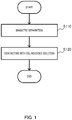
- FIG. 1 is a flowchart of a method according to the first embodiment of the present invention, for eluting Ca from steelmaking slag.
- the method according to the present embodiment for eluting Ca from steelmaking slag includes a step of subjecting the steelmaking slag to magnetic separation (Step S110: hereinafter also referred to as “magnetic separation step”); and a step of bringing the steelmaking slag subjected to the magnetic separation into contact with a CO 2 aqueous solution (Step S120: hereinafter also referred to as "contact step”).
- Step S110 steelmaking slag is subjected to magnetic separation
- Any steelmaking slag may be used as long as the steelmaking slag is discharged during a steel making process.
- the steelmaking slag include converter slag, pretreatment slag, secondary refining slag and electric furnace slag.
- Steelmaking slag discharged during a steel making process may be used as it is, or steelmaking slag fractured after the discharging may be used.
- the fractured slag particles preferably have a maximum particle diameter such that the size of the particles becomes the same as or smaller than the structure of the iron-based compound, and preferably of 1,000 ⁇ m or less (hereinafter, the particles are also simply referred to as "slag particles," and simply referred “steelmaking slag” includes both the fractured particles and non-fractured steelmaking slag).
- the maximum particle diameter of 1,000 ⁇ m or less allows the iron-based compound to exist as a single particle, and thus the iron-based compound is more likely to be selectively captured.
- Slag particles with the maximum particle diameter of 1,000 ⁇ m or less have a larger surface area per volume, and allow water or a CO 2 aqueous solution to satisfactorily permeate through the steelmaking slag. This enables elution of a larger amount of Ca in a below-described contact step. Any conventional crusher can fracture steelmaking slag until the maximum particle diameter thereof falls within the above range.
- the maximum particle diameter of the slag particles is preferably 500 ⁇ m or less, more preferably 250 ⁇ m or less and even more preferably 100 ⁇ m or less.
- the maximum particle diameter of the slag particles can be reduced to fall within the above range by, for example, further fracturing the fractured slag particles using a crusher, such as a hammer mill, a roller mill or a ball mill.
- the steelmaking slag is preferably subjected to heat treatment before the magnetic separation. Subjecting the steelmaking slag to the heat treatment increases the magnetization of iron-based compound and metal iron, and thus a larger amount of the iron-based compound can be removed by the magnetic separation.
- the heat treatment is preferably performed at a temperature of 300°C or more and 1,000°C or less for 0.01 minute or more and 60 minutes or less.
- steelmaking slag may be in a dried state, but preferably is slurry dispersed in water.
- Slug particles in the slurry-formed steelmaking slag are easily dispersed by, for example, the polarity of water molecules and/or a water flow, and thus the iron-based compound and metal iron are more likely to be selectively captured by a magnetic force.
- slag particles having the particle diameter of 1,000 ⁇ m or less are more likely to agglomerate in a gas, such as the air by the electrostatic force between the slag particles, liquid bridge by agglomerated water vapor or the like, but are satisfactorily dispersed in slurry.
- metal iron in steelmaking slag is minute, capturing the metal iron in dried steelmaking slag is difficult, but metal iron dispersed in water of the slurry-formed steelmaking slag can be captured more easily by magnetic separation.
- remaining-after-filtration slag may be used, which is obtained by placing steelmaking slag into a container including water therein, and leaching free lime, calcium hydroxide, and Ca on the top surface of Ca compounds, followed by filtration.
- Using the remaining-after-filtration slag means using slag from which Ca has been partly eluted, and thus a load on a below-described contact step can be reduced.
- filtered water which contains leached Ca is a highly alkaline aqueous solution having a pH of 11 or more (hereinafter, also simply referred to as "slag-immersed water").
- the slag-immersed water can be used for precipitation of a solid component containing Ca (precipitation step) during the recovery of Ca, as described below.
- the slag-immersed water can also be used in applications that require an alkaline aqueous solution, such as a neutralizer for acidic waste water. Further, subjecting the remaining-after-filtration slag to hydration treatment by below-described still standing with contained water gives advantages such that kneading with water is not necessary.
- the magnetic separation may be performed by any conventional magnetic separator.
- the magnetic separator may be a wet type or a dry type, and can be selected in accordance with the state of the steelmaking slag (in a dried state or a slurry form).
- the magnetic separator can be appropriately selected from a drum type, a belt type, a flowing-between-fixed-magnets type and the like.
- the drum type magnetic separator is preferable as handling of the slurry-formed steelmaking slag is easy and the magnetic separation amount can be easily increased by increasing the magnetic force in the drum type magnetic separator.
- the magnet used in the magnetic separator maybe a permanent magnet or an electromagnet.
- the magnetic flux density of a magnet may be at least at a level such that iron-based compounds and metal iron can be selectively captured from other compounds contained in steelmaking slag, and, for example, 0.003T or more and 0.5T or less, preferably 0.005T or more and 0.3T or less, and more preferably 0.01T or more and 0.15T or less.
- the magnetic separation is not necessarily performed until all the iron-based compounds contained in the steelmaking slag are removed. Even if the magnetic separation removes only a small amount of iron-based compounds from steelmaking slag, the present invention can provide the effect, namely easier elution of Ca into a CO 2 aqueous solution compared to conventional methods. Accordingly, the period of time, number and the like of the magnetic separation(s) may be appropriately selected in accordance with, for example, effects of the magnetic separation on the production cost.
- the steelmaking slag in a solid or slurry form after the removal of iron-based compounds and metal iron by the magnetic separation may be used for a contact step as it is; however, steelmaking slag in a slurry form is preferably separated into steelmaking slag and a liquid component by solid-liquid separation.
- the solid-liquid separation may be performed by any conventional method, such as vacuum filtration or pressure filtration.
- the liquid component obtained by the solid-liquid separation (hereinafter, also simply referred to as a "magnetic-separation water”) becomes alkaline as the magnetic-separation water contains Ca eluted from the steelmaking slag in addition to water used for forming the slurry.
- the liquid component can be used for a below-described step of increasing the pH of a CO 2 aqueous solution which has been in contact with steelmaking slag and thus includes Ca eluted therein, during the precipitation of the eluted Ca.
- the magnetic-separation-removed slag which is removed from steelmaking slag by the magnetic separation contains a large amount of Fe-containing compounds, such as iron-based compounds and metal iron as described above, and thus can be reused as a source for a blast furnace or sintering.
- steelmaking slag is brought into contact with a CO 2 aqueous solution. Specifically, the steelmaking slag is immersed in the CO 2 aqueous solution to elute Ca contained in the steelmaking slag into the aqueous solution (Step S120).
- the steelmaking slag may be immersed in water in which carbon dioxide is previously dissolved, or the steelmaking slag may be immersed in water followed by the dissolution of carbon dioxide in the water, in the present step.
- the steelmaking slag and the CO 2 aqueous solution are stirred for accelerating reactions.
- Carbon dioxide can be dissolved in water by, for example, bubbling (blowing) a gas containing carbon dioxide. It is preferred that 30 mg/L or more of non-ionized carbon dioxide (free carbonate) is dissolved in the CO 2 aqueous solution for increasing elution of Ca from the steelmaking slag.
- the amount of free carbonate that may be contained in tap water in general is 3 mg/L or more and 20 mg/L or less.
- the gas containing carbon dioxide may be pure carbon dioxide gas, or a gas containing carbon dioxide and components, such as oxygen and nitrogen in addition.
- gases containing carbon dioxide include an exhaust gas after combustion, and a mixed gas of carbon dioxide, air and water vapor.
- the gas containing carbon dioxide preferably contains carbon dioxide in high concentration (e.g. 90%).
- the amount of carbon dioxide in the CO 2 aqueous solution decreases with the dissolution of Ca since Ca reacts with carbon dioxide and forms water-soluble calcium hydrogen carbonate. Therefore, it is preferred to keep providing carbon dioxide to the CO 2 aqueous solution after the steelmaking slag is immersed in the CO 2 aqueous solution.
- the amount of the steelmaking slag in a CO 2 aqueous solution is preferably 1 g/L or more or 100g/L or less, and more preferably 2 g/L or more or 40 g/L or less.
- the immersion is performed preferably for three minutes or more, and more preferably for five minutes or more, for satisfactorily eluting Ca contained in the steelmaking slag.
- the first embodiment is capable of easier elution of Ca compounds contained in steelmaking slag into a CO 2 aqueous solution, and thus a larger amount of Ca can be eluted into the CO 2 aqueous solution in a shorter period of time.
- the first embodiment can be performed easily, and thus the costs during the actual performance of the embodiment can be reduced.
- the contact step may be a step (hereinafter, also referred to as a "modified contact step") of bringing steelmaking slag subjected to the magnetic separation into contact with an aqueous solution containing carbon dioxide while fracturing or pulverizing the steelmaking slag, or grinding the surface of the steelmaking slag (hereinafter, also collectively and simply referred to as a "fracturing or the like").
- modify contact step a step of bringing steelmaking slag subjected to the magnetic separation into contact with an aqueous solution containing carbon dioxide while fracturing or pulverizing the steelmaking slag, or grinding the surface of the steelmaking slag.
- the elution of Ca from steelmaking slag occurs upon contact of Ca compounds or Ca with a CO 2 aqueous solution in the vicinity of the surface of the steelmaking slag or inside the steelmaking slag. Therefore, during the contacting of steelmaking slag with a CO 2 aqueous solution, subjecting the steelmaking slag in contact with the CO 2 aqueous solution to fracturing or the like increases the surface area of slag particles that can be in contact with the CO 2 aqueous solution, and thus it becomes possible to bring a larger amount of Ca into contact with the CO 2 aqueous solution, or to increase the amount of the CO 2 aqueous solution permeating through the inside of the slag particles.
- components contained in the steelmaking slag dissolve in the CO 2 aqueous solution, for example, Fe, Al, Si and/or Mn, and/or hydroxides, carbonates and/or hydrates thereof may remain or be precipitated on the surface of the steelmaking slag.
- the remaining or precipitated substances prevent the steelmaking slag from contacting the CO 2 aqueous solution, Ca becomes less likely to be eluted from the inside of the steelmaking slag.
- grinding the surface of the steelmaking slag removes the remaining or precipitated substances to increase the contact area between the CO 2 aqueous solution and the slag particles and allow the CO 2 aqueous solution to permeate more easily through the steelmaking slag.
- steelmaking slag is immersed in a CO 2 aqueous solution, and at the same time, a conventional crusher usable in a wet method is used, thereby fracturing the immersed steelmaking slag.
- slag particles may be subjected to pulverizing and at the same time to fracturing or the like in a CO 2 aqueous solution by rotating a ball mill charged with the slag particles, the CO 2 aqueous solution and pulverizing balls.
- the present step is preferably continued until the maximum particle diameter of the slag particles becomes 1,000 ⁇ m or less, preferably 500 ⁇ m or less, more preferably 250 ⁇ m or less, and even more preferably 100 ⁇ m or less, for increasing the elution amounts of calcium.
- the modification of the first embodiment is capable of eluting a larger amount of Ca into the CO 2 aqueous solution in an even shorter period of time.
- the present modification can be performed easily, and thus the costs during the actual performance of the modification can be reduced.
- each of FIGS. 2 to 5 is a flowchart of a method according to another embodiment of the present invention, for eluting Ca from steelmaking slag.
- each method according to the present embodiment for eluting Ca from steelmaking slag includes a step of subjecting steelmaking slag to magnetic separation (Step S110: magnetic separation step); at least one of steps of subjecting the steelmaking slag to hydration treatment (Steps S130-1 to S130-5: hereinafter also referred to as "hydration step” each); and bringing the steelmaking slag subjected to the magnetic separation and hydration treatment into contact with a CO 2 aqueous solution (Step S120: contact step).
- the description for the magnetic separation step and contact step is omitted in the present embodiment as these steps can be performed in the same manner as in the above described first embodiment.
- the present step may be performed after the magnetic separation step as illustrated in FIG. 2 , before the magnetic separation step as illustrated in FIG. 3 , before and after the magnetic separation step as illustrated in FIG. 4 , or simultaneously with the magnetic separation step as illustrated in FIG. 5 .
- the hydration step may be performed before and simultaneously with the magnetic separation step, simultaneously with and after the magnetic separation step, or before, simultaneously with and after the magnetic separation step.
- the hydration step may be repeated more than once, for example, before, after and/or simultaneously with the magnetic separation step.
- steelmaking slag contains Ca in the forms of, for example, free lime, calcium hydroxide (Ca(OH) 2 ), calcium carbonate (CaCO 3 ), calcium silicate (such as Ca 2 SiO 4 or Ca 3 SiO 5 ) and calcium iron aluminum oxide (Ca 2 (Al 1-X Fe X ) 2 O 5 ).
- Ca(OH) 2 calcium silicate hydrates and calcium hydroxide (Ca(OH) 2 ) from calcium silicate by the reaction represented by the following equation 1
- hydroxides of calcium oxides from calcium iron aluminum oxide by the reaction represented by the following equation 2 hereinafter, compounds containing calcium, which can be obtained by the hydration treatment are also collectively referred to as "Ca hydrates": 2(2CaO ⁇ SiO 2 ) + 4H 2 O ⁇ 3CaO ⁇ 2SiO 2 ⁇ 3H 2 O + Ca(OH) 2 ...
- Equation 1 2CaO ⁇ 1/2(Al 2 O 3 ⁇ Fe 2 O 3 ) + 10H 2 O ⁇ 1/2(4CaO ⁇ Al 2 O 3 ⁇ 19H 2 O) + HFeO 2 ...
- Equation 2 is an example in which X is 1/2 in calcium iron aluminum oxide (Ca 2 (Al 1-X Fe X ) 2 O 5 )).
- the Ca hydrates generated, for example, by the above reactions easily dissolve in a CO 2 aqueous solution. Subjecting steelmaking slag to hydration treatment thus makes it possible to elute Ca derived from, for example, calcium silicate and calcium iron aluminum oxide contained in the steelmaking slag more easily.
- the free lime which is easily dissolved in a CO 2 aqueous solution, typically exists in steelmaking slag only in an amount of less than about 10 mass%.
- calcium silicate and calcium iron aluminum oxide typically exists in steelmaking slag in an amount of about 25 mass% to 70 mass%, and about 2 mass% to 30 mass%, respectively. Therefore, when the hydration treatment can elute Ca contained in, for example, calcium silicate and calcium iron aluminum oxide into a CO 2 aqueous solution more easily, the amount of Ca eluted from steelmaking slag into the CO 2 aqueous solution may increase, and it is possible to shorten the time for recovering Ca from the steelmaking slag.
- the total volume of compounds generated by the hydration treatment is usually larger than the total volume of the corresponding compounds before the reaction.
- free lime in the steelmaking slag is partly eluted into water used for the treatment.
- Subjecting steelmaking slag to hydration treatment thus generates cracks inside slag particles, and the slag particles are more likely to disintegrate from these cracks.
- Such disintegration of the slag particles reduces the particle diameter of the slag particles, and increases the surface area per volume thereof, as well as allowing water or a CO 2 aqueous solution to satisfactorily permeate through the steelmaking slag. This enables hydration of a large amount of Ca compounds in the present step, and elution of a larger amount of Ca in the contact step.
- Hydration treatment may be performed by a method and under conditions which can hydrate any Ca compound contained in steelmaking slag, preferably calcium silicate or calcium iron aluminum oxide.
- hydration treatment examples include, for example, the following methods: leaving steelmaking slag which is immersed and sunk in water to stand (hereinafter, also simply referred to as a "immersion and still standing”); stirring steelmaking slag immersed in water (hereinafter, also simply referred to as a “immersion and stirring”); leaving a paste containing slag particles and water to stand (hereinafter, also simply referred to as a “still standing in paste form”); and leaving steelmaking slag to stand in a container including a satisfactory amount of water vapor (hereinafter, also simply referred to as a "still standing in wet condition”). Any one of these methods can satisfactorily contact steelmaking slag with water.
- the hydration treatment may be performed by only one of the methods, namely the immersion and still standing, the immersion and stirring, the still standing in paste form, the still standing in wet condition and the like, or by two or more of the above methods in any order.
- the relative humidity is preferably 70% or more for ensuring satisfactory condensing water vapor between slag particles by capillary condensation to allow water reach the slag particles.
- the slurry-formed steelmaking slag may be in contact with water for a long period of time by, for example, performing the magnetic separation in a wet method for a long period of time, or circulating the slurry when subjecting to the magnetic separation in a wet method.
- the slurry may be immersed and stirred in a tank provided on a circulation path.
- water used therefor preferably contains less than 300 mg/l of carbon dioxide including, for example, non-ionized free carbonate, and ionized hydrogen carbonate ions (HCO 3 - ).
- carbon dioxide content being less than 300 mg/l, Ca compounds other than free lime and calcium hydroxide are less likely to be eluted into the water used for the hydration treatment, and thus most of Ca contained in steelmaking slag can be eluted into the CO 2 aqueous solution in the contact step, which less likely complicates a Ca recovery process.
- the water used for the hydration treatment may have a temperature at which the water is not violently evaporated at the most.
- the temperature of the water is preferably 100°C or less when steelmaking slag is subjected to the hydration treatment at substantially atmospheric pressure.
- the water temperature may be more than 100°C, as long as the temperature is lower than the boiling point of the water under the pressure applied during the hydration treatment.
- the water temperature during the hydration treatment performed by the immersion and still standing, or the immersion and stirring is preferably 0°C or more and 80°C or less. While there is no limitation to the upper limit of the water temperature when performing the hydration treatment under a higher pressure by using, for example, an autoclave, a temperature of 300°C or less is preferred from the view point of the pressure resistance property of an apparatus, and in an economical aspect.
- the temperature during the performance of the hydration treatment by the still standing in paste form is preferably 0°C or more and 70°C or less.
- the relative humidity may be increased by introducing water vapor into a gas, such as air, nitrogen (N 2 ), oxygen (O 2 ), argon (Ar) or helium (He), or a gas composed only of water vapor may be used.
- a gas such as air, nitrogen (N 2 ), oxygen (O 2 ), argon (Ar) or helium (He), or a gas composed only of water vapor may be used.
- the relative humidity and temperature in the container may be set to any values
- the temperature of a gas at which water vapor is introduced under, for example, substantially atmospheric pressure may be 0°C or more and 100°C or less, preferably 10°C or more and 100°C or less, and the relative humidity of the gas may be 70% or more.
- the gas may be stirred for more uniform hydration of Ca compounds.
- the water vapor pressure is set to the atmospheric pressure or more
- the water vapor temperature may be, for example, 100°C or more.
- a temperature of 300°C or less is preferred from the view point of the pressure resistance property of an apparatus, and in an economical aspect.
- the duration of the hydration treatment may be set to any period of time in accordance with, for example, the average particle size of the slag and the temperature during the hydration treatment (the temperature of water or air containing water vapor).
- the average particle size of the slag and the temperature during the hydration treatment the temperature of water or air containing water vapor.
- the duration of the hydration treatment may be about 8 hours without interval, preferably 3 hours or more and 30 hours or less.
- the duration of the hydration treatment is preferably 0.6 hours or more and 8 hours or less, without interval.
- the duration of the hydration treatment may be about 7 hours without interval, preferably 3 hours or more and 30 hours or less.
- the duration of the hydration treatment is preferably 0.5 hours or more and 8 hours or less without interval.
- the duration of the hydration treatment may be about 10 hours without interval, preferably 1 hour or more and 40 hours or less.
- the duration of the hydration treatment is preferably 0.2 hours or more and 5 hours or less without interval.
- Predetermined average particle size of steelmaking slag and conditions for the hydration treatment e.g., temperature and duration
- the Ca recovery rate for example, no higher recovery rate can be obtained
- the hydration treatment is preferably continued until calcium silicate satisfactorily becomes hydrates and calcium hydroxide, and/or calcium iron aluminum oxide satisfactorily becomes hydroxides of calcium oxides.
- the hydration treatment is, for example, preferably continued until the amount of calcium silicate or calcium iron aluminum oxide contained in steelmaking slag becomes 50 mass% or less, or 20 mass% or less, respectively.
- the steelmaking slag in a solid or slurry form after subjected to the hydration treatment may be used for the contact step as it is; however, when the hydration treatment is performed by the immersion and still standing, the immersion and stirring, or the still standing in paste form, the steelmaking slag subjected to the hydration treatment is preferably separated into steelmaking slag and a liquid component by solid-liquid separation.
- the solid-liquid separation may be performed by any conventional method, such as vacuum filtration or pressure filtration.
- the liquid component obtained by the solid-liquid separation (hereinafter, also simply referred to as a "hydration-treatment water”) becomes alkaline as the hydration-treatment water contains Ca eluted from the steelmaking slag.
- the liquid component can be used for a below-described step of increasing the pH of a CO 2 aqueous solution, which has been in contact with steelmaking slag and thus includes Ca eluted therein, during the precipitation of the eluted Ca.
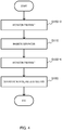
- FIG. 2 is a flowchart illustrating a method according to the first mode of the present embodiment, for eluting Ca from steelmaking slag.
- the magnetic separation step (Step S110), the hydration step (Step S130-1) and the contact step (Step S120) are performed in this order in the present mode.
- the hydration treatment performed on steelmaking slag in the hydration step may be any one of the immersion and still standing, the immersion and stirring, the still standing in paste form and the still standing in wet condition; however, for simplifying subsequent steps by simultaneously performing the hydration treatment and the solid-liquid separation, the immersion and still standing or the still standing in paste form is preferred.
- the magnetic separation reduces the volume of steelmaking slag, and therefore, performing the hydration step (Step S130-1) after the magnetic separation step (Step S110) can subject the steelmaking slag to the hydration treatment more effectively.
- FIG. 3 is a flowchart illustrating a method according to the second mode of the present embodiment, for eluting Ca from steelmaking slag.
- the hydration step (Step S130-2), the magnetic separation step (Step S110), and the contact step (Step S120) are performed in this order in the present mode.
- the hydration treatment performed on steelmaking slag in the hydration step may be any one of the immersion and still standing, the immersion and stirring, the still standing in paste form and the still standing in wet condition; however, for dispersing agglomerated slurry particles, thereby more selectively capturing iron-based compounds and metal iron in the following magnetic separation step (Step S110), the immersion and stirring is preferred.
- FIG. 4 is a flowchart illustrating a method according to the third mode of the present embodiment, for eluting Ca from steelmaking slag.
- the hydration step (Step S130-3), the magnetic separation step (Step S110), the hydration step (Step S130-4), and the contact step (Step S120) are performed in this order in the present mode.
- the hydration treatment performed on steelmaking slag in the hydration steps may be any one of the immersion and still standing, the immersion and stirring, the still standing in paste form and the still standing in wet condition.
- the hydration treatment performed on steelmaking slag in the hydration step (Step S130-3) before the magnetic separation is preferably the immersion and stirring for dispersing agglomerated slurry particles, thereby more selectively capturing iron-based compounds and metal iron in the following magnetic separation step (Step S110).
- the hydration treatment performed on steelmaking slag in the hydration step (Step S130-4) after the magnetic separation is preferably the immersion and still standing or the still standing in paste form for simplifying subsequent steps by simultaneously performing the hydration treatment and the solid-liquid separation.
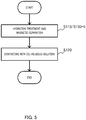
- FIG. 5 is a flowchart illustrating a method according to the fourth mode of the present embodiment, for eluting Ca from steelmaking slag. As illustrated in FIG. 5 , the hydration step and the magnetic separation step are simultaneously performed (Step S110/S130-5), followed by the contact step (Step S120) in the present mode.
- the hydration step and the magnetic separation step can be simultaneously performed by subjecting slurry-formed steelmaking slag to the magnetic separation for the period of time sufficient for satisfactorily hydrating Ca compounds contained in the steelmaking slag, particularly calcium silicate that is difficult to capture by the magnetic separation. For example, about one hour of magnetic separation on slurry-formed steelmaking slag can simultaneously perform the hydration treatment and the magnetic separation.
- the immersion and still standing or the immersion and stirring may be performed in a storage tank by circulating the slurry between the magnetic separator and the storage tank at a circulation rate adjusted so that the flow rate of the slurry in the tank becomes satisfactorily slow.
- the second embodiment is capable of hydrating Ca compounds contained in steelmaking slag, particularly calcium silicate and calcium iron aluminum oxide, to generate Ca hydrates which can be eluted into a CO 2 aqueous solution more easily, and thus a larger amount of Ca can be eluted into the CO 2 aqueous solution in a shorter period of time.
- the hydration treatment in the second embodiment can be performed easily, and thus the costs during the actual performance of the embodiment can be reduced.
- the immersed steelmaking slag may be subjects to the fracturing or the like at the same time (hereinafter also referred to as "modified hydration step").
- Reactions during the above described hydration treatment occur upon contact of Ca compounds with water in the vicinity of the surface of the steelmaking slag or inside the steelmaking slag. While water permeates through the steelmaking slag to some extent, a larger amount of water contacts the vicinity of the surface. Ca hydrates is thus more likely to be generated in the vicinity of the surface of the steelmaking slag.
- components contained in the steelmaking slag dissolve in the water used for the hydration treatment, for example, Fe, Al, Si and Mn, and/or hydroxides, carbonates and/or hydrates thereof may remain or be precipitated on the surface of the steelmaking slag, as in the above described case of dissolution into a CO 2 aqueous solution.
- Ca hydrates becomes less likely to be generated inside the steelmaking slag.
- Subjecting the steelmaking slag immersed in water to fracturing or the like during the hydration treatment increases the surface area of slag particles, thereby increasing the contact area between the water and the slag particles.
- Subjecting the steelmaking slag immersed in water to fracturing or the like also continuously forms new surfaces where the above described substances do not remain or are not precipitated, and water can permeate through the steelmaking slag from the continuously formed new surfaces, and therefore, Ca hydrates becomes more likely to be generated even inside the steelmaking slag.
- grinding the surface of the steelmaking slag removes the remaining or precipitated substances to increase the contact area between the water and the slag particles and allow water to permeate more easily through the steelmaking slag.
- steelmaking slag is immersed in water, and at the same time, a conventional crusher usable in a wet method is used, thereby fracturing the immersed steelmaking slag.
- a conventional crusher usable in a wet method is used, thereby fracturing the immersed steelmaking slag.
- performing the hydration treatment and pulverizing slag particles in water at the same time by rotating a ball mill charged with the slag particles, water and pulverizing balls.
- the present step can easily elute Ca more quickly in an amount the same or more as compared to the above embodiment including the first step.
- the duration of the present step is preferably 0.1 hour or more and 5 hours or less, and more preferably 0.2 hours or more and 3 hours or less, without interval.
- the present step is preferably continued until the maximum particle diameter of the slag particles becomes 1,000 ⁇ m or less, preferably 500 ⁇ m or less, more preferably 250 ⁇ m or less, and even more preferably 100 ⁇ m or less. Therefore, the present step can be performed simultaneously with the fracturing steelmaking slag or pulverizing slag particles without complicating the steps.
- performing the modified hydration step in place of the hydration step can reduce the particle diameter of steelmaking slag to fall within the above range while performing the hydration treatment, and thus the load on the fracturing or the like of the steelmaking slag can also be reduced.
- the first modification is capable of eluting a larger amount of Ca into a CO 2 aqueous solution in an even shorter period of time.
- the present modification can be performed without complicating the steps, such as being performed simultaneously with the fracturing steelmaking slag or the pulverizing slag particles, and thus the costs during the actual performance of the embodiment can be reduced.
- the contact step may also be a step (modified contact step) of bringing steelmaking slag subjected to the magnetic separation into contact with an aqueous solution containing carbon dioxide while subjecting the steelmaking slag to the fracturing or the like.
- the second modification of the second embodiment is capable of eluting a larger amount of Ca into the CO 2 aqueous solution in an even shorter period of time.
- the present modification can be performed easily, and thus the costs during the actual performance of the modification can be reduced.
- FIG. 6 is a flowchart of a method according to the third embodiment of the present invention for recovering Ca eluted in a CO 2 aqueous solution. As illustrated in FIG. 6 , the present embodiment includes a step of eluting Ca (Step S100) and a step of recovering Ca (Step S200).
- Step S100 In the step of eluting Ca (Step S100), Ca is eluted from steelmaking slag. Any one of the above described first and second embodiments and modifications thereof is capable of eluting Ca.
- FIG. 7 is a flowchart illustrating an exemplary step of recovering Ca (Step S200).
- the step of recovering Ca includes for its performance, for example, a step of separating steelmaking slag from a CO 2 aqueous solution (Step S210 hereinafter also referred to as “separation step"), a step of precipitating Ca (Step S220: hereinafter also referred to as “precipitation step”), and a step of recovering a precipitated solid component (Step S230: hereinafter also referred to as "recovery step”).
- steelmaking slag is separated from a CO 2 aqueous solution (supernatant) having Ca dissolved therein (Step S210).
- the separation may be performed by any conventional method. Examples of separating methods include filtration, and a method in which the steelmaking slag settles out by leaving the CO 2 aqueous solution to stand. In the case where the slag settles out, only the supernatant may further be recovered, or subsequent steps may be performed only on the supernatant in a two-component system containing the supernatant and the steelmaking slag that settles out, as long as a solid component precipitated in a subsequent step is not mixed with the steelmaking slag.
- the present step becomes unnecessary when the steelmaking slag has already been separated from the CO 2 aqueous solution in the contact step.
- Ca eluted into the CO 2 aqueous solution is precipitated as a solid component containing Ca (Step S220).
- Ca eluted into the CO 2 aqueous solution can be precipitated by any conventional method.
- Examples of the methods for precipitating Ca eluted in a CO 2 aqueous solution as a solid component include a method that removes carbon dioxide from the CO 2 aqueous solution, and a method that increases the pH of the CO 2 aqueous solution.
- Ca eluted into a CO 2 aqueous solution in the contact step can be precipitated by, for example, removing carbon dioxide from the CO 2 aqueous solution separated from steelmaking slag in the separation step (Step S210).
- Examples of Ca compounds to be precipitated in this procedure include calcium carbonate, calcium carbonate hydrate and calcium hydroxide.
- Any method for removing carbon dioxide from a CO 2 aqueous solution can be employed.
- the methods for removing carbon dioxide include (1) gas introduction, (2) pressure reduction and (3) heating.
- Carbon dioxide can be removed from a CO 2 aqueous solution having Ca dissolved therein by introducing into the CO 2 aqueous solution a gas having a partial pressure of carbon dioxide lower than the equilibrium pressure of carbon dioxide dissolved in the CO 2 aqueous solution to replace the dissolved carbon dioxide by the introduced gas, or to diffuse (transfer) carbon dioxide into bubbles of the introduced gas.
- the gas to be introduced may be a gas reactive to water (such as chlorine and sulfur dioxide)
- a gas having low reactivity to water is preferred for suppressing the reduction of the precipitated Ca amount due to the formation of salts from the eluted calcium and ions generated by the introduction of a gas reactive to water into the CO 2 aqueous solution.
- the gas to be introduced into the CO 2 aqueous solution may be an inorganic gas or an organic gas.
- An inorganic gas is more preferred since the possibility of combustion or explosion is low when the gas leaks outside.
- Examples of the inorganic gases having low reactivity to water include air, nitrogen, oxygen, hydrogen, argon, helium and mixed gases thereof.
- An example of the mixed gas is air in the environment where the present step is performed, which contains nitrogen and oxygen in an approximate ratio of 4 to 1.
- Examples of the organic gases having low reactivity to water include methane, ethane, ethylene, acetylene, propane and fluorocarbons.
- carbon dioxide can be removed from the CO 2 aqueous solution by placing the CO 2 aqueous solution under a reduced-pressure environment.
- carbon dioxide can be removed by putting the CO 2 aqueous solution into an airtight container and evacuating air (degassing) of the container using, e.g., a pump to allow the container to have a reduced-pressure atmosphere.
- the pressure reduction may be simultaneously performed with applying ultrasonic waves to the CO 2 aqueous solution or stirring the CO 2 aqueous solution.
- the solubility of carbon dioxide decreases when the temperature of a CO 2 aqueous solution increases. Therefore, carbon dioxide can be removed from the CO 2 aqueous solution by heating the CO 2 aqueous solution.
- the CO 2 aqueous solution is preferably heated to a temperature within such a range that the vapor pressure of the solution does not exceed the pressure in the atmosphere.
- the heating temperature is preferably less than 100°C. Heating the CO 2 aqueous solution not only removes carbon dioxide, but also lowers the solubility of Ca compounds (e.g., calcium carbonate), and thus Ca can be precipitated more easily.
- the above methods (1) to (3) may be performed in a combination for further increasing the amount of removed carbon dioxide.
- the most suitable combination can be selected in view of, for example, a delivery system of a gas or heat, a site location, or availability of a by-product gas in a factory.
- the gas introduction can provide effects of removing carbon dioxide and stirring, and the pressure reduction of the CO 2 aqueous solution can provide an effect of removing carbon dioxide, and thus carbon dioxide can be removed effectively.
- Heating in addition to this procedure can further accelerate removal effects of carbon dioxide. Since carbon dioxide can be easily removed due to the additive effects of the gas introduction into the CO 2 aqueous solution and pressure reduction of the CO 2 aqueous solution, the heating temperature is not necessarily high, and thus heating costs can be reduced.
- FIG. 8 shows the existence ratio of each of ions and substances.
- [H 2 CO 3 *] represents the total amount of [CO 2 ] and [H 2 CO 3 ]. It can be considered from FIG.
- the pH of the CO 2 aqueous solution separated from the steelmaking slag in the separation step is increased preferably by 0.2 or more, more preferably by 0.3 or more, still more preferably by 1.0 or more, even more preferably by 1.5 or more, and particularly preferably by 2.0 or more.
- the pH of the CO 2 aqueous solution is preferably increased while measuring the same.
- the pH of the CO 2 aqueous solution can be measured by any conventional glass electrode method.
- the phosphorus compounds recovered from steelmaking slag can be reused as a phosphorus source. Therefore, recovery of the solid component with a high content of the phosphorus compounds enables easy reuse of phosphorus.
- Ca compounds recovered from steelmaking slag can be reused as iron-making materials, produced iron would become brittle when the iron-making materials contain phosphorus compounds.
- the content of the phosphorus compounds in the solid component for reuse as an iron-making material is thus preferably low.
- the early stage precipitate is recovered before the pH increases by preferably 1.0, more preferably 0.6, and still more preferably 0.4.
- the pH of a CO 2 aqueous solution can be increased by, for example, adding an alkaline substance into the CO 2 aqueous solution.
- alkaline substances that can be fed into the CO 2 aqueous solution include calcium hydroxide, ammonia and sodium hydroxide.
- Calcium hydroxide, ammonia or sodium hydroxide can be fed by dissolving the same in water, and adding the resultant solution to the CO 2 aqueous solution.
- Calcium hydroxide, ammonia and sodium hydroxide each may be a commercial product, or a substance contained in a liquid such as a waste fluid.
- a waste fluid generated during the production of acetylene by reacting, e.g., calcium carbide with water can be added to the CO 2 aqueous solution.
- the slag-immersed water provided by immersing steelmaking slag into water, the above described magnetic-separation water or hydration-treatment water may be added to the CO 2 aqueous solution.
- the slag-immersed water, magnetic-separation water and hydration-treatment water may be obtained by subjecting the steelmaking slag from which calcium is to be recovered or alternatively another steelmaking slag to immersion into water, magnetic separation or hydration treatment, respectively.
- calcium hydroxide a waste fluid mostly composed of calcium hydroxide, the slag-immersed water, the magnetic-separation water or the hydration-treatment water is preferred for use.
- These contain mostly calcium hydroxide, and therefore using the same can reduce the amount of unnecessary substances, such as ammonia and sodium, mixed in the obtained calcium compounds.
- unnecessary substances such as ammonia and sodium
- an aqueous solution after the recovery of Ca therefrom (former CO 2 aqueous solution) by the method according to the present embodiment allows waste water treatment to become simpler or unnecessary, thereby suppressing the waste water treatment cost.
- the aqueous solution after the recovery of Ca therefrom contains substantially no metallic elements, such as Ca, Fe, Mn, Al and P, and CO 2 , and thus can be reused in the same step, thereby achieving no waste water.
- removal of carbon dioxide may be performed in combination with the increasing pH.
- a solid component precipitated in the precipitation step (Step S220) is recovered (Step S230).
- the precipitated solid component can be recovered by any conventional method, such as vacuum filtration or pressure filtration.
- the solid component contains Ca derived from steelmaking slag.
- Steelmaking slag A and steelmaking slag B each having a component ratio as shown in Table 1 were prepared.
- the components of the steelmaking slag were measured by IPC optical emission spectrometry and chemical analysis.
- Steelmaking slag A and steelmaking slag B were pulverized using a hammer mill so that the average particle diameter thereof became 100 ⁇ m or less.
- the average particle diameter of the pulverized slag was confirmed using a laser diffraction/scattering type particle size distribution measuring device.
- [Table 1] Steelmaking Slug Component Ratio (mass%) Ca Fe Si Mn Mg Al P A 35.3 15.8 7.2 4.1 2.5 2.0 0.8 B 31.3 11.2 7.3 3.0 1.9 1.8 2.0
- Slag slurry was provided for each of steelmaking slag A and steelmaking slag B by dispersing the steelmaking slag into 50 times as much amount of water by mass ratio.
- Each obtained slag slurry was poured into the lower part of a drum type magnetic separator, which has a permanent magnet fixed on the bottom half of the rotating drum thereof, and the rotating drum was rotated at the peripheral speed of 3 m/min for 5 minutes.
- the slag magnetically attracted to the rotating drum was then recovered from the top.
- the magnetic flux density on the drum surface of the magnetic separator was set to 0.03T.
- the Fe content in the recovered slag was measured by the ICP spectrometry and chemical analysis.
- the Fe recovery rate (%) of the magnetic separation was calculated by dividing the measured Fe content in the recovered slag by the Fe content in the steelmaking slag used for the magnetic separation (steelmaking slag A or steelmaking slag B).
- the slag slurry that was not magnetically attracted during the magnetic separation was separated into steelmaking slag and water by pressure filtration.
- the separated water had a pH of 12.0 to 12.5, and thus was considered to contain Ca eluted from the steelmaking slag
- the amount of Ca contained in the separated water was measured by ICP spectrometry and chemical analysis.
- the elution rate (%) of Ca after the magnetic separation was calculated by dividing the measured Ca content in the separated water by the Ca content in the steelmaking slag used for the magnetic separation (steelmaking slag A or steelmaking slag B).
- each of steelmaking slag A and steelmaking slag B was dispersed in water, and separated into steelmaking slag and water by pressure filtration after 5 minutes. The amount of Ca contained in the separated water was then measured by ICP spectrometry and chemical analysis. The elution rate (%) of Ca upon contact with water was calculated by dividing the measured Ca content in the separated water by the Ca content in the steelmaking slag used for the contact with water (steelmaking slag A or steelmaking slag B).
- the steelmaking slag separated from the water was divided into two, and each half was brought into contact with a CO 2 aqueous solution by one of the following two methods.
- CO 2 contact 1 (without fracturing): 0.25 kg of the steelmaking slag separated from water after the magnetic separation was mixed with 50L of water and stirred while carbon dioxide was blown at the flow rate of 7 L/min at normal temperature (20 to 40°C), thereby eluting Ca.
- CO 2 contact 2 (with fracturing): a ball mill was charged with 0.25 kg of the steelmaking slag separated from water after the magnetic separation, 50L of water and 10L (apparent volume) of pulverizing balls having a ball diameter of 10 mm. Subsequently, the ball mill was rotated at a peripheral speed of 70 m/min to fracture the steelmaking slag while carbon dioxide was blown at the flow rate of 7 L/min at normal temperature (20 to 40°C), thereby eluting Ca.
- each steelmaking slag was separated from the CO 2 aqueous solution, and the amount (kg/50L) of Ca eluted into the CO 2 aqueous solution was measured by ICP spectrometry and chemical analysis.
- the elution rate (%) of Ca upon contact with the CO 2 aqueous solution was calculated by dividing the measured Ca amount by a value obtained from the mass of immersed steelmaking slag multiplied by the Ca component ratio in the steelmaking slag.
- steelmaking slag A or steelmaking slag B was dispersed in water and immediately separated into steelmaking slag and water by pressure filtration, the same treatment was performed on the separated steelmaking slag, and the Ca amount eluted into the aqueous solution containing carbon dioxide and the elution rate of Ca were measured in the same manner.
- Table 2 shows the types of steelmaking slag, whether the heat treatment and magnetic separation were performed, the Fe recovery rate in the magnetic separation, the Ca elution rate after the magnetic separation, the Ca elution rate upon contact with water, and the Ca elution rate upon contact with a CO 2 aqueous solution.
- Example 1 A - Yes 11 4 - 34 - Example 2 B - Yes 10 4 - 32 - Example 3 A - Yes 11 4 - - 51 Example 4 A Yes Yes 19 4 - - 57 Example 5 A Yes Yes 26 4 - - 61 Example 6 B - Yes 10 4 - - 50 Example 7 B Yes Yes 17 4 - - 58 Example 8 B Yes Yes 24 4 - - 60 Comparative Example 1 A - No - - 3 27 - Comparative Example 2 B - No - - 4 26 - Comparative Example 3 A - No - - 3 - 43 Comparative Example 4 B - No - - 3 - 40
- the magnetic separation of the slag slurry could have recovered 10% or more of Fe. All the compounds recovered during the procedure had the concentrations of Fe at 40 mass% or more, Mn at 5 mass% or more, and Mg at 1 mass% or more, as measured by the ICP spectrometry and chemical analysis, and thus can be reused in an iron-making process.
- Subjecting steelmaking slag to the heat treatment before the magnetic separation increased both the Fe recovery rate in the magnetic separation and the Ca elution rate upon contact with a CO 2 aqueous solution after the magnetic separation.
- Steelmaking slag A used in experiment 1 was prepared, and a part thereof was subjected to the heat treatment as in experiment 1.
- Slag slurry from each of steelmaking slag A not subjected to the heat treatment and steelmaking slag A subjected to the heat treatment was prepared as in experiment 1, and subjected to the magnetic separation as in experiment 1, followed by separation into steelmaking slag and water by pressure filtration.
- hydration treatment was performed before, simultaneously with, or after the magnetic separation by one of the following methods.
- the immersion and stirring was performed for 20 minutes, and the immersion and still standing for 40 minutes so that the total time of the hydration treatment became 60 minutes.
- the paste-formed steelmaking slag was placed in a container and stored therein for 60 minutes while ensuring that the steelmaking slag was not dried, and kept in a paste form.
- the magnetic separation was performed by circulating slag slurry between a magnetic separator and a tank where the slag slurry was stored before being poured into the magnetic separator, for 30 minutes of rotation time of the rotating drum. During the circulation, the circulation rate was adjusted so that the flow rate of the slag slurry in the tank became satisfactorily slow.
- each steelmaking slag was brought in contact with a CO 2 aqueous solution by the CO 2 contact 2 (with fracturing) described in experiment 1.
- Table 3 shows whether the heat treatment was performed, the types of hydration treatment performed before, simultaneously with, and after the magnetic separation, the Fe recovery rate in the magnetic separation, the Ca elution rate after the magnetic separation, and the Ca elution rate upon contact with the CO 2 aqueous solution.
- All the compounds recovered by the magnetic separation during the procedure also had the concentrations of Fe at 40 mass% or more, Mn at 5 mass% or more, and Mg at 1 mass% or more, as measured by the ICP spectrometry and chemical analysis, and thus can be reused in an iron-making process.
- the method according to the present invention for eluting Ca can easily increase the elution amount of Ca from steelmaking slag into an aqueous solution containing carbon dioxide, as well as the recovery rate of Ca from the steelmaking slag, and therefore is advantageous as a method for recovering a Ca source in an iron-making process.
Landscapes
- Chemical & Material Sciences (AREA)
- Engineering & Computer Science (AREA)
- Organic Chemistry (AREA)
- Materials Engineering (AREA)
- Metallurgy (AREA)
- Manufacturing & Machinery (AREA)
- Mechanical Engineering (AREA)
- Geology (AREA)
- Life Sciences & Earth Sciences (AREA)
- General Life Sciences & Earth Sciences (AREA)
- Environmental & Geological Engineering (AREA)
- Ceramic Engineering (AREA)
- Structural Engineering (AREA)
- Curing Cements, Concrete, And Artificial Stone (AREA)
- Furnace Details (AREA)
- Carbon Steel Or Casting Steel Manufacturing (AREA)
- Manufacture And Refinement Of Metals (AREA)
- Treatment Of Steel In Its Molten State (AREA)
- Refinement Of Pig-Iron, Manufacture Of Cast Iron, And Steel Manufacture Other Than In Revolving Furnaces (AREA)
Applications Claiming Priority (2)
| Application Number | Priority Date | Filing Date | Title |
|---|---|---|---|
| JP2017006614A JP6794842B2 (ja) | 2017-01-18 | 2017-01-18 | 製鋼スラグからカルシウムを溶出させる方法、および製鋼スラグからカルシウムを回収する方法 |
| PCT/JP2018/000837 WO2018135439A1 (ja) | 2017-01-18 | 2018-01-15 | 製鋼スラグからカルシウムを溶出させる方法、および製鋼スラグからカルシウムを回収する方法 |
Publications (1)
| Publication Number | Publication Date |
|---|---|
| EP3572533A1 true EP3572533A1 (de) | 2019-11-27 |
Family
ID=62909138
Family Applications (1)
| Application Number | Title | Priority Date | Filing Date |
|---|---|---|---|
| EP18741723.3A Withdrawn EP3572533A1 (de) | 2017-01-18 | 2018-01-15 | Verfahren zum eluieren von calcium aus schlacke aus der stahlherstellung und verfahren zum sammeln von calcium aus schlacke aus der stahlherstellung |
Country Status (11)
| Country | Link |
|---|---|
| US (1) | US20200318209A1 (de) |
| EP (1) | EP3572533A1 (de) |
| JP (1) | JP6794842B2 (de) |
| KR (1) | KR20180119637A (de) |
| CN (1) | CN108779505A (de) |
| BR (1) | BR112018069465A2 (de) |
| CA (1) | CA3018530A1 (de) |
| MX (1) | MX2018011805A (de) |
| RU (1) | RU2713885C1 (de) |
| TW (1) | TW201831697A (de) |
| WO (1) | WO2018135439A1 (de) |
Families Citing this family (12)
| Publication number | Priority date | Publication date | Assignee | Title |
|---|---|---|---|---|
| US20190078170A1 (en) * | 2016-03-24 | 2019-03-14 | Nisshin Steel Co., Ltd. | Method for eluting calcium from steel slag and method for recovering calcium from steel slag |
| JP2020045260A (ja) * | 2018-09-20 | 2020-03-26 | 日鉄日新製鋼株式会社 | 製鋼スラグからカルシウムを回収する方法 |
| JP7303430B2 (ja) * | 2019-06-28 | 2023-07-05 | 日本製鉄株式会社 | 回収方法 |
| CN110436807A (zh) * | 2019-08-22 | 2019-11-12 | 武汉钢铁有限公司 | 一种钢渣表面稳定化的处理方法 |
| JP7457303B2 (ja) | 2020-02-10 | 2024-03-28 | 国立大学法人京都大学 | カルシウムを含む固形分の回収方法 |
| JP7294207B2 (ja) * | 2020-03-27 | 2023-06-20 | 住友大阪セメント株式会社 | セメント原料の製造方法 |
| CN111558606B (zh) * | 2020-06-05 | 2021-10-29 | 瀜矿环保科技(上海)有限公司 | 基于二氧化碳的湿法冶金多级反应和分离系统 |
| TWI766691B (zh) * | 2021-05-20 | 2022-06-01 | 中國鋼鐵股份有限公司 | 電爐煉鋼的方法 |
| TWI808760B (zh) * | 2022-05-16 | 2023-07-11 | 中國鋼鐵股份有限公司 | 電爐煉鋼的方法 |
| WO2023223399A1 (ja) * | 2022-05-16 | 2023-11-23 | 日揮グローバル株式会社 | アルカリ土類金属の抽出方法、co2固定化方法、及びco2を固定化し有価金属を回収する方法 |
| CN115069362B (zh) * | 2022-05-30 | 2023-11-21 | 湖北工业大学 | 一种钢铁厂湿磨钢渣固碳减排的方法及应用 |
| TWI814460B (zh) * | 2022-06-27 | 2023-09-01 | 國立中興大學 | 塊狀脫硫劑的製備方法 |
Family Cites Families (8)
| Publication number | Priority date | Publication date | Assignee | Title |
|---|---|---|---|---|
| JPS5488894A (en) * | 1977-12-26 | 1979-07-14 | Kobe Steel Ltd | Converter slag treating method |
| JPS55100220A (en) * | 1979-01-19 | 1980-07-31 | Sumitomo Metal Ind Ltd | Recovering method for calcium carbonate in converter slag |
| RU2377324C2 (ru) * | 2008-01-09 | 2009-12-27 | Открытое акционерное общество "Чусовской металлургический завод" | Способ переработки металлургических шлаков и технологическая линия (варианты) для его осуществления |
| JP2010270378A (ja) * | 2009-05-22 | 2010-12-02 | Kobelco Eco-Solutions Co Ltd | 製鋼スラグからのリン回収方法 |
| US8540798B2 (en) * | 2011-01-04 | 2013-09-24 | Guilherme Santana Lopes Gomes | Systems and methods for recycling steelmaking converter sludge |
| WO2015114703A1 (ja) * | 2014-01-28 | 2015-08-06 | 日新製鋼株式会社 | リンおよびカルシウムの回収方法および前記回収方法によって得られる混合物 |
| JP6263144B2 (ja) * | 2015-03-23 | 2018-01-17 | 日新製鋼株式会社 | 製鋼スラグからカルシウムを含有する固体成分を回収する方法、および回収された固体成分 |
| US20190078170A1 (en) * | 2016-03-24 | 2019-03-14 | Nisshin Steel Co., Ltd. | Method for eluting calcium from steel slag and method for recovering calcium from steel slag |
-
2017
- 2017-01-18 JP JP2017006614A patent/JP6794842B2/ja active Active
-
2018
- 2018-01-15 US US16/089,991 patent/US20200318209A1/en not_active Abandoned
- 2018-01-15 CN CN201880001375.6A patent/CN108779505A/zh active Pending
- 2018-01-15 CA CA3018530A patent/CA3018530A1/en not_active Abandoned
- 2018-01-15 KR KR1020187028097A patent/KR20180119637A/ko not_active Application Discontinuation
- 2018-01-15 MX MX2018011805A patent/MX2018011805A/es unknown
- 2018-01-15 WO PCT/JP2018/000837 patent/WO2018135439A1/ja active Application Filing
- 2018-01-15 EP EP18741723.3A patent/EP3572533A1/de not_active Withdrawn
- 2018-01-15 BR BR112018069465-7A patent/BR112018069465A2/pt not_active IP Right Cessation
- 2018-01-15 RU RU2018131298A patent/RU2713885C1/ru not_active IP Right Cessation
- 2018-01-18 TW TW107101798A patent/TW201831697A/zh unknown
Also Published As
| Publication number | Publication date |
|---|---|
| CN108779505A (zh) | 2018-11-09 |
| TW201831697A (zh) | 2018-09-01 |
| WO2018135439A1 (ja) | 2018-07-26 |
| CA3018530A1 (en) | 2018-07-26 |
| MX2018011805A (es) | 2019-01-24 |
| BR112018069465A2 (pt) | 2019-02-12 |
| RU2713885C1 (ru) | 2020-02-10 |
| US20200318209A1 (en) | 2020-10-08 |
| JP6794842B2 (ja) | 2020-12-02 |
| JP2018115366A (ja) | 2018-07-26 |
| KR20180119637A (ko) | 2018-11-02 |
Similar Documents
| Publication | Publication Date | Title |
|---|---|---|
| EP3572533A1 (de) | Verfahren zum eluieren von calcium aus schlacke aus der stahlherstellung und verfahren zum sammeln von calcium aus schlacke aus der stahlherstellung | |
| EP3434655A1 (de) | Verfahren zum eluieren von calcium aus stahlschlacke und verfahren zur rückgewinnung von calcium aus stahlschlacke | |
| US10287652B2 (en) | Method for recovering calcium-containing solid component from steelmaking slag and recovered solid component | |
| RU2618004C1 (ru) | Способ извлечения фосфора и кальция и смесь, полученная этим способом | |
| CN106999947B (zh) | 用于从钢铁渣回收产品的方法和系统 | |
| WO2020059455A1 (ja) | 製鋼スラグからカルシウムを回収する方法 | |
| JP2022528557A (ja) | 炭素熱還元プロセスおよび高温湿式製錬プロセスの少なくとも1つを使用して鉄または鋼スラグから目的金属を回収するための方法 | |
| JP4861718B2 (ja) | 重金属成分を含有する処理対象物の処理及び該処理対象物からの重金属成分の回収方法 | |
| WO2019107116A1 (ja) | 製鋼スラグからカルシウムを溶出させる方法、製鋼スラグからカルシウムを回収する方法、および製鋼スラグからカルシウムを溶出させる装置 | |
| JP5983537B2 (ja) | 硫黄を含有するスラグの硫黄除去処理方法 | |
| WO2019107115A1 (ja) | 製鋼スラグからカルシウムを溶出させる方法、製鋼スラグからカルシウムを回収する方法、および製鋼スラグからカルシウムを溶出させる装置 | |
| JP5748925B1 (ja) | リンおよびカルシウムの回収方法および前記回収方法によって得られる混合物 | |
| JP2010001524A (ja) | 製鉄ダストの低亜鉛化方法 |
Legal Events
| Date | Code | Title | Description |
|---|---|---|---|
| PUAI | Public reference made under article 153(3) epc to a published international application that has entered the european phase |
Free format text: ORIGINAL CODE: 0009012 |
|
| 17P | Request for examination filed |
Effective date: 20180927 |
|
| AK | Designated contracting states |
Kind code of ref document: A1 Designated state(s): AL AT BE BG CH CY CZ DE DK EE ES FI FR GB GR HR HU IE IS IT LI LT LU LV MC MK MT NL NO PL PT RO RS SE SI SK SM TR |
|
| AX | Request for extension of the european patent |
Extension state: BA ME |
|
| RAP1 | Party data changed (applicant data changed or rights of an application transferred) |
Owner name: NIPPON STEEL NISSHIN CO., LTD. |
|
| DAV | Request for validation of the european patent (deleted) | ||
| DAX | Request for extension of the european patent (deleted) | ||
| STAA | Information on the status of an ep patent application or granted ep patent |
Free format text: STATUS: THE APPLICATION HAS BEEN WITHDRAWN |
|
| 18W | Application withdrawn |
Effective date: 20200818 |