EP3570382B1 - Passender steckverbinder - Google Patents
Passender steckverbinder Download PDFInfo
- Publication number
- EP3570382B1 EP3570382B1 EP19167766.5A EP19167766A EP3570382B1 EP 3570382 B1 EP3570382 B1 EP 3570382B1 EP 19167766 A EP19167766 A EP 19167766A EP 3570382 B1 EP3570382 B1 EP 3570382B1
- Authority
- EP
- European Patent Office
- Prior art keywords
- female
- male
- connector
- securing
- connecting body
- Prior art date
- Legal status (The legal status is an assumption and is not a legal conclusion. Google has not performed a legal analysis and makes no representation as to the accuracy of the status listed.)
- Active
Links
Images




Classifications
-
- H—ELECTRICITY
- H01—ELECTRIC ELEMENTS
- H01R—ELECTRICALLY-CONDUCTIVE CONNECTIONS; STRUCTURAL ASSOCIATIONS OF A PLURALITY OF MUTUALLY-INSULATED ELECTRICAL CONNECTING ELEMENTS; COUPLING DEVICES; CURRENT COLLECTORS
- H01R4/00—Electrically-conductive connections between two or more conductive members in direct contact, i.e. touching one another; Means for effecting or maintaining such contact; Electrically-conductive connections having two or more spaced connecting locations for conductors and using contact members penetrating insulation
- H01R4/28—Clamped connections, spring connections
- H01R4/48—Clamped connections, spring connections utilising a spring, clip, or other resilient member
- H01R4/4881—Clamped connections, spring connections utilising a spring, clip, or other resilient member using a louver type spring
-
- H—ELECTRICITY
- H01—ELECTRIC ELEMENTS
- H01R—ELECTRICALLY-CONDUCTIVE CONNECTIONS; STRUCTURAL ASSOCIATIONS OF A PLURALITY OF MUTUALLY-INSULATED ELECTRICAL CONNECTING ELEMENTS; COUPLING DEVICES; CURRENT COLLECTORS
- H01R13/00—Details of coupling devices of the kinds covered by groups H01R12/70 or H01R24/00 - H01R33/00
- H01R13/44—Means for preventing access to live contacts
-
- H—ELECTRICITY
- H01—ELECTRIC ELEMENTS
- H01R—ELECTRICALLY-CONDUCTIVE CONNECTIONS; STRUCTURAL ASSOCIATIONS OF A PLURALITY OF MUTUALLY-INSULATED ELECTRICAL CONNECTING ELEMENTS; COUPLING DEVICES; CURRENT COLLECTORS
- H01R13/00—Details of coupling devices of the kinds covered by groups H01R12/70 or H01R24/00 - H01R33/00
- H01R13/02—Contact members
-
- H—ELECTRICITY
- H01—ELECTRIC ELEMENTS
- H01R—ELECTRICALLY-CONDUCTIVE CONNECTIONS; STRUCTURAL ASSOCIATIONS OF A PLURALITY OF MUTUALLY-INSULATED ELECTRICAL CONNECTING ELEMENTS; COUPLING DEVICES; CURRENT COLLECTORS
- H01R13/00—Details of coupling devices of the kinds covered by groups H01R12/70 or H01R24/00 - H01R33/00
- H01R13/02—Contact members
- H01R13/10—Sockets for co-operation with pins or blades
-
- H—ELECTRICITY
- H01—ELECTRIC ELEMENTS
- H01R—ELECTRICALLY-CONDUCTIVE CONNECTIONS; STRUCTURAL ASSOCIATIONS OF A PLURALITY OF MUTUALLY-INSULATED ELECTRICAL CONNECTING ELEMENTS; COUPLING DEVICES; CURRENT COLLECTORS
- H01R13/00—Details of coupling devices of the kinds covered by groups H01R12/70 or H01R24/00 - H01R33/00
- H01R13/40—Securing contact members in or to a base or case; Insulating of contact members
- H01R13/405—Securing in non-demountable manner, e.g. moulding, riveting
-
- H—ELECTRICITY
- H01—ELECTRIC ELEMENTS
- H01R—ELECTRICALLY-CONDUCTIVE CONNECTIONS; STRUCTURAL ASSOCIATIONS OF A PLURALITY OF MUTUALLY-INSULATED ELECTRICAL CONNECTING ELEMENTS; COUPLING DEVICES; CURRENT COLLECTORS
- H01R13/00—Details of coupling devices of the kinds covered by groups H01R12/70 or H01R24/00 - H01R33/00
- H01R13/62—Means for facilitating engagement or disengagement of coupling parts or for holding them in engagement
- H01R13/627—Snap or like fastening
-
- H—ELECTRICITY
- H01—ELECTRIC ELEMENTS
- H01R—ELECTRICALLY-CONDUCTIVE CONNECTIONS; STRUCTURAL ASSOCIATIONS OF A PLURALITY OF MUTUALLY-INSULATED ELECTRICAL CONNECTING ELEMENTS; COUPLING DEVICES; CURRENT COLLECTORS
- H01R13/00—Details of coupling devices of the kinds covered by groups H01R12/70 or H01R24/00 - H01R33/00
- H01R13/62—Means for facilitating engagement or disengagement of coupling parts or for holding them in engagement
- H01R13/629—Additional means for facilitating engagement or disengagement of coupling parts, e.g. aligning or guiding means, levers, gas pressure electrical locking indicators, manufacturing tolerances
-
- H—ELECTRICITY
- H01—ELECTRIC ELEMENTS
- H01R—ELECTRICALLY-CONDUCTIVE CONNECTIONS; STRUCTURAL ASSOCIATIONS OF A PLURALITY OF MUTUALLY-INSULATED ELECTRICAL CONNECTING ELEMENTS; COUPLING DEVICES; CURRENT COLLECTORS
- H01R24/00—Two-part coupling devices, or either of their cooperating parts, characterised by their overall structure
- H01R24/38—Two-part coupling devices, or either of their cooperating parts, characterised by their overall structure having concentrically or coaxially arranged contacts
-
- H—ELECTRICITY
- H01—ELECTRIC ELEMENTS
- H01R—ELECTRICALLY-CONDUCTIVE CONNECTIONS; STRUCTURAL ASSOCIATIONS OF A PLURALITY OF MUTUALLY-INSULATED ELECTRICAL CONNECTING ELEMENTS; COUPLING DEVICES; CURRENT COLLECTORS
- H01R11/00—Individual connecting elements providing two or more spaced connecting locations for conductive members which are, or may be, thereby interconnected, e.g. end pieces for wires or cables supported by the wire or cable and having means for facilitating electrical connection to some other wire, terminal, or conductive member, blocks of binding posts
- H01R11/11—End pieces or tapping pieces for wires, supported by the wire and for facilitating electrical connection to some other wire, terminal or conductive member
- H01R11/28—End pieces consisting of a ferrule or sleeve
-
- H—ELECTRICITY
- H01—ELECTRIC ELEMENTS
- H01R—ELECTRICALLY-CONDUCTIVE CONNECTIONS; STRUCTURAL ASSOCIATIONS OF A PLURALITY OF MUTUALLY-INSULATED ELECTRICAL CONNECTING ELEMENTS; COUPLING DEVICES; CURRENT COLLECTORS
- H01R13/00—Details of coupling devices of the kinds covered by groups H01R12/70 or H01R24/00 - H01R33/00
- H01R13/02—Contact members
- H01R13/04—Pins or blades for co-operation with sockets
-
- H—ELECTRICITY
- H01—ELECTRIC ELEMENTS
- H01R—ELECTRICALLY-CONDUCTIVE CONNECTIONS; STRUCTURAL ASSOCIATIONS OF A PLURALITY OF MUTUALLY-INSULATED ELECTRICAL CONNECTING ELEMENTS; COUPLING DEVICES; CURRENT COLLECTORS
- H01R13/00—Details of coupling devices of the kinds covered by groups H01R12/70 or H01R24/00 - H01R33/00
- H01R13/02—Contact members
- H01R13/15—Pins, blades or sockets having separate spring member for producing or increasing contact pressure
- H01R13/187—Pins, blades or sockets having separate spring member for producing or increasing contact pressure with spring member in the socket
Definitions
- the present invention relates to a fitting connector.
- Fitting connectors including a female connector having a female terminal and a male connector having a male terminal have been known. Fitting the male connector in the female connector connects the male terminal with the female terminal physically and electrically.
- the female connector of such a fitting connector includes a tubular female terminal and a female-side insulator disposed inside the female terminal. The female-side insulator is provided to prevent fingers from touching the female terminal, and has, for example, a columnar shape.
- the male connector of the fitting connector includes a male terminal configured to be inserted and fitted in the female terminal, and a male-side insulator that covers an end surface of the male terminal. The male-side insulator is provided to prevent fingers from touching the end of the male terminal.
- the male terminal and the male-side insulator define a space in which the female-side insulator is inserted when the female connector and the male connector are fitted.
- the female connector and the fitting connector of this kind are disclosed in, for example, Japanese Patent Application Laid-open No. H08-078079 , WO 2017/223416 A1 .
- Document WO 96/29761 A1 also shows a fitting connector with a female connector having a female terminal with a female-side insulator disposed inside the female terminal and a male connector having a male terminal.
- document EP 3 208 892 A1 discloses a fitting connector according to the preamble of claim 1.
- the female terminal and the female-side insulator of the female connector are configured not to be displaced relative to each other from an expected full accommodation position.
- the accommodating portion has an opening away from the female-side connecting body, the opening being used as an insertion opening for the female-side insulator, and the female connector further includes a guiding structure between the accommodating portion and the accommodated portion to guide the accommodated portion that is axially inserted from the insertion opening to the full accommodation position is provided.
- FIGS. 1 to 9 and FIG. 11 One embodiment of the fitting connector according to the present invention will be described with reference to FIGS. 1 to 9 and FIG. 11 .
- Reference sign 1 in FIGS. 1 to 4 indicates the fitting connector according to the present embodiment.
- This fitting connector 1 is what is called a male/female connector, and includes a female connector 10 ( FIGS. 1 to 6 ) including a female terminal 20 and an insulating female-side insulator 30, and a male connector 110 ( FIGS. 1 to 4 and 7 ) including a male terminal 120 and an insulating male-side insulator 130.
- a female connector 10 FIGS. 1 to 6
- a male connector 110 FIGS. 1 to 4 and 7
- these drawings do not illustrate a female housing 40 and a male housing 140 to be described later.
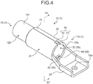
- the female connector 10 and the male connector 110 of the fitting connector 1 are fitted with each other after insertion operation, and accordingly, the male terminal 120 is inserted and fitted in the female terminal 20, and the female terminal 20 and the male terminal 120 are physically and electrically connected ( FIG. 4 ).
- the female connector 10 and the male connector 110 of the fitting connector 1 are disengaged by being separated from each other, whereby the female terminal 20 and the male terminal 120 are physically and electrically disconnected ( FIGS. 1 to 3 ).
- the direction in which a connector is inserted and fitted in the other connector is opposite to the direction in which the connector is disengaged from the other connector.
- the insertion and fitting direction is referred to as a "connector insertion direction” and the disengaging direction is referred to as a “connector disengaging direction”. These directions are used to indicate a direction in which a subject connector is inserted in or separated from the other counterpart connector.
- the female connector 10 includes, in addition to the female terminal 20 and the female-side insulator 30, the female housing 40 ( FIGS. 8 and 9 ) that houses the female terminal 20 and the female-side insulator 30.
- the female terminal 20 is made of a conductive material such as metal.
- the female terminal 20 has a tubular female-side connecting body 21 defining a female-side space 21a ( FIGS. 3 , 8 , and 9 ).
- the female terminal 20 also has a tubular accommodating portion 22 ( FIGS. 5 , 8 , and 9 ) defining an accommodation space 22a in which the female-side insulator 30 is accommodated and retained.
- the female-side connecting body 21 and the accommodating portion 22 of the female terminal 20 are aligned coaxially.
- the female-side connecting body 21 and the accommodating portion 22 are coaxially aligned next to each other.
- the female-side connecting body 21 and the accommodating portion 22 in the present example have a cylindrical shape.
- the female terminal 20 further includes a fastening member 23 ( FIGS. 1 to 6 , 8 , and 9 ) projecting from the accommodating portion 22 in a direction away from the female-side connecting body 21.
- the fastening member 23 is a member for use in fastening the female terminal 20 to a conductive member (not illustrated) to which current flows.
- the fastening member 23 has a through-hole 23a. The fastening member 23 is fastened by screwing to the conductive member with a male screw (not illustrated) inserted in the through-hole 23a.
- a male-side connecting body 121 which will be described later, of the male terminal 120 is coaxially inserted and fitted.
- the female terminal 20 and the male terminal 120 are physically and electrically connected via the female-side connecting body 21 and the male-side connecting body 121 in an inserted and fitted state.
- a contact member 50 ( FIGS. 3 , 5 , and 6 ) is interposed between the female-side connecting body 21 and the male-side connecting body 121, and the female-side connecting body 21 and the male-side connecting body 121 are physically and electrically connected via the contact member 50.
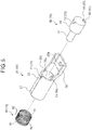
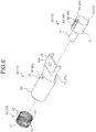
- the contact member 50 includes two ring portions 51 that are coaxially spaced apart and a plurality of contact portions 52 each connecting the two ring portions 51 ( FIGS. 5 and 6 ).
- the contact member 50 is physically and electrically connected to the female-side connecting body 21 with the two ring portions 51 being in contact with and retained by the inner circumferential surface of the female-side connecting body 21 defining the female-side space 21a.
- the ring portions 51 in the present example have an annular shape.
- the contact portions 52 are disposed around the axis.
- the contact portions 52 have elasticity like springs. When the male-side connecting body 121 is inserted, and presses the contact portions 52, the contact portions 52 exert an opposing elastic force. With the elasticity of the contact portions 52, the contact member 50 is physically and electrically connected to the male-side connecting body 121.
- the female-side insulator 30 is made of an insulating material such as synthetic resin.
- the female-side insulator 30 is accommodated in the female-side space 21a and the accommodation space 22a inside the female terminal 20.
- the female-side insulator 30 has a columnar or tubular finger-touching preventing portion 31 ( FIGS. 3 , 5 , 6 , 8 , and 9 ) disposed coaxially in the female-side space 21a.
- the female-side insulator 30 has a columnar or tubular accommodated portion 32 ( FIGS. 1 , 4 to 6 , 8 , and 9 ) accommodated coaxially in the accommodation space 22a.
- the finger-touching preventing portion 31 and the accommodated portion 32 have a columnar shape.
- the finger-touching preventing portion 31 has an outer diameter smaller than the diameter of the female-side space 21a. This configuration creates a tubular space between the finger-touching preventing portion 31 and the inner circumferential surface of the female-side connecting body 21 defining the female-side space 21a.
- the male-side connecting body 121 is inserted in this tubular space.
- the finger-touching preventing portion 31 is disposed in a male-side space 121a, which will be described later, in the male-side connecting body 121 when the female-side connecting body 21 and the male-side connecting body 121 are in an inserted and fitted state.
- the finger-touching preventing portion 31 in the present example is disposed in a first space 131b defined by an outer tube 131, which will be described later, and in the male-side space 121a when the female-side connecting body 21 and the male-side connecting body 121 are in an inserted and fitted state.
- a first space 131b defined by an outer tube 131, which will be described later
- the male-side space 121a when the female-side connecting body 21 and the male-side connecting body 121 are in an inserted and fitted state.
- an end of the finger-touching preventing portion 31 at a side of the connector insertion direction enters in the first space 131b and then reaches the male-side space 121a.
- the finger-touching preventing portion 31 has a ring-shaped chamfered portion 31a ( FIGS.
- the chamfered portion 31a may be a curved surface or a flat surface.
- the chamfered portion 31a in the present example has a tapered shape.
- the female-side insulator 30 is formed separately from the female terminal 20, and is assembled with the female terminal 20 such that the finger-touching preventing portion 31 is inserted in the female-side space 21a in the female-side connecting body 21 and the accommodated portion 32 is inserted in the accommodation space 22a in the accommodating portion 22.
- the accommodated portion 32 is fitted in the accommodation space 22a.
- the female-side insulator 30 is inserted in the female terminal 20 from a side close to the accommodating portion 22.
- the accommodating portion 22 has an opening away from the female-side connecting body 21 for use as an insertion opening 22b ( FIGS. 1 , 4 , 5 , 8 , and 9 ) for the female-side insulator 30.
- the finger-touching preventing portion 31 is first inserted in the insertion opening 22b.
- the female terminal 20 and the female-side insulator 30 of the female connector 10 are assembled such that the female-side insulator 30 is inserted in the female terminal 20 and positioned relative to the female terminal 20 at an expected full accommodation position.
- the expected full accommodation position is a position of the female-side insulator 30 relative to the female terminal 20 at which the female-side insulator 30 can carry out the function (at least a finger-touching preventing function) required for the female-side insulator 30.
- the female connector 10 includes a securing structure 60 ( FIGS. 1 , 2 , 4 to 6 , 8 , and 9 ) between the accommodating portion 22 and the accommodated portion 32 to secure them at the full accommodation position.
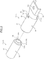
- the securing structure 60 includes a first securing portion 61 included in the accommodating portion 22 and a second securing portion 62 included in the accommodated portion 32 ( FIGS. 2 , 5 , 6 , 8 , and 9 ).
- the securing structure 60 secures the accommodating portion 22 and the accommodated portion 32 at the full accommodation position with the first securing portion 61 and the second securing portion 62 being engaged with each other.
- One of the first securing portion 61 and the second securing portion 62 is formed as a securing protrusion that protrudes in a direction perpendicular to the axis of the accommodating portion 22 and the accommodated portion 32.
- the other one of the first securing portion 61 and the second securing portion 62 is formed as a locking part having a through-hole or indentation shape in which the securing protrusion is inserted to lock the securing protrusion in the axial direction and the circumferential direction of the accommodating portion 22 and the accommodated portion 32.
- the first securing portion 61 is formed as the locking part and the second securing portion 62 is formed as the securing protrusion.
- the second securing portion 62 is provided at a free end of a flexible tip 63 having flexibility ( FIGS. 6 , 8 , and 9 ).
- the flexible tip 63 has a fixed end and the free end that are disposed in the axial direction of the accommodated portion 32.
- the accommodated portion 32 has a retraction space 64 ( FIGS. 1 , 4 to 6 , 8 , and 9 ) into which the second securing portion 62 is retracted when the flexible tip 63 bends radially inward.
- the second securing portion 62 is pushed by the inner circumferential surface of the accommodating portion 22 defining the accommodation space 22a, the flexible tip 63 bends, and accordingly, the second securing portion 62 is retracted into the retraction space 64.
- the flexible tip 63 is released from the bent state and the second securing portion 62 is inserted in the first securing portion 61.
- the female-side insulator 30 is inserted from the insertion opening 22b of the accommodating portion 22 such that the first securing portion 61 is engaged with the second securing portion 62 at the full accommodation position.
- the second securing portion 62 as the securing protrusion is inserted in the first securing portion 61 as the locking part having a through-hole or an indentation shape when the female-side insulator 30 reaches the full accommodation position.
- the separately formed female terminal 20 and female-side insulator 30 can be assembled and positioned relative to each other at the expected full accommodation position.
- This configuration allows the female connector 10 according to the present embodiment to carry out the finger-touching preventing function from the female terminal 20.
- the female connector 10 can carry out a centering function to be described later.
- this securing structure 60 can keep the positional relation between the female terminal 20 and the female-side insulator 30, the female connector 10 can keep the finger-touching preventing function from the female terminal 20 and the centering function even after the connectors are fitted (the male connector 110 is connected to the female connector 10) or after the connectors are disengaged (the male connector 110 is removed from the female connector 10).
- the separately formed female terminal 20 and female-side insulator 30 can be assembled and positioned relative to each other at an expected full accommodation position, this can facilitate the assembling process of the female connector 10.
- This configuration can avoid, for example, mistakenly finishing the assembly of the female terminal 20 and the female-side insulator 30 before the female-side insulator 30 reaches the full accommodation position in assembling the female connector 10.
- This configuration can also prevent over-insertion of the female-side insulator 30 beyond the full accommodation position in the female connector 10.
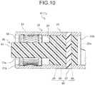
- the securing structure 60 may be configured by the following structures.
- This securing structure 60 is configured by a securing through-hole 65 provided in the accommodating portion 22, a securing space 66 provided in the accommodated portion 32 and facing the securing through-hole 65 at the full accommodation position, and a securing member 67 inserted and fitted in the securing through-hole 65 and the securing space 66 ( FIG. 10 ).
- the accommodating portion 22 has two circular securing through-holes 65 radially disposed and facing each other across the accommodation space 22a.
- the accommodated portion 32 is formed with a columnar through-hole as the securing space 66 with its two openings facing the respective securing through-holes 65.
- the securing member 67 is a columnar pin-like member made of an insulating material such as synthetic resin, and one end of the securing member 67 is inserted in one of the two securing through-holes 65 and is placed in the 66 until the end reaches the other securing through-hole 65.
- the securing member 67 is fitted in the two securing through-holes 65 and the securing space 66. If the female connector 10 includes this type of securing structure 60, it can have the same effect as the previous example above.
- the securing member 67 is made of an insulating material such as synthetic resin
- the securing member 67 may be a columnar pin-like member made of a conductive material such as metal.
- the female connector 10 includes a guide structure 70 ( FIGS. 1 to 6 , 8 , and 9 ) between the accommodating portion 22 and the accommodated portion 32 to guide the accommodated portion 32 inserted from the insertion opening 22b of the accommodating portion 22 in the axial direction to the full accommodation position.
- the guide structure 70 includes a first guide portion 71 provided in the accommodating portion 22 and a second guide portion 72 provided in the accommodated portion 32 ( FIGS. 1 , 3 to 6 , 8 , and 9 ).
- one of the first guide portion 71 and the second guide portion 72 is formed as a guiding protrusion that protrudes in a direction perpendicular to the axis of the accommodating portion 22 and the accommodated portion 32.
- the other one of the first guide portion 71 and the second guide portion 72 is formed as a guiding groove for guiding the guiding protrusion to the full accommodation position when the accommodated portion 32 is inserted from the insertion opening 22b in the axial direction.
- the first guide portion 71 is formed as the guiding groove and the second guide portion 72 is formed as the guiding protrusion.
- a rectangular plate is bent to create a cylindrical shape, thereby forming the female-side connecting body 21 and the accommodating portion 22. First, two edge portions of the rectangular plate in an area corresponding to the accommodating portion 22 after bending are cut out, and then the plate is bent to have the two rectangular cut-out portions meet in the circumferential direction.
- the first guide portion 71 in the present example is configured by the two rectangular cut-out portions disposed next to each other.
- the female-side insulator 30 in the female connector 10 is inserted from the insertion opening 22b of the accommodating portion 22 such that the first guide portion 71 is engaged with the second guide portion 72, that is, the second guide portion 72 formed as the guiding protrusion is inserted in the first guide portion 71 formed as the guiding groove.
- the securing structure 60 is of any type, this configuration facilitates assembling and positioning of the separately formed female terminal 20 and female-side insulator 30 of the female connector 10 relative to each other at an expected full accommodation position.
- the female connector 10 having such configuration can be assembled with much easier assembling process of the female terminal 20 and the female-side insulator 30.
- the female connector 10 has an insulating ring portion 42 ( FIGS. 8 and 9 ) disposed outside of the female-side space 21a in a direction perpendicular to the axial direction of the female-side connecting body 21, and coaxially protruding beyond an end surface 21b of the female-side connecting body 21 at the side of the connector insertion direction. If the inner diameter of the ring portion 42 of the female connector 10 is smaller than the size of a reference finger, the finger-touching preventing function from the female terminal 20 may be carried out by the ring portion 42.
- the reference finger is, for example, the test finger specified in IPXXB degrees of protection.
- the female connector 10 assigns the function of preventing fingers from touching the female terminal 20 to both finger-touching preventing portion 31 and ring portion 42 in a case where the female connector 10 has a larger diameter and thus the ring portion 42 cannot prevent the finger from touching the female terminal 20.
- the finger-touching preventing portion 31 protrudes in the axial direction beyond the end surface 21b of the female-side connecting body 21 at the side of the connector insertion direction ( FIGS. 8 and 9 ). Specifically, an end of the finger-touching preventing portion 31 at the side of the connector insertion direction protrudes beyond the end surface 21b.
- the female connector 10 can prevent fingers from touching the female terminal 20 if the female connector 10 has, for example, a larger diameter to correspond to a larger-current device configuration. In this case, a gap S1 ( FIG.
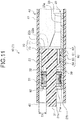
- the outer diameter of the finger-touching preventing portion 31 is determined such that the female connector 10 has such a gap S1, for example. If an increase in the outer diameter of the finger-touching preventing portion 31 is limited, the end of the finger-touching preventing portion 31 may, as illustrated in FIG. 11 , further protrude so that the finger-touching preventing portion 31 and the ring portion 42 can prevent fingers from reaching the female terminal 20. In this case, the ring portion 42 also protrudes further beyond the end surface 21b. For example, the ring portion 42 further protrudes by the same amount as the end of the finger-touching preventing portion 31 protrudes.
- the end of the finger-touching preventing portion 31 at the side of the connector insertion direction protrudes beyond the end surface 21b of the female-side connecting body 21.
- This configuration allows, when the male connector 110 is inserted and fitted in the female connector 10, the end of the finger-touching preventing portion 31 to be inserted in the first space 131b defined by the outer tube 131 of the male-side insulator 130 before the male terminal 120 is inserted and fitted in the female terminal 20.
- the protruding finger-touching preventing portion 31 of the female connector 10 carries out the centering function in inserting and fitting the male connector 110 in the female connector 10.
- the end of the finger-touching preventing portion 31 may protrude beyond the ring portion 42 in the axial direction so that the finger-touching preventing portion 31 is inserted in the outer tube 131 before other portions are inserted in corresponding portions.
- the finger-touching preventing portion 31 may be inserted in the outer tube 131 substantially simultaneously with the insertion operation of a female-side fitting portion 41 and a male-side fitting portion 141, which will be described later.
- the ring portion 42 in the present example is included in the female-side fitting portion 41, which will be described later, of the female housing 40.
- the female housing 40 is made of an insulating material such as synthetic resin.
- the female housing 40 has the female-side fitting portion 41 ( FIGS. 8 and 9 ) having a tubular shape covering the female terminal 20 from outside to accommodate the female terminal 20 therein.
- the female-side fitting portion 41 is coaxially inserted and fitted in the male-side fitting portion 141, which will be described later, of the male housing 140.
- the annular end of the female-side fitting portion 41 at the side of the connector insertion direction, or an end portion at the side of the connector insertion direction, is used as the ring portion 42.
- the end of the female-side fitting portion 41 protrudes in the axial direction beyond the end surface 21b of the female-side connecting body 21 at the side of the connector insertion direction.
- the male connector 110 includes, in addition to the male terminal 120 and the male-side insulator 130, the male housing 140 ( FIGS. 8 and 9 ) that houses the male terminal 120 and the male-side insulator 130.
- the male terminal 120 is made of a conductive material such as metal.
- the male terminal 120 has the tubular male-side connecting body 121 ( FIGS. 1 to 4 and 7 to 9 ) configured to be coaxially inserted and fitted in the female-side space 21a defined by the female-side connecting body 21.
- the male-side connecting body 121 defines the male-side space 121a.
- the male-side connecting body 121 has a cylindrical shape.
- the male-side insulator 130 is made of an insulating material such as synthetic resin.
- the male-side insulator 130 is provided to prevent fingers from touching the end of the male terminal 120 at the side of the connector insertion direction.
- the male-side insulator 130 prevents, together with the male housing 140, fingers from touching the male terminal 120.
- the male-side insulator 130 has the tubular outer tube 131 ( FIGS. 1 , 2 , and 7 to 9 ) that covers coaxially an annular end surface 121b of the male-side connecting body 121 at the side of the connector insertion direction.
- the outer tube 131 has a cylindrical shape.
- the outer tube 131 is inserted in the female-side space 21a of the female-side connecting body 21 together with the male-side connecting body 121.
- the outer tube 131 has substantially the same outer diameter as, for example, that of the male-side connecting body 121 so as not to disturb the insertion operation.
- the outer tube 131 has an annular chamfered portion 131a ( FIGS. 1 , 2 , and 7 ) circumferentially disposed at an end at the side of the connector insertion direction to facilitate insertion of the outer tube 131 in the female-side space 21a.
- the chamfered portion 131a may be a curved surface or a flat surface.
- the chamfered portion 131a in the present example has a tapered shape.
- the finger-touching preventing portion 31 is inserted in the first space 131b ( FIGS. 1 , 2 , and 7 to 9 ) defined by the outer tube 131.
- the first space 131b of the outer tube 131 is formed in such a shape that will not prevent a smooth insertion of the finger-touching preventing portion 31.
- the finger-touching preventing portion 31 is also inserted in the male-side space 121a of the male-side connecting body 121.
- the inner diameter of the male-side connecting body 121 is substantially the same as that of the outer tube 131, and this configuration may cause the finger-touching preventing portion 31 to be in contact with the male-side connecting body 121.
- the fitting connector 1 according to the present embodiment is configured not to allow the finger-touching preventing portion 31 to be in contact with the male-side connecting body 121.
- portions or members of the conventional fitting connector are referred to by the same reference signs as those of the fitting connector 1 according to the present embodiment.
- an insulating tubular inner tube portion 132 ( FIGS. 7 to 9 ) is inserted in the male-side space 121a, and is interposed between the finger-touching preventing portion 31 and the male-side connecting body 121 to prevent them from being in contact with each other.
- the inner tube portion 132 is coaxially inserted in the male-side space 121a.
- the finger-touching preventing portion 31 is inserted in the first space 131b of the outer tube 131 and then in a second space 132a ( FIGS. 8 and 9 ) defined by the inner tube portion 132.
- the inner tube portion 132 has a cylindrical shape.
- the inner tube portion 132 is interposed between the finger-touching preventing portion 31 and the male-side connecting body 121. This configuration can prevent the finger-touching preventing portion 31 from being in contact with the male-side connecting body 121 during inserting or removing of the male terminal 120 in or from the female terminal 20, or while the female terminal 20 and the male terminal 120 are in the inserted and fitted state.
- the finger-touching preventing portion 31, which is relatively softer than the male-side connecting body 121, of the conventional fitting connector touches an edge of the inner circumferential surface of the male-side connecting body 121 close to the outer tube 131 during insertion of the finger-touching preventing portion 31 in the male-side space 121a, the edge may shave the finger-touching preventing portion 31. If the shavings, if any, of the finger-touching preventing portion 31 enter between the female terminal 20 and the male terminal 120 of the conventional fitting connector due to, for example, the vibration during use, this situation may cause failure in electrical connection therebetween.
- the fitting connector 1 according to the present embodiment can prevent creation of such shavings of the finger-touching preventing portion 31 and can increase the service life of the finger-touching preventing portion 31.
- the fitting connector 1 according to the present embodiment can prevent deterioration of electrical connection between the female terminal 20 and the male terminal 120 and thus can keep the connector performance of electrically connecting the male and female connectors.
- the inner tube portion 132 having such a function may be prepared separately from the outer tube 131. However, to reduce the number of parts, which will lead to, for example, an easier assembling work and reduced manufacturing costs, the inner tube portion 132 is integrally formed with the outer tube 131 in one preferred embodiment. In other words, the inner tube portion 132 is provided as part of the male-side insulator 130 in a preferred embodiment. The inner tube portion 132 of the male-side insulator 130 according to the present embodiment coaxially protrudes from the outer tube 131.
- the male-side insulator 130 may be integrally molded (e.g., insert molding) with the male terminal 120 placed in a die.
- the male-side insulator 130 may be formed separately from the male terminal 120 and assembled with the male terminal 120 by inserting the inner tube portion 132 in the male-side space 121a of the male-side connecting body 121.
- the inner tube portion 132 is fitted in the male-side space 121a.
- the axial length of the inner tube portion 132 is such that the end of the finger-touching preventing portion 31 at the side of the connector insertion direction is disposed in the second space 132a when the female-side connecting body 21 and the male-side connecting body 121 are in an inserted and fitted state.
- This configuration of the fitting connector 1 can substantially prevent the vibration of the end of the finger-touching preventing portion 31 if the inner tube portion 132 is a separate part from the male-side insulator 130 or if the inner tube portion 132 is part of the male-side insulator 130, and this can increase the contact prevention effect between the finger-touching preventing portion 31 and the male-side connecting body 121.
- the male connector 110 includes an insulating ring portion 142 ( FIGS. 8 and 9 ) disposed coaxially with the outer tube 131 and outwardly spaced apart from the outer tube 131 in a direction orthogonal to the axial direction of the outer tube 131.
- the male connector 110 includes the outer tube 131 and the ring portion 142 to prevent fingers from touching the male terminal 120.
- the outer tube 131 and the ring portion 142 are spaced apart in the direction orthogonal to their axial direction by a gap S2 ( FIG. 8 ) that is smaller than the size of a reference finger.
- the reference finger is, for example, the test finger specified in IPXXB degrees of protection as described above.
- the ring portion 142 in the present example is included in the male-side fitting portion 141, which will be described later, of the male housing 140.
- the male housing 140 is made of an insulating material such as synthetic resin.
- the male housing 140 has the male-side fitting portion 141 ( FIGS. 8 and 9 ) having a tubular shape covering the male terminal 120 from outside to accommodate the male terminal 120 therein.
- the male connector 110 has a tubular space between the male terminal 120 and the male-side fitting portion 141. In this tubular space, the female-side connecting body 21 of the female terminal 20 and the female-side fitting portion 41 of the female housing 40 are coaxially inserted.
- the annular end of the male-side fitting portion 141 at the side of the connector insertion direction, or an end portion at the side of the connector insertion direction, is used as the ring portion 142.
- the end of the male-side fitting portion 141 protrudes in the axial direction beyond the end surface 121b of the male-side connecting body 121 at the side of the connector insertion direction.
- the fitting connector 1 can prevent fingers from touching the female terminal 20 and the male terminal 120.
- the female connector 10 according to the present embodiment can prevent fingers from touching the female terminal 20 with the ring portion 42 and the finger-touching preventing portion 31 protruding beyond the end surface 21b of the female-side connecting body 21 if the female connector 10 is of any size in the radial direction. Since the female connector 10 according to the present embodiment has the securing structure 60 between the accommodating portion 22 of the female terminal 20 and the accommodated portion 32 of the female-side insulator 30, the female terminal 20 and the female-side insulator 30 can be assembled and positioned relative to each other at an expected full accommodation position, if the female terminal 20 and the female-side insulator 30 are separately formed. This configuration allows the female connector 10 to carry out the finger-touching preventing function from the female connector 20.
- the fitting connector 1 which has a finger-touching preventing function of preventing fingers from touching the female terminal 20 or the male terminal 120, also has a contact preventing function. This function is carried out by the inner tube portion 132 that prevents the finger-touching preventing portion 31 from being in contact with the male-side connecting body 121. This function can substantially prevent deterioration of the electric connection between the female terminal 20 and the male terminal 120.
- the female connector 10 according to the present embodiment which has the finger-touching preventing function from the female terminal 20, can also have a centering function.
- This function is carried out by the finger-touching preventing portion 31 in inserting and fitting of the male connector 110 in the female connector 10.
- the finger-touching preventing portion 31 in the female connector 10 can carry out the finger-touching preventing function from the female terminal 20 and also carry out the centering function in fitting the connectors.
- This centering function is more effective when the end of the finger-touching preventing portion 31 protrudes beyond the end surface 21b of the female-side connecting body 21.
- the centering function is more effective with the effect of the securing function of the securing structure 60. Since the fitting connector 1 according to the present embodiment includes the female connector 10 described above, the fitting connector 1 can have the same effects as those of the female connector 10.
- the female terminal 20 and the female-side insulator 30 of the female connector 10 are separately formed, providing the securing structure 60 between the accommodating portion 22 of the female terminal 20 and the accommodated portion 32 of the female-side insulator 30 can facilitate the assembling process of the female terminal 20 and the female-side insulator 30. Since the fitting connector 1 according to the present embodiment includes the female connector 10 described above, the fitting connector 1 can have the same effects as those of the female connector 10.
- the female connector according to the present embodiment includes a securing structure between the accommodating portion of the female terminal and the accommodated portion of the female-side insulator, and this configuration allows the separately formed female terminal and female-side insulator to be assembled and positioned relative to each other at an expected full accommodation position. Since the fitting connector according to the present invention includes this female connector, the fitting connector can have the same effect as that of the female connector.
Landscapes
- Connector Housings Or Holding Contact Members (AREA)
- Details Of Connecting Devices For Male And Female Coupling (AREA)
Claims (2)
- Passverbinder (1), umfassend eine Buchse (10) und einen Stecker (110), wobei die Buchse (10) umfasst:einen Buchsen-Anschluss (20), der so ausgeführt ist, dass er physisch und elektrisch mit einem Stecker-Anschluss (120) des Steckers (110) verbunden wird, der den Stecker-Anschluss (120) und einen isolierenden steckerseitigen Isolator (130) enthält, wobei der Stecker-Anschluss (120) einen röhrenförmigen steckerseitigen Verbindungskörper (121) aufweist, der steckerseitige Isolator (130) eine röhrenförmige äußere Hülse (131) aufweist, die eine Endfläche (121b) des steckerseitigen Verbindungskörpers (121) an einer Seite einer Verbinder-Einführungsrichtung koaxial abdeckt; sowieeinen isolierenden buchsenseitigen Isolator (30), wobeider Buchsen-Anschluss (20) einen röhrenförmigen buchsenseitigen Verbindungskörper (21) aufweist, der einen buchsenseitigen Raum (21a) bildet, in den der steckerseitige Verbindungskörper (121) koaxial eingesetzt und eingepasst wird, sowie einen röhrenförmigen aufnehmenden Abschnitt (22) aufweist, der einen Aufnahmeraum bildet, in dem der buchsenseitige Isolator (30) aufgenommen und gehalten wird, wobei der buchsenseitige Verbindungskörper (21) und der aufnehmende Abschnitt (22) koaxial ausgerichtet sind,der buchsenseitige Isolator (30) einen säulenförmigen oder röhrenförmigen Abschnitt (31) zur Verhinderung von Fingerberührung sowie einen säulenförmigen oder röhrenförmigen aufgenommenen Abschnitt (32) aufweist, wobei der Abschnitt (31) zur Verhinderung von Fingerberührung koaxial in dem buchsenseitigen Raum (21a) angeordnet ist, und in einem durch die äußere Hülse (131) gebildeten Raum sowie in einem durch den steckerseitigen Verbindungskörper (121) gebildeten steckerseitigen Raum (121a) angeordnet ist, wenn sich der buchsenseitige Verbindungskörper (21) und der steckerseitige Verbindungskörper (121) in einem eingeführten und eingepassten Zustand befinden, wobei der aufgenommene Abschnitt (32) koaxial in dem Aufnahmeraum (22a) aufgenommen ist, undeine Sicherungsstruktur (60), die den aufnehmenden Abschnitt (22) und den aufgenommenen Abschnitt (32) relativ zueinander in einer vollständigen Aufnahmeposition sichert, zwischen dem aufnehmenden Abschnitt (22) und dem aufgenommenen Abschnitt (32) vorhanden ist,die Sicherungsstruktur (60) einen ersten Sicherungsabschnitt (61), der in dem aufnehmenden Abschnitt (22) vorhanden ist, sowie einen zweiten Sicherungsabschnitt (62) einschließt, der in dem aufgenommenen Abschnitt (32) vorhanden ist, wobei der erste Sicherungsabschnitt (61) und der zweite Sicherungsabschnitt (62) miteinander in Eingriff sind, um den aufnehmenden Abschnitt (22) und den aufgenommenen Abschnitt (32) relativ zueinander in der vollständigen Aufnahmeposition zu sichern,
der zweite Sicherungsabschnitt (62) als ein Sicherungsvorsprung ausgebildet ist, der in einer Richtung im rechten Winkel zu einer axialen Richtung des aufnehmenden Abschnitts (22) vorsteht,
dadurch gekennzeichnet, dass der erste Sicherungsabschnitt (61) als ein Arretierteil mit einem Durchgangsloch oder einer Vertiefungsform ausgebildet ist, und in den Arretierteil der Sicherungsvorsprung in der axialen Richtung und einer Umfangsrichtung des aufnehmenden Abschnitts (22) und des aufgenommenen Abschnitts (32) eingeführt und arretiert wird,
der aufgenommene Abschnitt (32) einen Einzugsraum (64) und eine biegsame Spitze (63) hat, die Flexibilität aufweist,
die biegsame Spitze (63) ein festes und ein freies Ende hat,
der Sicherungsvorsprung an dem freien Ende vorhanden ist, und
der Sicherungsvorsprung so ausgeführt ist, dass er unter Biegen der biegsamen Spitze (63) in den Einzugsraum (64) eingezogen wird und dabei durch die Innenumfangsfläche des Aufnahmeraums (22a) geschoben wird, und die biegsame Spitze (63) so ausgeführt ist, dass sie in den Einzugsraum (64) bewegt wird, und der erste Sicherungsabschnitt (61) so ausgeführt ist, dass er mit dem zweiten Sicherungsabschnitt (62) in Eingriff gebracht wird, indem er zusammen mit der Aufhebung des gebogenen Zustandes der biegsamen Spitze (63) in den Arretierteil eingeführt wird. - Passverbinder (1) nach Anspruch 1, wobei
der aufnehmende Abschnitt (22) eine von dem buchsenseitigen Verbindungskörper (21) entfernte Öffnung aufweist, wobei die Öffnung als Einführungsöffnung (22b) für den buchsenseitigen Isolator (30) dient, und
die Buchse (10) des Weiteren eine Führungsstruktur (70) zwischen dem aufnehmenden Abschnitt (22) und dem aufgenommenen Abschnitt (32) enthält, die den aufgenommenen Abschnitt (32), der über die Einführungsöffnung (22b) axial eingeführt wird, führt, bis die vollständige Aufnahmeposition erreicht ist.
Applications Claiming Priority (1)
| Application Number | Priority Date | Filing Date | Title |
|---|---|---|---|
| JP2018092789A JP6753891B2 (ja) | 2018-05-14 | 2018-05-14 | 雌コネクタ及び嵌合コネクタ |
Publications (2)
| Publication Number | Publication Date |
|---|---|
| EP3570382A1 EP3570382A1 (de) | 2019-11-20 |
| EP3570382B1 true EP3570382B1 (de) | 2020-10-07 |
Family
ID=66102463
Family Applications (1)
| Application Number | Title | Priority Date | Filing Date |
|---|---|---|---|
| EP19167766.5A Active EP3570382B1 (de) | 2018-05-14 | 2019-04-08 | Passender steckverbinder |
Country Status (4)
| Country | Link |
|---|---|
| US (1) | US10804623B2 (de) |
| EP (1) | EP3570382B1 (de) |
| JP (1) | JP6753891B2 (de) |
| CN (1) | CN110492277B (de) |
Families Citing this family (7)
| Publication number | Priority date | Publication date | Assignee | Title |
|---|---|---|---|---|
| JP6724857B2 (ja) * | 2017-05-11 | 2020-07-15 | 住友電装株式会社 | コネクタ |
| DE102020112117A1 (de) * | 2020-05-05 | 2021-11-11 | Te Connectivity Germany Gmbh | Steckverbinder, Steckverbindergegenstück und Steckverbindersystem |
| DE102021115707A1 (de) * | 2021-06-17 | 2022-12-22 | Amphenol Tuchel Industrial GmbH | Berührschutzpin |
| EP4262026A1 (de) * | 2022-04-12 | 2023-10-18 | Yazaki Europe Ltd. | Elektrische verbinderanordnung, hochspannungsanschluss und verfahren zum zusammenbau |
| CN119895674A (zh) * | 2022-09-15 | 2025-04-25 | 史陶比尔电子连接器股份公司 | 电连接器组件 |
| DE102023100531A1 (de) * | 2023-01-11 | 2024-07-11 | Amphenol Tuchel Industrial GmbH | Kontaktanordnung mit Busbar-Kontaktanschluss |
| CN219760012U (zh) * | 2023-05-16 | 2023-09-26 | 泰科电子(上海)有限公司 | 端子组件和连接器 |
Family Cites Families (19)
| Publication number | Priority date | Publication date | Assignee | Title |
|---|---|---|---|---|
| US4152041A (en) * | 1978-02-17 | 1979-05-01 | Amp Incorporated | Hybrid filter header |
| JPH07296879A (ja) * | 1994-04-26 | 1995-11-10 | Amp Japan Ltd | 電気コネクタ |
| JPH0878079A (ja) | 1994-09-01 | 1996-03-22 | Japan Aviation Electron Ind Ltd | コネクタ及びソケットコンタクト |
| JP3271178B2 (ja) * | 1995-03-03 | 2002-04-02 | 矢崎総業株式会社 | 金属シールドの接続構造 |
| US5588852A (en) * | 1995-03-21 | 1996-12-31 | The Whitaker Corporation | Electrical connector having socket contacts with safety shields |
| JP3575295B2 (ja) * | 1998-04-15 | 2004-10-13 | 住友電装株式会社 | 電気接続用コネクタのプラグ |
| JP3670495B2 (ja) * | 1998-11-09 | 2005-07-13 | 矢崎総業株式会社 | 端子 |
| JP2002042989A (ja) * | 2000-07-21 | 2002-02-08 | Sumitomo Wiring Syst Ltd | シールド端子 |
| JP2006040838A (ja) * | 2004-07-30 | 2006-02-09 | Yazaki Corp | 雌雄コネクタの嵌合構造 |
| US8403702B2 (en) * | 2011-06-22 | 2013-03-26 | Tyco Electronics Brasil Ltda. | Releasable electrical connector adaptor and assembly |
| JP5757198B2 (ja) * | 2011-08-29 | 2015-07-29 | 住友電装株式会社 | コネクタ |
| JP5973865B2 (ja) * | 2012-10-10 | 2016-08-23 | 矢崎総業株式会社 | 触指防止コネクタ |
| DE102013209690B4 (de) * | 2013-05-24 | 2023-08-03 | Te Connectivity Germany Gmbh | HV-Fingerschutz |
| JP6185900B2 (ja) * | 2014-11-04 | 2017-08-23 | 矢崎総業株式会社 | コネクタ |
| FR3048136B1 (fr) | 2016-02-18 | 2021-05-14 | Ilie Razvan | Connecteur electrique comportant une pluralite de lamelles electriquement conductrices |
| JP6349345B2 (ja) * | 2016-05-20 | 2018-06-27 | 矢崎総業株式会社 | プラグコネクタ及び電源回路遮断装置 |
| CN109643873A (zh) * | 2016-06-24 | 2019-04-16 | 莫列斯有限公司 | 具有端子的电源连接器 |
| JP2019200844A (ja) * | 2018-05-14 | 2019-11-21 | 矢崎総業株式会社 | 雌コネクタ及び嵌合コネクタ |
| JP6807346B2 (ja) * | 2018-05-14 | 2021-01-06 | 矢崎総業株式会社 | 嵌合コネクタ |
-
2018
- 2018-05-14 JP JP2018092789A patent/JP6753891B2/ja active Active
-
2019
- 2019-04-08 EP EP19167766.5A patent/EP3570382B1/de active Active
- 2019-04-30 US US16/400,005 patent/US10804623B2/en active Active
- 2019-05-13 CN CN201910400233.3A patent/CN110492277B/zh not_active Expired - Fee Related
Non-Patent Citations (1)
| Title |
|---|
| None * |
Also Published As
| Publication number | Publication date |
|---|---|
| US20190348774A1 (en) | 2019-11-14 |
| CN110492277A (zh) | 2019-11-22 |
| JP6753891B2 (ja) | 2020-09-09 |
| US10804623B2 (en) | 2020-10-13 |
| CN110492277B (zh) | 2021-01-08 |
| JP2019200842A (ja) | 2019-11-21 |
| EP3570382A1 (de) | 2019-11-20 |
Similar Documents
| Publication | Publication Date | Title |
|---|---|---|
| US10804623B2 (en) | Female connector and fitting connector | |
| EP2415128B1 (de) | Koaxialverbinder mit innerer abschirmanordnung und verfahren zum zusammenbau eines solchen | |
| US10553996B2 (en) | Female connector and fitting connector | |
| US11646522B2 (en) | Male connector and connector device | |
| EP3570380B1 (de) | Passender steckverbinder | |
| EP2719024B1 (de) | Steckverbinder | |
| CN110518390B (zh) | 封闭体保持结构和带连接器的电线 | |
| US10819059B2 (en) | Connector | |
| CN108808314B (zh) | 气囊点火机构的电连接器组件 | |
| WO2010119011A1 (en) | Coaxial connector and method of assembling one | |
| CN111937253B (zh) | 连接器 | |
| CN104124556A (zh) | 具有弹性锁闩的电连接器 | |
| US12374835B2 (en) | Connectors and connector assembly | |
| EP3467957B1 (de) | Verbindungsteil, verfahren zur verbindung eines ersten verbingungsteils mit einem zweiten verbindungsteils und verfahren zur entkopplung eines ersten verbindungsteils von einem zweiten verbindungsteil | |
| US20180034183A1 (en) | Electrical connector with integrated anti-decoupling features | |
| CN115995724B (zh) | 连接器 | |
| US8079868B2 (en) | Electrical connector with releasable locking clip | |
| JP2025086357A (ja) | コネクタコアアセンブリ、コネクタおよびコネクタアセンブリ | |
| CN116914499A (zh) | 插头及连接器 | |
| JP2025125237A (ja) | コネクタおよび端子ユニット | |
| EP3629427A1 (de) | Trennbare hochspannungsverbinderbaugruppe und herstellungsverfahren dafür | |
| CN113437566A (zh) | 连接器及包括其的连接器组件 | |
| JP2016134223A (ja) | コネクタ、及び、ワイヤハーネス |
Legal Events
| Date | Code | Title | Description |
|---|---|---|---|
| PUAI | Public reference made under article 153(3) epc to a published international application that has entered the european phase |
Free format text: ORIGINAL CODE: 0009012 |
|
| STAA | Information on the status of an ep patent application or granted ep patent |
Free format text: STATUS: REQUEST FOR EXAMINATION WAS MADE |
|
| 17P | Request for examination filed |
Effective date: 20190408 |
|
| AK | Designated contracting states |
Kind code of ref document: A1 Designated state(s): AL AT BE BG CH CY CZ DE DK EE ES FI FR GB GR HR HU IE IS IT LI LT LU LV MC MK MT NL NO PL PT RO RS SE SI SK SM TR |
|
| AX | Request for extension of the european patent |
Extension state: BA ME |
|
| RBV | Designated contracting states (corrected) |
Designated state(s): AL AT BE BG CH CY CZ DE DK EE ES FI FR GB GR HR HU IE IS IT LI LT LU LV MC MK MT NL NO PL PT RO RS SE SI SK SM TR |
|
| GRAP | Despatch of communication of intention to grant a patent |
Free format text: ORIGINAL CODE: EPIDOSNIGR1 |
|
| STAA | Information on the status of an ep patent application or granted ep patent |
Free format text: STATUS: GRANT OF PATENT IS INTENDED |
|
| RIC1 | Information provided on ipc code assigned before grant |
Ipc: H01R 11/28 20060101ALN20200622BHEP Ipc: H01R 13/187 20060101ALN20200622BHEP Ipc: H01R 13/04 20060101ALN20200622BHEP Ipc: H01R 13/44 20060101AFI20200622BHEP |
|
| RIC1 | Information provided on ipc code assigned before grant |
Ipc: H01R 13/187 20060101ALN20200702BHEP Ipc: H01R 13/04 20060101ALN20200702BHEP Ipc: H01R 11/28 20060101ALN20200702BHEP Ipc: H01R 13/44 20060101AFI20200702BHEP |
|
| INTG | Intention to grant announced |
Effective date: 20200717 |
|
| GRAS | Grant fee paid |
Free format text: ORIGINAL CODE: EPIDOSNIGR3 |
|
| GRAA | (expected) grant |
Free format text: ORIGINAL CODE: 0009210 |
|
| STAA | Information on the status of an ep patent application or granted ep patent |
Free format text: STATUS: THE PATENT HAS BEEN GRANTED |
|
| AK | Designated contracting states |
Kind code of ref document: B1 Designated state(s): AL AT BE BG CH CY CZ DE DK EE ES FI FR GB GR HR HU IE IS IT LI LT LU LV MC MK MT NL NO PL PT RO RS SE SI SK SM TR |
|
| REG | Reference to a national code |
Ref country code: GB Ref legal event code: FG4D |
|
| REG | Reference to a national code |
Ref country code: CH Ref legal event code: EP Ref country code: AT Ref legal event code: REF Ref document number: 1322158 Country of ref document: AT Kind code of ref document: T Effective date: 20201015 |
|
| REG | Reference to a national code |
Ref country code: IE Ref legal event code: FG4D |
|
| REG | Reference to a national code |
Ref country code: DE Ref legal event code: R096 Ref document number: 602019000870 Country of ref document: DE |
|
| REG | Reference to a national code |
Ref country code: NL Ref legal event code: MP Effective date: 20201007 |
|
| REG | Reference to a national code |
Ref country code: AT Ref legal event code: MK05 Ref document number: 1322158 Country of ref document: AT Kind code of ref document: T Effective date: 20201007 |
|
| PG25 | Lapsed in a contracting state [announced via postgrant information from national office to epo] |
Ref country code: NO Free format text: LAPSE BECAUSE OF FAILURE TO SUBMIT A TRANSLATION OF THE DESCRIPTION OR TO PAY THE FEE WITHIN THE PRESCRIBED TIME-LIMIT Effective date: 20210107 Ref country code: GR Free format text: LAPSE BECAUSE OF FAILURE TO SUBMIT A TRANSLATION OF THE DESCRIPTION OR TO PAY THE FEE WITHIN THE PRESCRIBED TIME-LIMIT Effective date: 20210108 Ref country code: PT Free format text: LAPSE BECAUSE OF FAILURE TO SUBMIT A TRANSLATION OF THE DESCRIPTION OR TO PAY THE FEE WITHIN THE PRESCRIBED TIME-LIMIT Effective date: 20210208 Ref country code: RS Free format text: LAPSE BECAUSE OF FAILURE TO SUBMIT A TRANSLATION OF THE DESCRIPTION OR TO PAY THE FEE WITHIN THE PRESCRIBED TIME-LIMIT Effective date: 20201007 Ref country code: FI Free format text: LAPSE BECAUSE OF FAILURE TO SUBMIT A TRANSLATION OF THE DESCRIPTION OR TO PAY THE FEE WITHIN THE PRESCRIBED TIME-LIMIT Effective date: 20201007 |
|
| REG | Reference to a national code |
Ref country code: LT Ref legal event code: MG4D |
|
| PG25 | Lapsed in a contracting state [announced via postgrant information from national office to epo] |
Ref country code: PL Free format text: LAPSE BECAUSE OF FAILURE TO SUBMIT A TRANSLATION OF THE DESCRIPTION OR TO PAY THE FEE WITHIN THE PRESCRIBED TIME-LIMIT Effective date: 20201007 Ref country code: IS Free format text: LAPSE BECAUSE OF FAILURE TO SUBMIT A TRANSLATION OF THE DESCRIPTION OR TO PAY THE FEE WITHIN THE PRESCRIBED TIME-LIMIT Effective date: 20210207 Ref country code: LV Free format text: LAPSE BECAUSE OF FAILURE TO SUBMIT A TRANSLATION OF THE DESCRIPTION OR TO PAY THE FEE WITHIN THE PRESCRIBED TIME-LIMIT Effective date: 20201007 Ref country code: SE Free format text: LAPSE BECAUSE OF FAILURE TO SUBMIT A TRANSLATION OF THE DESCRIPTION OR TO PAY THE FEE WITHIN THE PRESCRIBED TIME-LIMIT Effective date: 20201007 Ref country code: BG Free format text: LAPSE BECAUSE OF FAILURE TO SUBMIT A TRANSLATION OF THE DESCRIPTION OR TO PAY THE FEE WITHIN THE PRESCRIBED TIME-LIMIT Effective date: 20210107 Ref country code: AT Free format text: LAPSE BECAUSE OF FAILURE TO SUBMIT A TRANSLATION OF THE DESCRIPTION OR TO PAY THE FEE WITHIN THE PRESCRIBED TIME-LIMIT Effective date: 20201007 Ref country code: ES Free format text: LAPSE BECAUSE OF FAILURE TO SUBMIT A TRANSLATION OF THE DESCRIPTION OR TO PAY THE FEE WITHIN THE PRESCRIBED TIME-LIMIT Effective date: 20201007 |
|
| PG25 | Lapsed in a contracting state [announced via postgrant information from national office to epo] |
Ref country code: NL Free format text: LAPSE BECAUSE OF FAILURE TO SUBMIT A TRANSLATION OF THE DESCRIPTION OR TO PAY THE FEE WITHIN THE PRESCRIBED TIME-LIMIT Effective date: 20201007 Ref country code: HR Free format text: LAPSE BECAUSE OF FAILURE TO SUBMIT A TRANSLATION OF THE DESCRIPTION OR TO PAY THE FEE WITHIN THE PRESCRIBED TIME-LIMIT Effective date: 20201007 |
|
| REG | Reference to a national code |
Ref country code: DE Ref legal event code: R097 Ref document number: 602019000870 Country of ref document: DE |
|
| PG25 | Lapsed in a contracting state [announced via postgrant information from national office to epo] |
Ref country code: CZ Free format text: LAPSE BECAUSE OF FAILURE TO SUBMIT A TRANSLATION OF THE DESCRIPTION OR TO PAY THE FEE WITHIN THE PRESCRIBED TIME-LIMIT Effective date: 20201007 Ref country code: EE Free format text: LAPSE BECAUSE OF FAILURE TO SUBMIT A TRANSLATION OF THE DESCRIPTION OR TO PAY THE FEE WITHIN THE PRESCRIBED TIME-LIMIT Effective date: 20201007 Ref country code: SK Free format text: LAPSE BECAUSE OF FAILURE TO SUBMIT A TRANSLATION OF THE DESCRIPTION OR TO PAY THE FEE WITHIN THE PRESCRIBED TIME-LIMIT Effective date: 20201007 Ref country code: SM Free format text: LAPSE BECAUSE OF FAILURE TO SUBMIT A TRANSLATION OF THE DESCRIPTION OR TO PAY THE FEE WITHIN THE PRESCRIBED TIME-LIMIT Effective date: 20201007 Ref country code: LT Free format text: LAPSE BECAUSE OF FAILURE TO SUBMIT A TRANSLATION OF THE DESCRIPTION OR TO PAY THE FEE WITHIN THE PRESCRIBED TIME-LIMIT Effective date: 20201007 Ref country code: RO Free format text: LAPSE BECAUSE OF FAILURE TO SUBMIT A TRANSLATION OF THE DESCRIPTION OR TO PAY THE FEE WITHIN THE PRESCRIBED TIME-LIMIT Effective date: 20201007 |
|
| PLBE | No opposition filed within time limit |
Free format text: ORIGINAL CODE: 0009261 |
|
| STAA | Information on the status of an ep patent application or granted ep patent |
Free format text: STATUS: NO OPPOSITION FILED WITHIN TIME LIMIT |
|
| PG25 | Lapsed in a contracting state [announced via postgrant information from national office to epo] |
Ref country code: DK Free format text: LAPSE BECAUSE OF FAILURE TO SUBMIT A TRANSLATION OF THE DESCRIPTION OR TO PAY THE FEE WITHIN THE PRESCRIBED TIME-LIMIT Effective date: 20201007 |
|
| 26N | No opposition filed |
Effective date: 20210708 |
|
| PG25 | Lapsed in a contracting state [announced via postgrant information from national office to epo] |
Ref country code: AL Free format text: LAPSE BECAUSE OF FAILURE TO SUBMIT A TRANSLATION OF THE DESCRIPTION OR TO PAY THE FEE WITHIN THE PRESCRIBED TIME-LIMIT Effective date: 20201007 Ref country code: IT Free format text: LAPSE BECAUSE OF FAILURE TO SUBMIT A TRANSLATION OF THE DESCRIPTION OR TO PAY THE FEE WITHIN THE PRESCRIBED TIME-LIMIT Effective date: 20201007 |
|
| PG25 | Lapsed in a contracting state [announced via postgrant information from national office to epo] |
Ref country code: MC Free format text: LAPSE BECAUSE OF FAILURE TO SUBMIT A TRANSLATION OF THE DESCRIPTION OR TO PAY THE FEE WITHIN THE PRESCRIBED TIME-LIMIT Effective date: 20201007 Ref country code: SI Free format text: LAPSE BECAUSE OF FAILURE TO SUBMIT A TRANSLATION OF THE DESCRIPTION OR TO PAY THE FEE WITHIN THE PRESCRIBED TIME-LIMIT Effective date: 20201007 |
|
| PG25 | Lapsed in a contracting state [announced via postgrant information from national office to epo] |
Ref country code: LU Free format text: LAPSE BECAUSE OF NON-PAYMENT OF DUE FEES Effective date: 20210408 |
|
| REG | Reference to a national code |
Ref country code: BE Ref legal event code: MM Effective date: 20210430 |
|
| PG25 | Lapsed in a contracting state [announced via postgrant information from national office to epo] |
Ref country code: FR Free format text: LAPSE BECAUSE OF NON-PAYMENT OF DUE FEES Effective date: 20210430 |
|
| PG25 | Lapsed in a contracting state [announced via postgrant information from national office to epo] |
Ref country code: IE Free format text: LAPSE BECAUSE OF NON-PAYMENT OF DUE FEES Effective date: 20210408 |
|
| PG25 | Lapsed in a contracting state [announced via postgrant information from national office to epo] |
Ref country code: IS Free format text: LAPSE BECAUSE OF FAILURE TO SUBMIT A TRANSLATION OF THE DESCRIPTION OR TO PAY THE FEE WITHIN THE PRESCRIBED TIME-LIMIT Effective date: 20210207 |
|
| PG25 | Lapsed in a contracting state [announced via postgrant information from national office to epo] |
Ref country code: BE Free format text: LAPSE BECAUSE OF NON-PAYMENT OF DUE FEES Effective date: 20210430 |
|
| REG | Reference to a national code |
Ref country code: CH Ref legal event code: PL |
|
| PG25 | Lapsed in a contracting state [announced via postgrant information from national office to epo] |
Ref country code: LI Free format text: LAPSE BECAUSE OF NON-PAYMENT OF DUE FEES Effective date: 20220430 Ref country code: CH Free format text: LAPSE BECAUSE OF NON-PAYMENT OF DUE FEES Effective date: 20220430 |
|
| PG25 | Lapsed in a contracting state [announced via postgrant information from national office to epo] |
Ref country code: CY Free format text: LAPSE BECAUSE OF FAILURE TO SUBMIT A TRANSLATION OF THE DESCRIPTION OR TO PAY THE FEE WITHIN THE PRESCRIBED TIME-LIMIT Effective date: 20201007 |
|
| PG25 | Lapsed in a contracting state [announced via postgrant information from national office to epo] |
Ref country code: HU Free format text: LAPSE BECAUSE OF FAILURE TO SUBMIT A TRANSLATION OF THE DESCRIPTION OR TO PAY THE FEE WITHIN THE PRESCRIBED TIME-LIMIT; INVALID AB INITIO Effective date: 20190408 |
|
| GBPC | Gb: european patent ceased through non-payment of renewal fee |
Effective date: 20230408 |
|
| PG25 | Lapsed in a contracting state [announced via postgrant information from national office to epo] |
Ref country code: GB Free format text: LAPSE BECAUSE OF NON-PAYMENT OF DUE FEES Effective date: 20230408 |
|
| PG25 | Lapsed in a contracting state [announced via postgrant information from national office to epo] |
Ref country code: GB Free format text: LAPSE BECAUSE OF NON-PAYMENT OF DUE FEES Effective date: 20230408 |
|
| PG25 | Lapsed in a contracting state [announced via postgrant information from national office to epo] |
Ref country code: MK Free format text: LAPSE BECAUSE OF FAILURE TO SUBMIT A TRANSLATION OF THE DESCRIPTION OR TO PAY THE FEE WITHIN THE PRESCRIBED TIME-LIMIT Effective date: 20201007 |
|
| PG25 | Lapsed in a contracting state [announced via postgrant information from national office to epo] |
Ref country code: MT Free format text: LAPSE BECAUSE OF FAILURE TO SUBMIT A TRANSLATION OF THE DESCRIPTION OR TO PAY THE FEE WITHIN THE PRESCRIBED TIME-LIMIT Effective date: 20201007 |
|
| PGFP | Annual fee paid to national office [announced via postgrant information from national office to epo] |
Ref country code: DE Payment date: 20250305 Year of fee payment: 7 |
|
| PG25 | Lapsed in a contracting state [announced via postgrant information from national office to epo] |
Ref country code: TR Free format text: LAPSE BECAUSE OF FAILURE TO SUBMIT A TRANSLATION OF THE DESCRIPTION OR TO PAY THE FEE WITHIN THE PRESCRIBED TIME-LIMIT Effective date: 20201007 |