EP3569534B1 - Stanzlingsapplikator und verfahren zur applikation eines stanzlings - Google Patents
Stanzlingsapplikator und verfahren zur applikation eines stanzlings Download PDFInfo
- Publication number
- EP3569534B1 EP3569534B1 EP19174000.0A EP19174000A EP3569534B1 EP 3569534 B1 EP3569534 B1 EP 3569534B1 EP 19174000 A EP19174000 A EP 19174000A EP 3569534 B1 EP3569534 B1 EP 3569534B1
- Authority
- EP
- European Patent Office
- Prior art keywords
- die
- strip
- cut
- suction belt
- liner
- Prior art date
- Legal status (The legal status is an assumption and is not a legal conclusion. Google has not performed a legal analysis and makes no representation as to the accuracy of the status listed.)
- Active
Links
Images

Classifications
-
- B—PERFORMING OPERATIONS; TRANSPORTING
- B05—SPRAYING OR ATOMISING IN GENERAL; APPLYING FLUENT MATERIALS TO SURFACES, IN GENERAL
- B05D—PROCESSES FOR APPLYING FLUENT MATERIALS TO SURFACES, IN GENERAL
- B05D7/00—Processes, other than flocking, specially adapted for applying liquids or other fluent materials to particular surfaces or for applying particular liquids or other fluent materials
- B05D7/14—Processes, other than flocking, specially adapted for applying liquids or other fluent materials to particular surfaces or for applying particular liquids or other fluent materials to metal, e.g. car bodies
-
- B—PERFORMING OPERATIONS; TRANSPORTING
- B65—CONVEYING; PACKING; STORING; HANDLING THIN OR FILAMENTARY MATERIAL
- B65H—HANDLING THIN OR FILAMENTARY MATERIAL, e.g. SHEETS, WEBS, CABLES
- B65H37/00—Article or web delivery apparatus incorporating devices for performing specified auxiliary operations
- B65H37/002—Web delivery apparatus, the web serving as support for articles, material or another web
-
- B—PERFORMING OPERATIONS; TRANSPORTING
- B65—CONVEYING; PACKING; STORING; HANDLING THIN OR FILAMENTARY MATERIAL
- B65C—LABELLING OR TAGGING MACHINES, APPARATUS, OR PROCESSES
- B65C1/00—Labelling flat essentially-rigid surfaces
- B65C1/04—Affixing labels, e.g. wrap-around labels, to two or more flat surfaces of a polyhedral article
-
- B—PERFORMING OPERATIONS; TRANSPORTING
- B05—SPRAYING OR ATOMISING IN GENERAL; APPLYING FLUENT MATERIALS TO SURFACES, IN GENERAL
- B05D—PROCESSES FOR APPLYING FLUENT MATERIALS TO SURFACES, IN GENERAL
- B05D1/00—Processes for applying liquids or other fluent materials
- B05D1/28—Processes for applying liquids or other fluent materials performed by transfer from the surfaces of elements carrying the liquid or other fluent material, e.g. brushes, pads, rollers
-
- B—PERFORMING OPERATIONS; TRANSPORTING
- B65—CONVEYING; PACKING; STORING; HANDLING THIN OR FILAMENTARY MATERIAL
- B65C—LABELLING OR TAGGING MACHINES, APPARATUS, OR PROCESSES
- B65C9/00—Details of labelling machines or apparatus
- B65C9/08—Label feeding
- B65C9/18—Label feeding from strips, e.g. from rolls
-
- B—PERFORMING OPERATIONS; TRANSPORTING
- B65—CONVEYING; PACKING; STORING; HANDLING THIN OR FILAMENTARY MATERIAL
- B65C—LABELLING OR TAGGING MACHINES, APPARATUS, OR PROCESSES
- B65C9/00—Details of labelling machines or apparatus
- B65C9/08—Label feeding
- B65C9/18—Label feeding from strips, e.g. from rolls
- B65C9/1803—Label feeding from strips, e.g. from rolls the labels being cut from a strip
- B65C9/1815—Label feeding from strips, e.g. from rolls the labels being cut from a strip and transferred by suction means
- B65C9/1826—Label feeding from strips, e.g. from rolls the labels being cut from a strip and transferred by suction means the suction means being a movable vacuum arm or pad
-
- B—PERFORMING OPERATIONS; TRANSPORTING
- B65—CONVEYING; PACKING; STORING; HANDLING THIN OR FILAMENTARY MATERIAL
- B65C—LABELLING OR TAGGING MACHINES, APPARATUS, OR PROCESSES
- B65C9/00—Details of labelling machines or apparatus
- B65C9/20—Gluing the labels or articles
- B65C9/24—Gluing the labels or articles by heat
- B65C9/25—Gluing the labels or articles by heat by thermo-activating the glue
-
- B—PERFORMING OPERATIONS; TRANSPORTING
- B65—CONVEYING; PACKING; STORING; HANDLING THIN OR FILAMENTARY MATERIAL
- B65C—LABELLING OR TAGGING MACHINES, APPARATUS, OR PROCESSES
- B65C9/00—Details of labelling machines or apparatus
- B65C9/26—Devices for applying labels
- B65C9/30—Rollers
-
- B—PERFORMING OPERATIONS; TRANSPORTING
- B65—CONVEYING; PACKING; STORING; HANDLING THIN OR FILAMENTARY MATERIAL
- B65C—LABELLING OR TAGGING MACHINES, APPARATUS, OR PROCESSES
- B65C9/00—Details of labelling machines or apparatus
- B65C9/40—Controls; Safety devices
- B65C9/42—Label feed control
-
- B—PERFORMING OPERATIONS; TRANSPORTING
- B65—CONVEYING; PACKING; STORING; HANDLING THIN OR FILAMENTARY MATERIAL
- B65H—HANDLING THIN OR FILAMENTARY MATERIAL, e.g. SHEETS, WEBS, CABLES
- B65H2301/00—Handling processes for sheets or webs
- B65H2301/50—Auxiliary process performed during handling process
- B65H2301/51—Modifying a characteristic of handled material
- B65H2301/511—Processing surface of handled material upon transport or guiding thereof, e.g. cleaning
- B65H2301/5112—Processing surface of handled material upon transport or guiding thereof, e.g. cleaning removing material from outer surface
- B65H2301/51122—Processing surface of handled material upon transport or guiding thereof, e.g. cleaning removing material from outer surface peeling layer of material
-
- B—PERFORMING OPERATIONS; TRANSPORTING
- B65—CONVEYING; PACKING; STORING; HANDLING THIN OR FILAMENTARY MATERIAL
- B65H—HANDLING THIN OR FILAMENTARY MATERIAL, e.g. SHEETS, WEBS, CABLES
- B65H2406/00—Means using fluid
- B65H2406/30—Suction means
- B65H2406/32—Suction belts
-
- B—PERFORMING OPERATIONS; TRANSPORTING
- B65—CONVEYING; PACKING; STORING; HANDLING THIN OR FILAMENTARY MATERIAL
- B65H—HANDLING THIN OR FILAMENTARY MATERIAL, e.g. SHEETS, WEBS, CABLES
- B65H2406/00—Means using fluid
- B65H2406/30—Suction means
- B65H2406/32—Suction belts
- B65H2406/323—Overhead suction belt, i.e. holding material against gravity
-
- B—PERFORMING OPERATIONS; TRANSPORTING
- B65—CONVEYING; PACKING; STORING; HANDLING THIN OR FILAMENTARY MATERIAL
- B65H—HANDLING THIN OR FILAMENTARY MATERIAL, e.g. SHEETS, WEBS, CABLES
- B65H2701/00—Handled material; Storage means
- B65H2701/10—Handled articles or webs
- B65H2701/19—Specific article or web
- B65H2701/194—Web supporting regularly spaced adhesive articles, e.g. labels, rubber articles, labels or stamps
Definitions
- the invention also relates to a method for applying a die cut to a surface by unrolling a die cut strip from a die cut strip roll and guiding it around a deflection edge.
- Robot arms are also known in the state of the art.
- a die-cutting reel is provided onto which a die-cutting strip is wound in the conventional manner.
- the die-cutting strip is usually a strip-shaped liner. Die-cuts with a carrier layer and adhesive layer are applied one after the other to this liner at a distance from one another in such a way that the free side of the adhesive layer is glued to the liner, so that the side of the adhesive layer opposite the liner is covered by the carrier layer, thus completely protecting the adhesive.
- the die-cutting strip can then be wound up in such a way that the liner is arranged on the outside of the winding and the die-cuttings on the inside of the winding on a die-cutting reel.
- Applicators in the form of label dispensers are also known.
- the label dispenser is mounted on a robot arm.
- the label dispenser contains the die-cut roll.
- the die-cut roll is guided to a pressure roller, where the liner is automatically removed, and the die-cut is pressed onto the hole by moving the label dispenser with the aid of the pressure roller.
- this method is quite space-consuming, as the label dispenser must be pulled a certain distance with the aid of the robot arm. This is disadvantageous, for example, in hard-to-reach areas of a car panel, such as when the opening to be sealed is located directly next to a raised edge.
- a device for sticking labels to passing objects is known. The device first dispenses a label at a dispensing edge, then holds it at the non-adhesive side via a suction unit, before being applied to an object via a spring-loaded boom.
- Die-cut applicators with a dispensing edge are also known, with a roller at the end that presses the die-cut, detached from the liner, onto a surface.
- a disadvantage of this die-cut applicator is the fact that the roller must roll completely over the die-cut, requiring an additional area in front of and behind the die-cut that roughly corresponds to the radius of the pressure roller.
- the object is achieved by a die-cut applicator as mentioned above having the features of claim 1.
- the die-cut applicator according to the invention comprises a die-cut strip roll made of a die-cut strip, comprising a liner strip and die-cuts arranged on the liner strip in a longitudinal direction separated from one another, a liner strip winding roll, a A dispensing edge arranged in the running direction between the die-cut tape roll and the liner tape take-up roll, around which the liner tape can be pulled off, and a suction belt according to the invention with a pressing surface on an applicator tip, on which a die-cut detached from the die-cut tape and transferred to the suction belt can be positioned.
- the die-cut applicator according to the invention utilizes the concept of detaching the die-cut from the die-cut strip. To do this, the die-cut strip is pulled around the dispensing edge, and the die-cut, which separates during the pulling process, is transferred to the suction belt, which transports it to the applicator tip.
- the suction belt comprises a perforated endless belt driven by a second drive.
- a suction device is located inside the closed suction belt, which draws air through the perforation and thereby sucks the die-cuts to the outside of the suction belt.
- the die-cut is transported by the circulating suction belt from the dispensing edge to the pressing surface.
- the pressing surface can be flat or slightly curved outwards, i.e., concave.
- the die-cut is positioned on the pressing surface.
- a control system is provided that is connected to a first drive for the liner tape take-up reel and to the second drive for the suction belt, and that coordinates the speeds of the liner tape take-up reel and the suction belt.
- the connections are preferably data-conducting, and the speed of the liner tape take-up reel and the suction belt are coordinated such that the speed of the liner tape at the dispensing edge is exactly the same as the speed of the suction belt at the dispensing edge.
- the suction belt and the dispensing edge can preferably overlap slightly in the running direction of the liner tape and the suction belt.
- a sensor is provided on the pressing surface to detect whether a die cut is positioned on the pressing surface. When a die cut is positioned on the pressing surface, the sensor sends a signal to the control system, which then shuts off the first and second drives. The die cut then remains on the pressing surface, as the air flow continues.
- a robot arm is provided on which the suction belt is arranged and which is connected to the control system in a data-conducting manner, which moves the pressing surface with the die-cut positioned on it in a vertical movement to a predetermined position on a surface.
- the robot arm is preferably connected to the entire die-cut applicator, but at least to the device on which the suction belt and the pressing surface are arranged, so that the pressing surface, after the die-cut has been positioned on it, can be pressed onto the surface with a movement perpendicular to the surface and the die-cut is adhered to the surface by the pressing movement.
- the die-cuts advantageously comprise a carrier layer and an adhesive layer.
- the die-cut is positioned on the suction belt and is conveyed in this position so that the carrier layer rests directly on the suction belt and the adhesive layer is exposed, facing away from the suction belt.
- the die-cut can then be pressed onto the surface by the vertical back-and-forth movement of the pressing surface.
- the die-cut applicator is therefore particularly suitable for sealing holes, especially in car bodies. Since it does not perform a rolling movement, as required in the prior art, only a very small space is required around the hole so that the die-cut can be firmly adhered to the hole.
- the die-cut must be slightly larger than the outer circumference of the hole so that it can be adhered to the outer peripheral edge of the hole.
- the size and contour of the die cuts are adapted to the pressing surface; advantageously, the die cuts and the size and contour of the pressing surface are shaped identically.
- the die cuts can be shaped identically to one another in pairs; however, it is also conceivable for some die cuts on the die cut strip to have a first shape and others to have a second shape, with the shapes preferably being arranged in successive groups on the die cut strip.
- a die-cut strip is unwound from a die-cut strip reel and guided around a dispensing edge. There, the die-cut is detached from the die-cut strip and transferred to a suction belt, which conveys the detached die-cut onto a pressing surface on an applicator tip. The pressing surface is pressed onto the surface with the die-cut.
- the method according to the invention is particularly suitable for implementation with one of the above-mentioned die-cut applicators. Conversely, any of the above-mentioned die-cut applicators is suitable for implementation of this method or one of the methods mentioned below.
- the suction belt with the suction-loaded die-cut is advanced in a timed manner until the die-cut is positioned on the pressing surface, at which point the suction belt is stopped.
- the die-cut positioned on the pressing surface is then pressed onto the surface by an up-and-down movement of a robot arm.
- the control system reactivates the first and second drives so that the next die-cut is advanced onto the pressing surface.
- the liner tape is wound around the liner tape take-up reel.
- Fig. 1 shows the basic structure of a die-cut applicator according to the invention; a housing on which the individual components are arranged, as well as a robot arm on which the die-cut applicator is guided, are not shown.
- the carrier layer 7 consists of common plastics; by way of example, but not by way of limitation,
- Polyethylene polypropylene - in particular oriented polypropylene produced by mono- or biaxial stretching (OPP), cyclic olefin copolymers (COC), polyvinyl chloride (PVC), polyesters - in particular polyethylene terephthalate (PET) and polyethylene naphthalate (PEN), ethylene vinyl alcohol (EVOH), polyvinylidene chloride (PVDC), polyvinylidene fluoride (PVDF), polyacrylonitrile (PAN), polycarbonate (PC), polyamide (PA), polyethersulfone (PES) or polyimide (PI).
- OPP mono- or biaxial stretching
- COC cyclic olefin copolymers
- PVC polyvinyl chloride
- PET polyethylene terephthalate
- PEN polyethylene naphthalate
- EVOH ethylene vinyl alcohol
- PVDC polyvinylidene chloride
- PVDF polyvinylidene fluoride
- PAN polyacrylonitrile
- Adhesive layer 8 consists of a conventional pressure-sensitive adhesive.
- the pressure-sensitive adhesive comprises a base and a crosslinkable component, also known as a reactive resin.
- Nonpolar elastomers such as vinylaromatic block copolymers
- nonpolar solvents i.e., solvents and/or solvent mixtures whose polarity corresponds to ethyl acetate or which are more nonpolar.
- solvents and/or solvent mixtures with a dielectric constant of less than 6.1 [http://en.wikipedia.org/wiki/Solvent] and/or with Hansen parameters ⁇ P Polar ⁇ 5.3; ⁇ H Hydrogen bonding ⁇ 7.2 [ Abbott, Steven and Hansen, Charles M. (2008) Hansen Solubility Parameters in Practice, ISBN 0-9551220-2-3 or Hansen, Charles M. (2007) Hansen solubility parameters: a user's handbook CRC Press, ISBN 0-8493-7248-8 ].
- block copolymers are used as elastomers, they contain at least one block type with a softening temperature of greater than 40 °C, such as vinyl aromatics (including partially or fully hydrogenated variants), methyl methacrylate, cyclohexyl methacrylate, isobornyl methacrylate and isobornyl acrylate.
- soft blocks examples include polyethers such as polyethylene glycol, polypropylene glycol or polytetrahydrofuran, polydienes such as polybutadiene or polyisoprene, (partially) hydrogenated polydienes such as polyethylene butylene, polyethylene propylene or polybutylene butadiene, polybutylene, polyisobutylene, polyalkyl vinyl ethers, polymer blocks of ⁇ , ⁇ -unsaturated esters such as acrylate copolymers in particular.
- polyethers such as polyethylene glycol, polypropylene glycol or polytetrahydrofuran
- polydienes such as polybutadiene or polyisoprene
- hydrogenated polydienes such as polyethylene butylene, polyethylene propylene or polybutylene butadiene, polybutylene, polyisobutylene
- polyalkyl vinyl ethers polymer blocks of ⁇ , ⁇ -unsaturated esters such as acrylate copolymers in particular.
- the soft block is designed to be non-polar and preferably contains butylene or isobutylene or hydrogenated polydienes as a homopolymer block or copolymer block.
- the latter are preferably copolymerized with themselves or with each other or with other, particularly preferably non-polar comonomers.
- Suitable non-polar comonomers include, for example, (partially) hydrogenated polybutadiene, (partially) hydrogenated polyisoprene, and/or polyolefins.
- the crosslinkable component also referred to as reactive resin, consists of a cyclic ether and is suitable for radiation-chemical and, if necessary, thermal crosslinking with a softening temperature of less than 40 °C, preferably less than 20 °C.
- Reactive resins based on cyclic ethers are primarily epoxides, i.e., compounds containing at least one oxirane group, or oxetanes. They can be aromatic or, in particular, aliphatic or cycloaliphatic in nature.
- Usable reactive resins can be monofunctional, difunctional, trifunctional, tetrafunctional or higher functional up to polyfunctional, where the functionality refers to the cyclic ether group.
- Examples are 3,4-epoxycyclohexylmethyl-3',4'-epoxycyclohexanecarboxylate (EEC) and derivatives, dicyclopendadiene dioxide and derivatives, 3-ethyl-3-oxetanemethanol and derivatives, tetrahydrophthalic acid diglycidyl ester and derivatives, hexahydrophthalic acid diglycidyl ester and derivatives, 1,2-ethanediglycidyl ether and derivatives, 1,3-propanediglycidyl ether and derivatives, 1,4-butanediol diglycidyl ether and derivatives, higher 1,n-alkanediglycidyl ethers and derivatives, bis-[(3,4-epoxycyclohexyl)methyl]-adipate and derivatives, vinylcyclohexyl dioxide and derivatives, 1,4-cyclohexanedimethanol bis-(3,4-epoxycyclohexanedimethanol bis-
- Reactive resins can be used in their monomeric or dimeric, trimeric, etc. up to their oligomeric form.
- the adhesive layer 8 is applied over the entire surface of one side of the carrier layer 7.
- Fig. 1 The die-cut strip is wound on the die-cut strip roll 2 in such a way that the liner strip 4 is arranged on the inside of the winding and the die-cuts 6 are arranged on the outside of the winding. According to the invention, it is also possible to wind in such a way that the liner strip 4 is arranged on the outside of the winding
- a free end of the unwound die-cut strip 3 is guided around a first deflection roller 9 and from there to a dispensing edge 11.
- the liner strip 4 is guided around the dispensing edge 11 and wound onto a liner strip take-up roller 12.
- a second deflection roller 13 is arranged between the dispensing edge 11 and the liner strip take-up roller 12.
- the liner strip take-up roller 12 is driven by a first drive (not shown).
- the first drive is connected to a control system (not shown).
- the first drive of the liner strip take-up roller 12 winds the liner strip 4 onto the liner strip take-up roller 12 and is thereby pulled around the dispensing edge 11 and unwound from the die-cut strip roll 2.
- a suction belt 14 begins in the running direction of the die-cut strip 3, before the outermost leading end of the dispensing edge 11, a suction belt 14 begins.
- the suction belt 14 is closed and arranged in an elongated loop.
- the suction belt 14 overlaps the dispensing edge 11 slightly at an end facing away from an applicator tip 16. The overlap is in Fig. 1 not shown.
- the die-cut strip 3 is passed between one end of the suction belt 14 and the dispensing edge 11, and in this overlapping area, the die-cut strip 6 detaches from the liner strip 4 when the liner strip 4 is advanced, and is picked up by the suction belt 14.
- the suction belt 14 consists of a circulating endless belt which has perforations, wherein a suction device is arranged in a loop inside the endless belt, which Negative pressure is generated which sucks air through the perforations from the outside to the inside into the loop and thereby sucks the die cut 6 onto the outside of the suction belt 14.
- the suction belt 14 has a second drive.
- the suction belt 14 is guided over at least two deflection pulleys, one of which is driven. However, multiple deflection pulleys can also be provided.
- the suction belt has a pressure surface 17 on the applicator tip 16.
- the pressure surface 17 can be flat, but it can also be convexly curved outwards.
- the suction belt 14 runs over the applicator tip 16 and conveys diecuts 6 over the applicator tip 16 and over the pressure surface 17.
- the diecuts 6 contact the suction belt 14 directly with their carrier layer 7, while the adhesive layer 8 is arranged on the carrier layer 7, facing away from the suction belt 14.
- the second drive of the suction belt 14 is also connected to the controller in a data-conducting manner.
- a sensor (not shown) is provided at the applicator tip 16, which detects the presence of one of the die cuts 6 at the applicator tip 16 on the pressing surface 17.
- the sensor is also connected to the controller via a data
- the control system drives the first drive of the liner tape take-up roll 12. This unwinds the die-cut strip 3 from the die-cut strip roll 2, and first the die-cut 6 is detached by deflecting the liner tape 4 around the dispensing edge 11 and guided a short distance over the suction belt 14.
- the control system is also connected to a suction device, and the control system activates the suction device before the first drive is switched on.
- the die-cut 6 detached at the dispensing edge 11 is sucked up by the suction belt 14.
- the control system activates the second drive of the suction belt 14 and thus transports the die-cut 6 towards the applicator tip 16, while simultaneously the liner tape 4 is wound up.
- the die-cut 6 is continuously detached from the liner tape 4 and guided further by the suction belt 14 to the applicator tip 16.
- the speed of the liner tape 4 at the dispensing edge 11 is exactly the same as the speed of the suction belt 14 in the direction of the applicator tip 16.
- the speeds are aligned parallel to each other.
- the die-cuts 6 are detached one after the other from the die-cut tape 4.
- the suction belt 14 runs until a first die-cut 6 is positioned on the pressing surface 17. There, the presence of the die-cut 6 is detected by the sensor and the second drive of the suction belt 14 is stopped. At the same time, the first drive of the liner tape take-up roll 12 is stopped.
- the pressing surface 17 is moved over a predetermined area of a surface 18 to be bonded and stopped there at a certain distance from the surface 18.
- the pressing surface 17 is then positioned die-cut 6 is pressed onto the surface 18 in a movement perpendicular to the surface 18 and glued to the surface 18.
- the pressing surface 17 is then moved away from the surface 18 again perpendicular to the surface 18, and the next die-cut 6 is moved onto the pressing surface 17 by switching on the second drive and the first drive again at the same time, until the sensor detects that the next die-cut 6 is positioned on the pressing surface 17.
- the die-cut applicator is moved by means of the robot arm and the pressing surface 17 is moved over a second predetermined position. There, the corresponding pressing process is repeated.
- the die-cut applicator is particularly suitable for closing openings 20 in car bodies.
- the punched pieces 6 are then selected to be slightly larger than the opening 20 to be closed, and the punched pieces 6 can be glued with the pressing surface 17 onto the opening 20 to be closed by gluing the punched piece 6 onto the body on the outside edge around the opening 20 and pressing it there.
Landscapes
- Engineering & Computer Science (AREA)
- Mechanical Engineering (AREA)
- Life Sciences & Earth Sciences (AREA)
- Wood Science & Technology (AREA)
- Labeling Devices (AREA)
- Adhesive Tape Dispensing Devices (AREA)
- Folding Of Thin Sheet-Like Materials, Special Discharging Devices, And Others (AREA)
- Application Of Or Painting With Fluid Materials (AREA)
- Making Paper Articles (AREA)
- Delivering By Means Of Belts And Rollers (AREA)
- Separation, Sorting, Adjustment, Or Bending Of Sheets To Be Conveyed (AREA)
Description
- Die Erfindung betrifft einen Stanzlingsapplikator mit einer Stanzlingsbandrolle aus einem Stanzlingsband, umfassend ein Linerband und auf dem Linerband in einer Längsrichtung voneinander separiert angeordneten Stanzlingen, mit einer Linerbandaufwickelrolle und mit einer in einer Laufrichtung zwischen der Stanzlingsbandrolle und der Linerbandaufwickelrolle angeordneten Spendekante, um die der Liner abziehbar ist.
- Die Erfindung betrifft auch ein Verfahren zur Applikation eines Stanzlings auf einer Oberfläche, indem ein Stanzlingsband von einer Stanzlingsbandrolle abgerollt wird und um eine Umlenkkante herumgeführt wird.
- Bei der Herstellung von Kraftfahrzeugen entsteht häufig das Problem, dass in Karosserieteilen eingebrachte Öffnungen nach Bearbeitungsvorgängen wieder verklebt werden müssen. Beispielsweise können Karosserieteile mit Flüssigkeit oberflächenbehandelt werden. Die zur Oberflächenbehandlung erforderliche Flüssigkeit läuft über in die Karosserieteile zuvor eingebrachte Öffnungen von selbst ab. Nachträglich werden die Öffnungen wieder verschlossen. Das Verschließen der Öffnungen erfolgt häufig per Hand, indem Stanzteile von einem Stanzteilband oder einem Stanzteilblatt abgenommen und per Hand auf die Öffnungen aufgeklebt werden. Die Stanzteile weisen eine Trägerschicht auf und eine auf der einen Seite der Trägerschicht aufgebrachte Klebmasseschicht. Die Klebmasseschicht ist in der Regel vollflächig auf die Trägerschicht aufgebracht.
- Im Stand der Technik sind darüber hinaus Roboterarme bekannt.
- Dazu wird eine Stanzteilrolle, auf der ein Stanzteilband in herkömmlicher Weise aufgewickelt ist, zur Verfügung gestellt. Bei dem Stanzteilband handelt es sich in der Regel um einen Liner, der bandförmig vorliegt. Auf diesen Liner sind der Reihe nach voneinander beabstandet Stanzteile mit Trägerschicht und Klebmasseschicht derart aufgebracht, dass die freie Seite der Klebmasseschicht auf dem Liner aufgeklebt ist, so dass die dem Liner gegenüberliegende Seite der Klebmasseschicht von der Trägerschicht abgedeckt ist, so dass die Klebmasse vollständig geschützt ist. Das Stanzteilband kann dann aufgewickelt werden, und zwar so, dass der Liner wicklungsaußenseitig und die Stanzteile wicklungsinnenseitig auf einer Stanzteilrolle angeordnet sind. Dies ist die bevorzugte Variante, möglich ist auch eine Wicklung, bei der der Liner wicklungsinnenseitig und die Stanzteile wicklungsaußenseitig auf einer Stanzteilrolle angeordnet sind. Bekannterweise wird das freie Ende des Stanzteilbandes abgezogen und in einer Vorrichtung eingespannt, und ein Roboterarm saugt die Stanzteile nacheinander vom Stanzteilband ab. Dazu ist der Roboterarm rüsselartig ausgebildet und saugt das Stanzteil an der Trägerschicht an, löst es von dem Liner ab und drückt das Stanzteil auf die Öffnung in der vorgegebenen Position.
- Nachteiligerweise ist dieses Verfahren relativ zeitaufwendig, da der Roboterarm nach jedem Klebevorgang wieder zur Stanzteilrolle zurückbewegt werden muss, um das nächste Stanzteil vom Stanzteilband abzulösen, dem Fachmann als "Pick&Place-Applikation" bekannt.
- Darüber hinaus sind Applikatoren in Form von Etikettenspendern bekannt. Dabei ist der Etikettenspender an einem Roboterarm angeordnet. Der Etikettenspender weist die Stanzteilrolle auf. Die Stanzteilrolle wird zu einer Andrückwalze geführt und der Liner automatisch abgezogen und das Stanzteil durch Verfahren des Etikettenspenders mithilfe der Andrückwalze auf das Loch aufgedrückt. Nachteiligerweise ist dieses Verfahren ziemlich platzaufwendig, da der Etikettenspender mithilfe des Roboterarms über eine gewisse Strecke gezogen werden muss. Das ist z. B. nachteilig in schlecht zugänglichen Bereichen eines Autoblechs, beispielsweise, wenn die zu verschließende Öffnung direkt neben einer hochgebogenen Kante platziert ist.
- Aus der
JP S59 1 15231 A - Darüber hinaus sind Stanzlingsapplikatoren mit einer Spendekante bekannt, an deren Ende eine Walze angeordnet ist, die den vom Liner abgelösten Stanzling auf eine Oberfläche aufdrückt. Nachteilig an diesem Stanzlingsapplikator ist die Tatsache, dass die Walze vollständig über den Stanzling rollen muss und dafür vor und hinter dem Stanzling ein zusätzlicher Bereich vorhanden sein muss, der in etwa dem Radius der Andrückwalze entspricht.
- Es ist daher Aufgabe der vorliegenden Erfindung, einen Stanzlingsapplikator zur Verfügung zu stellen, der den oben genannten Nachteil verringert.
- Es ist auch Aufgabe der Erfindung, ein Verfahren zur Verfügung zu stellen, mit dem Stanzlinge aufgeklebt werden, bei dem der oben genannte Nachteil verringert wird.
- Hinsichtlich des Stanzlingsapplikators wird die Aufgabe durch einen eingangs genannten Stanzlingsapplikator mit den Merkmalen des Anspruchs 1 gelöst.
- Der erfindungsgemäße Stanzlingsapplikator umfasst eine Stanzlingsbandrolle aus einem Stanzlingsband, umfassend ein Linerband und auf dem Linerband in einer Längsrichtung voneinander separiert angeordneten Stanzlingen, eine Linerbandaufwickelrolle, eine in einer Laufrichtung zwischen Stanzlingsbandrolle und Linerbandaufwickelrolle angeordnete Spendekante, um die das Linerband abziehbar ist, und einen erfindungsgemäßen Saugriemen mit einer Andrückfläche an einer Applikatorspitze, auf der ein von dem Stanzlingsband abgelöster und an den Saugriemen übergebener Stanzling positionierbar ist.
- Der erfindungsgemäße Stanzlingsapplikator macht von der Idee Gebrauch, den Stanzling vom Stanzlingsband abzulösen. Dazu wird das Stanzlingsband um die Spendekante herumgezogen, und der sich beim Herumziehen ablösende Stanzling wird an den Saugriemen übergeben und von dem Saugriemen zu der Applikatorspitze transportiert.
- Der Saugriemen umfasst ein perforiertes Endlosband, das von einem zweiten Antrieb angetrieben ist, und im Inneren des geschlossenen Saugriemens ist eine Ansauggerät vorgesehen, das Luft durch die Perforation hindurchsaugt und dadurch die Stanzlinge an die Außenseite des Saugriemens ansaugt. Der Stanzling wird durch den umlaufenden Saugriemen von der Spendekante zur Andrückfläche transportiert. Die Andrückfläche kann eben ausgebildet sein oder nach außen leicht gebogen, also konkav ausgeformt sein. Der Stanzling wird auf der Andrückfläche positioniert.
- Günstigerweise ist eine Steuerung vorgesehen, die mit einem ersten Antrieb für die Linerbandaufwickelrolle verbunden ist und mit dem zweiten Antrieb für den Saugriemen und die die Geschwindigkeiten der Linerbandaufwickelrolle und des Saugriemens aufeinander abstimmt. Die Verbindungen sind vorzugsweise datenleitend, und die Geschwindigkeit der Linerbandaufwickelrolle und die des Saugriemens sind so aufeinander abgestimmt, dass die Geschwindigkeit des Linerbandes an der Spendekante genauso groß ist wie die Geschwindigkeit des Saugriemens an der Spendekante. Saugriemen und Spendekante können vorzugsweise ein Stück weit in Laufrichtung des Linerbandes und des Saugriemens überlappen.
- An der Andrückfläche ist ein Sensor vorgesehen, der den Zustand erfasst, dass ein Stanzling auf der Andrückfläche angeordnet ist. Wenn ein Stanzling an der Andrückfläche angeordnet ist, gibt der Sensor ein Signal an die Steuerung ab, die dann den ersten Antrieb und den zweiten Antrieb abschaltet. Der Stanzling verbleibt dann auf der Andrückfläche, indem der Luftstrom weiterhin bestehen bleibt.
- Günstigerweise ist ein Roboterarm vorgesehen, an dem der Saugriemen angeordnet ist und der mit der Steuerung datenleitend verbunden ist, die die Andrückfläche mit dem auf ihr positionierten Stanzling in einer senkrechten Bewegung auf eine vorbestimmte Position auf einer Oberfläche drückt. Der Roboterarm ist vorzugsweise mit dem gesamten Stanzlingsapplikator verbunden, zumindest aber mit der Vorrichtung, an der der Saugriemen und die Andrückfläche angeordnet sind, damit die Andrückfläche, nachdem der Stanzling auf ihr positioniert wurde, mit einer zur Oberfläche senkrechten Bewegung auf die Oberfläche aufgedrückt werden kann und der Stanzling durch die Andrückbewegung auf die Oberfläche aufgeklebt wird.
- Die Stanzlinge umfassen dazu günstigerweise eine Trägerschicht und eine Klebmasseschicht. Der Stanzling ist so auf dem Saugriemen positioniert und wird in dieser Position auch weiterbefördert, dass die Trägerschicht direkt auf dem Saugriemen aufliegt und die Klebmasseschicht dem Saugriemen abgewandt freiliegt. Der Stanzling kann dann durch die senkrechte Hin-und-weg-Bewegung der Andrückfläche auf die Oberfläche aufgedrückt werden. Der Stanzlingsapplikator eignet sich so insbesondere zum Zukleben von Löchern, insbesondere in Karosserien. Da er keine Abrollbewegung ausführt, wie im Stand der Technik erforderlich, ist nur ein sehr geringer Raum um das Loch herum erforderlich, damit der Stanzling fest auf das Loch aufgeklebt werden kann. Natürlich muss der Stanzling etwas größer sein als der Lochaußenumfang, damit der Stanzling außen auf dem umlaufenden Rand des Loches aufklebbar ist.
- Vorzugsweise sind die Größe und die Kontur der Stanzlinge der Andrückfläche angepasst; günstigerweise sind Stanzlinge und Größe und Kontur der Andrückfläche gleich ausgeformt. Die Stanzlinge können untereinander paarweise gleich ausgebildet sein; es ist jedoch auch denkbar, dass einige Stanzlinge auf dem Stanzlingsband eine erste Form haben und andere Stanzlinge eine zweite Form haben, wobei die Formen vorzugsweise in Gruppen nacheinander auf dem Stanzlingsband angeordnet sind.
- Die Aufgabe wird in ihrem zweiten Aspekt durch ein Verfahren mit den Merkmalen des Anspruchs 6 erfüllt.
- Verfahrensgemäß wird ein Stanzlingsband von einer Stanzlingsbandrolle abgerollt und um eine Spendekante geführt, und der Stanzling wird dort vom Stanzlingsband abgelöst und an einen Saugriemen übergeben, das den abgelösten Stanzling auf eine Andrückfläche an einer Applikatorspitze befördert. Die Andrückfläche wird mit dem Stanzling auf die Oberfläche gedrückt. Das erfindungsgemäße Verfahren eignet sich insbesondere zur Durchführung mit einem der oben genannten Stanzlingsapplikatoren. Umgekehrt eignet sich jeder der oben genannten Stanzlingsapplikatoren zur Durchführung dieses Verfahrens oder eines der nachfolgend genannten Verfahren.
- Günstigerweise wird der Saugriemen mit dem angesaugten Stanzling getaktet vorbefördert, bis der Stanzling auf der Andrückfläche positioniert ist, und der Saugriemen wird dann gestoppt. Der auf der Andrückfläche positionierte Stanzling wird dann mittels einer Auf-undab-Bewegung eines Roboterarmes auf die Oberfläche gedrückt. Die Steuerung schaltet den ersten und zweiten Antrieb wieder an, so dass der nächste Stanzling auf die Andrückfläche vorbefördert wird. Und in dem gleichen Maße wie die Stanzlinge auf dem Saugriemen vorbefördert werden, wird das Linerband um die Linerbandaufwickelrolle aufgewickelt.
- Die Erfindung wird anhand eines Ausführungsbeispiels in zwei Figuren beschrieben. Dabei zeigen:
- Fig. 1
- eine prinzipielle Seitenansicht eines erfindungsgemäßen Stanzlingsapplikators,
- Fig. 2
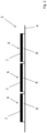
- prinzipielle Seitenansicht eines Stanzlingsbandes.
-
Fig. 1 zeigt den prinzipiellen Aufbau eines erfindungsgemäßen Stanzlingsapplikators; ein Gehäuse, an dem die einzelnen Bauteile angeordnet sind, sowie ein Roboterarm, an dem der Stanzlingsapplikator geführt wird, sind nicht eingezeichnet. - Der Stanzlingsapplikator umfasst eine Aufnahme 1 für eine Stanzlingsbandrolle 2. Auf der Stanzlingsbandrolle 2 ist ein Stanzlingsband 3 aufgewickelt. Die in der in der
Fig. 1 dargestellten Ausführungsform umfasst das Stanzlingsband 3, ein Linerband 4 sowie eine Schicht von auf dem Linerband 4 nebeneinander aufgebrachter, voneinander beabstandeter Stanzlinge 6. Die Anordnung der Stanzlinge 6 auf dem Linerband 4 ist inFig. 2 dargestellt. Das Linerband 4 besteht aus einem Band, das eine im Prinzip endlose Länge und eine konstante Breite sowie eine konstante Dicke aufweist. Auf dem Linerband 4 sind Stanzlinge 6 nebeneinander und voneinander beabstandet aufgebracht. Die Stanzlinge 6 sind im vorliegenden Fall paarweise formidentisch. Sie umfassen jeweils eine Trägerschicht 7 und eine Klebmasseschicht 8. Die Stanzlinge 6 sind so auf das Linerband 4 aufgebracht, dass die Klebmasseschicht 8 direkt auf das Linerband 4 aufgeklebt ist und die Klebmasseschicht 8 zwischen dem Linerband 4 und der Trägerschicht 7 angeordnet ist. Die Trägerschicht 7 dient dazu, dem Stanzling 6 die äußere Form zu geben. - Die Trägerschicht 7 besteht aus gängigen Kunststoffen; beispielhaft, aber nicht einschränkend erwähnt seien
- Polyethylen, Polypropylen - insbesondere das durch mono- oder biaxiale Streckung erzeugte orientierte Polypropylen (OPP), cyclische Olefin Copolymere (COC), Polyvinylchlorid (PVC), Polyester - insbesondere Polyethylenterephthalat (PET) und Polyethylennaphthalat (PEN), Ethylenvinylalkohol (EVOH), Polyvinylidenchlorid (PVDC), Polyvinylidenfluorid (PVDF), Polyacrylnitril (PAN), Polycarbonat (PC), Polyamid (PA), Polyethersulfon (PES) oder Polyimid (PI).
- Die Klebmasseschicht 8 besteht aus einer üblichen Haftklebmasse. Die Haftklebmasse umfasst eine Basis und eine vernetzbare Komponente, auch als Reaktivharz bezeichnet.
- Als Basis für Haftklebmassen kommen verschiedene Materialien, insbesondere unpolare Elastomere in Frage.
- Unpolare Elastomere, wie beispielsweise Vinylaromaten-Blockcopolymere, zeichnen sich dadurch aus, dass sie in unpolaren Lösungsmitteln gelöst werden können, d. h. in Lösungsmitteln und/oder Lösungsmittelgemischen, deren Polarität Ethylacetat entspricht oder die unpolarer sind. Dies sind insbesondere Lösungsmittel und/oder Lösungsmittelgemische mit einer Dielektrizitätskonstante von kleiner 6.1 [http://en.wikipedia.org/wiki/Solvent] und/oder mit Hansenparametern δP Polar ≤ 5.3; δH Hydrogen bonding ≤ 7.2 [Abbott, Steven and Hansen, Charles M. (2008) Hansen Solubility Parameters in Practice, ISBN 0-9551220-2-3 oder Hansen, Charles M. (2007) Hansen solubility parameters: a user's handbook CRC Press, ISBN 0-8493-7248-8].
- Kommen als Elastomere Blockcopolymere zum Einsatz, dann enthalten diese zumindest eine Blocksorte mit einer Erweichungstemperatur von größer 40 °C wie zum Beispiel Vinylaromate (auch teil- oder vollhydrierte Varianten), Methylmethacrylat, Cyclohexylmethacrylat, Isobornylmethacrylat und Isobornylacrylat.
- Weiter vorzugsweise enthält das Blockcopolymer eine Blocksorte mit einer Erweichungstemperatur von kleiner - 20 °C.
- Beispiele für Polymerblöcke mit niedrigen Erweichungstemperaturen ("Weichblöcke") sind Polyether wie zum Beispiel Polyethylenglykol, Polypropylenglykol oder Polytetrahydrofuran, Polydiene wie zum Beispiel Polybutadien oder Polyisopren, (teil)hydrierte Polydiene wie zum Beispiel Polyethylenbutylen, Polyethylenpropylen oder Polybutylenbutadien, Polybutylen, Polyisobutylen, Polyalkylvinylether, Polymerblöcke α,β-ungesättigter Ester wie insbesondere Acrylat-Copolymere.
- Der Weichblock ist dabei in einer Auslegung unpolar aufgebaut und enthält dann bevorzugt Butylen oder Isobutylen oder hydrierte Polydiene als Homopolymerblock oder Copolymerblock, letztere werden vorzugsweise mit sich selbst oder miteinander oder mit weiteren, besonders bevorzugt unpolaren Comonomeren copolymerisiert. Als unpolare Comonomere sind beispielsweise (teil-)hydriertes Polybutadien, (teil-)hydriertes Polyisopren und/oder Polyolefine geeignet.
- Die vernetzbare Komponente, auch als Reaktivharz bezeichnet, besteht aus einem cyclischen Ether und eignet sich für die strahlenchemische und gegebenenfalls thermische Vernetzung mit einer Erweichungstemperatur von kleiner 40 °C, bevorzugt von kleiner 20 °C.
- Bei den Reaktivharzen auf Basis cyclischer Ether handelt es sich insbesondere um Epoxide, also Verbindungen, die zumindest eine Oxiran-Gruppe tragen, oder Oxetane. Sie können aromatischer oder insbesondere aliphatischer oder cycloaliphatischer Natur sein.
- Einsetzbare Reaktivharze können monofunktionell, difunktionell, trifunktionell, tetrafunktionell oder höher funktionell bis zu polyfunktionell gestaltet sein, wobei sich die Funktionalität auf die cyclische Ethergruppe bezieht.
- Beispiele, ohne sich einschränken zu wollen, sind 3,4-Epoxycyclohexylmethyl-3',4'-epoxycyclohexancarboxylat (EEC) und Derivate, Dicyclopendadiendioxid und Derivate, 3-Ethyl-3-oxetanmethanol und Derivate, Tetrahydrophthalsäurediglycidylester und Derivate, Hexahydrophthalsäurediglycidylester und Derivate, 1,2-Ethandiglycidylether und Derivate, 1,3-Propandiglycidylether und Derivate, 1,4-Butandioldiglycidylether und Derivate, höhere 1,n-Alkandiglycidylether und Derivate, Bis-[(3,4-epoxycyclohexyl)methyl]-adipat und Derivate, Vinylcyclohexyldioxid und Derivate, 1,4-Cyclohexandimethanol-bis-(3,4-epoxycyclohexancarboxylat) und Derivate, 4,5-Epoxytetrahydrophthalsäurediglycidylester und Derivate, Bis-[1-ethyl(3-oxetanyl)methyl)ether und Derivate, Pentaerythritoltetraglycidylether und Derivate, Bisphenol-A-Digylcidylether (DGEBA), hydriertes Bisphenol-A-Diglycidylether, Bisphenol-F-Diglycidylether, hydriertes Bisphenol-F-Diglycidylether, Epoxyphenol-Novolaks, hydrierte Epoxyphenol-Novolaks, Epoxycresol-Novolaks, hydrierte Epoxycresol-Novolaks, 2-(7-Oxabicyclo)Spiro[1,3-dioxane-5,3'-[7]oxabicyclo[4.1.0]-heptane], 1,4-Bis((2,3-epoxypropoxy)methyl)cyclohexane.
- Reaktivharze können in ihrer monomeren oder auch dimeren, trimeren, usw. bis hin zu ihrer oligomeren Form eingesetzt werden.
- Gemische von Reaktivharzen untereinander, aber auch mit anderen coreaktiven Verbindungen wie Alkoholen (monofunktionell oder mehrfach funktionell) oder Vinylethern (monofunktionell oder mehrfach funktionell), sind ebenfalls möglich.
- Die Klebmasseschicht 8 ist vollflächig auf eine Seite der Trägerschicht 7 aufgebracht.
- Gemäß
Fig. 1 ist das Stanzlingsband derart auf der Stanzlingsbandrolle 2 aufgewickelt, dass das Linerband 4 wicklungsinnenseitig und die Stanzlinge 6 wicklungsaußenseitig angeordnet sind. Erfindungsgemäß ist es auch möglich so zu wickeln, dass das Linerband 4 wicklungsaußenseitig - Ein freies Ende des abgewickelten Stanzlingsbands 3 ist um eine erste Umlenkrolle 9 geführt und von dort zu einer Spendekante 11 geführt. Das Linerband 4 ist um die Spendekante 11 herumgeführt und auf einer Linerbandaufwickelrolle 12 aufgewickelt. Zwischen der Spendekante 11 und der Linerbandaufwickelrolle 12 ist eine zweite Umlenkrolle 13 angeordnet. Die Linerbandaufwickelrolle 12 ist mit einem nicht dargestellten ersten Antrieb angetrieben. Der erste Antrieb steht mit einer nicht dargestellten Steuerung in Verbindung. Durch den ersten Antrieb der Linerbandaufwickelrolle 12 wird das Linerband 4 auf der Linerbandaufwickelrolle 12 aufgewickelt und dadurch um die Spendekante 11 herumgezogen und von der Stanzlingsbandrolle 2 abgewickelt. Beim Umlenken des Stanzlingsbandes 3 um die Spendekante 11 herum in einem Winkel von etwa 180° wird der gerade an der Spendekante 11 anliegende Stanzling 6 abgelöst.
- In Laufrichtung des Stanzlingsbandes 3 vor dem äußersten vorlaufenden Ende der Spendekante 11 beginnt ein Saugriemen 14. Der Saugriemen 14 ist geschlossen und in einer länglichen Schleife angeordnet. Der Saugriemen 14 überlappt an einem einer Applikatorspitze 16 abgewandten Ende die Spendekante 11 ein Stück weit. Die Überlappung ist in
Fig. 1 nicht eingezeichnet. Zwischen dem einen Ende des Saugriemens 14 und der Spendekante 11 ist das Stanzlingsband 3 hindurchgeführt, und in diesem Überlappungsbereich löst sich der Stanzling 6 von dem Linerband 4 ab, wenn das Linerband 4 vorbefördert wird, und wird von dem Saugriemen 14 aufgenommen. - Der Saugriemen 14 besteht aus einem umlaufenden Endlosband, das Perforationen aufweist, wobei in einem Schleifeninneren des Endlosbandes ein Absauggerät angeordnet ist, das einen Unterdruck erzeugt, der Luft durch die Perforationen von außen nach innen in die Schlaufe saugt und dadurch den Stanzling 6 außen an den Saugriemen 14 ansaugt.
- Der Saugriemen 14 weist einen zweiten Antrieb auf. Der Saugriemen 14 ist über zumindest zwei Umlenkrollen geführt, von denen die eine Umlenkrolle angetrieben ist. Es können jedoch auch mehrere Umlenkrollen vorgesehen sein. Der Saugriemen weist an der Applikatorspitze 16 eine Andrückfläche 17 auf. Die Andrückfläche 17 kann eben ausgebildet sein, sie kann jedoch auch nach außen konvex ausgebogen sein. Der Saugriemen 14 läuft während des Betriebs über die Applikatorspitze 16 hinweg und befördert dabei Stanzlinge 6 über die Applikatorspitze 16 und über die Andrückfläche 17. Die Stanzlinge 6 berühren mit ihrer Trägerschicht 7 direkt den Saugriemen 14, während die Klebmasseschicht 8 dem Saugriemen 14 abgewandt auf der Trägerschicht 7 angeordnet ist. Der zweite Antrieb des Saugriemens 14 ist ebenfalls mit der Steuerung datenleitend verbunden. An der Applikatorspitze16 ist ein (nicht eingezeichneter) Sensor vorgesehen, der das Vorhandensein einer der Stanzlinge 6 an der Applikatorspitze 16 auf der Andrückfläche 17 erfasst. Der Sensor ist ebenfalls mit der Steuerung datenleitend verbunden.
- Die Steuerung treibt den ersten Antrieb der Linerbandaufwickelrolle 12 an. Dadurch wird das Stanzlingsband 3 von der Stanzlingsbandrolle 2 abgerollt, und zunächst wird der Stanzling 6 durch Umlenken des Linerbandes 4 um die Spendekante 11 abgelöst und ein Stück weit über den Saugriemen 14 geführt. Die Steuerung steht auch mit einem Absauggerät in Verbindung, und die Steuerung aktiviert das Absauggerät vor dem Anschalten des ersten Antriebs. Der an der Spendekante 11 abgelöste Stanzling 6 wird von dem Saugriemen 14 angesogen. Die Steuerung aktiviert den zweiten Antrieb des Saugriemens 14 und transportiert so den Stanzling 6 in Richtung der Applikatorspitze 16, während gleichzeitig das Linerband 4 aufgewickelt wird. Der Stanzling 6 wird kontinuierlich vom Linerband 4 abgelöst und vom Saugriemen 14 zur Applikatorspitze 16 weitergeführt. Die Geschwindigkeit des Linerbandes 4 an der Spendekante 11 ist genauso groß wie die Geschwindigkeit des Saugriemens 14 in Richtung der Applikatorspitze 16. Die Geschwindigkeiten sind parallel zueinander ausgerichtet. Die Stanzlinge 6 werden nacheinander vom Stanzlingsband 4 abgelöst. Der Saugriemen 14 läuft so lange, bis ein erster Stanzling 6 auf der Andrückfläche 17 positioniert ist. Dort wird das Vorhandensein des Stanzling 6 mittels des Sensors detektiert und der zweite Antrieb des Saugriemens 14 gestoppt. Gleichzeitig wird der erste Antrieb der Linerbandaufwickelrolle 12 gestoppt. Während des Transportes des Stanzlings 6 oder anschließend oder vorher wird die Andrückfläche 17 über einen vorbestimmten Bereich einer zu beklebenden Oberfläche 18 bewegt und dort ein Stück weit von der Oberfläche 18 beabstandet gestoppt. Die Andrückfläche 17 wird dann mit ihrem auf der Andrückfläche 17 positionierten Stanzling 6 in einer zur Oberfläche 18 senkrechten Bewegung auf die Oberfläche 18 gedrückt und auf die Oberfläche 18 aufgeklebt. Die Andrückfläche 17 wird danach wieder senkrecht zur Oberfläche 18 von der Oberfläche 18 wegverfahren, und der nächste Stanzling 6 wird auf die Andrückfläche 17 bewegt, indem der zweite Antrieb und gleichzeitig der erste Antrieb wieder angeschaltet werden, bis durch den Sensor detektiert wird, dass der nächste Stanzling 6 auf der Andrückfläche 17 positioniert ist. Währenddessen, vorher oder nachher wird der Stanzlingsapplikator mittels des Roboterarmes bewegt und die Andrückfläche 17 über eine zweite vorbestimmte Position bewegt. Dort wird der entsprechende Andrückvorgang wiederholt. Der Stanzlingsapplikator eignet sich insbesondere zum Verschließen von Öffnungen 20 in Karosserien. Die Stanzlinge 6 sind dann etwas größer gewählt als die zu verschließende Öffnung 20, und die Stanzlinge 6 können mit der Andrückfläche 17 auf die zu verschließende Öffnung 20 geklebt werden, indem der Stanzling 6 außen am Rand um die Öffnung 20 herum auf die Karosserie aufgeklebt und dort angedrückt wird.
-
- 1
- Aufnahme
- 2
- Stanzlingsbandrolle
- 3
- Stanzlingsband
- 4
- Linerband
- 6
- Stanzling
- 7
- Trägerschicht
- 8
- Klebmasseschicht
- 9
- erste Umlenkrolle
- 11
- Spendekante
- 12
- Linerbandaufwickelrolle
- 13
- zweite Umlenkrolle
- 14
- Saugriemen
- 16
- Applikatorspitze
- 17
- Andrückfläche
- 18
- Oberfläche
- 20
- Öffnung
Claims (5)
- Stanzlingsapplikator miteiner Stanzlingsbandrolle (2) aus einem Stanzlingsband (3), umfassend ein Linerband (4) und auf dem Linerband (4) in einer Längsrichtung voneinander separiert angeordneten Stanzlingen (6),einer Linerbandaufwickelrolle (12),einer in Laufrichtung zwischen der Stanzlingsbandrolle (2) und der Linerbandaufwickelrolle (12) angeordneten Spendekante (11), um die das Linerband (4) abziehbar ist,einem an der Spendekante (11) angeordneten Saugriemen (14) mit einer Andrückfläche (17) an einer Applikatorspitze (16), auf der ein vom Stanzlingsband (3) abgelöster und an den Saugriemen (14) übergebener Stanzling (6) positionierbar ist.gekennzeichnet durch eine Steuerung, die mit einem ersten Antrieb für die Linerbandaufwickelrolle (12) verbunden ist und einem zweiten Antrieb für den Saugriemen (14) verbunden ist und die die Geschwindigkeiten der Linerbandaufwickelrolle (12) und des Saugriemens (14) aufeinander abstimmt und gekennzeichnet durch einen Roboterarm, an dem der Saugriemen (14) angeordnet ist und der mit der Steuerung verbunden ist, die die Andrückfläche (17) mit dem auf ihr positionierten Stanzling (6) in einer senkrechten Bewegung auf eine Oberfläche (18) andrückt.
- Stanzlingsapplikator nach Anspruch 1,
dadurch gekennzeichnet, dass die Andrückfläche (17) die Größe und Kontur der Stanzlinge (6) aufweist und die Stanzlinge (6) gleich ausgeformt sind. - Stanzlingsapplikator nach Anspruch 1 oder 2,
dadurch gekennzeichnet, dass die Spendekante (11) ein Stück weit mit dem Saugriemen (14) überlappt und das Stanzlingsband (3) zwischen der Spendekante (11) und dem Saugriemen (14) hindurchgeführt ist. - Verfahren zur Applikation eines Stanzlings (6) auf einer Oberfläche (18), indem
ein Stanzlingsband (3) von einer Stanzlingsbandrolle (2) abgerollt wird und um eine Umlenkkante geführt wird und der Stanzling (6) dort vom Stanzlingsband (3) abgelöst wird und an einen Saugriemen (14) übergeben wird, der den abgelösten Stanzling (6) auf eine Andrückfläche (17) an einer Applikatorspitze (16) befördert und mit der Andrückfläche (17) den auf ihr positionierten Stanzling (6) in einer senkrechten Bewegung auf die Oberfläche (18) drückt. - Verfahren nach Anspruch 4,
dadurch gekennzeichnet, dass der Saugriemen (14) mit dem angesaugten Stanzling (6) getaktet vorbefördert wird, bis der Stanzling (6) auf der Andrückfläche (17) positioniert ist und den Saugriemen (14) dann stoppt.
Applications Claiming Priority (1)
| Application Number | Priority Date | Filing Date | Title |
|---|---|---|---|
| DE102018207469.0A DE102018207469A1 (de) | 2018-05-15 | 2018-05-15 | Stanzlingsapplikator und Verfahren zur Applikation eines Stanzlings |
Publications (2)
| Publication Number | Publication Date |
|---|---|
| EP3569534A1 EP3569534A1 (de) | 2019-11-20 |
| EP3569534B1 true EP3569534B1 (de) | 2025-07-02 |
Family
ID=66554156
Family Applications (1)
| Application Number | Title | Priority Date | Filing Date |
|---|---|---|---|
| EP19174000.0A Active EP3569534B1 (de) | 2018-05-15 | 2019-05-13 | Stanzlingsapplikator und verfahren zur applikation eines stanzlings |
Country Status (7)
| Country | Link |
|---|---|
| US (1) | US20190352034A1 (de) |
| EP (1) | EP3569534B1 (de) |
| JP (1) | JP2020033182A (de) |
| KR (1) | KR20190130973A (de) |
| CN (1) | CN110481925B (de) |
| DE (1) | DE102018207469A1 (de) |
| ES (1) | ES3036084T3 (de) |
Families Citing this family (3)
| Publication number | Priority date | Publication date | Assignee | Title |
|---|---|---|---|---|
| TWI707776B (zh) * | 2019-12-30 | 2020-10-21 | 輝能科技股份有限公司 | 氣浮式薄膜貼合設備及其氣浮滾輪 |
| DE102022125422A1 (de) | 2022-09-30 | 2024-04-04 | Tesa Se | Applikationsvorrichtung mit Nachfüllkassette |
| DE102022134629B3 (de) * | 2022-12-22 | 2023-12-28 | Tesa Se | Applikationssystem mit Transferband |
Citations (1)
| Publication number | Priority date | Publication date | Assignee | Title |
|---|---|---|---|---|
| EP0824457B1 (de) * | 1996-03-04 | 2000-01-05 | Markem Systems Limited | Etikettiervorrichtung |
Family Cites Families (17)
| Publication number | Priority date | Publication date | Assignee | Title |
|---|---|---|---|---|
| JPS59115231A (ja) * | 1982-12-09 | 1984-07-03 | 大阪シ−リング印刷株式会社 | ラベルの印刷貼付装置 |
| JPS60110205U (ja) * | 1983-11-30 | 1985-07-26 | 株式会社寺岡精工 | ラベル貼付装置 |
| JPS6169531A (ja) * | 1984-09-07 | 1986-04-10 | 東洋製罐株式会社 | ラベル貼付装置 |
| JPH01103507U (de) * | 1987-12-28 | 1989-07-13 | ||
| JPH05139429A (ja) * | 1991-05-30 | 1993-06-08 | Osaka Sealing Insatsu Kk | ラベル貼付装置 |
| JP2540475B2 (ja) * | 1992-01-27 | 1996-10-02 | 大阪シーリング印刷株式会社 | ラベル貼付装置 |
| US5824183A (en) * | 1996-04-03 | 1998-10-20 | Crankshaw; Michael | High speed corner labeler |
| JP3893526B2 (ja) * | 1997-03-14 | 2007-03-14 | 大和製衡株式会社 | オートラベラ |
| DE102004008175A1 (de) * | 2004-02-19 | 2005-09-01 | Sentelic Corporation | Vorrichtung zum Kleben von Schutzfolien und zum Prüfen |
| JP2006056584A (ja) * | 2004-08-23 | 2006-03-02 | Sato Corp | ラベル貼付装置 |
| JP2006137488A (ja) * | 2004-11-12 | 2006-06-01 | Michiharu Todo | ラベル自動貼付機 |
| JP4885483B2 (ja) * | 2005-06-06 | 2012-02-29 | リンテック株式会社 | 転写装置とその方法、剥離装置とその方法、貼付装置とその方法 |
| JP2010202274A (ja) * | 2009-03-06 | 2010-09-16 | Lintec Corp | シート貼付装置及び貼付方法 |
| JP5452173B2 (ja) * | 2009-10-30 | 2014-03-26 | リンテック株式会社 | シート貼付装置および貼付方法 |
| JP2011195197A (ja) * | 2010-02-26 | 2011-10-06 | Takara Pac Ltd | ラベル高速移送貼着装置 |
| JP5966354B2 (ja) * | 2011-12-26 | 2016-08-10 | 株式会社寺岡精工 | ラベル貼付システム |
| JP2017065685A (ja) * | 2015-09-28 | 2017-04-06 | 株式会社不二レーベル | 吸着ユニット及びラベル貼付装置 |
-
2018
- 2018-05-15 DE DE102018207469.0A patent/DE102018207469A1/de not_active Withdrawn
-
2019
- 2019-05-10 US US16/409,512 patent/US20190352034A1/en not_active Abandoned
- 2019-05-13 ES ES19174000T patent/ES3036084T3/es active Active
- 2019-05-13 EP EP19174000.0A patent/EP3569534B1/de active Active
- 2019-05-14 JP JP2019091109A patent/JP2020033182A/ja active Pending
- 2019-05-14 KR KR1020190056282A patent/KR20190130973A/ko not_active Abandoned
- 2019-05-15 CN CN201910403348.8A patent/CN110481925B/zh active Active
Patent Citations (1)
| Publication number | Priority date | Publication date | Assignee | Title |
|---|---|---|---|---|
| EP0824457B1 (de) * | 1996-03-04 | 2000-01-05 | Markem Systems Limited | Etikettiervorrichtung |
Also Published As
| Publication number | Publication date |
|---|---|
| CN110481925B (zh) | 2022-04-26 |
| US20190352034A1 (en) | 2019-11-21 |
| CN110481925A (zh) | 2019-11-22 |
| ES3036084T3 (en) | 2025-09-12 |
| KR20190130973A (ko) | 2019-11-25 |
| JP2020033182A (ja) | 2020-03-05 |
| DE102018207469A1 (de) | 2019-11-21 |
| EP3569534A1 (de) | 2019-11-20 |
Similar Documents
| Publication | Publication Date | Title |
|---|---|---|
| EP3511256B1 (de) | System und verfahren zum aufbringen von stanzteilen auf oberflächen | |
| EP1711915B1 (de) | Verfahren und vorrichtung zum kontinuierlichen herstellen elektronischer folienbauteile sowie elektronisches folienbauteil | |
| EP3569534A1 (de) | Stanzlingsapplikator und verfahren zur applikation eines stanzlings | |
| EP2478550B1 (de) | Abziehrolle, vorrichtung und verfahren zum ablösen einer folie von einem scheibenförmigen werkstück | |
| EP2205432B1 (de) | Verfahren zur herstellung von bandware mit diagnostischen hilfsmitteln | |
| DE102018217921A1 (de) | Applikationseinheit und Verfahren zur Verarbeitung von selbstklebenden Stanzteilen zum Verschluss von Öffnungen in einem Fahrzeugelement | |
| EP3587316A1 (de) | Stanzteilapplikator und verfahren zum aufbringen von stanzteilen auf oberflächen sowie ein stanzteilband | |
| EP2961367B1 (de) | Windelverschlussband sowie verfahren und vorrichtung zu dessen herstellung | |
| DE112006002846T5 (de) | Bandaufklebevorrichtung, Montagevorrichtung und Montageverfahren | |
| EP2208554B1 (de) | Verfahren und Vorrichtung zur Herstellung von Aufreissdeckeln | |
| DE4239846C2 (de) | Verfahren und Vorrichtung zur Herstellung von Diebstahlsicherungsetiketten | |
| WO2024069005A1 (de) | Applikationsvorrichtung mit nachfüllkassette | |
| EP3601123A1 (de) | Applikator für stanzlinge | |
| WO2019215064A1 (de) | Verfahren zur herstellung zweiseitig klebender klebebänder mit in längsrichtung versetzt angeordneten klebabschnitten | |
| EP3844801A1 (de) | Übertragen elektronischer bauteile von einem ersten zu einem zweiten träger | |
| EP4663565A1 (de) | Applikationseinheit und verfahren zur verarbeitung von selbstklebenden stanzteilen zum verschluss von öffnungen in einem fahrzeugelement wie batteriegehäusen | |
| EP4124449A1 (de) | Etikett, etikettenband und verfahren zum herstellen von etiketten | |
| DE102024116852A1 (de) | Applikationseinheit und Verfahren zur Verarbeitung von selbstklebenden Stanzteilen zum Verschluss von Öffnungen in einem Fahrzeugelement wie Batteriegehäusen | |
| DE102004005959A1 (de) | System und Verfahren zum Aufbringen eines selbstklebenden Etiketts auf ein Objekt | |
| WO2017050478A1 (de) | Verfahren zur handhabung von vorratsrollen mit flaechigem bandmaterial, vorratsrolle und vorrichtung zum bereitstellen flaechigen bandmaterials | |
| DE1753634C (de) | Verfahren, Klebstoff und Vorrichtung zum Bilden eines Kreuzbodens an einem Schlauch stuck zur Herstellung eines Kreuzbodensackes |
Legal Events
| Date | Code | Title | Description |
|---|---|---|---|
| PUAI | Public reference made under article 153(3) epc to a published international application that has entered the european phase |
Free format text: ORIGINAL CODE: 0009012 |
|
| STAA | Information on the status of an ep patent application or granted ep patent |
Free format text: STATUS: THE APPLICATION HAS BEEN PUBLISHED |
|
| AK | Designated contracting states |
Kind code of ref document: A1 Designated state(s): AL AT BE BG CH CY CZ DE DK EE ES FI FR GB GR HR HU IE IS IT LI LT LU LV MC MK MT NL NO PL PT RO RS SE SI SK SM TR |
|
| AX | Request for extension of the european patent |
Extension state: BA ME |
|
| STAA | Information on the status of an ep patent application or granted ep patent |
Free format text: STATUS: REQUEST FOR EXAMINATION WAS MADE |
|
| 17P | Request for examination filed |
Effective date: 20200520 |
|
| RBV | Designated contracting states (corrected) |
Designated state(s): AL AT BE BG CH CY CZ DE DK EE ES FI FR GB GR HR HU IE IS IT LI LT LU LV MC MK MT NL NO PL PT RO RS SE SI SK SM TR |
|
| STAA | Information on the status of an ep patent application or granted ep patent |
Free format text: STATUS: EXAMINATION IS IN PROGRESS |
|
| 17Q | First examination report despatched |
Effective date: 20230913 |
|
| GRAP | Despatch of communication of intention to grant a patent |
Free format text: ORIGINAL CODE: EPIDOSNIGR1 |
|
| STAA | Information on the status of an ep patent application or granted ep patent |
Free format text: STATUS: GRANT OF PATENT IS INTENDED |
|
| INTG | Intention to grant announced |
Effective date: 20250130 |
|
| GRAS | Grant fee paid |
Free format text: ORIGINAL CODE: EPIDOSNIGR3 |
|
| GRAA | (expected) grant |
Free format text: ORIGINAL CODE: 0009210 |
|
| STAA | Information on the status of an ep patent application or granted ep patent |
Free format text: STATUS: THE PATENT HAS BEEN GRANTED |
|
| AK | Designated contracting states |
Kind code of ref document: B1 Designated state(s): AL AT BE BG CH CY CZ DE DK EE ES FI FR GB GR HR HU IE IS IT LI LT LU LV MC MK MT NL NO PL PT RO RS SE SI SK SM TR |
|
| REG | Reference to a national code |
Ref country code: GB Ref legal event code: FG4D Free format text: NOT ENGLISH |
|
| REG | Reference to a national code |
Ref country code: CH Ref legal event code: EP |
|
| REG | Reference to a national code |
Ref country code: DE Ref legal event code: R096 Ref document number: 502019013535 Country of ref document: DE |
|
| REG | Reference to a national code |
Ref country code: IE Ref legal event code: FG4D Free format text: LANGUAGE OF EP DOCUMENT: GERMAN |
|
| REG | Reference to a national code |
Ref country code: ES Ref legal event code: FG2A Ref document number: 3036084 Country of ref document: ES Kind code of ref document: T3 Effective date: 20250912 |
|
| REG | Reference to a national code |
Ref country code: NL Ref legal event code: MP Effective date: 20250702 |
|
| PG25 | Lapsed in a contracting state [announced via postgrant information from national office to epo] |
Ref country code: PT Free format text: LAPSE BECAUSE OF FAILURE TO SUBMIT A TRANSLATION OF THE DESCRIPTION OR TO PAY THE FEE WITHIN THE PRESCRIBED TIME-LIMIT Effective date: 20251103 |
|
| PG25 | Lapsed in a contracting state [announced via postgrant information from national office to epo] |
Ref country code: NL Free format text: LAPSE BECAUSE OF FAILURE TO SUBMIT A TRANSLATION OF THE DESCRIPTION OR TO PAY THE FEE WITHIN THE PRESCRIBED TIME-LIMIT Effective date: 20250702 |
|
| PG25 | Lapsed in a contracting state [announced via postgrant information from national office to epo] |
Ref country code: IS Free format text: LAPSE BECAUSE OF FAILURE TO SUBMIT A TRANSLATION OF THE DESCRIPTION OR TO PAY THE FEE WITHIN THE PRESCRIBED TIME-LIMIT Effective date: 20251102 |
|
| PG25 | Lapsed in a contracting state [announced via postgrant information from national office to epo] |
Ref country code: NO Free format text: LAPSE BECAUSE OF FAILURE TO SUBMIT A TRANSLATION OF THE DESCRIPTION OR TO PAY THE FEE WITHIN THE PRESCRIBED TIME-LIMIT Effective date: 20251002 |
|
| REG | Reference to a national code |
Ref country code: LT Ref legal event code: MG9D |
|
| PG25 | Lapsed in a contracting state [announced via postgrant information from national office to epo] |
Ref country code: FI Free format text: LAPSE BECAUSE OF FAILURE TO SUBMIT A TRANSLATION OF THE DESCRIPTION OR TO PAY THE FEE WITHIN THE PRESCRIBED TIME-LIMIT Effective date: 20250702 |
|
| PG25 | Lapsed in a contracting state [announced via postgrant information from national office to epo] |
Ref country code: HR Free format text: LAPSE BECAUSE OF FAILURE TO SUBMIT A TRANSLATION OF THE DESCRIPTION OR TO PAY THE FEE WITHIN THE PRESCRIBED TIME-LIMIT Effective date: 20250702 |
|
| PG25 | Lapsed in a contracting state [announced via postgrant information from national office to epo] |
Ref country code: GR Free format text: LAPSE BECAUSE OF FAILURE TO SUBMIT A TRANSLATION OF THE DESCRIPTION OR TO PAY THE FEE WITHIN THE PRESCRIBED TIME-LIMIT Effective date: 20251003 |
|
| PG25 | Lapsed in a contracting state [announced via postgrant information from national office to epo] |
Ref country code: SE Free format text: LAPSE BECAUSE OF FAILURE TO SUBMIT A TRANSLATION OF THE DESCRIPTION OR TO PAY THE FEE WITHIN THE PRESCRIBED TIME-LIMIT Effective date: 20250702 Ref country code: CZ Free format text: LAPSE BECAUSE OF FAILURE TO SUBMIT A TRANSLATION OF THE DESCRIPTION OR TO PAY THE FEE WITHIN THE PRESCRIBED TIME-LIMIT Effective date: 20250702 |
|
| PG25 | Lapsed in a contracting state [announced via postgrant information from national office to epo] |
Ref country code: LV Free format text: LAPSE BECAUSE OF FAILURE TO SUBMIT A TRANSLATION OF THE DESCRIPTION OR TO PAY THE FEE WITHIN THE PRESCRIBED TIME-LIMIT Effective date: 20250702 |
|
| PG25 | Lapsed in a contracting state [announced via postgrant information from national office to epo] |
Ref country code: BG Free format text: LAPSE BECAUSE OF FAILURE TO SUBMIT A TRANSLATION OF THE DESCRIPTION OR TO PAY THE FEE WITHIN THE PRESCRIBED TIME-LIMIT Effective date: 20250702 Ref country code: PL Free format text: LAPSE BECAUSE OF FAILURE TO SUBMIT A TRANSLATION OF THE DESCRIPTION OR TO PAY THE FEE WITHIN THE PRESCRIBED TIME-LIMIT Effective date: 20250702 |
|
| PG25 | Lapsed in a contracting state [announced via postgrant information from national office to epo] |
Ref country code: RS Free format text: LAPSE BECAUSE OF FAILURE TO SUBMIT A TRANSLATION OF THE DESCRIPTION OR TO PAY THE FEE WITHIN THE PRESCRIBED TIME-LIMIT Effective date: 20251002 |
|
| PG25 | Lapsed in a contracting state [announced via postgrant information from national office to epo] |
Ref country code: SM Free format text: LAPSE BECAUSE OF FAILURE TO SUBMIT A TRANSLATION OF THE DESCRIPTION OR TO PAY THE FEE WITHIN THE PRESCRIBED TIME-LIMIT Effective date: 20250702 |
|
| PG25 | Lapsed in a contracting state [announced via postgrant information from national office to epo] |
Ref country code: DK Free format text: LAPSE BECAUSE OF FAILURE TO SUBMIT A TRANSLATION OF THE DESCRIPTION OR TO PAY THE FEE WITHIN THE PRESCRIBED TIME-LIMIT Effective date: 20250702 |
|
| PG25 | Lapsed in a contracting state [announced via postgrant information from national office to epo] |
Ref country code: IT Free format text: LAPSE BECAUSE OF FAILURE TO SUBMIT A TRANSLATION OF THE DESCRIPTION OR TO PAY THE FEE WITHIN THE PRESCRIBED TIME-LIMIT Effective date: 20250702 |
|
| PG25 | Lapsed in a contracting state [announced via postgrant information from national office to epo] |
Ref country code: EE Free format text: LAPSE BECAUSE OF FAILURE TO SUBMIT A TRANSLATION OF THE DESCRIPTION OR TO PAY THE FEE WITHIN THE PRESCRIBED TIME-LIMIT Effective date: 20250702 Ref country code: SK Free format text: LAPSE BECAUSE OF FAILURE TO SUBMIT A TRANSLATION OF THE DESCRIPTION OR TO PAY THE FEE WITHIN THE PRESCRIBED TIME-LIMIT Effective date: 20250702 |
|
| PLBE | No opposition filed within time limit |
Free format text: ORIGINAL CODE: 0009261 |
|
| STAA | Information on the status of an ep patent application or granted ep patent |
Free format text: STATUS: NO OPPOSITION FILED WITHIN TIME LIMIT |