EP3566918A1 - Hybridfahrzeug mit intelligentem fahrzeugsteuergerät - Google Patents
Hybridfahrzeug mit intelligentem fahrzeugsteuergerät Download PDFInfo
- Publication number
- EP3566918A1 EP3566918A1 EP19173542.2A EP19173542A EP3566918A1 EP 3566918 A1 EP3566918 A1 EP 3566918A1 EP 19173542 A EP19173542 A EP 19173542A EP 3566918 A1 EP3566918 A1 EP 3566918A1
- Authority
- EP
- European Patent Office
- Prior art keywords
- ice
- desirable
- power level
- vehicle controller
- intelligent vehicle
- Prior art date
- Legal status (The legal status is an assumption and is not a legal conclusion. Google has not performed a legal analysis and makes no representation as to the accuracy of the status listed.)
- Pending
Links
Images


Classifications
-
- B—PERFORMING OPERATIONS; TRANSPORTING
- B60—VEHICLES IN GENERAL
- B60W—CONJOINT CONTROL OF VEHICLE SUB-UNITS OF DIFFERENT TYPE OR DIFFERENT FUNCTION; CONTROL SYSTEMS SPECIALLY ADAPTED FOR HYBRID VEHICLES; ROAD VEHICLE DRIVE CONTROL SYSTEMS FOR PURPOSES NOT RELATED TO THE CONTROL OF A PARTICULAR SUB-UNIT
- B60W20/00—Control systems specially adapted for hybrid vehicles
- B60W20/10—Controlling the power contribution of each of the prime movers to meet required power demand
- B60W20/13—Controlling the power contribution of each of the prime movers to meet required power demand in order to stay within battery power input or output limits; in order to prevent overcharging or battery depletion
-
- B—PERFORMING OPERATIONS; TRANSPORTING
- B60—VEHICLES IN GENERAL
- B60K—ARRANGEMENT OR MOUNTING OF PROPULSION UNITS OR OF TRANSMISSIONS IN VEHICLES; ARRANGEMENT OR MOUNTING OF PLURAL DIVERSE PRIME-MOVERS IN VEHICLES; AUXILIARY DRIVES FOR VEHICLES; INSTRUMENTATION OR DASHBOARDS FOR VEHICLES; ARRANGEMENTS IN CONNECTION WITH COOLING, AIR INTAKE, GAS EXHAUST OR FUEL SUPPLY OF PROPULSION UNITS IN VEHICLES
- B60K6/00—Arrangement or mounting of plural diverse prime-movers for mutual or common propulsion, e.g. hybrid propulsion systems comprising electric motors and internal combustion engines ; Control systems therefor, i.e. systems controlling two or more prime movers, or controlling one of these prime movers and any of the transmission, drive or drive units Informative references: mechanical gearings with secondary electric drive F16H3/72; arrangements for handling mechanical energy structurally associated with the dynamo-electric machine H02K7/00; machines comprising structurally interrelated motor and generator parts H02K51/00; dynamo-electric machines not otherwise provided for in H02K see H02K99/00
- B60K6/20—Arrangement or mounting of plural diverse prime-movers for mutual or common propulsion, e.g. hybrid propulsion systems comprising electric motors and internal combustion engines ; Control systems therefor, i.e. systems controlling two or more prime movers, or controlling one of these prime movers and any of the transmission, drive or drive units Informative references: mechanical gearings with secondary electric drive F16H3/72; arrangements for handling mechanical energy structurally associated with the dynamo-electric machine H02K7/00; machines comprising structurally interrelated motor and generator parts H02K51/00; dynamo-electric machines not otherwise provided for in H02K see H02K99/00 the prime-movers consisting of electric motors and internal combustion engines, e.g. HEVs
- B60K6/42—Arrangement or mounting of plural diverse prime-movers for mutual or common propulsion, e.g. hybrid propulsion systems comprising electric motors and internal combustion engines ; Control systems therefor, i.e. systems controlling two or more prime movers, or controlling one of these prime movers and any of the transmission, drive or drive units Informative references: mechanical gearings with secondary electric drive F16H3/72; arrangements for handling mechanical energy structurally associated with the dynamo-electric machine H02K7/00; machines comprising structurally interrelated motor and generator parts H02K51/00; dynamo-electric machines not otherwise provided for in H02K see H02K99/00 the prime-movers consisting of electric motors and internal combustion engines, e.g. HEVs characterised by the architecture of the hybrid electric vehicle
- B60K6/46—Series type
-
- B—PERFORMING OPERATIONS; TRANSPORTING
- B60—VEHICLES IN GENERAL
- B60L—PROPULSION OF ELECTRICALLY-PROPELLED VEHICLES; SUPPLYING ELECTRIC POWER FOR AUXILIARY EQUIPMENT OF ELECTRICALLY-PROPELLED VEHICLES; ELECTRODYNAMIC BRAKE SYSTEMS FOR VEHICLES IN GENERAL; MAGNETIC SUSPENSION OR LEVITATION FOR VEHICLES; MONITORING OPERATING VARIABLES OF ELECTRICALLY-PROPELLED VEHICLES; ELECTRIC SAFETY DEVICES FOR ELECTRICALLY-PROPELLED VEHICLES
- B60L50/00—Electric propulsion with power supplied within the vehicle
- B60L50/50—Electric propulsion with power supplied within the vehicle using propulsion power supplied by batteries or fuel cells
- B60L50/60—Electric propulsion with power supplied within the vehicle using propulsion power supplied by batteries or fuel cells using power supplied by batteries
- B60L50/61—Electric propulsion with power supplied within the vehicle using propulsion power supplied by batteries or fuel cells using power supplied by batteries by batteries charged by engine-driven generators, e.g. series hybrid electric vehicles
- B60L50/62—Electric propulsion with power supplied within the vehicle using propulsion power supplied by batteries or fuel cells using power supplied by batteries by batteries charged by engine-driven generators, e.g. series hybrid electric vehicles charged by low-power generators primarily intended to support the batteries, e.g. range extenders
-
- B—PERFORMING OPERATIONS; TRANSPORTING
- B60—VEHICLES IN GENERAL
- B60W—CONJOINT CONTROL OF VEHICLE SUB-UNITS OF DIFFERENT TYPE OR DIFFERENT FUNCTION; CONTROL SYSTEMS SPECIALLY ADAPTED FOR HYBRID VEHICLES; ROAD VEHICLE DRIVE CONTROL SYSTEMS FOR PURPOSES NOT RELATED TO THE CONTROL OF A PARTICULAR SUB-UNIT
- B60W10/00—Conjoint control of vehicle sub-units of different type or different function
- B60W10/04—Conjoint control of vehicle sub-units of different type or different function including control of propulsion units
- B60W10/06—Conjoint control of vehicle sub-units of different type or different function including control of propulsion units including control of combustion engines
-
- B—PERFORMING OPERATIONS; TRANSPORTING
- B60—VEHICLES IN GENERAL
- B60W—CONJOINT CONTROL OF VEHICLE SUB-UNITS OF DIFFERENT TYPE OR DIFFERENT FUNCTION; CONTROL SYSTEMS SPECIALLY ADAPTED FOR HYBRID VEHICLES; ROAD VEHICLE DRIVE CONTROL SYSTEMS FOR PURPOSES NOT RELATED TO THE CONTROL OF A PARTICULAR SUB-UNIT
- B60W10/00—Conjoint control of vehicle sub-units of different type or different function
- B60W10/04—Conjoint control of vehicle sub-units of different type or different function including control of propulsion units
- B60W10/08—Conjoint control of vehicle sub-units of different type or different function including control of propulsion units including control of electric propulsion units, e.g. motors or generators
-
- B—PERFORMING OPERATIONS; TRANSPORTING
- B60—VEHICLES IN GENERAL
- B60W—CONJOINT CONTROL OF VEHICLE SUB-UNITS OF DIFFERENT TYPE OR DIFFERENT FUNCTION; CONTROL SYSTEMS SPECIALLY ADAPTED FOR HYBRID VEHICLES; ROAD VEHICLE DRIVE CONTROL SYSTEMS FOR PURPOSES NOT RELATED TO THE CONTROL OF A PARTICULAR SUB-UNIT
- B60W10/00—Conjoint control of vehicle sub-units of different type or different function
- B60W10/24—Conjoint control of vehicle sub-units of different type or different function including control of energy storage means
- B60W10/26—Conjoint control of vehicle sub-units of different type or different function including control of energy storage means for electrical energy, e.g. batteries or capacitors
-
- B—PERFORMING OPERATIONS; TRANSPORTING
- B60—VEHICLES IN GENERAL
- B60W—CONJOINT CONTROL OF VEHICLE SUB-UNITS OF DIFFERENT TYPE OR DIFFERENT FUNCTION; CONTROL SYSTEMS SPECIALLY ADAPTED FOR HYBRID VEHICLES; ROAD VEHICLE DRIVE CONTROL SYSTEMS FOR PURPOSES NOT RELATED TO THE CONTROL OF A PARTICULAR SUB-UNIT
- B60W20/00—Control systems specially adapted for hybrid vehicles
- B60W20/10—Controlling the power contribution of each of the prime movers to meet required power demand
- B60W20/11—Controlling the power contribution of each of the prime movers to meet required power demand using model predictive control [MPC] strategies, i.e. control methods based on models predicting performance
-
- B—PERFORMING OPERATIONS; TRANSPORTING
- B60—VEHICLES IN GENERAL
- B60W—CONJOINT CONTROL OF VEHICLE SUB-UNITS OF DIFFERENT TYPE OR DIFFERENT FUNCTION; CONTROL SYSTEMS SPECIALLY ADAPTED FOR HYBRID VEHICLES; ROAD VEHICLE DRIVE CONTROL SYSTEMS FOR PURPOSES NOT RELATED TO THE CONTROL OF A PARTICULAR SUB-UNIT
- B60W20/00—Control systems specially adapted for hybrid vehicles
- B60W20/10—Controlling the power contribution of each of the prime movers to meet required power demand
- B60W20/15—Control strategies specially adapted for achieving a particular effect
- B60W20/16—Control strategies specially adapted for achieving a particular effect for reducing engine exhaust emissions
-
- B—PERFORMING OPERATIONS; TRANSPORTING
- B60—VEHICLES IN GENERAL
- B60W—CONJOINT CONTROL OF VEHICLE SUB-UNITS OF DIFFERENT TYPE OR DIFFERENT FUNCTION; CONTROL SYSTEMS SPECIALLY ADAPTED FOR HYBRID VEHICLES; ROAD VEHICLE DRIVE CONTROL SYSTEMS FOR PURPOSES NOT RELATED TO THE CONTROL OF A PARTICULAR SUB-UNIT
- B60W20/00—Control systems specially adapted for hybrid vehicles
- B60W20/10—Controlling the power contribution of each of the prime movers to meet required power demand
- B60W20/15—Control strategies specially adapted for achieving a particular effect
- B60W20/17—Control strategies specially adapted for achieving a particular effect for noise reduction
-
- B—PERFORMING OPERATIONS; TRANSPORTING
- B60—VEHICLES IN GENERAL
- B60W—CONJOINT CONTROL OF VEHICLE SUB-UNITS OF DIFFERENT TYPE OR DIFFERENT FUNCTION; CONTROL SYSTEMS SPECIALLY ADAPTED FOR HYBRID VEHICLES; ROAD VEHICLE DRIVE CONTROL SYSTEMS FOR PURPOSES NOT RELATED TO THE CONTROL OF A PARTICULAR SUB-UNIT
- B60W50/00—Details of control systems for road vehicle drive control not related to the control of a particular sub-unit, e.g. process diagnostic or vehicle driver interfaces
- B60W2050/0001—Details of the control system
- B60W2050/0019—Control system elements or transfer functions
- B60W2050/0022—Gains, weighting coefficients or weighting functions
- B60W2050/0025—Transfer function weighting factor
-
- B—PERFORMING OPERATIONS; TRANSPORTING
- B60—VEHICLES IN GENERAL
- B60W—CONJOINT CONTROL OF VEHICLE SUB-UNITS OF DIFFERENT TYPE OR DIFFERENT FUNCTION; CONTROL SYSTEMS SPECIALLY ADAPTED FOR HYBRID VEHICLES; ROAD VEHICLE DRIVE CONTROL SYSTEMS FOR PURPOSES NOT RELATED TO THE CONTROL OF A PARTICULAR SUB-UNIT
- B60W50/00—Details of control systems for road vehicle drive control not related to the control of a particular sub-unit, e.g. process diagnostic or vehicle driver interfaces
- B60W2050/0001—Details of the control system
- B60W2050/0019—Control system elements or transfer functions
- B60W2050/0026—Lookup tables or parameter maps
-
- B—PERFORMING OPERATIONS; TRANSPORTING
- B60—VEHICLES IN GENERAL
- B60W—CONJOINT CONTROL OF VEHICLE SUB-UNITS OF DIFFERENT TYPE OR DIFFERENT FUNCTION; CONTROL SYSTEMS SPECIALLY ADAPTED FOR HYBRID VEHICLES; ROAD VEHICLE DRIVE CONTROL SYSTEMS FOR PURPOSES NOT RELATED TO THE CONTROL OF A PARTICULAR SUB-UNIT
- B60W50/00—Details of control systems for road vehicle drive control not related to the control of a particular sub-unit, e.g. process diagnostic or vehicle driver interfaces
- B60W2050/0001—Details of the control system
- B60W2050/0019—Control system elements or transfer functions
- B60W2050/0028—Mathematical models, e.g. for simulation
- B60W2050/0037—Mathematical models of vehicle sub-units
- B60W2050/0039—Mathematical models of vehicle sub-units of the propulsion unit
-
- B—PERFORMING OPERATIONS; TRANSPORTING
- B60—VEHICLES IN GENERAL
- B60W—CONJOINT CONTROL OF VEHICLE SUB-UNITS OF DIFFERENT TYPE OR DIFFERENT FUNCTION; CONTROL SYSTEMS SPECIALLY ADAPTED FOR HYBRID VEHICLES; ROAD VEHICLE DRIVE CONTROL SYSTEMS FOR PURPOSES NOT RELATED TO THE CONTROL OF A PARTICULAR SUB-UNIT
- B60W2510/00—Input parameters relating to a particular sub-units
- B60W2510/24—Energy storage means
- B60W2510/242—Energy storage means for electrical energy
- B60W2510/244—Charge state
-
- B—PERFORMING OPERATIONS; TRANSPORTING
- B60—VEHICLES IN GENERAL
- B60W—CONJOINT CONTROL OF VEHICLE SUB-UNITS OF DIFFERENT TYPE OR DIFFERENT FUNCTION; CONTROL SYSTEMS SPECIALLY ADAPTED FOR HYBRID VEHICLES; ROAD VEHICLE DRIVE CONTROL SYSTEMS FOR PURPOSES NOT RELATED TO THE CONTROL OF A PARTICULAR SUB-UNIT
- B60W2520/00—Input parameters relating to overall vehicle dynamics
- B60W2520/10—Longitudinal speed
-
- B—PERFORMING OPERATIONS; TRANSPORTING
- B60—VEHICLES IN GENERAL
- B60W—CONJOINT CONTROL OF VEHICLE SUB-UNITS OF DIFFERENT TYPE OR DIFFERENT FUNCTION; CONTROL SYSTEMS SPECIALLY ADAPTED FOR HYBRID VEHICLES; ROAD VEHICLE DRIVE CONTROL SYSTEMS FOR PURPOSES NOT RELATED TO THE CONTROL OF A PARTICULAR SUB-UNIT
- B60W2710/00—Output or target parameters relating to a particular sub-units
- B60W2710/06—Combustion engines, Gas turbines
- B60W2710/0644—Engine speed
-
- B—PERFORMING OPERATIONS; TRANSPORTING
- B60—VEHICLES IN GENERAL
- B60W—CONJOINT CONTROL OF VEHICLE SUB-UNITS OF DIFFERENT TYPE OR DIFFERENT FUNCTION; CONTROL SYSTEMS SPECIALLY ADAPTED FOR HYBRID VEHICLES; ROAD VEHICLE DRIVE CONTROL SYSTEMS FOR PURPOSES NOT RELATED TO THE CONTROL OF A PARTICULAR SUB-UNIT
- B60W2710/00—Output or target parameters relating to a particular sub-units
- B60W2710/06—Combustion engines, Gas turbines
- B60W2710/0666—Engine torque
-
- B—PERFORMING OPERATIONS; TRANSPORTING
- B60—VEHICLES IN GENERAL
- B60W—CONJOINT CONTROL OF VEHICLE SUB-UNITS OF DIFFERENT TYPE OR DIFFERENT FUNCTION; CONTROL SYSTEMS SPECIALLY ADAPTED FOR HYBRID VEHICLES; ROAD VEHICLE DRIVE CONTROL SYSTEMS FOR PURPOSES NOT RELATED TO THE CONTROL OF A PARTICULAR SUB-UNIT
- B60W2710/00—Output or target parameters relating to a particular sub-units
- B60W2710/06—Combustion engines, Gas turbines
- B60W2710/0677—Engine power
-
- Y—GENERAL TAGGING OF NEW TECHNOLOGICAL DEVELOPMENTS; GENERAL TAGGING OF CROSS-SECTIONAL TECHNOLOGIES SPANNING OVER SEVERAL SECTIONS OF THE IPC; TECHNICAL SUBJECTS COVERED BY FORMER USPC CROSS-REFERENCE ART COLLECTIONS [XRACs] AND DIGESTS
- Y02—TECHNOLOGIES OR APPLICATIONS FOR MITIGATION OR ADAPTATION AGAINST CLIMATE CHANGE
- Y02T—CLIMATE CHANGE MITIGATION TECHNOLOGIES RELATED TO TRANSPORTATION
- Y02T10/00—Road transport of goods or passengers
- Y02T10/10—Internal combustion engine [ICE] based vehicles
- Y02T10/40—Engine management systems
-
- Y—GENERAL TAGGING OF NEW TECHNOLOGICAL DEVELOPMENTS; GENERAL TAGGING OF CROSS-SECTIONAL TECHNOLOGIES SPANNING OVER SEVERAL SECTIONS OF THE IPC; TECHNICAL SUBJECTS COVERED BY FORMER USPC CROSS-REFERENCE ART COLLECTIONS [XRACs] AND DIGESTS
- Y02—TECHNOLOGIES OR APPLICATIONS FOR MITIGATION OR ADAPTATION AGAINST CLIMATE CHANGE
- Y02T—CLIMATE CHANGE MITIGATION TECHNOLOGIES RELATED TO TRANSPORTATION
- Y02T10/00—Road transport of goods or passengers
- Y02T10/60—Other road transportation technologies with climate change mitigation effect
- Y02T10/62—Hybrid vehicles
-
- Y—GENERAL TAGGING OF NEW TECHNOLOGICAL DEVELOPMENTS; GENERAL TAGGING OF CROSS-SECTIONAL TECHNOLOGIES SPANNING OVER SEVERAL SECTIONS OF THE IPC; TECHNICAL SUBJECTS COVERED BY FORMER USPC CROSS-REFERENCE ART COLLECTIONS [XRACs] AND DIGESTS
- Y02—TECHNOLOGIES OR APPLICATIONS FOR MITIGATION OR ADAPTATION AGAINST CLIMATE CHANGE
- Y02T—CLIMATE CHANGE MITIGATION TECHNOLOGIES RELATED TO TRANSPORTATION
- Y02T10/00—Road transport of goods or passengers
- Y02T10/60—Other road transportation technologies with climate change mitigation effect
- Y02T10/70—Energy storage systems for electromobility, e.g. batteries
Definitions
- Hybrid electric vehicles having dual power sources, such as a battery, and a chemical power source, such as an internal combustion engine (ICE), are increasingly used for improving energy efficiency and emissions.
- ICE internal combustion engine
- Such hybrid electric vehicles may include intelligent power management systems capable of altering the torque or revolutions per minute (RPM) the ICE runs at.
- RPM revolutions per minute
- conventional intelligent power management systems are often reactive to the actual behavior of the hybrid electric vehicle, rather than predictive, and cannot easily account for other concerns besides driving the hybrid electric vehicle at the speed demanded by the driver.
- the present disclosure is directed to a hybrid electric vehicle using an intelligent vehicle controller, substantially as shown in and/or described in connection with at least one of the figures, and as set forth in the claims.
- FIG. 1 illustrates a diagram of a portion of an exemplary hybrid electric vehicle according to one implementation of the present application.
- hybrid electric vehicle 100 includes intelligent vehicle controller 102, internal combustion engine (ICE) 104, ICE controller 105, electrical generator 106, battery 110, battery controller 111, high voltage (HV) bus 112, inverters 114a, 114b, and 114c, electric motors 116a and 116b, rear drive wheels 118a and 118b, and variable exhaust valve 120.
- ICE internal combustion engine
- HV high voltage
- Intelligent vehicle controller 102 is connected to ICE controller 105, battery controller 111, inverters 114a, 114b, and 114c, and variable exhaust valve 120. In operation, intelligent vehicle controller 102 receives power level shifting data from these various components, determines vehicle operation points for ICE 104 using the power level shifting data, and sends a control signal to ICE controller 105 to run ICE 104 at the determined vehicle operation points.
- ICE controller 105 can be an electronic control module that controls actuators of ICE 104 to modify ignition timing, fuel pressure, air-fuel ratio, and valve timing, among other characteristics.
- intelligent vehicle controller 102 and ICE controller 105 together can run ICE 104 at desirable power levels, desirable torques, and desirable revolutions per minute (RPMs).
- ICE 104 can be generally any engine that transforms chemical power from fuel into mechanical power.
- ICE 104 can be a six cylinder piston engine.
- hybrid electric vehicle 100 has a series hybrid drivetrain, and ICE 104 is coupled to electrical generator 106.
- ICE 104 produces mechanical power and electrical generator 106 converts the mechanical power into electricity.
- Inverter 114a converts the electricity from alternating current (AC) to direct current (DC), which is then provided to battery 110 and electric motors 116a and 116b.
- Inverter 114a can be, for example, a bi-directional three-phase inverter.
- HV bus 112 carries electricity from inverter 114a to battery 110.
- Battery 110 uses the electricity to recharge its cells.
- Battery 110 can be, for example, a nickel metal hydride battery pack, a lithium ion battery pack, or any other type of battery.
- Battery controller 111 may include monitoring electronics for battery 110.
- HV bus 112 also carries electricity either from inverter 114a or from battery 110 to inverters 114b and 114c.
- Inverters 114b and 114c convert the electricity from DC to AC.
- Inverters 114b and 114c can be, for example, bi-directional three-phase inverters.
- the AC electricity is then provided to electric motors 116a and 116b. Electric motors 116a and 116b rotate rear drive wheels 118a and 118b.
- electric motors 116a and 116b rotate a gear box (not shown in Figure 1 ), which then rotates rear drive wheels 118a and 118b.
- Electric motors 116a and 116b can be, for example, induction motors, synchronous motors, reluctance motors, or any other type of electric motor.
- HV bus 112 can also carry electrical power to other components of hybrid electric vehicle 100, such as, for example, a power steering system (not shown in Figure 1 ).
- Figure 2 illustrates a portion of an exemplary intelligent vehicle controller according to one implementation of the present application.
- intelligent vehicle controller 202 includes interface unit 224, processor 226, and memory 228.
- Memory 228 includes efficiency map 230 having fuel efficiency contours 232 and noise, vibration, and/or harshness (NVH) level lines 234.
- Memory 228 optionally includes hardware component capabilities 238.
- Intelligent vehicle controller 202 in Figure 2 generally correspond to intelligent vehicle controller 102 in Figure 1 .
- Figure 2 also shows ICE controller 205, battery controller 211, inverter 214, and variable exhaust valve 220, which generally correspond to ICE controller 105, battery controller 111, inverters 214a, 214b, and 214c, and variable exhaust valve 120 respectively in Figure 1 .
- Interface unit 224 is connected to ICE controller 205, battery controller 211, and inverter 214, and optionally connected to variable exhaust valve 220. Interface unit 224 and connected components can communicate bi-directionally over a vehicle bus.
- the vehicle bus can utilize Controller Area Network (CAN) protocol, Local Interconnect Network (LIN) protocol, or any other protocol.
- Interface unit 224 receives ICE power level shifting data from ICE controller 205, battery 211, inverter 214, and variable exhaust valve 220.
- CAN Controller Area Network
- LIN Local Interconnect Network
- ICE power level shifting data is generally any data relating to a component of hybrid electric vehicle 100 that could indicate that ICE 104 should use more or less power.
- ICE power level shifting data can represent present measurements, estimates, stored data, and/or maximum safe/recommended values for preventing stress, overheating, etc.
- ICE power level shifting data from ICE controller 205 can include data regarding throttle command from a driver, temperature, power level, torque, and RPM.
- ICE power level shifting data from inverter 214 can include electrical generator capabilities, such as input power, temperature, output power, output voltage, and output current of inverter 114a in Figure 1 .
- ICE power level shifting data from inverter 214 can also include a high voltage bus demand (i.e., the power demanded by inverters 114b and 114c and auxiliary systems, such as a power steering system).
- ICE power level shifting data from battery controller 211 can include battery charge capabilities, such as capacity and charging rate.
- ICE power level shifting data from battery controller 211 can also include state-of-charge (SOC) or SOC deficit (i.e., the difference between SOC and a target SOC).
- SOC state-of-charge
- SOC deficit i.e., the difference between SOC and a target SOC
- Interface unit 224 is connect to processor 226 and provides ICE power level shifting data to processor 226.
- Processor 226 can optionally retrieve ICE power level shifting data from memory 228, for example, when ICE power level shifting data is expected to be static, rather than dynamic.
- memory 228 optionally includes hardware component capabilities 238, such as electrical generator capabilities, battery charge capabilities, and high voltage bus capabilities.
- ICE power level shifting data can be pre-programmed in memory 228, or can be stored in memory 228 after being received by intelligent vehicle controller 202 through interface unit 224.
- processor 226 of intelligent vehicle controller 202 derives a desirable power level for ICE 104 by evaluating the ICE power level shifting data, and determines a desirable torque and/or a desirable RPM for ICE 104 utilizing efficiency map 230, which includes fuel efficiency contours 232 and NVH level lines 234.
- intelligent vehicle controller 202 can advantageously use the desirable torque and/or the desirable RPM to influence operation of hybrid electric vehicle 100. For example, intelligent vehicle controller 202 can generate a control signal for ICE controller 205 based on the desirable torque and/or the desirable RPM, communicate the control signal to ICE controller 205 through interface unit 224, and use ICE controller 205 to run ICE 104 at the desirable torque and/or the desirable RPM.
- intelligent vehicle controller 202 can generate a control signal for a driver interface system (not shown in Figure 2 ) which can prompt a driver to choose whether or not to allow ICE controller 205 to run ICE 104 at the desirable torque and/or the desirable RPM.
- intelligent vehicle controller 202 can generate a control signal for variable exhaust valve 220 based on the desirable torque and/or the desirable RPM, communicate the control signal to variable exhaust valve 220 through interface unit 224, and alter exhaust flow in variable exhaust valve 220 based on the desirable torque and/or the desirable RPM.
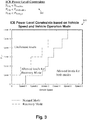
- Figure 3 illustrates a portion of an exemplary table of ICE power level constraints and a portion of an exemplary power level graph according to one implementation of the present application.
- Intelligent vehicle controller 102 in Figure 1 (or intelligent vehicle controller 202 in Figure 2 ) derives a desirable power level for ICE 104 in Figure 1 by evaluating the ICE power level shifting data.
- table 340 shows exemplary ICE power level constraints that intelligent vehicle controller 102 in Figure 1 (or intelligent vehicle controller 202 in Figure 2 ) can apply based on the received ICE power level shifting data.
- intelligent vehicle controller 102 in Figure 1 when intelligent vehicle controller 102 in Figure 1 (or intelligent vehicle controller 202 in Figure 2 ) receives an electrical generator capability, such as a maximum input power, as ICE power level shifting data, intelligent vehicle controller 102 in Figure 1 (or intelligent vehicle controller 202 in Figure 2 ) can constrain the power level of ICE 104 in Figure 1 such that it is less than a power level that would exceed the maximum input power of inverter 114a in Figure 1 (or inverter 214 in Figure 2 ) (i.e., P ICE ⁇ P GenMax ).
- intelligent vehicle controller 102 in Figure 1 can constrain the power level of ICE 104 in Figure 1 such that it is less than a power level that would exceed a maximum limit of HV bus 112 in Figure 1 (i.e., P ICE ⁇ P HVBusMax ).
- intelligent vehicle controller 102 in Figure 1 when intelligent vehicle controller 102 in Figure 1 (or intelligent vehicle controller 202 in Figure 2 ) receives a vehicle speed (presently measured or commanded by a driver) as ICE power level shifting data, intelligent vehicle controller 102 in Figure 1 (or intelligent vehicle controller 202 in Figure 2 ) can constrain the power level of ICE 104 in Figure 1 based on that vehicle speed (i.e., P ICE ⁇ P VehSpd ), as discussed below.
- power level graph 342 represents the power level of ICE 104 in Figure 1 (i.e., P ICE ), versus the speed of hybrid electric vehicle 100.
- P ICE and vehicle speed shown in Figure 3 are merely examples and are not intended to correspond to actual numerical values.
- intelligent vehicle controller 102 in Figure 1 can constrain the power level of ICE 104 in Figure 1 to only allow power levels below a given power level threshold.
- Intelligent vehicle controller 102 in Figure 1 can determine the allowed power levels for a given vehicle speed based on ICE power level shifting data, data stored in memory 228, and/or other factors.
- intelligent vehicle controller 102 in Figure 1 can use stored correlations between vehicle speeds, NVH levels, and power levels.
- intelligent vehicle controller 102 in Figure 1 When intelligent vehicle controller 102 in Figure 1 (or intelligent vehicle controller 202 in Figure 2 ) receives a vehicle speed as ICE power level shifting data, intelligent vehicle controller 102 in Figure 1 (or intelligent vehicle controller 202 in Figure 2 ) can constrain the power level of ICE 104 in Figure 1 such that it is less than a power level that would exceed an allowed NVH level (i.e., P ICE ⁇ P VehSpd ).
- P ICE ⁇ P VehSpd an allowed NVH level
- Allowed power levels can be based on other factors, such as vehicle operation modes.
- graph 342 includes two traces. Each trace corresponds to a different vehicle operation mode of intelligent vehicle controller 102 in Figure 1 (or intelligent vehicle controller 202 in Figure 2 ). Each trace represents desirable power levels for ICE 104 in Figure 1 derived by intelligent vehicle controller 102 in Figure 1 (or intelligent vehicle controller 202 in Figure 2 ) for a given vehicle operation mode.
- a vehicle operation mode refers to the ability of intelligent vehicle controller 102 in Figure 1 (or intelligent vehicle controller 202 in Figure 2 ) to evaluate ICE power level shifting data differently when deriving a desirable power level for ICE 104 in Figure 1 .
- intelligent vehicle controller 102 in Figure 1 has two operation modes, corresponding to a normal mode and a recovery mode.
- ICE 104 in Figure 1 is used sparingly as needed to maintain vehicle speed.
- the vehicle speed threshold is a fixed value between Speed 1 and Speed 2. In other implementations, the vehicle speed threshold may be any other fixed value. In another implementation, the vehicle speed threshold may dynamically depend on ICE power level shifting data received by intelligent vehicle controller 102 in Figure 1 (or intelligent vehicle controller 202 in Figure 2 ).
- the power level of ICE 104 in Figure 1 that would allow battery 110 in Figure 1 to recharge an SOC deficit may be greater than in normal mode.
- the desirable power level for ICE 104 in Figure 1 in recovery mode is greater than in normal mode when the vehicle speed is approximately between Speed 4 and Speed 5 or lower.
- intelligent vehicle controller 102 in Figure 1 may have more than two vehicle operation modes, or vehicle operation modes besides normal mode and recovery mode.
- intelligent vehicle controller 102 in Figure 1 may have a sports mode.
- performance metrics of hybrid electric vehicle 100 can be improved.
- active suspension systems can be powered on, or throttle responsiveness and/or power steering responsiveness can increase.
- the power level of ICE 104 in Figure 1 that would allow HV bus 112 in Figure 1 to satisfy a high voltage bus demand may be greater than in normal mode.
- intelligent vehicle controller 102 in Figure 1 (or intelligent vehicle controller 202 in Figure 2 ) automatically selects a vehicle operation mode based on the ICE power level shifting data. For example, if an SOC deficit becomes too high while in normal mode, intelligent vehicle controller 102 in Figure 1 (or intelligent vehicle controller 202 in Figure 2 ) can automatically select recovery mode. In one implementation, intelligent vehicle controller 102 in Figure 1 (or intelligent vehicle controller 202 in Figure 2 ) can assign different weighting factors to fuel efficiency contours 232 and NVH level lines 234 of efficiency map 230 based on the selected vehicle operation mode, as discussed below. By utilizing vehicle operation modes, intelligent vehicle controller 102 in Figure 1 (or intelligent vehicle controller 202 in Figure 2 ) can adapt the desirable power level for ICE 104 in Figure 1 as needed.
- intelligent vehicle controller 102 in Figure 1 can derive a range of desirable power levels.
- Intelligent vehicle controller 102 in Figure 1 can narrow down a single desirable power level using additional ICE power level shifting data.
- the desirable power levels ranges in each vehicle operation mode are discrete.
- the desirable power levels may be continuous.
- intelligent vehicle controller 102 in Figure 1 can determine a desirable torque and/or a desirable RPM for ICE 104 in Figure 1 utilizing efficiency map 230.
- FIGs 4A , 4B , and 4C each illustrate a portion of an exemplary vehicle drive cycle with a power level shift according to one implementation of the present application.
- vehicle drive cycle 444a shows graphs of vehicle speed, ICE speed, ICE torque, and battery SOC, versus time.
- Vehicle drive cycle 444a represents hybrid electric vehicle 100 in Figure 1 being driven.
- Figure 4A also shows power level shift 446a.
- Power level shift 446a represents intelligent vehicle controller 102 in Figure 1 (or intelligent vehicle controller 202 in Figure 2 ) deriving a new desirable power level for ICE 104 in Figure 1 in response to changing ICE power level shifting data.
- the power level for ICE 104 in Figure 1 shifts up from an old desirable power level to a new desirable power level (i.e., P ICE shifts from Level 1 to Level 2) as a result of vehicle speed increasing approximately between times t3 and t4 in vehicle drive cycle 444a.
- the new desirable power level may allow reduced power demanded from battery 110 by electrical motors 116a and 116b in Figure 1 .
- vehicle drive cycle 444b shows graphs of vehicle speed, ICE speed, ICE torque, and battery SOC, versus time.
- Vehicle drive cycle 444b represents hybrid electric vehicle 100 in Figure 1 being driven.
- Figure 4B also shows power level shift 446b.
- Power level shift 446b represents intelligent vehicle controller 102 in Figure 1 (or intelligent vehicle controller 202 in Figure 2 ) deriving a new desirable power level for ICE 104 in Figure 1 in response to changing ICE power level shifting data.
- the power level for ICE 104 in Figure 1 shifts up from an old desirable power level to a new desirable power level (i.e., P ICE shifts from Level 1 to Level 2) as a result of the battery SOC decreasing at approximately time t4 in vehicle drive cycle 444b.
- the new desirable power level may allow battery 110 in Figure 1 to recharge an SOC deficit.
- vehicle drive cycle 444c shows graphs of vehicle speed, ICE speed, ICE torque, and battery SOC, versus time.
- Vehicle drive cycle 444c represents hybrid vehicle 100 in Figure 1 being driven.
- Figure 4C also shows power level shift 446c.
- Power level shift 446c represents intelligent vehicle controller 102 in Figure 1 (or intelligent vehicle controller 202 in Figure 2 ) deriving a new desirable power level for ICE 104 in Figure 1 in response to changing ICE power level shifting data.
- the power level for ICE 104 in Figure 1 shifts down from an old desirable power level to a new desirable power level (i.e., P ICE shifts from Level 2 to Level 1) as a result of a high voltage bus demand decreasing at approximately time t5 in vehicle drive cycle 444c.
- P ICE shifts from Level 2 to Level 1
- the high voltage bus demand decreases despite the vehicle speed and SOC remaining substantially constant. This may correspond, for example, to hybrid electric vehicle 100 driving downhill, or auxiliary systems, such as power steering or active suspension systems, being turned off.
- the new desirable power level may allow HV bus 112 in Figure 1 to satisfy a high voltage bus demand.
- Figures 4A , 4B , and 4C are examples of intelligent vehicle controller 102 in Figure 1 (or intelligent vehicle controller 202 in Figure 2 ) shifting to a new desirable power level for ICE 104 in Figure 1 in response to a change in vehicle speed, SOC, or high voltage bus demand.
- intelligent vehicle controller 102 in Figure 1 can respond to any type of ICE power level shifting data.
- Intelligent vehicle controller 102 in Figure 1 can also respond to two or more different types of ICE power level shifting data changing substantially concurrently.
- the examples in Figures 4A , 4B and 4C are generally applicable in any vehicle operation mode.
- FIG. 5A illustrates a portion of an exemplary efficiency map with fuel efficiency contours according to one implementation of the present application.
- exemplary fuel efficiency map 530a includes fuel efficiency contours 532.
- a fuel efficiency contour represents combinations of torques and RPMs of ICE 104 in Figure 1 at which hybrid electric vehicle 110 has same or similar fuel efficiencies.
- fuel efficiency refers to a brake specific fuel consumption (BSFC), i.e., it is the rate of fuel consumption divided by the power produced.
- BSFC can be measured in grams per kilowatt-hour (g/kWh). Lower BSFC values correspond to better fuel economy of ICE 104 in Figure 1 .
- a measurement unit & map generator (not shown) can pre-produce fuel efficiency contours 532 shown in efficiency map 530a based on numerous measured values.
- Intelligent vehicle controller 102 in Figure 1 (or intelligent vehicle controller 202 in Figure 2 ) can store fuel efficiency contours 532 in memory 228 in Figure 2 .
- each fuel efficiency contour's region is shown by a unique cross-hatching in addition to being identified by a corresponding BSFC value.
- Efficiency map 530a in Figure 5A shows fuel efficiency contours 532 with fuel efficiencies of BSFC 1 up to BSFC 8.
- BSFC values shown in Figure 5A are merely examples and are not intended to correspond to actual numerical values.
- efficiency map 530a may have fuel efficiency contours 532 with different ranges and increments.
- the shapes of fuel efficiency contours 532 will generally vary between different vehicles. Even though the torques and RPMs of fuel efficiency contours 532 are based on ICE 104 in Figure 1 , because hybrid electric vehicle 100 has a series hybrid drivetrain in the present implementation, the fuel efficiencies of fuel efficiency contours 532 are based on the power produced by electrical generator 106 in Figure 1 , which directly corresponds to the torque and RPM of ICE 104 in Figure 1 . As such, efficiency map 530a accounts for losses in the drivetrain configuration.
- Figure 5B illustrates a portion of an exemplary efficiency map with NVH level lines according to one implementation of the present application.
- NVH level efficiency map 530b includes NVH level lines 534.
- An NVH level line represents combinations of torques and RPMs of ICE 104 in Figure 1 at which hybrid electric vehicle 100 has same or similar NVH levels.
- an NVH level refers to any combination of noise levels, and/or vibration levels, and/or any other subject measure of harshness.
- an NVH level may be a weighted product of a noise level and a vibration level.
- An NVH level may include a decibel (dB) measurement.
- dB decibel
- Lower NVH values may correspond to lower noise levels of ICE 104 in Figure 1 .
- a measurement unit & map generator (not shown) can pre-produce NVH level lines 534 shown in efficiency map 530b based on numerous measured values.
- Intelligent vehicle controller 102 in Figure 1 (or intelligent vehicle controller 202 in Figure 2 ) can store NVH level lines 534 in memory 228 in Figure 2 .
- Efficiency map 530b in Figure 5B shows NVH level lines 534 with NVH levels ranging from NVH 1 to NVH 18.
- NVH values shown in Figure 5B are merely examples and are not intended to correspond to actual numerical values.
- efficiency map 530b may have NVH level lines 534 with different ranges and increments.
- the shapes of NVH level lines 534 will generally vary between different vehicles. Even though the torques and RPMs of NVH level lines 534 are based on ICE 104 in Figure 1 , the NVH levels of NVH level lines 534 may be based on the NVH in a passenger cabin of hybrid electric vehicle 100. Thus, efficiency map 530b may account for dampening properties of the passenger cabin.
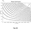
- FIG. 5C illustrates a portion of an exemplary efficiency map with power level curves according to one implementation of the present application.
- power level efficiency map 530c includes power level curves 536.
- a power level curve represents combinations of torques and RPMs of ICE 104 in Figure 1 at which ICE 104 in Figure 1 has same or similar power levels.
- Intelligent vehicle controller 102 in Figure 1 (or intelligent vehicle controller 202 in Figure 2 ) can store power level curves 536 in memory 228 in Figure 2 .
- Efficiency map 530c in Figure 5C shows power level curves with power levels ranging from Level 1 to Level 16. Power level values shown in Figure 5C are merely examples and are not intended to correspond to actual numerical values. In some implementations, efficiency map 530c may have power level curves with different ranges and increments. Thus, efficiency map 530c may account for running ICE 104 in Figure 1 at fixed or discrete power levels.
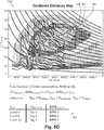
- FIG. 5D illustrates a portion of an exemplary combined efficiency map according to one implementation of the present application.
- combined efficiency map 530d includes fuel efficiency contours 532, NVH level lines 534, and power level curves 536 by combining and incorporating fuel efficiency map 530a, NVH level efficiency map 530b, and power level efficiency map 530c.
- Efficiency map 530d further includes vehicle operation points, indicated visually as squares, such as squares or vehicle operation points 582, 584, and 586, connected by dashed lines.
- Vehicle operation points of efficiency map 530d represent desirable torques and/or a desirable RPMs for ICE 104 in Figure 1 . That is, when ICE 104 in Figure 1 is run at a vehicle operation point, hybrid vehicle 100 will exhibit an acceptable NVH level and/or a desired fuel efficiency.
- the acceptable NVH level and the desired fuel efficiency of hybrid electric vehicle 100 are generally optimum values determined by intelligent vehicle controller 102 in Figure 1 (or intelligent vehicle controller 202 in Figure 2 ).
- Intelligent vehicle controller 102 in Figure 1 (or intelligent vehicle controller 202 in Figure 2 ) constrains the cost function to the desirable power level or the desirable range of power levels, as discussed above, as in Equation (3) below: f Fuel consumption NVH level subject to : P ICE ⁇ P GenMax , P ICE ⁇ P HVBusMax , P ICE ⁇ P VehSpd
- the desirable torque and the desirable RPM for ICE 104 in Figure 1 represent a torque and RPM for which hybrid electric vehicle 100 is optimized in terms of both fuel efficiency and NVH level (for example, where hybrid electric vehicle 100 has the lowest balance of BSFC and noise).
- a desirable torque and/or a desirable RPM for ICE 104 in Figure 1 may correspond to an acceptable NVH level and/or a desired fuel efficiency of hybrid electric vehicle 100 in another manner.
- intelligent vehicle controller 102 in Figure 1 (or intelligent vehicle controller 202 in Figure 2 ) may determine that an acceptable NVH level and a desired fuel efficiency of hybrid electric vehicle 100 correspond to an intersection of a NVH level line with the lowest noise along a given power level curve, so long as that intersection is within the three best fuel efficiency contours (for example, BSFC 1, BSFC 2, and BSFC 3 in Figure 5A ) along that power level curve.
- the desirable torque and the desirable RPM for ICE 104 in Figure 1 represent a torque and RPM for which hybrid electric vehicle 100 is optimized in terms of both fuel efficiency and NVH level, with lenience for fuel efficiency.
- intelligent vehicle controller 102 in Figure 1 (or intelligent vehicle controller 202 in Figure 2 ) can assign different weighting factors to fuel efficiency contours 532 and NVH level lines 534.
- table 550 shows exemplary desirable torques and the desirable RPMs for ICE 104 in Figure 1 .
- Values of P ICE , Trq desirable , and RPM desirable shown in Figure 5D are merely examples and are not intended to correspond to actual numerical values.
- a desirable torque and a desirable RPM corresponding to Level 4 is shown by the corresponding row in table 550 by table entries Trq 3 and RPM 4.
- a desirable torque and a desirable RPM corresponding to Level 6 is shown by the corresponding row in table 550 by table entries Trq 4 and RPM 4.
- a desirable torque and a desirable RPM corresponding to Level 12 is shown by the corresponding row in table 550 by table entries Trq 5 and RPM 7.
- intelligent vehicle controller 102 in Figure 1 can advantageously use the desirable torque and/or the desirable RPM to influence operation of hybrid electric vehicle 100.
- intelligent vehicle controller 102 in Figure 1 can generate a control signal for ICE controller 105 in Figure 1 (or ICE controller 205 in Figure 2 ) based on the desirable torque and/or the desirable RPM, and ICE controller 105 in Figure 1 (or ICE controller 205 in Figure 2 ) can use the control signal to run ICE 104 in Figure 1 at the desirable torque and/or the desirable RPM.
- intelligent vehicle controller 102 in Figure 1 can generate a control signal for variable exhaust valve 120 in Figure 1 (or variable exhaust valve 220 in Figure 2 ) based on the desirable torque and/or the desirable RPM, and variable exhaust valve 120 in Figure 1 (or variable exhaust valve 220 in Figure 2 ) can use the control signal to alter exhaust flow and to change sound characteristics of hybrid electric vehicle 100.
- combined efficiency map 530d includes predetermined vehicle operation points, such as vehicle operation points 582, 584, and 586, for each possible desirable power level for ICE 104 in Figure 1 .
- intelligent vehicle controller 102 in Figure 1 (or intelligent vehicle controller 202 in Figure 2 ) need not compute a desirable torque and/or a desirable RPM each time the desirable power level shifts. Processing power and processing time can be reduced.
- ICE 104 in Figure 1 can adapt to a desirable torque and/or a desirable RPM faster.
- intelligent vehicle controller 102 in Figure 1 (or intelligent vehicle controller 202 in Figure 2 ) can use adjacent power level curves and corresponding adjacent vehicle operation points of combined efficiency map 530d to interpolate another acceptable vehicle operation point.
- intelligent vehicle controller 102 in Figure 1 can adapt ICE 104 in Figure 1 to run at desirable operating torques and RPMs in accordance with power level and driving demands.
- efficiency map 530d includes both fuel efficiency contours and NVH level lines
- intelligent vehicle controller 102 in Figure 1 (or intelligent vehicle controller 202 in Figure 2 ) accommodates intelligently managing ICE 104 in Figure 1 so as to balance ICE power level shifting data and driving demands with acceptable NVH levels and desirable fuel efficiencies.
- Intelligently managing ICE 104 in Figure 1 with respect to both fuel efficiency and NVH has particular applicability for luxury hybrid electric vehicles, where convenience and comfort are both highly prioritized.
- Figures 6A and 6B each illustrate a portion of an exemplary normalized fuel efficiency and NVH level map according to one implementation of the present application.
- exemplary normalized fuel efficiency and NVH level map 630a includes normalized fuel efficiency/NVH level contours 633a.
- a normalized fuel efficiency/NVH level contour represents both fuel efficiency and NVH level.
- normalized fuel efficiency/NVH level contours 633a may represent products of fuel efficiency contours 532 in Figure 5A and NVH level lines 534 in Figure 5B after normalization.
- exemplary normalized fuel efficiency and NVH level map 630b includes normalized fuel efficiency/NVH level contours 633b, and normalized fuel efficiency/NVH level contours 633b may represent products of fuel efficiency contours 532 in Figure 5A and NVH level lines 534 in Figure 5B after normalization.
- Normalized contour values may include a product of BSFC and dB. Lower values correspond to better fuel economy and lower NVH levels of ICE 104 in Figure 1 .
- a measurement unit & map generator (not shown) can pre-produce normalized fuel efficiency/NVH level contours 633a and 633b shown in normalized fuel efficiency and NVH level maps 630a and 630b based on numerous measured values.
- Intelligent vehicle controller 102 in Figure 1 can store normalized fuel efficiency/NVH level contours 633a and 633b in memory 228 in Figure 2 .
- each normalized fuel efficiency/NVH level contour's region is shown by a unique cross-hatching in addition to being identified by a corresponding value.
- Normalized fuel efficiency and NVH level maps 630a and 630b in Figures 6A and 6B show normalized fuel efficiency/NVH level contours 633a and 633b with values of Value 1 up to Value 9. Values shown in Figures 6A and 6B are merely examples and are not intended to correspond to actual numerical values. In some implementations, Normalized fuel efficiency and NVH level maps 630a and 630b may have normalized fuel efficiency/NVH level contours 633a and 633b with different ranges and increments. The shapes of normalized fuel efficiency/NVH level contours 633a and 633b will generally vary between different vehicles and weighting factors. In one implementation, normalized contours may be adapted to normalize and include emissions measurements, in addition to both fuel efficiencies and NVH levels.
- intelligent vehicle controller 102 in Figure 1 can assign different weighting factors to fuel efficiency and NVH levels.
- intelligent vehicle controller 102 in Figure 1 assigns fuel efficiency a weighting factor of 70%, and assigns NVH level a weighting factor of 30%.
- intelligent vehicle controller 102 in Figure 1 assigns fuel efficiency a weighting factor of 30%, and assigns NVH level a weighting factor of 70%.
- each normalized fuel efficiency/NVH level contour's region is different between the implementations of Figures 6A and 6B .
- intelligent vehicle controller 102 in Figure 1 assigns weighting factors based on the selected vehicle operation mode.
- weighting factors other than 70% and 30% may be used.
- weighting factors can be assigned to emissions measurements, in addition to both fuel efficiencies and NVH levels.
- intelligent vehicle controller 102 in Figure 1 may determine different desirable torques and/or a desirable RPMs for ICE 104 in Figure 1 based on the assigned weighting factors when utilizing combined efficiency maps.
- ICE 104 can be run efficiently while allowing prioritization or leniency with respect to fuel efficiency, NVH levels, emission outputs, etc.
- FIGS 7A and 7B each illustrate a portion of an exemplary combined efficiency map according to one implementation of the present application.
- combined efficiency map 730a includes normalized fuel efficiency/NVH level contours 633a and power level curves 536 by combining and incorporating normalized fuel efficiency and NVH level map 630a and power level efficiency map 530c.
- combined efficiency map 730b includes normalized fuel efficiency/NVH level contours 633b and power level curves 536 by combining and incorporating normalized fuel efficiency and NVH level map 630b and power level efficiency map 530c.
- Efficiency maps 730a and 730b further include vehicle operation points, indicated visually as squares, such as squares or vehicle operation points 782a, 784a, and 786a, and 782b, 784b, and 786b respectively connected by dashed lines.
- Vehicle operation points of efficiency maps 730a and 730b represent desirable torques and/or a desirable RPMs for ICE 104 in Figure 1 . That is, when ICE 104 in Figure 1 is run at a vehicle operation point, hybrid vehicle 100 will exhibit an acceptable NVH level and/or a desired fuel efficiency.
- a desirable torque and a desirable RPM for ICE 104 in Figure 1 can otherwise be determined by intelligent vehicle controller 102 in Figure 1 (or intelligent vehicle controller 202 in Figure 2 ) according to any manner described above.
- intelligent vehicle controller 102 in Figure 1 may determine different desirable torques and/or a desirable RPMs for ICE 104 in Figure 1 based on the assigned weighting factors when utilizing combined efficiency maps 730a and 730b. For example, in Figure 7A , where fuel efficiency is assigned a weighting factor of 70% and NVH level is assigned a weighting factor of 30%, the first vehicle operation point along the lowest power level curve lies approximately at RPM 3 and slightly below Trq 1.
- Figure 8 illustrates a portion of an exemplary vehicle drive cycle including NVH level, ICE torque, ICE speed, ICE ON, and vehicle speed graphs according to one implementation of the present application.
- Vehicle drive cycle 844 shows graphs of vehicle speed, ICE ON command (which indicates whether the ICE is on or off), ICE speed, ICE torque, and NVH level, versus time.
- vehicle drive cycle 844 includes two traces.
- the first trace indicated visually as diamonds, represents a prior art vehicle controller using a strategy referred to as Power Following (PF).
- PF Power Following
- fuel efficiency and NVH are not both accounted for in an initial determination of torque and RPM for an ICE.
- the PF vehicle controller may create a power demand for the ICE that simply achieves a vehicle speed requested by a driver, and determine a corresponding torque and RPM for the ICE.
- the PF vehicle controller matches the instantaneous power of the ICE to the instantaneous high voltage bus demand, while not causing the battery to charge or discharge.
- the PF vehicle controller may reactively limit the power demand for the ICE, or reactively determine a new torque and/or RPM for the ICE.
- the second trace indicated visually as shaded circles, represents intelligent vehicle controller 102 in Figure 1 (or intelligent vehicle controller 202 in Figure 2 ) using a strategy referred to as Intelligent Thermostatic Control (ITC).
- ITC Intelligent Thermostatic Control
- a vehicle using a PF vehicle controller is driven similarly to hybrid electric vehicle 100 using intelligent vehicle controller 102 in Figure 1 (or intelligent vehicle controller 202 in Figure 2 ), as shown by the PF and ITC traces overlapping in the graph of vehicle speed versus time.
- the PF trace goes high at approximately time t1 in vehicle drive cycle 844, whereas the ITC trace does not go high until approximately time t2 in vehicle drive cycle 844.
- This may be attributable intelligent vehicle controller 102 in Figure 1 (or intelligent vehicle controller 202 in Figure 2 ) determining a desirable torque and/or a desirable RPM for ICE 104 in Figure 1 utilizing combined efficiency map 530d in Figure 5D so as to optimize fuel efficiency. Because ICE 104 in Figure 1 remains off longer while hybrid electric vehicle 100 accelerates from low speed, battery 110 in Figure 1 may experience larger SOC deficit, but hybrid electric vehicle 100 consumes less fuel.
- the PF traces In the ICE speed and ICE torque graphs, the PF traces generally vary more frequently than the steadier ITC traces, and the PF traces are generally higher during vehicle drive cycle 844, except that, in the ICE torque graph, the PF trace and the ITC trace are approximately equal at approximately time t5 in vehicle drive cycle 844.
- this may be attributable intelligent vehicle controller 102 in Figure 1 (or intelligent vehicle controller 202 in Figure 2 ) determining a desirable torque and/or a desirable RPM for ICE 104 in Figure 1 utilizing combined efficiency map 530d in Figure 5D so as to optimize fuel efficiency. Because the speed and torque of ICE 104 in Figure 1 are lower, hybrid electric vehicle 100 consumes less fuel.
- the PF trace is generally higher than the ITC trace at all times during vehicle drive cycle 844.
- This may be attributable intelligent vehicle controller 102 in Figure 1 (or intelligent vehicle controller 202 in Figure 2 ) determining a desirable torque and/or a desirable RPM for ICE 104 in Figure 1 utilizing combined efficiency map 530d in Figure 5D so as to minimize NVH levels of hybrid electric vehicle 100.
- ICE 104 in Figure 1 may perform less smoothly during shifts, but hybrid electric vehicle 100 experiences significantly less NVH.
- the ITC trace is generally more efficient than the PF trace, and generally exhibits lower NVH than the PF trace, under similar driving conditions, because intelligent vehicle controller 102 in Figure 1 (or intelligent vehicle controller 202 in Figure 2 ) is predictive and determines a desirable torque and/or a desirable RPM based on ICE power level shifting data utilizing a combined efficiency map.
- various implementations of the present application achieve a hybrid electric vehicle that overcomes the deficiencies in the art by determining a desirable torque and/or a desirable RPM for an ICE based on ICE power level shifting data by utilizing an efficiency map including fuel efficiency contours and NVH level lines.
Applications Claiming Priority (1)
| Application Number | Priority Date | Filing Date | Title |
|---|---|---|---|
| US15/975,587 US10730505B2 (en) | 2018-05-09 | 2018-05-09 | Hybrid electric vehicle using intelligent vehicle controller |
Publications (1)
| Publication Number | Publication Date |
|---|---|
| EP3566918A1 true EP3566918A1 (de) | 2019-11-13 |
Family
ID=66597489
Family Applications (1)
| Application Number | Title | Priority Date | Filing Date |
|---|---|---|---|
| EP19173542.2A Pending EP3566918A1 (de) | 2018-05-09 | 2019-05-09 | Hybridfahrzeug mit intelligentem fahrzeugsteuergerät |
Country Status (3)
| Country | Link |
|---|---|
| US (1) | US10730505B2 (de) |
| EP (1) | EP3566918A1 (de) |
| CN (1) | CN110466498A (de) |
Cited By (1)
| Publication number | Priority date | Publication date | Assignee | Title |
|---|---|---|---|---|
| CN111483452A (zh) * | 2020-04-13 | 2020-08-04 | 清华大学 | 混合动力系统及其控制方法 |
Families Citing this family (5)
| Publication number | Priority date | Publication date | Assignee | Title |
|---|---|---|---|---|
| JP6930445B2 (ja) * | 2018-01-30 | 2021-09-01 | トヨタ自動車株式会社 | ハイブリッド車両 |
| US10730505B2 (en) * | 2018-05-09 | 2020-08-04 | Karma Automotive Llc | Hybrid electric vehicle using intelligent vehicle controller |
| US10675984B2 (en) * | 2018-08-03 | 2020-06-09 | American Axle & Manufacturing, Inc. | Drive system and method for vehicle employing multiple electric motors |
| CN110304044B (zh) * | 2019-05-20 | 2021-08-03 | 北京理工大学 | 基于ecms的phev四驱转矩分配方法 |
| FR3130730A1 (fr) * | 2021-12-21 | 2023-06-23 | Renault | Dispositif de gestion d’un groupe motopropulseur de véhicule hybride |
Citations (3)
| Publication number | Priority date | Publication date | Assignee | Title |
|---|---|---|---|---|
| EP1347887B1 (de) * | 2000-11-23 | 2007-09-12 | Ricardo UK Limited | Verwaltung von hybridenergiequellenverteilung |
| US20160200315A1 (en) * | 2013-08-21 | 2016-07-14 | Jaguar Land Rover Limited | Hybrid Electric Vehicle Controller and Method |
| WO2017196921A1 (en) * | 2016-05-10 | 2017-11-16 | Dana Limited | Control strategies for hybrid electric powertrain configurations with a ball variator |
Family Cites Families (37)
| Publication number | Priority date | Publication date | Assignee | Title |
|---|---|---|---|---|
| JP3926514B2 (ja) * | 1999-08-17 | 2007-06-06 | 本田技研工業株式会社 | ハイブリッド車両の制御装置 |
| JP3687518B2 (ja) * | 2000-10-16 | 2005-08-24 | トヨタ自動車株式会社 | エンジン予熱始動型ハイブリッド車 |
| US6688411B2 (en) * | 2001-11-09 | 2004-02-10 | Ford Global Technologies, Llc | Hybrid electric vehicle and a method for operating a hybrid electric vehicle |
| JP3857146B2 (ja) * | 2002-01-16 | 2006-12-13 | 本田技研工業株式会社 | ハイブリッド車両の制御装置 |
| JP3587254B2 (ja) * | 2002-07-08 | 2004-11-10 | トヨタ自動車株式会社 | 車両制御装置 |
| JP3934093B2 (ja) * | 2003-08-12 | 2007-06-20 | 本田技研工業株式会社 | ハイブリット車両の制御装置 |
| US7234552B2 (en) * | 2003-09-19 | 2007-06-26 | Ford Global Technologies, Llc | Method for heating a battery in a hybrid electric vehicle |
| US7200476B2 (en) * | 2003-10-14 | 2007-04-03 | General Motors Corporation | Optimal selection of input torque considering battery utilization for a hybrid electric vehicle |
| JP4596381B2 (ja) * | 2004-02-02 | 2010-12-08 | アイシン・エィ・ダブリュ株式会社 | 電動車両駆動制御装置及び電動車両駆動制御方法 |
| JP4176662B2 (ja) * | 2004-03-11 | 2008-11-05 | 本田技研工業株式会社 | ハイブリッド車両の制振方法 |
| DE102004025460A1 (de) * | 2004-05-25 | 2005-12-29 | Bayerische Motoren Werke Ag | Verfahren zum Betreiben eines Hybridkraftfahrzeugs |
| JP2007064209A (ja) * | 2005-08-05 | 2007-03-15 | Fujitsu Ten Ltd | エンジン制御装置、制御方法、及び制御システム |
| US7377250B1 (en) * | 2006-12-27 | 2008-05-27 | Caterpillar Inc. | System and method for balancing an engine during cylinder cutout |
| US8025034B2 (en) * | 2007-01-05 | 2011-09-27 | Ford Global Technologies, Llc | Interval phasing for valve timing |
| EP2212148B1 (de) * | 2007-10-26 | 2021-04-28 | Volvo Lastvagnar AB | Verfahren zur effizienteren verwendung eines verbrennungsmotors in einem mit einer automatikstufengetriebe ausgestatteten fahrzeug |
| US7621257B1 (en) * | 2008-05-01 | 2009-11-24 | Ford Global Technologies, Llc | Engine valve operation |
| WO2010130284A1 (en) * | 2009-05-12 | 2010-11-18 | El-Forest Ab | Energy system for a hybrid vehicle |
| JP5477030B2 (ja) * | 2009-05-22 | 2014-04-23 | 日産自動車株式会社 | 電動車両の制御装置 |
| US8249796B2 (en) * | 2010-09-08 | 2012-08-21 | Ford Global Technologies, Llc | Engine control with valve operation monitoring using camshaft position sensing |
| US8880258B2 (en) * | 2011-10-17 | 2014-11-04 | Tula Technology, Inc. | Hybrid powertrain control |
| KR101339234B1 (ko) * | 2011-12-09 | 2013-12-09 | 현대자동차 주식회사 | 댐퍼 클러치 제어 방법 |
| KR101394703B1 (ko) * | 2012-10-30 | 2014-05-15 | 현대자동차주식회사 | 하이브리드 차량의 이상진동 방지 방법 |
| US8897943B2 (en) * | 2013-03-15 | 2014-11-25 | Deere & Company | Battery electric hybrid drive for a combine harvester |
| US9562470B2 (en) * | 2013-03-15 | 2017-02-07 | Tula Technology, Inc. | Valve fault detection |
| US8731762B1 (en) * | 2013-04-24 | 2014-05-20 | GM Global Technology Operations LLC | Method and system of controlling a powertrain system to reduce turbo lag in a hybrid vehicle |
| US9073545B2 (en) * | 2013-07-25 | 2015-07-07 | GM Global Technology Operations LLC | Diesel engine steady state and transient hybrid optimization |
| WO2015058105A1 (en) * | 2013-10-18 | 2015-04-23 | Stc.Unm | Methods to introduce sub-micrometer, symmetry-breaking surface corrugation to silicon substrates to increase light trapping |
| CA2996844A1 (en) * | 2014-08-29 | 2016-06-16 | Tzunum, Inc. | Power train for a hybrid-electric aircraft |
| US10578037B2 (en) * | 2015-01-12 | 2020-03-03 | Tula Technology, Inc. | Adaptive torque mitigation by micro-hybrid system |
| US10344692B2 (en) * | 2015-01-12 | 2019-07-09 | Tula Technology, Inc. | Adaptive torque mitigation by micro-hybrid system |
| KR102408785B1 (ko) * | 2015-01-12 | 2022-06-14 | 툴라 테크놀로지, 인크. | 스킵 파이어 엔진 제어 시스템에서의 소음, 진동 및 잡소리 감소 |
| JP6477088B2 (ja) * | 2015-03-20 | 2019-03-06 | いすゞ自動車株式会社 | NOx吸蔵量推定装置 |
| US9694807B2 (en) * | 2015-04-23 | 2017-07-04 | GM Global Technology Operations LLC | Method and apparatus for controlling a powertrain system employing multiple torque generating devices |
| US9914449B2 (en) * | 2016-01-13 | 2018-03-13 | Ford Global Technologies, Llc | Methods and system for improving efficiency of a hybrid vehicle |
| US10900499B2 (en) * | 2017-02-06 | 2021-01-26 | Ford Global Technologies, Llc | Cooling fans for engine cooling system |
| US10118605B2 (en) * | 2017-03-13 | 2018-11-06 | Ford Global Technologies, Llc | Methods and system for a hybrid vehicle |
| US10730505B2 (en) * | 2018-05-09 | 2020-08-04 | Karma Automotive Llc | Hybrid electric vehicle using intelligent vehicle controller |
-
2018
- 2018-05-09 US US15/975,587 patent/US10730505B2/en active Active
-
2019
- 2019-05-09 CN CN201910382305.6A patent/CN110466498A/zh active Pending
- 2019-05-09 EP EP19173542.2A patent/EP3566918A1/de active Pending
Patent Citations (3)
| Publication number | Priority date | Publication date | Assignee | Title |
|---|---|---|---|---|
| EP1347887B1 (de) * | 2000-11-23 | 2007-09-12 | Ricardo UK Limited | Verwaltung von hybridenergiequellenverteilung |
| US20160200315A1 (en) * | 2013-08-21 | 2016-07-14 | Jaguar Land Rover Limited | Hybrid Electric Vehicle Controller and Method |
| WO2017196921A1 (en) * | 2016-05-10 | 2017-11-16 | Dana Limited | Control strategies for hybrid electric powertrain configurations with a ball variator |
Cited By (2)
| Publication number | Priority date | Publication date | Assignee | Title |
|---|---|---|---|---|
| CN111483452A (zh) * | 2020-04-13 | 2020-08-04 | 清华大学 | 混合动力系统及其控制方法 |
| CN111483452B (zh) * | 2020-04-13 | 2021-06-04 | 清华大学 | 混合动力系统及其控制方法 |
Also Published As
| Publication number | Publication date |
|---|---|
| US10730505B2 (en) | 2020-08-04 |
| CN110466498A (zh) | 2019-11-19 |
| US20190344776A1 (en) | 2019-11-14 |
Similar Documents
| Publication | Publication Date | Title |
|---|---|---|
| EP3566918A1 (de) | Hybridfahrzeug mit intelligentem fahrzeugsteuergerät | |
| US10081350B2 (en) | Vehicle propulsion system having an energy storage system and optimized method of controlling operation thereof | |
| CN111434519B (zh) | 用于多组电驱动机动车辆的电池组平衡系统和控制逻辑 | |
| US10214196B2 (en) | Hybrid vehicle | |
| US9889752B2 (en) | Vehicle propulsion system having an energy storage system and optimized method of controlling operation thereof | |
| US7797089B2 (en) | System and method for managing a power source in a vehicle | |
| US8229615B2 (en) | Vehicle drive power generation control apparatus | |
| KR101836693B1 (ko) | 하이브리드 차량의 구동 토크 인터벤션 제어 장치 및 그 제어방법 | |
| US20090277701A1 (en) | Hybrid vehicle and travel control method of hybrid vehicle | |
| US20050077877A1 (en) | Managing service life of a battery | |
| US20090306843A1 (en) | Hybrid vehicle and control method thereof | |
| US6625525B2 (en) | Vehicle drive system and controlling method thereof | |
| JP7226296B2 (ja) | 車両、車両制御システム | |
| JP2006094691A (ja) | 動力出力装置およびこれを搭載する自動車並びに動力出力装置の制御方法 | |
| JP2009126258A (ja) | 車両およびその制御方法 | |
| US20170113677A1 (en) | Hybrid vehicle and control method for same | |
| US7308958B2 (en) | Method for controlling a series hybrid electric vehicle | |
| JP6122958B2 (ja) | 発電制御装置及び発電制御方法 | |
| JP4158615B2 (ja) | 車両用電源装置 | |
| JP4349466B2 (ja) | 動力出力装置およびこれを搭載する自動車並びに動力出力装置の制御方法 | |
| Skugor et al. | On smoothing HEV/EREV supervisory control action using an extended ECMS approach | |
| JP7478647B2 (ja) | ハイブリッド車両の制御方法及びハイブリッド車両の制御装置 | |
| JP4285475B2 (ja) | 動力出力装置およびこれを搭載する車両並びに動力出力装置の制御方法 | |
| JP2021084453A (ja) | ハイブリッド自動車 | |
| JP2020184857A (ja) | 車両制御装置 |
Legal Events
| Date | Code | Title | Description |
|---|---|---|---|
| PUAI | Public reference made under article 153(3) epc to a published international application that has entered the european phase |
Free format text: ORIGINAL CODE: 0009012 |
|
| STAA | Information on the status of an ep patent application or granted ep patent |
Free format text: STATUS: THE APPLICATION HAS BEEN PUBLISHED |
|
| AK | Designated contracting states |
Kind code of ref document: A1 Designated state(s): AL AT BE BG CH CY CZ DE DK EE ES FI FR GB GR HR HU IE IS IT LI LT LU LV MC MK MT NL NO PL PT RO RS SE SI SK SM TR |
|
| AX | Request for extension of the european patent |
Extension state: BA ME |
|
| STAA | Information on the status of an ep patent application or granted ep patent |
Free format text: STATUS: REQUEST FOR EXAMINATION WAS MADE |
|
| 17P | Request for examination filed |
Effective date: 20200519 |
|
| RBV | Designated contracting states (corrected) |
Designated state(s): AL AT BE BG CH CY CZ DE DK EE ES FI FR GB GR HR HU IE IS IT LI LT LU LV MC MK MT NL NO PL PT RO RS SE SI SK SM TR |
|
| STAA | Information on the status of an ep patent application or granted ep patent |
Free format text: STATUS: EXAMINATION IS IN PROGRESS |
|
| 17Q | First examination report despatched |
Effective date: 20221115 |
|
| P01 | Opt-out of the competence of the unified patent court (upc) registered |
Effective date: 20230525 |