EP3566633A1 - Waschmittelspender für haushaltswaschmaschinen, insbesondere geschirrspülmaschinen - Google Patents
Waschmittelspender für haushaltswaschmaschinen, insbesondere geschirrspülmaschinen Download PDFInfo
- Publication number
- EP3566633A1 EP3566633A1 EP19181672.7A EP19181672A EP3566633A1 EP 3566633 A1 EP3566633 A1 EP 3566633A1 EP 19181672 A EP19181672 A EP 19181672A EP 3566633 A1 EP3566633 A1 EP 3566633A1
- Authority
- EP
- European Patent Office
- Prior art keywords
- wall
- dispenser
- door
- door body
- seat
- Prior art date
- Legal status (The legal status is an assumption and is not a legal conclusion. Google has not performed a legal analysis and makes no representation as to the accuracy of the status listed.)
- Pending
Links
Images


Classifications
-
- A—HUMAN NECESSITIES
- A47—FURNITURE; DOMESTIC ARTICLES OR APPLIANCES; COFFEE MILLS; SPICE MILLS; SUCTION CLEANERS IN GENERAL
- A47L—DOMESTIC WASHING OR CLEANING; SUCTION CLEANERS IN GENERAL
- A47L15/00—Washing or rinsing machines for crockery or tableware
- A47L15/42—Details
- A47L15/44—Devices for adding cleaning agents; Devices for dispensing cleaning agents, rinsing aids or deodorants
- A47L15/4409—Devices for adding cleaning agents; Devices for dispensing cleaning agents, rinsing aids or deodorants by tipping containers or opening their lids, e.g. with the help of a programmer
Definitions
- the present invention relates to washing agent dispensers for household washing machines, in particular dishwashers, and has been developed with particular reference to dispensers provided with at least one sliding hatch or door.
- Some household washing machines, and in particular dishwashers, are equipped with a device for dispensing washing products that is configured for dispensing at least one washing agent.
- these devices are provided for dispensing, at different moments of one and the same dish-washing cycle, two different washing agents, typically represented by a detergent in the solid form (powder or tablets) and by a liquid rinsing additive.
- dispensers provided for the purposes of dispensing just one washing substance in the solid form or else in the liquid form.
- dispensers for dishwashers comprise a main body obtained by moulding of thermoplastic material, associated to one of the vertical walls that delimit the washtub of the machine (including the internal shell of the front door of the machine that faces the inside of the washtub), which is usually at least partially set in, in a fluid-tight way, in an opening provided in the wall.
- a receptacle for containing a washing agent usually a detergent in powder or tablet form, necessary for carrying out a washing cycle.
- the receptacle is provided with a closing door, which also has a respective body made of plastic material.
- the body of the door is slidably constrained to the body of the dispenser so that it can slide between a closed position and an open position in a substantially linear way or else following a path that is at least in part inclined or curved: for this purpose, corresponding slide guides are provided interacting between the body of the dispenser and the body of the door.
- Devices of this sort are known, for example, from US5884821 A and DE102005004098 A .
- US8499773 B discloses a washing agent dispenser for a dishwasher in which the door body has a first portion hinged to the dispenser body about a first axis parallel to a mouth of the receptacle for containing the washing agent, and translatable along guides provided in the dispenser body; a second portion of the door body is connected to a crank element by hinging about a second axis parallel to the first axis, the crank element being, in turn, hinged to the dispenser body about a third, fixed axis, which is parallel to the first and second axes.
- a known solution substantially of the type described in DE102005004098 A is exemplified schematically in Figures 1 to 6 , where the dispenser is designated as a whole by 1 and where the bodies of the door and of the dispenser are designated by 2 and 3, respectively.
- the body 2 of the door has two opposite lateral portions or walls, constituted by walls 2a and 2b that are generally parallel to one another and to the sliding direction of the door, indicated schematically by the arrow D of Figure 1 (in the prior document cited, the movement of the door follows a generally arched path).
- the body 3 of the dispenser has two corresponding opposite lateral portions or walls 3a and 3b, which are generally parallel to one another and to the aforesaid walls 2a and 2b of the body 2 of the door, where the outer side of each of the walls 2a and 2b faces the inner side of a corresponding wall 3a and 3b.
- two projecting elements 4 or studs Provided at the outer side of each of the walls 2a and 2b are two projecting elements 4 or studs, set at a distance from one another in the sliding direction D, which are also defined hereinafter for simplicity as "pins".
- a first pin 4 is located on the respective side wall 2a or 2b in the proximity of an end thereof, i.e., near a transverse wall 2c of the door 2, whereas the other pin 4 is located in an intermediate area of the respective side wall 2a or 2b.
- Each pin 4 is slidably engaged in a respective guide groove 5 defined on the inner side of the corresponding wall 3a or 3b, where the two guide grooves 5 of each wall 3a or 3b are arranged substantially one after another in the sliding direction D.
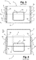
- FIG 2 designated moreover by 6 is a receptacle for containing an amount of washing agent, for example, a detergent in powder or tablet form, the mouth of which is delimited by a projecting annular lip 6a, on which a gasket, designated by 7 in Figures 3-4 , associated to the body of the door 2, is designed to operate in a fluid-tight way.
- a gasket designated by 7 in Figures 3-4 , associated to the body of the door 2
- the dispenser 1 further comprises a system for blocking/release of the door 2 (not shown).
- Dispensers according to the prior art described in general present a low stability of the door 2 in the position where the receptacle for the washing agent is closed in a fluid-tight way, in particular on account of the fact that the distance between the pins 4 on each side of the door is relatively small. This distance is basically dictated by the length of the corresponding grooves 5, which in turn depends upon the dimensions of the body 3 of the dispenser.
- this limited opening of the door determines a reduced exposure of the receptacle to the jets of washing water, so that it is difficult for the jets of washing water to carry away the washing agent when it is in powder form and flush clean the receptacle.
- the resulting residue tends to stick to the receptacle and to the door, subsequently solidifying, with consequent risk of blocking of the mechanism of opening/closing of the door itself.
- the known dispenser 1 is represented in the condition of closing of the corresponding hatch or door 2, whereas in Figures 4 and 6 the dispenser is represented in the condition of maximum opening of the door 2.
- the dashed line T represents by way of example the inner side of the door of the dishwasher, provided with an opening in which the body 3 of the dispenser 1 is partially set in.
- the pins 4 are located at a first end of the respective grooves 5, in particular an end defined in an initial portion of the grooves themselves that is inclined from below upwards in the direction of sliding of the door from the closed position to the open position.
- the presence of these inclined stretches of the grooves 5 basically has the function of enabling the door 2 - when withheld in the closed position by the blocking/release system - to assume a lowered position, in which the gasket 7 is pressed against the projecting lip 6a of the receptacle 6, and then enabling a slight lifting of the door 2, to allow sliding thereof towards the open position, thanks to the action of the spring 8 and after the door has been released by the blocking/release system.
- the dashed lines X 1 and X 2 highlight axes passing through the pins 4 provided on the outer side of the two walls 2a and 2b of the body of the door 2.
- the action of thrust of the gasket 7 on the lip 6a is determined by the pins 4, which constrain the body of the door to the body of the dispenser. It will be appreciated, however, from Figure 3 that the pins 4 that are located in an intermediate position on the walls 2a and 2b (axis X 2 ) do not enable the gasket 7 to exert a homogeneous thrust on the lip 6a.
- the portion of the gasket 7 that extends in the area comprised between the two axes X 1 and X 2 will be subject to a thrust greater than the one available on the portion of the gasket that extends outside this region (i.e., above the axis X 2 , as viewed Figure 3 ).
- This drawback may be inferred also from Figure 5 , even though the gasket 7 and the lip 6a are not highlighted therein.
- the known arrangement illustrated allows a relatively limited travel of the door 2 from the closed position to the open position, with the consequence that, even in the open position, the receptacle 6 is only partially open or exposed. As has been said, this can complicate dispensing of a detergent and/or its complete removal from the receptacle 6, in particular hindering dispensing or dropping into the washtub of washing agents in powder or a tablet form or in the form of packs of washing agents (such as packs of the type defined "3-in-1", "4-in-1" contained in the receptacle 6.
- US2008/295546 A discloses a top-loading laundry washing machine, having a detergent dispenser installed at a control panel, i.e., outside the machine washtub.
- WO03/053213 A discloses a dishwasher washing agent dispenser having a dispenser door which may be tipped over about a first axis, between a position of closing and a respective first position of opening of a receptacle defined in the dispenser body, so as to enable delivery of the washing agent contained therein.
- Articulation means are interconnected between the dispenser body and the door body, for enabling the latter to turn about a second axis between said position of closing and a respective second position of opening of the receptacle, so as to enable charging in the latter of the washing agent.
- the present invention is basically aimed to solve one or more of the aforesaid drawbacks of the prior art.
- an aim of the present invention is to provide a dispenser of washing agents that enables an increased travel of opening of a corresponding sliding door, in particular towards the outside of the profile delimited by the body of the dispenser.
- an aim of the present invention is to provide a dispenser of washing agents that enables proper fluid-tight closing of the corresponding door and/or an improved and distributed thrust of a gasket carried by a corresponding sliding door, with respect to the mouth of a receptacle for containing a washing agent, in particular in the case of a dispenser of washing agents with an opening of the sliding door towards the outside of the profile delimited by the body of the dispenser.
- an aim of the present invention is to provide a dispenser of washing agents distinguished by a good stability of movement and/or of fluid-tight closing of a corresponding sliding door, also in the case where the corresponding dispenser body is of relatively small dimensions, in particular in the case of a dispenser of washing agents with an opening of the sliding door towards the outside of the profile delimited by the body of the dispenser.
- an aim of the present invention is to provide a dispenser of washing agents that enables an increased stability or protection of a corresponding sliding door, when the door itself is in the open position or moves towards it.
- One or more of the above aims are achieved, according to the present invention, by a dispenser of washing agents that presents, among other things, the characteristics specified also in the claims.
- the objects of the invention are likewise achieved by a washing machine, in particular a dishwasher, including a dispenser of this sort.
- references to "an embodiment” or “one embodiment” in the framework of the present description is intended to indicate that a particular configuration, structure, or characteristic described in relation to the embodiment is comprised in at least one embodiment.
- phrases such as “in an embodiment”, “in one embodiment”, and the like that may be present in various points of this description do not necessarily refer to one and the same embodiment.
- terms indicating position such as “top”, “bottom”, “side”, “initial”, “final” and the like are understood to refer to the arrangement illustrated in a given figure and are in any case non-limiting.
- outer side when also these refer to a portion, wall, or element of a dispenser body and of a door body, are consequently understood as designating a side, a face, or a surface of that portion, wall, or element that are set facing in a direction generally opposite to the direction identified by the "inner side” of the same portion, wall, or element.
- a device for dispensing washing agents designated as a whole by 10 is a device for dispensing washing agents according to an embodiment of the present invention.
- the dispenser 10 is fixed to a wall that delimits the washtub of a dish-washing machine, in particular a wall defined by the door of the machine. It should be considered, however, that the dispenser according to the invention could also be fixed to some other part of the washing machine, preferably within a washtub, such as a dispenser fixed to a dish-rack, or else a dispenser configured as component separate from the machine, but designed to be located by the user in the respective washtub.
- the dispenser comprises a dispenser body 11, which is made at least in part of moulded plastic material, in particular a thermoplastic material.
- the dispenser body 11 comprises a front piece or part 11', designed to face or be located in a washtub, and a rear piece or part 11", preferably designed to be at least in part inserted in an opening of a wall of the tub, or fixed in some other way to a wall or other part of the machine, such as a dish-rack.
- the dashed line T indicates by way of example the inner side of the door of a dishwasher, provided with an opening in which the body 3 of the dispenser 1 is partially set in; it may, however, possibly indicate a wall of a dish-rack.
- the parts 11' and 11" are conveniently obtained by moulding of thermoplastic material separately from one another and then joined together, for example, via welding.
- the dispenser 10 may in any case have parts 11', 11" obtained and shaped differently.
- generic reference will be made to the dispenser body 11, taking for granted that the characteristics that pertain to the present invention basically refer to its front part 11', which defines an upper face of the dispenser, associated to which is at least one sliding hatch or door.
- a receptacle 12 in an area of the body of the dispenser 10, here including a wall 11a of the upper face of the body itself, preferably but not necessarily a substantially plane wall, a receptacle 12 is defined designed to contain a washing agent, such as a solid washing agent in the form of powder or of tablet (even though not excluded are washing substances in some other form, such as liquid or gel).
- a washing agent such as a solid washing agent in the form of powder or of tablet (even though not excluded are washing substances in some other form, such as liquid or gel).
- the mouth of the receptacle 12 is preferably surrounded by a projecting edge or lip 12a, which here rises from the wall 11a.
- Constrained in the area A to the body 11 is a hatch or door, designated as a whole by 20 and comprising a door body 21, formed via moulding of thermoplastic material, which may be like the material constituting the dispenser body 11, for example, a polypropylene added with reinforcing material, such as talcum or glass fibre.
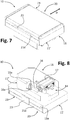
- the door 20 is movable or slidable in a guided way on the body 11 so as to be displaceable between a position of closing and a position of opening of the receptacle 12, as illustrated in Figures 7 and 18 , respectively.
- the door body 21 is constrained with respect to the dispenser body 11 via suitable slide guides.
- the dispenser 10 is devised for dispensing just the washing agent contained of the receptacle 12, but in other embodiments (not represented) the dispenser includes a further arrangement for dosage and/or dispensing of at least one further washing agent, for example, a liquid rinse aid.
- the body of the dispenser may have lateral dimensions larger than what is represented and have, in a lateral area not covered by the door 20, the inlet of a reservoir of a second washing agent, such as a liquid agent, for example, a lustering agent, with a corresponding outlet opening forming part of a corresponding dispensing system.
- the door body 21 is urged towards the respective condition of opening of the receptacle 12 via elastic means, comprising, for example, a spring.
- a spring of this sort is, for instance, designated by 13 only in Figures 9 and 10 , the ends of which are constrained between the body 11 and the body 21, possibly also via other interposed elements, for example, constrained via a coupling, or an engagement element, or a deformation of the thermoplastic material that forms the body.
- a system 14 may include, for example, an engagement element 15 in the area A, fixed to the first end of a spindle 15a that passes through the body 11.
- a lever 16 Fixed to the second end of the spindle 15a, at the back of the body 11, is a lever 16, which is subject to the reaction of a corresponding spring 16a.
- the lever 16 can be displaced by an electric actuator 17, for example, a thermal or solenoid actuator, in such a way as to cause rotation of the spindle 15a and, hence, of the engagement element 15, which releases a corresponding engagement element (not represented) provided on an inner side of the door 20.
- an electric actuator 17 for example, a thermal or solenoid actuator
- the area A in which the receptacle 12 is defined and in which the door 20 moves is delimited laterally by portions of the body 11 that rise from a general plane, here substantially identified by the wall 11a. More in general, this area A is delimited laterally by two portions or walls that are generally opposite or set at a distance apart, designated by 11b and 11c, which are preferably substantially parallel to one another and to the direction of sliding of the door, indicated by the arrow D in Figure 7 .
- the opposite portions 11b and 11c here defined as “walls” may comprise, for example, at least two portions of the body 11, which are in relief with respect to the plane of the area A or to the plane of the mouth part of the receptacle 12 and are located substantially in the proximity of the two opposite sides of the door 20.
- the walls 11b is 11c are walls in relief, substantially at the lateral ends of the body 11.
- the walls 11b and 11c are preferably integrated in the body 11, even though they may be associated thereto in some other way, such as welding or gluing, or by engagement.
- At least one of the walls 11b and 11c, or an additional wall may be an intermediate wall in relief, for example, a wall of separation between the area A and the area in which the aforementioned mouth of a reservoir of a second liquid washing agent is located.
- the door body 21 has a main wall 21a, the inner side of which generally faces the wall 11a of the body 11, as well as a series of side walls, which in the example extend from the wall 21a towards the wall 11a. More in general, the door body 21 has at least two sides or side walls, designated by 21b and 21c, which are preferably generally parallel to one another and to the direction D of sliding of the door 20, and hence preferably substantially parallel to the walls 11b and 11c of the body 11. These walls 21b and 21c are preferably integrated in the door body 21, even though they may be associated thereto in some other way, such as welding or gluing, or by engagement.
- annular gasket 40 mounted in a region of the lower face of the door body 21 (corresponding to the inner side of its wall 21a) that is comprised between the walls 21b and 21c is a annular gasket 40, preferably having a substantially quadrangular development or, more in general, a development similar to that of the projecting edge or lip 12a of the receptacle 12.
- the gasket 40 is preferably mounted in a respective housing or seat 41 defined on the inner side of the wall 21a.
- FIG. 9-12 Visible in different views in Figures 9-12 are the various portions of the body 11 and of the body 21 that are of specific interest for the purposes of possible embodiments of the invention, represented at least by the walls 11b and 11c of the dispenser body 11 and the walls 21b and 21c of the door body 21.
- Figure 9 Clearly visible in Figure 9 are the inner side of the wall 11c and the outer side of the wall 21b, whereas clearly visible in Figure 10 are the outer side of the wall 21c and part of the inner side of the wall 11b.
- slide guides Operative between the walls 11b and 21b, on one side, and the walls 11c and 21c, on the other side, are slide guides, which constrain the door body 21 with respect to the dispenser body 11.
- These slide guides comprise guide elements and guided elements, at the mutually facing sides of the walls 11b and 21b and the mutually facing sides of the walls 11c and 21c.
- the aforesaid facing sides are the inner sides of the walls 11b and 11c and the outer sides of the walls 21b and 21c, respectively, but this does not constitute an essential characteristic of the invention.
- the aforesaid facing sides could be the outer sides of the walls 11b and 11c and the inner sides of the walls 21b, 21c, respectively.
- one slide guide could be provided between the inner side of the wall 11b and the outer side of the wall 21b, whereas the opposite slide guide could be provided between the outer side of the wall 11c and the inner side of the wall 21c (or vice versa).
- the walls of the dispenser body in which the slide guides for the door are in part provided are not necessarily walls generally opposite and/or parallel to one another.
- these guide walls could lie substantially in one and the same plane (consider a substantially flat door, with the respective guide parts defined on the inner or lower side of the door), or else be arranged angled with respect to one another (for example, with one guide wall substantially vertical and the other guide wall substantially horizontal).
- the corresponding walls of the door body in which the respective parts of the slide guides are defined do not necessarily have to be opposite and/or parallel to one another.
- the guide elements comprise at least one seat 30a and at least one projecting element 31a, both defined in the side of the respective first wall 11b or 11c that faces the corresponding side of the corresponding second wall 21b or 21c of the door body 21.
- the guided elements comprise at least one second projecting element 30b and one second seat 31b, both defined in the side of the respective wall 21b or 21c that faces the corresponding side of the corresponding wall 11b or 11c of the dispenser body 11.
- Each projecting element 31a of the first walls 11b, 11c is engaged in a respective seat 31b of the second walls 21b, 21c, whereas each projecting element 30b of the second walls 21b, 21c is engaged in a respective seat 30a of the first walls 11c, 11c.
- the seats 30a and 31b extend longitudinally, in particular in the form of grooves or similar recessed elements, but not excluded from the scope of the invention is the case of seats defined by parts in relief with respect to the side of interest of the corresponding wall of the body 11 or of the body 21, for example, in the form of rails.
- the projecting elements 30b and 31a comprise sliding elements in relief, for example, in the form of pins or studs.
- the length of the seats 30a and 31b may be increased as compared to the prior art, as likewise the distance between the projecting elements 30b and 31a, on each side of the door 20.
- the fact that one projecting element 30b is provided on the door 20 and the other projecting element 31a on the dispenser body 11 enables exploitation of the entire length of the seats 30a and 31b, respectively on the body 11 and the door 20, likewise increasing the travel of the latter.
- the projecting elements 30b, 31a are configured substantially as studs or pins projecting from the corresponding wall, preferably cylindrical pins or, more in general, pins designed to enable prevalently sliding, albeit also allowing possible angular movements.
- the elements 30b, 31a will also be defined as “pins”, and specifically also as “guide pins” with reference to the pins 31a, and “guided pins” with reference to the pins 30b.
- the seats 30a here represented by way of example in the form of grooves, will also be defined as “guide grooves” and the elements 31b as “guided grooves”, where the term “groove” is not, however, intended to limit the invention to the case of recessed seats, as already mentioned above.
- guide pins and “guide grooves” are meant elements that are located in a fixed position or are fixed with respect to the body 11 of the dispenser 10, whereas by the terms “guided pins” and “guided grooves” are meant elements located in a position movable with respect to the body 11 of the dispenser 10 and/or elements that are located in a fixed position or are fixed with respect to the body 21 of the door 20.
- the grooves 30a, 31b and the pins 30b and 31a are defined integrally by the bodies 11 and 20 following upon moulding of these bodies with thermoplastic material.
- the grooves 30a and the pins 31a are defined on the corresponding walls 11b and 11c, whereas the grooves 31b and the pins 30b are defined on the corresponding walls 21b and 21c.
- each guide pin 31a of the dispenser body 11 is engaged in a corresponding guided groove 31b of the door body 21, whereas each guided pin 30b of the door body 21 is engaged in a corresponding guide groove 30a of the dispenser body 11.
- the grooves 30a and 31b have the same development in length, but this does not constitute an essential characteristic (see, for example, the case of the embodiment of Figure 20 ).
- each of the guide grooves 30a of the dispenser body 11 and each of the guided grooves 31b of the door body 21 have an initial end region and a final end region, which can be engaged by the corresponding pins 30b and 31a when the door 20 is in the position of closing (as, for example, in Figures 11-12 ) and position of opening (as, for example, in Figures 16-18 ), respectively.
- the guide pins 31a are each set at a distance from the distal end of the corresponding guide groove 30a, whereas the proximal ends of the guided grooves 31b are each set at a distance from the corresponding guided pin 30b.
- the slide guides, and more in particular the grooves 30a and 31b, are preferably configured in such a way that the gasket 40 comes into contact with the sealing lip 12a of the receptacle 12 only in a final stage of the displacement of the door 20 from the open position to the closed position, which is usually performed manually by a user after loading of a washing agent into the receptacle itself.
- a proximal end region of each guide groove 30a has a groove portion, which extends at a level lower than that of the guide pin 31a (taking as reference a plane or wall of the door or of the dispenser, such as the main wall 21a or the area A, and/or a horizontal position of the dispenser, as, for example, in Figures 13-14 ).
- each guided groove 31b has a groove portion that extends at a level higher than the guided pin 30b (once again with reference to a plane or wall of the door or of the dispenser, such as the main wall 21a or the area A, and/or a horizontal position of the dispenser, as in Figures 13-14 ): this feature may in particular be appreciated from Figures 13 and 14 , where the aforesaid proximal and distal end portions are designated by 30a' and 31b', respectively.
- the groove portions 30a' and 31b', the proximal one and the distal one respectively hence extend at a level different from the level at which a remaining main portion 30a" and 31b" of the respective groove 30a or 31a extends, here a substantially linear or rectilinear main portion.
- the portion 30a' of each guide groove 30a is an initial portion, which extends at a height or level lower than that of the remaining main portion 30a".
- the groove portions 30a' are preferably inclined downwards so that each constitutes a sort of step that is engaged by the corresponding guided pin 30b during the final phase of sliding of the door 20 towards the closed position.
- each guided groove 31b is a final portion, which extends at a height or level higher than that of the remaining main portion 31b".
- the groove portions 31b' are preferably inclined upwards, to constitute each a sort of step that is engaged by the corresponding guide pin 31a during the final phase of sliding of the door 20 towards the closed position.
- a portion of the guide grooves 30a substantially faces a portion of the guided grooves 31b.
- a partial overlapping of the grooves 30a and 31b may be appreciated from Figure 13 , in which there may be noted a partial overlapping of the grooves 30a and 31b.
- the figure in question represents the case of prevalently rectilinear grooves 30a and 31b with an (initial or final) inclined end portion, but the grooves may have at least in part facing portions even it they have a different shape, as, for example, in the embodiments of Figures 19 and 20 described hereinafter.
- the proximal or initial ends of the guide grooves 30a are each located in an end region of the corresponding side (here the inner side) of the wall 11c or 11b, whereas the guide pins 31a are each located in the opposite end region of the same side of the wall 11b or 11c.
- the guided pins 30b are each located in an end region of the corresponding side (here the outer side) of the respective wall 21b or 21c, whereas the final or distal ends of the guided grooves 31b are each located in the opposite end region of the same side of the wall 21b or 21c.
- the gasket 40 is mounted in a region of the lower face of the wall 21a of the body 21, which - with reference to the longitudinal direction of the walls 21b and 21c - is located in an intermediate position between the guided pins 30b and the final ends of the guided grooves 31b.
- This feature may be inferred, for example, from Figure 10 , where designated as a whole by R is the region of the door that is comprised between the two parallel axes represented dashed, which pass between the pins 30b and between the final ends of the grooves 31b, respectively.
- this characteristic contributes to guaranteeing a homogeneous and distributed thrust of the gasket 40 with respect to the projecting lip 12a of the receptacle 12.
- This inventive characteristic is present also in the case of other possible sealing configurations, such as the case not represented of a second gasket instead of the lip 12a, or else of a gasket 40 mounted on the body 11 and a lip 12a fixed with respect to the door 20.
- Figure 13 illustrates a condition where the door 20 is closed, with the pins 30b and 31a that engage the initial and final end regions, respectively, of the grooves 30a and 31b.
- the door 20 then proceeds in its opening movement, with the guided pins 30b that follow the main portion 30a" of the respective guide grooves 30a, and with the main portion 31b" of the guided grooves 31b that slides on the respective guide pins 31a as far as the end-of-travel position, determined, for example, by the spring 13 or by the mechanical interference between the pins and the final end of the corresponding grooves (or by a possible other end-of-travel damping element, for example, of an elastic or elastomeric type, associated to the door 20 and/or to the dispenser body 11).
- one guide groove 30a and one guide pin 31a are defined on each wall 11b and 11c of the body 11 and, conversely, one guided pin 30b and one guided groove 31b are defined on each wall 21b and 21c of the body 21 enables, in the open position of the door 20, the guided pins 30b to be very close to the guide pins 31a, thereby affording a greater travel of the door.
- This inventive solution in particular with pins that are movable and can be brought closer to one another, also enables a smaller distance to be obtained between the pins as compared to known solutions, where the pins are at a predefined fixed distance from one another.
- the extent of this travel may of course be determined in the design stage and is a function of the length of the grooves 30a, 31b and of the distance of the pins 31a and 30b from the final end and the initial end, respectively, of the grooves 30a and 31a.
- the fact that for each side of the door one guide groove is located on the body 11 and one guided groove is located on the body 21 enables increase of the length between the grooves themselves, and hence a greater distance between the corresponding pins 30b and 31a, with a consequently high stability of movement of the door, even though the travel allowed is increased as compared to the prior art.
- the mutual position between the projecting elements, for example, in the form of pins, and the mutual position of the seats, for example, in the form of grooves, varies during movement of the sliding door.
- the door body 21 has an end portion or wall, the lower profile of which defines a recess, so that the aforesaid wall does not interfere with the sealing lip 12a of the receptacle 12 during the displacements of the door 20.
- This portion or wall may be defined as "rear”, as viewed from the direction of displacement (D 1 , Figures 9 and 10 ) of the door 20 from the closed position to the open position.
- This feature enables reduction of the extent of the displacements upwards and downwards of the door 20, in the course of its passage between the open and closed positions, i.e., reduction of the length of the initial and final inclined portions of the grooves 30a and 31b, respectively, and then, in the final analysis, reduction of the height both of the side walls 11b, 11c of the body 11 and of the side walls 21b and 21c of the body 21, to the advantage of compactness of the dispenser 10.
- the rear transverse wall of the body 21 is designated by 21d in the figures and is in particular the transverse wall closer to the guided pins 30a, which extends substantially between the side walls 21b and 21c and is substantially orthogonal to the wall 21a, associated to which is the gasket 40.
- the aforesaid recess is instead designated by 22 and is substantially in a central position of the lower profile of the wall 21d or, in any case, in a position aligned to the lip 12a of the receptacle 12.
- the recess 22 could also extend substantially throughout the width of the wall 21d.
- the door body 21 defines, or has associated, at least one supporting element that projects downwards, i.e., towards the wall of the machine on which the dispenser 10 is fixed and has a lateral surface facing a corresponding end wall or portion of the dispenser body.
- the aforesaid supporting element is associated or defined at an end portion or wall of the door body, it, however, being possible for it to be associated at least in part to the dispenser body 11 or defined by the latter.
- the aforesaid portions or walls of the door body and of the dispenser body may be defined as "front", as viewed from the direction of displacement (D 1 , Figures 9 and 10 ) of the door 20 from the closed position to the open position.
- the aforesaid supporting element has the function of preventing any risk of damage to the door 20 or to its guide system, when the door is in the open position and a portion thereof projects substantially in cantilever fashion from the dispenser body (a condition in which the door could be occasionally urged in an anomalous way, for example, by a user or by a pan resting on the open door).
- the aforementioned front transverse wall of the body 21 is designated in the figures by 21e, whereas designated by 11e is the corresponding wall of the body 11.
- the transverse wall 21e is in particular the one closer to the final end of the guided grooves 31b, which extends substantially between the side walls 21b and 21c and is substantially orthogonal to the wall 21a, associated to which is the gasket 40.
- the aforesaid supporting element is instead designated by 23 and has a length greater than the distance between the inner side 21a of the body 11 and the wall 11a of the body 11.
- the supporting element 23 projects towards from the door, i.e., towards the wall on which the dispenser 10 is fixed, at the outer side of the wall 21e.
- the element 23 does not hinder movement of the door towards the closed position, it being possible for it to come into contact with the wall 11e of the body 11.
- the at least one supporting element 23 may be provided at the inner side of the aforesaid projecting part of the wall 21a.
- the element 23 has a substantially flattened shape, here substantially in the form of a plate so as not to increase considerably the overall dimensions of the dispenser.
- the supporting element 23 is located in a central position of the wall 21e, but this position is not to be understood as limiting in so far as, in variant embodiments, there could be provided an element 23 with a width at least equal to that of the door 20 or else two or more elements 23 distributed along the wall 21e.
- the supporting element could then comprise a number of elements in relief, which may be located in other positions, such as the two ends of the door 20, in positions corresponding to the two walls 21b and 21c, and may be provided with an elastic element for resting on the wall of the washing machine, such as a element made of elastomeric material.
- the element or elements 23 are preferably formed integrally with the door body 21, in the course of moulding of the latter, but not excluded from the invention is the case of at least one supporting element 23 configured as distinct component and applied to the door body 21.
- the function of the supporting element 23 may be readily inferred from Figure 14 , where the door 20 is open and a portion thereof projects in cantilever fashion from the dispenser body 11.
- the presence of the element 23 makes it possible to counter the amount of bending or stresses that can be exerted from above on the aforesaid projecting portion of the door 20, due, for example, to accidental impact by the user or by relatively heavy objects that drop on the door itself.
- the presence of the element 23 counters, for example, bending of the projecting part of the door, and hence the consequent stress on its guide system.
- the height of the element 23 it is preferable for the height of the element 23 to be as great as possible, compatibly with the space available in height.
- the portion of the supporting element 23 that extends downwards beyond the lower edge of the wall 21e has a length (height) slightly smaller than the height of the wall designated by 11e of the dispenser body 11, the lower edge of which is substantially in contact with the surface of the door T.
- the lower edge of the supporting element does not interfere with the side of the door T in which the body 11 is partially set in. Moreover, following upon opening of the door 20, and hence its slight raising due to the inclined portions of the grooves 30a and 31b, the distance between the lower edge of the element 23 and the corresponding side of the door T remains in any case minimal: consequently, in the case of impact on the projecting portion of the door, its bending will be very limited, with a practically absent or minimal stress on its guide system.
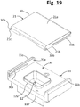
- Figures 19 and 20 illustrate possible variant embodiments of the invention, specifically in relation to the shape of the guide grooves and/or of the guided grooves, which may of course be modified according to the type of sliding desired for the door, for example, at least in part arched.
- Figure 19 illustrates the case where the guide grooves 30a and the guided grooves 31b both have a prevalent portion substantially curved or arched so as to obtain a corresponding movement of the door 20 in the course of its displacements between the open and closed positions. Also in the embodiment exemplified, the grooves have the initial or final end portions inclined, even though this may not be indispensable in the case of curved grooves.
- the shape of the guide grooves is not necessarily similar to the shape of the guided grooves. Also the development in length of the grooves on the body 11 and on the body 21 is not necessarily the same. These cases are both represented in Figure 20 , where the guided grooves 31b on the body 21 are similar to the ones illustrated with reference to Figures 7-18 , whereas the guide grooves 30a on the body 11 have a different shape, which is hence distinguished by a succession of portions or stretches inclined at different angles (which could also be replaced by a number of curved stretches, or by stretches curved in different directions, which may be associated to linear stretches, such as for example a guide with a substantially S-shaped path).
- the guide parts of the door 20 are present on a stationary body of the dispenser 10 (the body 11) and the corresponding guided parts are present on a movable body (the body 21).
- at least part of the guides may be defined in one or more mechanical connection members or elements, set between a stationary body of the dispenser and a movable body of the door, such as for example stationary elements or members fixed to the dispenser body 11 and/or to the door body 21, or else movable transmission elements or members, which are also articulated to the aforesaid stationary body and/or to the movable body, such as for example a crank element.
- dispenser body and/or "door body” present in various parts of this description and of the ensuing claims are intended to include also fixed or movable elements associated to the bodies previously designated by 11 and 21, such as the aforementioned interposed members or elements, which connect a stationary part of the dispenser and its door, for example, for constraining or guiding the movement of the door itself with respect to the aforesaid stationary part, it being possible for said interposed elements or members to be associated to the at least one body or both of the bodies 11 and 12.
- the aforesaid interposed elements or members may hence comprise guide elements and guided elements similar to the ones described previously.
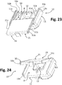
- the dispenser body 21 comprises a transmission element, designated as a whole by 50, hinged to the body 21, and slidably coupled to which is the door body 21.
- the body 51 of the transmission element 50 has an intermediate portion 51a and two side portions or walls 51b and 51c, where provided on the inner side of these portions 51b and 51c are a respective guide seat 30a and a projecting guide element 31a of the type described previously: visible in Figure 24 is only the inner side of the wall 41b.
- the intermediate portion 51a that connects the two walls 51b and 51c to one another is preferably shaped so as not to interfere with the mouth of the receptacle 12: for this purpose, in the example, the portion 51a has a recess 51a'. Preferably, the portion 51a has a thickness smaller than that of the projecting edge 12a of the receptacle 12.
- the element 50 i.e., its body 51
- the body 11 is hinged to the body 11, substantially in the area indicated by the arrows Y, in order to be moved angularly and enable a corresponding angular movement of the door 20, as emerges from Figure 24 .
- the guided sliding of the body 21 with respect to the element 50 is instead obtained according to the modalities already described previously, thanks to the slidable coupling between the guide members and the guided members.
- the inner side of the walls 11b and 11c of the body 11, on the one hand, and the outer side of the walls 41b and 41c of the element 40, on the other, may be substantially plane, obviously without considering the presence of the necessary hinging elements in the points Y, such as (see Figure 22 ) a hole 52, preferably a blind hole, on the inner sides of the walls 11b, 11c and a corresponding pin 51d projecting on the outer side of the walls 51b and 51c (or vice versa).
- the parts of the slide guides may be operative between the inner sides of the side walls of the dispenser body and the outer sides of the side walls of the door body or, vice versa, between the outer sides of the side walls of the dispenser body and the inner sides of the side walls of the door body, or again with combinations of the above arrangements, according to the teachings of the international patent application WO/2015001511 A filed in the name of the present Applicant.
- the dispenser body or the door body may comprise a fixed or movable connection element, on which respective parts of the slide guides are obtained.
- At least one of the dispenser body 11 and the door body 21 may comprise at least one constraint element, which is additional to the walls 11b and 11c and to the walls 21b and 21c, where this constraint element is prearranged for limiting displacements of the guided elements 30b, 31b with respect to the guide elements 30a, 31a in a direction generally transverse to the direction D of sliding of the door 20.
- the guide parts also defined herein as "projecting elements” could, for example, comprise rails in relief, and consequently the “seats” could comprise a pair of reliefs (defining between them a recessed part), between which the aforesaid rail slides.
- a “seat” could be defined between two rails in relief, slidably engaged by a corresponding "projecting element”.
Applications Claiming Priority (3)
| Application Number | Priority Date | Filing Date | Title |
|---|---|---|---|
| ITUB20151498 | 2015-06-18 | ||
| EP16804900.5A EP3310239B1 (de) | 2015-06-18 | 2016-06-16 | Waschmittelspender für haushaltswaschmaschinen, insbesondere geschirrspülmaschinen |
| PCT/IB2016/053575 WO2016203420A2 (en) | 2015-06-18 | 2016-06-16 | Washing agent dispenser for household washing machines, in particular dishwashers |
Related Parent Applications (2)
| Application Number | Title | Priority Date | Filing Date |
|---|---|---|---|
| EP16804900.5A Division-Into EP3310239B1 (de) | 2015-06-18 | 2016-06-16 | Waschmittelspender für haushaltswaschmaschinen, insbesondere geschirrspülmaschinen |
| EP16804900.5A Division EP3310239B1 (de) | 2015-06-18 | 2016-06-16 | Waschmittelspender für haushaltswaschmaschinen, insbesondere geschirrspülmaschinen |
Publications (1)
| Publication Number | Publication Date |
|---|---|
| EP3566633A1 true EP3566633A1 (de) | 2019-11-13 |
Family
ID=54199955
Family Applications (3)
| Application Number | Title | Priority Date | Filing Date |
|---|---|---|---|
| EP16804900.5A Active EP3310239B1 (de) | 2015-06-18 | 2016-06-16 | Waschmittelspender für haushaltswaschmaschinen, insbesondere geschirrspülmaschinen |
| EP19181672.7A Pending EP3566633A1 (de) | 2015-06-18 | 2016-06-16 | Waschmittelspender für haushaltswaschmaschinen, insbesondere geschirrspülmaschinen |
| EP21201872.5A Withdrawn EP3960062A1 (de) | 2015-06-18 | 2016-06-16 | Waschmittelspender für haushaltswaschmaschinen, insbesondere geschirrspülmaschinen |
Family Applications Before (1)
| Application Number | Title | Priority Date | Filing Date |
|---|---|---|---|
| EP16804900.5A Active EP3310239B1 (de) | 2015-06-18 | 2016-06-16 | Waschmittelspender für haushaltswaschmaschinen, insbesondere geschirrspülmaschinen |
Family Applications After (1)
| Application Number | Title | Priority Date | Filing Date |
|---|---|---|---|
| EP21201872.5A Withdrawn EP3960062A1 (de) | 2015-06-18 | 2016-06-16 | Waschmittelspender für haushaltswaschmaschinen, insbesondere geschirrspülmaschinen |
Country Status (8)
| Country | Link |
|---|---|
| US (2) | US10939798B2 (de) |
| EP (3) | EP3310239B1 (de) |
| KR (1) | KR102612670B1 (de) |
| CN (1) | CN108064144B (de) |
| DE (1) | DE202016008797U1 (de) |
| ES (1) | ES2907549T3 (de) |
| PL (1) | PL3310239T3 (de) |
| WO (1) | WO2016203420A2 (de) |
Families Citing this family (13)
| Publication number | Priority date | Publication date | Assignee | Title |
|---|---|---|---|---|
| CN207220778U (zh) * | 2017-01-24 | 2018-04-13 | 李明龙 | 一种滑盖式水槽洗碗机 |
| DE102017114784A1 (de) * | 2017-07-03 | 2019-01-03 | Sanhua Aweco Appliance Systems Gmbh | Vorrichtung zur Abgabe von Reinigungsmittel |
| DE102017114794A1 (de) * | 2017-07-03 | 2019-01-03 | Sanhua Aweco Appliance Systems Gmbh | Vorrichtung zur Abgabe von Reinigungsmittel |
| PL234975B1 (pl) * | 2017-10-09 | 2020-05-18 | Bitron Poland Spolka Z Ograniczona Odpowiedzialnoscia | Urządzenie dozujące środek myjący, w szczególności do zmywarki do naczyń |
| IT201800006469A1 (it) * | 2018-06-19 | 2019-12-19 | Dispensatore di agenti di lavaggio e metodo di montaggio | |
| KR20200000474U (ko) | 2018-08-21 | 2020-03-03 | 경수 예 | 식기세척기의 세제투입장치 |
| IT201800008272A1 (it) * | 2018-08-31 | 2018-12-01 | Elbi Int Spa | Erogatore di agenti di lavaggio per una macchina lavatrice, in particolare una macchina lavastoviglie. |
| KR20200071982A (ko) | 2018-12-12 | 2020-06-22 | 엘지전자 주식회사 | 세탁기의 세제공급기구 |
| KR102124363B1 (ko) | 2019-04-19 | 2020-06-23 | 우성알앤디 주식회사 | 식기 세척기의 세제 디스펜서 |
| CN110158281B (zh) * | 2019-05-31 | 2021-02-09 | 三花亚威科电器设备(芜湖)有限公司 | 洗涤剂分配器 |
| US20220167636A1 (en) * | 2020-12-02 | 2022-06-02 | Weber-Stephen Products Llc | Smoker boxes having slidable lids |
| KR20220117664A (ko) * | 2021-02-17 | 2022-08-24 | 엘지전자 주식회사 | 식기세척기 |
| USD1020138S1 (en) * | 2021-08-31 | 2024-03-26 | Foshan Shunde Midea Washing Appliances Manufacturing Co., Ltd. | Automatic detergent dispenser for dishwasher |
Citations (6)
| Publication number | Priority date | Publication date | Assignee | Title |
|---|---|---|---|---|
| US5884821A (en) | 1995-12-21 | 1999-03-23 | Bsh Bosch Und Siemens Hausgerate Gmbh | Device for dispensing detergent, particularly for dishwashers |
| WO2003053213A1 (en) | 2001-12-21 | 2003-07-03 | Eltek S.P.A. | A dispenser of washing agents for a household washing machine, in particular a dish-washer |
| DE102005004098A1 (de) | 2004-01-29 | 2005-08-18 | Elbi International S.P.A. | Vorrichtung zur Ausgabe von Reinigungsmittel, insbesondere für eine Geschirrspülmaschine |
| US20080295546A1 (en) | 2007-05-28 | 2008-12-04 | Cheon-Soo Cho | Top-loading type washing machine |
| US8499773B2 (en) | 2006-04-07 | 2013-08-06 | Elbi International S.P.A. | Device for dispensing a washing agent in a washing machine, particularly a dishwasher |
| WO2015001511A1 (en) | 2013-07-04 | 2015-01-08 | Eltek S.P.A. | Washing-agent dispenser for household washing machines, in particular dishwashers |
Family Cites Families (3)
| Publication number | Priority date | Publication date | Assignee | Title |
|---|---|---|---|---|
| JP2921082B2 (ja) * | 1990-10-02 | 1999-07-19 | 松下電器産業株式会社 | 食器洗い機の処理剤投入装置 |
| JP2007117137A (ja) * | 2005-10-25 | 2007-05-17 | Matsushita Electric Ind Co Ltd | ドラム式洗濯乾燥機 |
| WO2011063942A1 (de) * | 2009-11-24 | 2011-06-03 | Aweco Appliance Systems Gmbh & Co. Kg | Vorrichtung zur abgabe von reinigungsmittel |
-
2016
- 2016-06-16 CN CN201680035529.4A patent/CN108064144B/zh active Active
- 2016-06-16 US US15/736,819 patent/US10939798B2/en active Active
- 2016-06-16 WO PCT/IB2016/053575 patent/WO2016203420A2/en active Application Filing
- 2016-06-16 PL PL16804900T patent/PL3310239T3/pl unknown
- 2016-06-16 EP EP16804900.5A patent/EP3310239B1/de active Active
- 2016-06-16 EP EP19181672.7A patent/EP3566633A1/de active Pending
- 2016-06-16 KR KR1020187001149A patent/KR102612670B1/ko active IP Right Grant
- 2016-06-16 DE DE202016008797.6U patent/DE202016008797U1/de active Active
- 2016-06-16 ES ES16804900T patent/ES2907549T3/es active Active
- 2016-06-16 EP EP21201872.5A patent/EP3960062A1/de not_active Withdrawn
-
2021
- 2021-03-02 US US17/189,924 patent/US11497379B2/en active Active
Patent Citations (6)
| Publication number | Priority date | Publication date | Assignee | Title |
|---|---|---|---|---|
| US5884821A (en) | 1995-12-21 | 1999-03-23 | Bsh Bosch Und Siemens Hausgerate Gmbh | Device for dispensing detergent, particularly for dishwashers |
| WO2003053213A1 (en) | 2001-12-21 | 2003-07-03 | Eltek S.P.A. | A dispenser of washing agents for a household washing machine, in particular a dish-washer |
| DE102005004098A1 (de) | 2004-01-29 | 2005-08-18 | Elbi International S.P.A. | Vorrichtung zur Ausgabe von Reinigungsmittel, insbesondere für eine Geschirrspülmaschine |
| US8499773B2 (en) | 2006-04-07 | 2013-08-06 | Elbi International S.P.A. | Device for dispensing a washing agent in a washing machine, particularly a dishwasher |
| US20080295546A1 (en) | 2007-05-28 | 2008-12-04 | Cheon-Soo Cho | Top-loading type washing machine |
| WO2015001511A1 (en) | 2013-07-04 | 2015-01-08 | Eltek S.P.A. | Washing-agent dispenser for household washing machines, in particular dishwashers |
Also Published As
| Publication number | Publication date |
|---|---|
| US11497379B2 (en) | 2022-11-15 |
| EP3310239B1 (de) | 2021-10-13 |
| DE202016008797U1 (de) | 2019-09-30 |
| KR102612670B1 (ko) | 2023-12-11 |
| ES2907549T3 (es) | 2022-04-25 |
| EP3960062A1 (de) | 2022-03-02 |
| KR20180019659A (ko) | 2018-02-26 |
| WO2016203420A3 (en) | 2017-03-09 |
| US20210177240A1 (en) | 2021-06-17 |
| CN108064144A (zh) | 2018-05-22 |
| CN108064144B (zh) | 2020-12-01 |
| WO2016203420A2 (en) | 2016-12-22 |
| US20180360294A1 (en) | 2018-12-20 |
| EP3310239A2 (de) | 2018-04-25 |
| PL3310239T3 (pl) | 2022-05-30 |
| US10939798B2 (en) | 2021-03-09 |
Similar Documents
| Publication | Publication Date | Title |
|---|---|---|
| EP3310239B1 (de) | Waschmittelspender für haushaltswaschmaschinen, insbesondere geschirrspülmaschinen | |
| EP3016570B1 (de) | Waschmittelspender für haushaltswaschmaschinen, insbesondere geschirrspülmaschinen | |
| US7302956B2 (en) | Washing agents dispenser device for a dishwashing machine | |
| US7063092B2 (en) | Washing agent dispensing device for a household washing machine, in particular a dishwasher | |
| EP1450661B1 (de) | Dosiervorrichtung für geschirrspülmaschinen | |
| US20160296099A1 (en) | Integrated washing agent dispenser, in particular for a dishwasher | |
| US7506656B2 (en) | Dispenser of washing agents for a household washing machine, in particular a dishwasher | |
| EP1989988A1 (de) | Spendervorrichtung für ein Wasch- und/oder Spülmittel in einem Geschirrspüler mit verbessertem Mechanismus für manuelle Öffnung | |
| EP3621508B1 (de) | Waschmittelspender für haushaltsmaschinen zum waschen, insbesondere geschirrspülmaschinen | |
| KR20090120393A (ko) | 식기 세척기 | |
| CN110279380A (zh) | 分配装置和洗涤电器 | |
| WO2023238029A1 (en) | Washing agent dispenser for dishwashers | |
| ITTO20010085A1 (it) | Macchina lavastoviglie domestica con dispositivo dispensatore di agenti di lavaggio, e relativo programma di lavaggio. | |
| IT201900015746A1 (it) | Dispositivo dispensatore di agenti di lavaggio per lavastoviglie | |
| ITTO20010153A1 (it) | Macchina di lavaggio a carica dall'alto, con dispensatore di agenti di lavaggio associato allo sportello. |
Legal Events
| Date | Code | Title | Description |
|---|---|---|---|
| PUAI | Public reference made under article 153(3) epc to a published international application that has entered the european phase |
Free format text: ORIGINAL CODE: 0009012 |
|
| STAA | Information on the status of an ep patent application or granted ep patent |
Free format text: STATUS: THE APPLICATION HAS BEEN PUBLISHED |
|
| AC | Divisional application: reference to earlier application |
Ref document number: 3310239 Country of ref document: EP Kind code of ref document: P |
|
| AK | Designated contracting states |
Kind code of ref document: A1 Designated state(s): AL AT BE BG CH CY CZ DE DK EE ES FI FR GB GR HR HU IE IS IT LI LT LU LV MC MK MT NL NO PL PT RO RS SE SI SK SM TR |
|
| STAA | Information on the status of an ep patent application or granted ep patent |
Free format text: STATUS: REQUEST FOR EXAMINATION WAS MADE |
|
| 17P | Request for examination filed |
Effective date: 20200529 |
|
| RBV | Designated contracting states (corrected) |
Designated state(s): AL AT BE BG CH CY CZ DE DK EE ES FI FR GB GR HR HU IE IS IT LI LT LU LV MC MK MT NL NO PL PT RO RS SE SI SK SM TR |
|
| STAA | Information on the status of an ep patent application or granted ep patent |
Free format text: STATUS: EXAMINATION IS IN PROGRESS |
|
| 17Q | First examination report despatched |
Effective date: 20220608 |