EP3563058B1 - Pumpenaggregat zum zuführen von kraftstoff, bevorzugt diesel, zu einem verbrennungsmotor - Google Patents
Pumpenaggregat zum zuführen von kraftstoff, bevorzugt diesel, zu einem verbrennungsmotor Download PDFInfo
- Publication number
- EP3563058B1 EP3563058B1 EP17818534.4A EP17818534A EP3563058B1 EP 3563058 B1 EP3563058 B1 EP 3563058B1 EP 17818534 A EP17818534 A EP 17818534A EP 3563058 B1 EP3563058 B1 EP 3563058B1
- Authority
- EP
- European Patent Office
- Prior art keywords
- cylinder
- fuel
- piston
- combustion engine
- pump unit
- Prior art date
- Legal status (The legal status is an assumption and is not a legal conclusion. Google has not performed a legal analysis and makes no representation as to the accuracy of the status listed.)
- Active
Links
Images

Classifications
-
- F—MECHANICAL ENGINEERING; LIGHTING; HEATING; WEAPONS; BLASTING
- F04—POSITIVE - DISPLACEMENT MACHINES FOR LIQUIDS; PUMPS FOR LIQUIDS OR ELASTIC FLUIDS
- F04B—POSITIVE-DISPLACEMENT MACHINES FOR LIQUIDS; PUMPS
- F04B1/00—Multi-cylinder machines or pumps characterised by number or arrangement of cylinders
- F04B1/04—Multi-cylinder machines or pumps characterised by number or arrangement of cylinders having cylinders in star- or fan-arrangement
- F04B1/0404—Details or component parts
- F04B1/0452—Distribution members, e.g. valves
-
- F—MECHANICAL ENGINEERING; LIGHTING; HEATING; WEAPONS; BLASTING
- F02—COMBUSTION ENGINES; HOT-GAS OR COMBUSTION-PRODUCT ENGINE PLANTS
- F02M—SUPPLYING COMBUSTION ENGINES IN GENERAL WITH COMBUSTIBLE MIXTURES OR CONSTITUENTS THEREOF
- F02M59/00—Pumps specially adapted for fuel-injection and not provided for in groups F02M39/00 -F02M57/00, e.g. rotary cylinder-block type of pumps
- F02M59/02—Pumps specially adapted for fuel-injection and not provided for in groups F02M39/00 -F02M57/00, e.g. rotary cylinder-block type of pumps of reciprocating-piston or reciprocating-cylinder type
- F02M59/10—Pumps specially adapted for fuel-injection and not provided for in groups F02M39/00 -F02M57/00, e.g. rotary cylinder-block type of pumps of reciprocating-piston or reciprocating-cylinder type characterised by the piston-drive
- F02M59/102—Mechanical drive, e.g. tappets or cams
-
- F—MECHANICAL ENGINEERING; LIGHTING; HEATING; WEAPONS; BLASTING
- F02—COMBUSTION ENGINES; HOT-GAS OR COMBUSTION-PRODUCT ENGINE PLANTS
- F02M—SUPPLYING COMBUSTION ENGINES IN GENERAL WITH COMBUSTIBLE MIXTURES OR CONSTITUENTS THEREOF
- F02M59/00—Pumps specially adapted for fuel-injection and not provided for in groups F02M39/00 -F02M57/00, e.g. rotary cylinder-block type of pumps
- F02M59/44—Details, components parts, or accessories not provided for in, or of interest apart from, the apparatus of groups F02M59/02 - F02M59/42; Pumps having transducers, e.g. to measure displacement of pump rack or piston
- F02M59/46—Valves
- F02M59/462—Delivery valves
-
- F—MECHANICAL ENGINEERING; LIGHTING; HEATING; WEAPONS; BLASTING
- F04—POSITIVE - DISPLACEMENT MACHINES FOR LIQUIDS; PUMPS FOR LIQUIDS OR ELASTIC FLUIDS
- F04B—POSITIVE-DISPLACEMENT MACHINES FOR LIQUIDS; PUMPS
- F04B1/00—Multi-cylinder machines or pumps characterised by number or arrangement of cylinders
- F04B1/04—Multi-cylinder machines or pumps characterised by number or arrangement of cylinders having cylinders in star- or fan-arrangement
- F04B1/0404—Details or component parts
- F04B1/0421—Cylinders
-
- F—MECHANICAL ENGINEERING; LIGHTING; HEATING; WEAPONS; BLASTING
- F04—POSITIVE - DISPLACEMENT MACHINES FOR LIQUIDS; PUMPS FOR LIQUIDS OR ELASTIC FLUIDS
- F04B—POSITIVE-DISPLACEMENT MACHINES FOR LIQUIDS; PUMPS
- F04B1/00—Multi-cylinder machines or pumps characterised by number or arrangement of cylinders
- F04B1/04—Multi-cylinder machines or pumps characterised by number or arrangement of cylinders having cylinders in star- or fan-arrangement
- F04B1/0404—Details or component parts
- F04B1/0439—Supporting or guiding means for the pistons
-
- F—MECHANICAL ENGINEERING; LIGHTING; HEATING; WEAPONS; BLASTING
- F04—POSITIVE - DISPLACEMENT MACHINES FOR LIQUIDS; PUMPS FOR LIQUIDS OR ELASTIC FLUIDS
- F04B—POSITIVE-DISPLACEMENT MACHINES FOR LIQUIDS; PUMPS
- F04B17/00—Pumps characterised by combination with, or adaptation to, specific driving engines or motors
- F04B17/05—Pumps characterised by combination with, or adaptation to, specific driving engines or motors driven by internal-combustion engines
-
- F—MECHANICAL ENGINEERING; LIGHTING; HEATING; WEAPONS; BLASTING
- F04—POSITIVE - DISPLACEMENT MACHINES FOR LIQUIDS; PUMPS FOR LIQUIDS OR ELASTIC FLUIDS
- F04B—POSITIVE-DISPLACEMENT MACHINES FOR LIQUIDS; PUMPS
- F04B53/00—Component parts, details or accessories not provided for in, or of interest apart from, groups F04B1/00 - F04B23/00 or F04B39/00 - F04B47/00
- F04B53/10—Valves; Arrangement of valves
-
- F—MECHANICAL ENGINEERING; LIGHTING; HEATING; WEAPONS; BLASTING
- F04—POSITIVE - DISPLACEMENT MACHINES FOR LIQUIDS; PUMPS FOR LIQUIDS OR ELASTIC FLUIDS
- F04C—ROTARY-PISTON, OR OSCILLATING-PISTON, POSITIVE-DISPLACEMENT MACHINES FOR LIQUIDS; ROTARY-PISTON, OR OSCILLATING-PISTON, POSITIVE-DISPLACEMENT PUMPS
- F04C15/00—Component parts, details or accessories of machines, pumps or pumping installations, not provided for in groups F04C2/00 - F04C14/00
- F04C15/06—Arrangements for admission or discharge of the working fluid, e.g. constructional features of the inlet or outlet
- F04C15/064—Arrangements for admission or discharge of the working fluid, e.g. constructional features of the inlet or outlet with inlet and outlet valves specially adapted for rotary or oscillating piston machines or pumps
-
- F—MECHANICAL ENGINEERING; LIGHTING; HEATING; WEAPONS; BLASTING
- F02—COMBUSTION ENGINES; HOT-GAS OR COMBUSTION-PRODUCT ENGINE PLANTS
- F02M—SUPPLYING COMBUSTION ENGINES IN GENERAL WITH COMBUSTIBLE MIXTURES OR CONSTITUENTS THEREOF
- F02M2200/00—Details of fuel-injection apparatus, not otherwise provided for
- F02M2200/02—Fuel-injection apparatus having means for reducing wear
-
- F—MECHANICAL ENGINEERING; LIGHTING; HEATING; WEAPONS; BLASTING
- F02—COMBUSTION ENGINES; HOT-GAS OR COMBUSTION-PRODUCT ENGINE PLANTS
- F02M—SUPPLYING COMBUSTION ENGINES IN GENERAL WITH COMBUSTIBLE MIXTURES OR CONSTITUENTS THEREOF
- F02M2200/00—Details of fuel-injection apparatus, not otherwise provided for
- F02M2200/04—Fuel-injection apparatus having means for avoiding effect of cavitation, e.g. erosion
-
- F—MECHANICAL ENGINEERING; LIGHTING; HEATING; WEAPONS; BLASTING
- F05—INDEXING SCHEMES RELATING TO ENGINES OR PUMPS IN VARIOUS SUBCLASSES OF CLASSES F01-F04
- F05B—INDEXING SCHEME RELATING TO WIND, SPRING, WEIGHT, INERTIA OR LIKE MOTORS, TO MACHINES OR ENGINES FOR LIQUIDS COVERED BY SUBCLASSES F03B, F03D AND F03G
- F05B2210/00—Working fluid
- F05B2210/10—Kind or type
- F05B2210/11—Kind or type liquid, i.e. incompressible
Definitions
- the present invention relates to a pump unit for supplying fuel, preferably diesel, to an internal combustion engine.
- the present invention relates to a pump assembly of the type comprising a pump body, at least one cylinder formed in the pump body, a piston slidably disposed in the cylinder, and an actuator for moving the piston during a suction stroke to suck the fuel into the cylinder and at a Move compression stroke to compress the fuel contained in the cylinder includes.
- a pump unit is through the document WO 2010/130502 A1 known. Also through the document WO 2015/091264 A1 such a pump unit is known.
- the pump unit further comprises a suction line for drawing the fuel into the cylinder, a suction valve which is mounted along the suction line to selectively control the supply of fuel into the cylinder, a pressure line for pressing the fuel to the internal combustion engine and a pressure valve which runs along the pressure line is attached to selectively control the supply of fuel to the internal combustion engine.
- the pressure line runs coaxially to a longitudinal axis of the cylinder, and a closure part of the pressure valve is displaceably arranged in it.
- the closure part of the pressure valve thus faces the piston axially and is movable between an open position and a closed position of the pressure line.
- the closure part has a substantially spherical coupling section which is designed in such a way that it couples in a fluid-tight manner to a substantially frustoconical coupling section of the pressure line when the closure part is in its closed position.
- the known pump units of the type mentioned above have some disadvantages, which are mainly due to the fact that the piston generates pressure waves during its compression stroke inside the cylinder, between the closure part of the pressure valve and the piston parallel to the longitudinal axis of the cylinder at least during the initial phase of the compression stroke the piston, d. H. if the pressure valve is still closed, ricochet.
- a pressure valve which has a closure part which, on its end face facing a piston, has a cavity which opens outward on the end face and which communicates with a cylinder in which the piston is arranged.
- the cavity is arranged centrally in the end surface and this is intended to improve the opening behavior of the pressure valve.
- a pressure valve which has a closure part which, on its end face facing a piston, has a cylindrical cavity which opens outward on the end face and which communicates with a cylinder in which the piston is arranged.
- the cavity serves to flow through the closure part, with cross bores adjoining the cavity on its side facing away from the cylinder.
- the object of this invention is to design a pump unit for supplying fuel, preferably diesel, to an internal combustion engine, in which cavitation is reduced in the area of the pressure valve.
- a pump assembly for supplying fuel, preferably diesel, to an internal combustion engine is designed according to the appended claims.
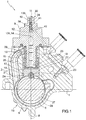
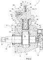
- the pump unit 1 comprises a piston pump 2 for supplying the fuel to the aforementioned internal combustion engine (not shown) and a prefeed pump 3, for example a gear pump, for supplying the fuel to the pump 2.
- the pump unit 1 has a pump body which comprises a housing 4 which is provided with a central bore 5 which has a longitudinal axis 6 and with at least one lateral bore 7 (normally a plurality of bores 7 which are uniformly about the axis 6 are distributed), which has a longitudinal axis 8, which runs transversely to the axis 6 and extends radially outward from the housing 4 starting from the bore 5.
- Each bore 7 is closed by a head part 9 which is arranged in contact with the housing 4 and has an extension 10 which projects into the bore 7 coaxially to the axis 8.
- the head part 9 has a central bore 11, which is formed through the head part 9 coaxially to the axis 8, and comprises a narrowed intermediate section 12, which is arranged between two widened sections 13a, 13b, the section 13a facing the bore 5 and defines a cylinder 14 of the piston pump 2.
- a piston 15 is slidably disposed in the cylinder 14 and is movable under the thrust of an actuator 16 with a straight forward and backward movement which includes a suction stroke for sucking the fuel into the cylinder 14 and a compression stroke for compressing the fuel contained in the cylinder 14 .
- the device 16 comprises a tubular sleeve 17 which is displaceably arranged in the bore 7 coaxially to the axis 8, extends around the cylinder 14 and has an annular inner flange 18 which projects radially from an inner surface of the sleeve 17 and this sleeve 17 in divides two cylindrical sections 19, 20, the section 19 facing the bore 5.
- the device 16 also has a tappet 21, which comprises a substantially cylindrical coupling block 22, which is held in place by an oversize in the section 19, is arranged in contact with the flange 18 and carries a tappet roller 23.
- the roller 23 projects from the block 22 to the bore 5 and is rotatably coupled to the block 22 in order to rotate with respect to this block 22 about its own longitudinal axis 24, which is essentially perpendicular to the axis 8.
- the flange 18 carries an annular plate 25 which extends around the piston 15, is inserted into the section 20 of the sleeve 17 coaxial to the axis 8 and an outer peripheral edge which axially faces the flange 18 and an inner peripheral edge which axially facing a bottom of the piston 15.
- the device 16 further includes a compression spring 26 which is mounted between the extension 10 and the sleeve 17 coaxially to the axis 8 and which sits between the head part 9 and the plate 25 to move the plate 25 into contact with the flange 18 and normally to hold and normally move and hold the roller 23 in contact with a cam 27 formed on an outer surface of an intermediate portion of a drive shaft 28 which is fitted through the bore 5 to rotate with respect to the housing 4 about the axis 6 to turn.
- a compression spring 26 which is mounted between the extension 10 and the sleeve 17 coaxially to the axis 8 and which sits between the head part 9 and the plate 25 to move the plate 25 into contact with the flange 18 and normally to hold and normally move and hold the roller 23 in contact with a cam 27 formed on an outer surface of an intermediate portion of a drive shaft 28 which is fitted through the bore 5 to rotate with respect to the housing 4 about the axis 6 to turn.
- the head part 9 accommodates in its interior a suction valve 29 for sucking the fuel into the cylinder 14 and a pressure valve 30 for pushing the fuel to the internal combustion engine (not shown).
- the valve 29 is mounted in a suction line 31, which has a longitudinal axis 32 running perpendicular to the axis 8, and comprises a cylindrical valve body 33, which extends around the axis 32 and axially along the line 31 through a cover 34, which goes into the Line 31 is screwed, is held.
- the valve 29 further includes a closure member 35 which is attached through the valve body 33 to move between an open position and a closed position of the valve 29.
- the closure part 35 is moved into its closed position by a spring 36, which is seated between the valve body 33 and an annular plate 37, which is attached to the closure part 35 transversely to the axis 32, and is normally held there.
- the valve 30 controls the supply of fuel along a pressure line defined through the head part 9 through the sections 12 and 13b and comprises a cup-shaped closure part 38 which is slidably arranged in the section 13b and between an open position and a closed position of the valve 30 is movable.
- the closure part 38 is moved into its closed position by a spring 39, which sits between the closure 38 and a stop sleeve 40 attached in section 13b, and is normally held there.
- the sections 12, 13b are connected to one another by a shoulder which is provided with a substantially frustoconical coupling section 41 which is designed in such a way that it couples in a fluid-tight manner to a substantially spherical coupling section 42 of the closure part 38.
- the closure part 38 is axially delimited by a free end surface 43 which faces the piston 15 and is provided with a cavity 44 which has a substantially hemispherical shape and which extends outward on a substantially flat and perpendicular to the axis 8 middle Section 45 of surface 43 opens.
- Figure 3 shows an embodiment of cavity 44 not according to the invention.
- FIG 4 variant shown differs from the representation in Figure 3 only in that the closure part 38 was removed in it and replaced by a closure part 46 which has an extension 47 which protrudes into the section 12 and is axially delimited by an essentially flat end surface 48 running perpendicular to the axis 8.
- the extension 47 has a cross section which is smaller than the cross section of the section 12 and is provided with a cavity 49 which has a substantially cylindrical shape, extends coaxially with the axis 8 and opens outwards on the surface 48.
- the cavity 49 communicates with the section 12 via a plurality of radial bores 50, which are evenly distributed around the axis 8 and are formed through a side wall of the cavity 49 transversely to the axis 8.
- Figure 4 shows an embodiment of cavity 49 not according to the invention.
- the closure part 51 is provided with a cavity 53 which has an annular shape, extends around the axis 8 and opens outwards at a lateral, essentially spherical section 54 of the surface 52.
- the piston 15 In operation, the piston 15 generates pressure waves in the cylinder 14 during its compression stroke.
- the cavities 44, 49, 53 make it possible to concentrate the vapor bubbles in their interior, prevent the vapor bubbles from reaching the coupling sections 41, 42, prevent wear due to cavitation of the coupling sections 41, 42 and thereby guarantee the perfect fluid-tight coupling of the closure parts 38 , 46, 51 with the head part 9.
Landscapes
- Engineering & Computer Science (AREA)
- Mechanical Engineering (AREA)
- General Engineering & Computer Science (AREA)
- Chemical & Material Sciences (AREA)
- Combustion & Propulsion (AREA)
- Fuel-Injection Apparatus (AREA)
- Lift Valve (AREA)
Description
- Die vorliegende Erfindung bezieht sich auf ein Pumpenaggregat zum Zuführen von Kraftstoff, bevorzugt Diesel, zu einem Verbrennungsmotor.
- Im Besonderen bezieht sich die vorliegende Erfindung auf ein Pumpenaggregat des Typs, der einen Pumpenkörper, mindestens einen im Pumpenkörper ausgebildeten Zylinder, einen im Zylinder verschieblich angeordneten Kolben und eine Betätigungsvorrichtung, um den Kolben bei einem Ansaughub zum Ansaugen des Kraftstoffs in den Zylinder und bei einem Verdichtungshub zum Verdichten des im Zylinder enthaltenen Kraftstoffs zu bewegen, umfasst. Ein solches Pumpenaggregat ist durch das Dokument
WO 2010/130502 A1 bekannt. Auch durch das DokumentWO 2015/091264 A1 ist ein solches Pumpenaggregat bekannt. - Das Pumpenaggregat umfasst ferner eine Saugleitung zum Ansaugen des Kraftstoffs in den Zylinder, ein Saugventil, das entlang der Saugleitung angebracht ist, um das Zuführen des Kraftstoffs in den Zylinder selektiv zu steuern, eine Druckleitung zum Drücken des Kraftstoffs zum Verbrennungsmotor und ein Druckventil, das entlang der Druckleitung angebracht ist, um das Zuführen des Kraftstoffs zum Verbrennungsmotor selektiv zu steuern.
- Die Druckleitung verläuft koaxial zu einer Längsachse des Zylinders, und in ihr ist verschieblich ein Verschlussteil des Druckventils angeordnet.
- Das Verschlussteil des Druckventils ist somit axial dem Kolben zugewandt und ist zwischen einer Öffnungsstellung und einer Schließstellung der Druckleitung beweglich.
- Das Verschlussteil weist einen im Wesentlichen kugelförmigen Kupplungsabschnitt auf, der so gestaltet ist, dass er sich fluiddicht mit einem im Wesentlichen kegelstumpfförmigen Kupplungsabschnitt der Druckleitung kuppelt, wenn sich das Verschlussteil in seiner Schließstellung befindet.
- Die bekannten Pumpenaggregate des oben genannten Typs weisen einige Nachteile auf, die hauptsächlich darauf beruhen, dass der Kolben während seines Verdichtungshubs im Innern des Zylinders Druckwellen erzeugt, die zwischen dem Verschlussteil des Druckventils und dem Kolben parallel zur Längsachse des Zylinders mindestens während der Anfangsphase des Verdichtungshubs des Kolbens, d. h. wenn das Druckventil noch geschlossen ist, abprallen.
- Die Hin- und Herbewegung der Druckwellen zwischen dem Verschlussteil und dem Kolben bewirkt die Entstehung von Dampfblasen und deren Implosion an den Kupplungsabschnitten des Verschlussteils und der Druckleitung.
- Das Implodieren der Dampfblasen führt durch Kavitation zum Verschleiß des Verschlussteils und der Druckleitung an den jeweiligen Kupplungsabschnitten und beeinträchtigt dadurch die einwandfreie fluiddichte Kupplung des Verschlussteils mit der Druckleitung.
- Durch das Dokument
DE 10 2010 039501 A1 ist ein Druckventil bekannt, das ein Verschlussteil aufweist, das an dessen einem Kolben zugewandter Endfläche eine Kavität aufweist, die sich nach außen hin an der Endfläche öffnet und die mit einem Zylinder kommuniziert, in dem der Kolben angeordnet ist. Die Kavität ist zentral in der Endfläche angeordnet und durch diese soll das Öffnungsverhalten des Druckventils verbessert werden. - Durch das Dokument
EP 0 209 938 A1 ist ein Druckventil bekannt, das ein Verschlussteil aufweist, das an dessen einem Kolben zugewandter Endfläche eine zylindrische Kavität aufweist, die sich nach außen hin an der Endfläche öffnet und die mit einem Zylinder kommuniziert, in dem der Kolben angeordnet ist. Die Kavität dient zur Durchströmung des Verschlussteils, wobei sich an die Kavität auf deren dem Zylinder abgewandter Seite Querbohrungen anschließen. - Aufgabe dieser Erfindung ist es, ein Pumpenaggregat zum Zuführen von Kraftstoff, bevorzugt Diesel, zu einem Verbrennungsmotor auszuführen, bei im Bereich des Druckventils Kavitation verringert ist.
- Gemäß der vorliegenden Erfindung wird ein Pumpenaggregat zum Zuführen von Kraftstoff, bevorzugt Diesel, zu einem Verbrennungsmotor nach den beigefügten Ansprüchen ausgeführt.
- Diese Erfindung wird nun unter Bezugnahme auf die beigefügten Zeichnungen beschrieben, die eine nicht einschränkende Ausführungsform darstellen. In diesen zeigen:
-
Figur 1 eine erste schematische Schnittansicht, mit zur Verdeutlichung weggelassenen Teilen, einer Ausführungsform eines Pumpenaggregats; -
Figur 2 eine zweite schematische Schnittansicht, mit zur Verdeutlichung weggelassenen Teilen, des Pumpenaggregats ausFigur 1 ; -
Figur 3 eine schematische Schnittansicht eines Details des Pumpenaggregats aus denFiguren 1 und2 gemäß einer nicht erfindungsgemäßen Ausführungsform; -
Figur 4 eine schematische Schnittansicht einer ersten nicht erfindungsgemäßen Variante des Details ausFigur 3 und -
Figur 5 eine schematische Schnittansicht einer zweiten, erfindungsgemäßen Variante des Details ausFigur 3 . - Unter Bezugnahme auf die
Figuren 1 und2 wird mit 1 ein Pumpenaggregat zum Zuführen von Kraftstoff, bevorzugt Diesel, zu einem Verbrennungsmotor (nicht dargestellt) im Ganzen bezeichnet. - Das Pumpenaggregat 1 umfasst eine Kolbenpumpe 2 zum Zuführen des Kraftstoffs zu dem genannten Verbrennungsmotor (nicht dargestellt) und eine Vorförderpumpe 3, beispielsweise eine Zahnradpumpe, zum Zuführen des Kraftstoffs zu der Pumpe 2.
- Das Pumpenaggregat 1 weist einen Pumpenkörper auf, der ein Gehäuse 4 umfasst, das mit einer zentralen Bohrung 5 versehen ist, die eine Längsachse 6 besitzt, und mit mindestens einer seitlichen Bohrung 7 (normalerweise einer Vielzahl von Bohrungen 7, die gleichmäßig um die Achse 6 verteilt sind), die eine Längsachse 8 besitzt, die quer zur Achse 6 verläuft und sich ausgehend von der Bohrung 5 radial nach außerhalb des Gehäuses 4 erstreckt.
- Jede Bohrung 7 wird von einem Kopfteil 9 verschlossen, das in Kontakt mit dem Gehäuse 4 angeordnet ist und eine Verlängerung 10 aufweist, die koaxial zur Achse 8 in die Bohrung 7 hineinragt.
- Das Kopfteil 9 weist eine zentrale Bohrung 11 auf, die durch das Kopfteil 9 hindurch koaxial zur Achse 8 ausgebildet ist, und umfasst einen eingeengten Zwischenabschnitt 12, der zwischen zwei aufgeweiteten Abschnitten 13a, 13b angeordnet ist, wobei der Abschnitt 13a der Bohrung 5 zugewandt ist und einen Zylinder 14 der Kolbenpumpe 2 definiert.
- Im Zylinder 14 ist verschieblich ein Kolben 15 angeordnet, der unter dem Schub einer Betätigungsvorrichtung 16 mit einer geradlinigen Hin- und Herbewegung beweglich ist, die einen Saughub zum Ansaugen des Kraftstoffs in den Zylinder 14 und einen Verdichtungshub zum Verdichten des im Zylinder 14 enthaltenen Kraftstoffs umfasst.
- Die Vorrichtung 16 umfasst eine rohrförmige Hülse 17, die verschieblich in der Bohrung 7 koaxial zur Achse 8 angeordnet ist, sich um den Zylinder 14 herum erstreckt und einen ringförmigen Innenflansch 18 aufweist, der radial aus einer Innenfläche der Hülse 17 herausragt und diese Hülse 17 in zwei zylindrische Abschnitte 19, 20 teilt, wobei der Abschnitt 19 der Bohrung 5 zugewandt ist.
- Die Vorrichtung 16 weist ferner einen Stößel 21 auf, der einen im Wesentlichen zylindrischen Kupplungsblock 22 umfasst, der durch Übermaß im Abschnitt 19 festgehalten ist, im Kontakt mit dem Flansch 18 angeordnet ist und eine Stößelrolle 23 trägt.
- Die Rolle 23 ragt vom Block 22 aus zur Bohrung 5 vor und ist drehbar mit dem Block 22 gekuppelt, um in Bezug auf diesen Block 22 um eine eigene Längsachse 24 zu drehen, die im Wesentlichen senkrecht zur Achse 8 verläuft.
- Der Flansch 18 trägt einen ringförmigen Teller 25, der sich um den Kolben 15 herum erstreckt, in den Abschnitt 20 der Hülse 17 koaxial zur Achse 8 eingesetzt ist und einen äußeren Umfangsrand, der axial dem Flansch 18 zugewandt ist, und einen inneren Umfangsrand, der axial einem Boden des Kolbens 15 zugewandt ist, aufweist.
- Die Vorrichtung 16 umfasst ferner eine Druckfeder 26, die zwischen der Verlängerung 10 und der Hülse 17 koaxial zur Achse 8 angebracht ist und zwischen dem Kopfteil 9 und dem Teller 25 sitzt, um den Teller 25 in Kontakt mit dem Flansch 18 zu bewegen und normalerweise zu halten und die Rolle 23 in Kontakt mit einem Nocken 27 zu bewegen und normalerweise zu halten, der an einer Außenfläche eines Zwischenabschnitts einer Antriebswelle 28 ausgebildet ist, die durch die Bohrung 5 hindurch angebracht ist, um in Bezug auf das Gehäuse 4 um die Achse 6 zu drehen.
- Das Kopfteil 9 nimmt in seinem Innern ein Saugventil 29 zum Saugen des Kraftstoffs in den Zylinder 14 und ein Druckventil 30 zum Drücken des Kraftstoffs zum Verbrennungsmotor (nicht dargestellt) auf.
- Das Ventil 29 ist in einer Saugleitung 31 angebracht, die eine senkrecht zur Achse 8 verlaufende Längsachse 32 aufweist, und umfasst einen zylindrischen Ventilkörper 33, der sich um die Achse 32 herum erstreckt und axial entlang der Leitung 31 durch einen Verschlussdeckel 34, der in die Leitung 31 geschraubt ist, festgehalten wird.
- Das Ventil 29 umfasst ferner ein Verschlussteil 35, das durch den Ventilkörper 33 hindurch angebracht ist, um sich zwischen einer Öffnungsstellung und einer Schließstellung des Ventils 29 zu bewegen. Das Verschlussteil 35 wird von einer Feder 36, die zwischen dem Ventilkörper 33 und einem ringförmigen, am Verschlussteil 35 quer zur Achse 32 angebrachten Teller 37 sitzt, in seine Schließstellung bewegt und normalerweise dort gehalten.
- Das Ventil 30 steuert das Zuführen des Kraftstoffs entlang einer Druckleitung, die durch das Kopfteil 9 hindurch durch die Abschnitte 12 und 13b definiert wird, und umfasst ein becherförmiges Verschlussteil 38, das verschieblich im Abschnitt 13b angeordnet ist und zwischen einer Öffnungsstellung und einer Schließstellung des Ventils 30 beweglich ist.
- Das Verschlussteil 38 wird von einer Feder 39, die zwischen dem Verschluss 38 und einer im Abschnitt 13b angebrachten Anschlaghülse 40 sitzt, in seine Schließstellung bewegt und normalerweise dort gehalten.
- Gemäß der Darstellung in
Figur 3 sind die Abschnitte 12, 13b untereinander durch eine Schulter verbunden, die mit einem im Wesentlichen kegelstumpfförmigen Kupplungsabschnitt 41 versehen ist, der so gestaltet ist, dass er sich fluiddicht mit einem im Wesentlichen kugelförmigen Kupplungsabschnitt 42 des Verschlussteils 38 kuppelt. - Das Verschlussteil 38 wird axial durch eine freie Endfläche 43 begrenzt, die dem Kolben 15 zugewandt ist, und ist mit einer Kavität 44 versehen, die eine im Wesentlichen halbkugelige Form aufweist und sich nach außen hin an einem im Wesentlichen ebenen und senkrecht zur Achse 8 verlaufenden mittleren Abschnitt 45 der Fläche 43 öffnet.
Figur 3 zeigt eine nicht erfindungsgemäße Ausführungsform der Kavität 44. - Die in
Figur 4 dargestellte Variante unterscheidet sich von der Darstellung inFigur 3 nur dadurch, dass in ihr das Verschlussteil 38 entfernt wurde und durch ein Verschlussteil 46 ersetzt wurde, das eine Verlängerung 47 aufweist, die in den Abschnitt 12 hineinragt, und axial durch eine im Wesentlichen ebene und senkrecht zur Achse 8 verlaufende Endfläche 48 begrenzt wird. - Die Verlängerung 47 weist einen Querschnitt auf, der kleiner als der Querschnitt des Abschnitts 12 ist, und ist mit einer Kavität 49 versehen, die eine im Wesentlichen zylindrische Form aufweist, koaxial zur Achse 8 verläuft und sich nach außen hin an der Fläche 48 öffnet.
- Die Kavität 49 kommuniziert mit dem Abschnitt 12 über eine Vielzahl von radialen Bohrungen 50, die gleichmäßig um die Achse 8 herum verteilt sind und durch eine Seitenwand der Kavität 49 hindurch quer zur Achse 8 ausgebildet sind.
Figur 4 zeigt eine nicht erfindungsgemäße Ausführungsform der Kavität 49. - Die in
Figur 5 dargestellte erfindungsgemäße Variante unterscheidet sich von der Darstellung inFigur 3 nur dadurch, dass in ihr das Verschlussteil 38 entfernt wurde und durch ein Verschlussteil 51 ersetzt wurde, das axial durch eine freie Endfläche 52 begrenzt wird, die dem Kolben 15 zugewandt ist. - Das Verschlussteil 51 ist mit einer Kavität 53 versehen, die eine Ringform aufweist, sich um die Achse 8 herum erstreckt und sich nach außen hin an einem seitlichen, im Wesentlichen kugelförmigen Abschnitt 54 der Fläche 52 öffnet.
- Im Betrieb erzeugt der Kolben 15 während seines Verdichtungshubs Druckwellen im Zylinder 14.
- Mindestens während der Anfangsphase des Verdichtungshubs des Kolbens 15, d. h. wenn das Druckventil 30 noch geschlossen ist, prallen die Druckwellen zwischen den Verschlussteilen 38, 46, 51 und dem Kolben 15 mit einer Hin- und Herbewegung ab, die die Entstehung von Dampfblasen bewirkt.
- Die Kavitäten 44, 49, 53 ermöglichen es, die Dampfblasen in ihrem Innern zu konzentrieren, verhindern, dass die Dampfblasen die Kupplungsabschnitte 41, 42 erreichen, verhindern den Verschleiß durch Kavitation der Kupplungsabschnitte 41, 42 und garantieren dadurch die einwandfreie fluiddichte Kupplung der Verschlussteile 38, 46, 51 mit dem Kopfteil 9.
Claims (5)
- Pumpenaggregat zum Zuführen von Kraftstoff, bevorzugt Diesel, zu einem Verbrennungsmotor, umfassend einen Pumpenkörper (4, 9), mindestens einen im Pumpenkörper (4, 9) ausgebildeten Zylinder (14), einen im Zylinder (14) verschieblich angeordneten Kolben (15), eine Betätigungsvorrichtung (16) zum Bewegen des Kolbens (15) bei einem Ansaughub zum Ansaugen des Kraftstoffs in den Zylinder (14) und bei einem Verdichtungshub zum Verdichten des im Zylinder (14) enthaltenen Kraftstoffs, ein Saugventil (29) zum selektiven Steuern der Zuführung des Kraftstoffs in den Zylinder (14) und ein Druckventil (30) zum selektiven Steuern der Zuführung des Kraftstoffs zum Verbrennungsmotor, wobei das Druckventil (30) ein Verschlussteil (51) umfasst, das koaxial zu einer Längsachse (8) des Zylinders (14) angebracht ist, axial durch eine dem Kolben (15) zugewandte Endfläche (52) begrenzt wird und zwischen einer Öffnungsstellung und einer Schließstellung des Druckventils (30) beweglich ist, dadurch gekennzeichnet, dass das Verschlussteil (51) eine Kavität (53) aufweist, die sich nach außen hin an der Endfläche (52) öffnet und mit dem Zylinder (14) kommuniziert, und dass die Kavität (53) eine Ringform aufweist.
- Pumpenaggregat nach Anspruch 1, wobei sich die Kavität (53) um die Längsachse (8) herum erstreckt.
- Pumpenaggregat nach Anspruch 1 oder 2, wobei die Endfläche (52) einen kugelförmigen seitlichen Abschnitt (54) umfasst, wobei sich die Kavität (53) nach außen hin an dem seitlichen Abschnitt (54) öffnet.
- Pumpenaggregat nach einem der Ansprüche 1 bis 3, umfassend ferner eine Druckleitung (12, 13b), die durch den Pumpenkörper (4, 9) hindurch ausgebildet ist und ihrerseits einen aufgeweiteten Abschnitt (13b), der mit dem Verbrennungsmotor verbunden ist, und einen verengten Abschnitt (12), der mit dem Zylinder (14) verbunden ist, umfasst.
- Pumpenaggregat nach Anspruch 4, wobei die verengten und aufgeweiteten Abschnitte (12, 13b) untereinander durch eine Schulter verbunden sind, die mit einem kegelstumpfförmigen Kupplungsabschnitt (41) versehen ist, der so gestaltet ist, dass er sich fluiddicht mit einem kugelförmigen Kupplungsabschnitt (42) des Verschlussteils (51) kuppelt.
Applications Claiming Priority (2)
| Application Number | Priority Date | Filing Date | Title |
|---|---|---|---|
| IT102016000131338A IT201600131338A1 (it) | 2016-12-27 | 2016-12-27 | Gruppo di pompaggio per alimentare combustibile, preferibilmente gasolio, ad un motore a combustione interna |
| PCT/EP2017/083015 WO2018122005A1 (de) | 2016-12-27 | 2017-12-15 | Pumpenaggregat zum zuführen von kraftstoff, bevorzugt diesel, zu einem verbrennungsmotor |
Publications (2)
| Publication Number | Publication Date |
|---|---|
| EP3563058A1 EP3563058A1 (de) | 2019-11-06 |
| EP3563058B1 true EP3563058B1 (de) | 2020-07-15 |
Family
ID=58670243
Family Applications (1)
| Application Number | Title | Priority Date | Filing Date |
|---|---|---|---|
| EP17818534.4A Active EP3563058B1 (de) | 2016-12-27 | 2017-12-15 | Pumpenaggregat zum zuführen von kraftstoff, bevorzugt diesel, zu einem verbrennungsmotor |
Country Status (7)
| Country | Link |
|---|---|
| US (1) | US10954907B2 (de) |
| EP (1) | EP3563058B1 (de) |
| JP (1) | JP6887504B2 (de) |
| KR (1) | KR20190100953A (de) |
| CN (1) | CN110121593B (de) |
| IT (1) | IT201600131338A1 (de) |
| WO (1) | WO2018122005A1 (de) |
Families Citing this family (1)
| Publication number | Priority date | Publication date | Assignee | Title |
|---|---|---|---|---|
| IT201900018122A1 (it) * | 2019-10-07 | 2021-04-07 | Bosch Gmbh Robert | Gruppo di pompaggio per alimentare un fluido, in particolare combustibile, preferibilmente gasolio, ad una utenza, in particolare un motore a combustione interna |
Family Cites Families (15)
| Publication number | Priority date | Publication date | Assignee | Title |
|---|---|---|---|---|
| US3100449A (en) * | 1959-02-04 | 1963-08-13 | Borg Warner | Fuel injection pump |
| JPS59229793A (ja) | 1983-06-10 | 1984-12-24 | Fujitsu Ltd | 遅延量可変形シフトレジスタ |
| IT1200685B (it) * | 1985-07-22 | 1989-01-27 | Piaggio & C Spa | Pompa meccanica di iniezione di combustibile,in particolare permotori a combustione interna ad accensione comandata |
| IT1198062B (it) * | 1986-10-22 | 1988-12-21 | Piaggio & C Spa | Motore a combustione interna a due tempi,ad iniezione di combustibile ed accensione comandata |
| DE4037465A1 (de) * | 1990-10-31 | 1992-05-07 | Daimler Benz Ag | Kraftstoffeinspritzpumpe fuer brennkraftmaschinen |
| JP3221033B2 (ja) * | 1992-03-06 | 2001-10-22 | 株式会社デンソー | 燃料噴射ポンプ用の定残圧弁 |
| US6668797B2 (en) * | 2002-05-13 | 2003-12-30 | Advanced Vehicle Technologies | Fuel injection pump system |
| DE10254711B3 (de) * | 2002-11-23 | 2004-04-15 | Motorenfabrik Hatz Gmbh & Co Kg | Druckventil mit zusätzlicher Spritzverstellerfunktion |
| JP2004270641A (ja) * | 2003-03-11 | 2004-09-30 | Yanmar Co Ltd | ディーゼルエンジン |
| JP2005248319A (ja) | 2004-02-06 | 2005-09-15 | Tokyo Univ Of Science | 有機溶媒のゲル電解質を用いた金属の電気めっき方法 |
| EP1857667B1 (de) * | 2006-05-19 | 2009-12-09 | Centro Studi Componenti per Veicoli S.P.A. | Kraftstoffhochdruckpumpe |
| IT1394070B1 (it) * | 2009-05-13 | 2012-05-25 | Bosch Gmbh Robert | Gruppo valvola per controllare l'alimentazione e la mandata di combustibile di una camera di compressione di una pompa a pistoni di alta pressione e pompa a pistoni di alta pressione comprendente tale gruppo valvola |
| DE102010039501A1 (de) * | 2010-08-19 | 2012-02-23 | Robert Bosch Gmbh | Ventil einer Kolbenpumpe mit einem Schließkörper |
| ITMI20132109A1 (it) * | 2013-12-17 | 2015-06-18 | Bosch Gmbh Robert | Gruppo pompa per alimentare combustibile, preferibilmente gasolio, ad un motore a combustione interna |
| CN105248319A (zh) | 2015-09-28 | 2016-01-20 | 曹全民 | 一种罗非鱼养殖方法 |
-
2016
- 2016-12-27 IT IT102016000131338A patent/IT201600131338A1/it unknown
-
2017
- 2017-12-15 JP JP2019534857A patent/JP6887504B2/ja active Active
- 2017-12-15 EP EP17818534.4A patent/EP3563058B1/de active Active
- 2017-12-15 WO PCT/EP2017/083015 patent/WO2018122005A1/de not_active Ceased
- 2017-12-15 KR KR1020197021707A patent/KR20190100953A/ko not_active Withdrawn
- 2017-12-15 US US16/474,255 patent/US10954907B2/en active Active
- 2017-12-15 CN CN201780081020.8A patent/CN110121593B/zh active Active
Non-Patent Citations (1)
| Title |
|---|
| None * |
Also Published As
| Publication number | Publication date |
|---|---|
| US10954907B2 (en) | 2021-03-23 |
| JP2020503473A (ja) | 2020-01-30 |
| JP6887504B2 (ja) | 2021-06-16 |
| CN110121593A (zh) | 2019-08-13 |
| IT201600131338A1 (it) | 2018-06-27 |
| US20200124008A1 (en) | 2020-04-23 |
| WO2018122005A1 (de) | 2018-07-05 |
| CN110121593B (zh) | 2021-05-14 |
| KR20190100953A (ko) | 2019-08-29 |
| EP3563058A1 (de) | 2019-11-06 |
Similar Documents
| Publication | Publication Date | Title |
|---|---|---|
| AT511803B1 (de) | Pleuelstange für eine hubkolbenmaschine | |
| DE112011105490B4 (de) | Kraftstoffpumpe | |
| EP3027885B1 (de) | Kraftstoffhochdruckpumpe, mit einem auslassventil | |
| DE60217705T2 (de) | Einlassventil für eine hochdruckpumpe, insbesondere für kraftstoff einer brennkraftmaschine | |
| WO2009013041A1 (de) | Hochdruckpumpe für ein kraftstoffsystem einer brennkraftmaschine | |
| DE102008045730A1 (de) | Kraftstoffeinspritzpumpe mit geringer Rückflusspulsation | |
| EP2705235B1 (de) | Verfahren und vorrichtung zum steuern eines ventils | |
| WO2017025579A1 (de) | Hubkolbenmaschine, insbesondere brennkraftmaschine | |
| EP1234975A2 (de) | Hochdruck-Kolbenzylindereinheit | |
| WO2016058805A1 (de) | Elektromagnetisch betätigbares einlassventil und hochdruckpumpe mit einlassventil | |
| EP3152434B1 (de) | Kraftstoff-hochdruckpumpe, mit einem auslassventil mit einer ventilkugel und einem ventilkörper | |
| DE102007047903A1 (de) | Kraftstoffeinspritzpumpe | |
| DE102005022661A1 (de) | Fluidpumpe, insbesondere Kraftstoff-Hochdruckpumpe für eine Brennkraftmaschine mit Kraftstoff-Direkteinspritzung | |
| EP3563058B1 (de) | Pumpenaggregat zum zuführen von kraftstoff, bevorzugt diesel, zu einem verbrennungsmotor | |
| EP2519732B1 (de) | Elektromagnetisch betätigtes mengensteuerventil, insbesondere zur steuerung der fördermenge einer kraftstoff-hochdruckpumpe | |
| DE102017217500A1 (de) | Längenverstellbares Pleuel mit mechanischer Verstellung | |
| DE602004006121T2 (de) | Brennkraftmaschine mit variabler und hydraulischer Ventilsteuerung durch Kipphebel | |
| DE102016218846A1 (de) | Elektromagnetisch betätigbares Einlassventil und Kraftstoff-Hochdruckpumpe | |
| WO2018001626A1 (de) | Elektromagnetisch betätigbares einlassventil und hochdruckpumpe mit einlassventil | |
| DE112016005545T5 (de) | Druckentlastungsventilvorrichtung und Hochdruckpumpe unter Verwendung derselben | |
| DE102015224421A1 (de) | Elektromagnetisch betätigbares Einlassventil und Hochdruckpumpe mit Einlassventil | |
| DE19951052C2 (de) | Motorbremsvorrichtung für eine Verbrennungskraftmaschine | |
| EP3390807B1 (de) | Ventil in einer hochdruckpumpe eines kraftstoffeinspritzsystems | |
| DE102007038523A1 (de) | Kraftstoffhochdruckpumpe | |
| DE102006055187B3 (de) | Wärmekraftmaschine mit einer Ventilanordnung und Ventilsteuerung für eine solche Ventilanordnung |
Legal Events
| Date | Code | Title | Description |
|---|---|---|---|
| STAA | Information on the status of an ep patent application or granted ep patent |
Free format text: STATUS: UNKNOWN |
|
| STAA | Information on the status of an ep patent application or granted ep patent |
Free format text: STATUS: THE INTERNATIONAL PUBLICATION HAS BEEN MADE |
|
| PUAI | Public reference made under article 153(3) epc to a published international application that has entered the european phase |
Free format text: ORIGINAL CODE: 0009012 |
|
| STAA | Information on the status of an ep patent application or granted ep patent |
Free format text: STATUS: REQUEST FOR EXAMINATION WAS MADE |
|
| 17P | Request for examination filed |
Effective date: 20190729 |
|
| AK | Designated contracting states |
Kind code of ref document: A1 Designated state(s): AL AT BE BG CH CY CZ DE DK EE ES FI FR GB GR HR HU IE IS IT LI LT LU LV MC MK MT NL NO PL PT RO RS SE SI SK SM TR |
|
| AX | Request for extension of the european patent |
Extension state: BA ME |
|
| DAV | Request for validation of the european patent (deleted) | ||
| DAX | Request for extension of the european patent (deleted) | ||
| REG | Reference to a national code |
Ref country code: DE Ref legal event code: R079 Ref document number: 502017006286 Country of ref document: DE Free format text: PREVIOUS MAIN CLASS: F04B0001040000 Ipc: F04B0001042100 |
|
| GRAP | Despatch of communication of intention to grant a patent |
Free format text: ORIGINAL CODE: EPIDOSNIGR1 |
|
| STAA | Information on the status of an ep patent application or granted ep patent |
Free format text: STATUS: GRANT OF PATENT IS INTENDED |
|
| RAP1 | Party data changed (applicant data changed or rights of an application transferred) |
Owner name: ROBERT BOSCH GMBH |
|
| RIC1 | Information provided on ipc code assigned before grant |
Ipc: F04B 1/0439 20200101ALI20200402BHEP Ipc: F02M 59/10 20060101ALI20200402BHEP Ipc: F04B 17/05 20060101ALI20200402BHEP Ipc: F04B 1/0452 20200101ALI20200402BHEP Ipc: F02M 59/46 20060101ALI20200402BHEP Ipc: F04B 1/0421 20200101AFI20200402BHEP |
|
| INTG | Intention to grant announced |
Effective date: 20200420 |
|
| GRAS | Grant fee paid |
Free format text: ORIGINAL CODE: EPIDOSNIGR3 |
|
| GRAA | (expected) grant |
Free format text: ORIGINAL CODE: 0009210 |
|
| STAA | Information on the status of an ep patent application or granted ep patent |
Free format text: STATUS: THE PATENT HAS BEEN GRANTED |
|
| AK | Designated contracting states |
Kind code of ref document: B1 Designated state(s): AL AT BE BG CH CY CZ DE DK EE ES FI FR GB GR HR HU IE IS IT LI LT LU LV MC MK MT NL NO PL PT RO RS SE SI SK SM TR |
|
| REG | Reference to a national code |
Ref country code: GB Ref legal event code: FG4D Free format text: NOT ENGLISH Ref country code: CH Ref legal event code: EP |
|
| REG | Reference to a national code |
Ref country code: IE Ref legal event code: FG4D Free format text: LANGUAGE OF EP DOCUMENT: GERMAN |
|
| REG | Reference to a national code |
Ref country code: DE Ref legal event code: R096 Ref document number: 502017006286 Country of ref document: DE |
|
| REG | Reference to a national code |
Ref country code: AT Ref legal event code: REF Ref document number: 1291313 Country of ref document: AT Kind code of ref document: T Effective date: 20200815 |
|
| REG | Reference to a national code |
Ref country code: LT Ref legal event code: MG4D |
|
| REG | Reference to a national code |
Ref country code: NL Ref legal event code: MP Effective date: 20200715 |
|
| PG25 | Lapsed in a contracting state [announced via postgrant information from national office to epo] |
Ref country code: PT Free format text: LAPSE BECAUSE OF FAILURE TO SUBMIT A TRANSLATION OF THE DESCRIPTION OR TO PAY THE FEE WITHIN THE PRESCRIBED TIME-LIMIT Effective date: 20201116 Ref country code: LT Free format text: LAPSE BECAUSE OF FAILURE TO SUBMIT A TRANSLATION OF THE DESCRIPTION OR TO PAY THE FEE WITHIN THE PRESCRIBED TIME-LIMIT Effective date: 20200715 Ref country code: GR Free format text: LAPSE BECAUSE OF FAILURE TO SUBMIT A TRANSLATION OF THE DESCRIPTION OR TO PAY THE FEE WITHIN THE PRESCRIBED TIME-LIMIT Effective date: 20201016 Ref country code: ES Free format text: LAPSE BECAUSE OF FAILURE TO SUBMIT A TRANSLATION OF THE DESCRIPTION OR TO PAY THE FEE WITHIN THE PRESCRIBED TIME-LIMIT Effective date: 20200715 Ref country code: BG Free format text: LAPSE BECAUSE OF FAILURE TO SUBMIT A TRANSLATION OF THE DESCRIPTION OR TO PAY THE FEE WITHIN THE PRESCRIBED TIME-LIMIT Effective date: 20201015 Ref country code: NO Free format text: LAPSE BECAUSE OF FAILURE TO SUBMIT A TRANSLATION OF THE DESCRIPTION OR TO PAY THE FEE WITHIN THE PRESCRIBED TIME-LIMIT Effective date: 20201015 Ref country code: SE Free format text: LAPSE BECAUSE OF FAILURE TO SUBMIT A TRANSLATION OF THE DESCRIPTION OR TO PAY THE FEE WITHIN THE PRESCRIBED TIME-LIMIT Effective date: 20200715 Ref country code: HR Free format text: LAPSE BECAUSE OF FAILURE TO SUBMIT A TRANSLATION OF THE DESCRIPTION OR TO PAY THE FEE WITHIN THE PRESCRIBED TIME-LIMIT Effective date: 20200715 Ref country code: FI Free format text: LAPSE BECAUSE OF FAILURE TO SUBMIT A TRANSLATION OF THE DESCRIPTION OR TO PAY THE FEE WITHIN THE PRESCRIBED TIME-LIMIT Effective date: 20200715 |
|
| PG25 | Lapsed in a contracting state [announced via postgrant information from national office to epo] |
Ref country code: IS Free format text: LAPSE BECAUSE OF FAILURE TO SUBMIT A TRANSLATION OF THE DESCRIPTION OR TO PAY THE FEE WITHIN THE PRESCRIBED TIME-LIMIT Effective date: 20201115 Ref country code: LV Free format text: LAPSE BECAUSE OF FAILURE TO SUBMIT A TRANSLATION OF THE DESCRIPTION OR TO PAY THE FEE WITHIN THE PRESCRIBED TIME-LIMIT Effective date: 20200715 Ref country code: RS Free format text: LAPSE BECAUSE OF FAILURE TO SUBMIT A TRANSLATION OF THE DESCRIPTION OR TO PAY THE FEE WITHIN THE PRESCRIBED TIME-LIMIT Effective date: 20200715 Ref country code: PL Free format text: LAPSE BECAUSE OF FAILURE TO SUBMIT A TRANSLATION OF THE DESCRIPTION OR TO PAY THE FEE WITHIN THE PRESCRIBED TIME-LIMIT Effective date: 20200715 |
|
| PG25 | Lapsed in a contracting state [announced via postgrant information from national office to epo] |
Ref country code: NL Free format text: LAPSE BECAUSE OF FAILURE TO SUBMIT A TRANSLATION OF THE DESCRIPTION OR TO PAY THE FEE WITHIN THE PRESCRIBED TIME-LIMIT Effective date: 20200715 |
|
| REG | Reference to a national code |
Ref country code: DE Ref legal event code: R097 Ref document number: 502017006286 Country of ref document: DE |
|
| PG25 | Lapsed in a contracting state [announced via postgrant information from national office to epo] |
Ref country code: EE Free format text: LAPSE BECAUSE OF FAILURE TO SUBMIT A TRANSLATION OF THE DESCRIPTION OR TO PAY THE FEE WITHIN THE PRESCRIBED TIME-LIMIT Effective date: 20200715 Ref country code: RO Free format text: LAPSE BECAUSE OF FAILURE TO SUBMIT A TRANSLATION OF THE DESCRIPTION OR TO PAY THE FEE WITHIN THE PRESCRIBED TIME-LIMIT Effective date: 20200715 Ref country code: CZ Free format text: LAPSE BECAUSE OF FAILURE TO SUBMIT A TRANSLATION OF THE DESCRIPTION OR TO PAY THE FEE WITHIN THE PRESCRIBED TIME-LIMIT Effective date: 20200715 Ref country code: DK Free format text: LAPSE BECAUSE OF FAILURE TO SUBMIT A TRANSLATION OF THE DESCRIPTION OR TO PAY THE FEE WITHIN THE PRESCRIBED TIME-LIMIT Effective date: 20200715 Ref country code: IT Free format text: LAPSE BECAUSE OF FAILURE TO SUBMIT A TRANSLATION OF THE DESCRIPTION OR TO PAY THE FEE WITHIN THE PRESCRIBED TIME-LIMIT Effective date: 20200715 Ref country code: SM Free format text: LAPSE BECAUSE OF FAILURE TO SUBMIT A TRANSLATION OF THE DESCRIPTION OR TO PAY THE FEE WITHIN THE PRESCRIBED TIME-LIMIT Effective date: 20200715 |
|
| PLBE | No opposition filed within time limit |
Free format text: ORIGINAL CODE: 0009261 |
|
| STAA | Information on the status of an ep patent application or granted ep patent |
Free format text: STATUS: NO OPPOSITION FILED WITHIN TIME LIMIT |
|
| PG25 | Lapsed in a contracting state [announced via postgrant information from national office to epo] |
Ref country code: AL Free format text: LAPSE BECAUSE OF FAILURE TO SUBMIT A TRANSLATION OF THE DESCRIPTION OR TO PAY THE FEE WITHIN THE PRESCRIBED TIME-LIMIT Effective date: 20200715 |
|
| 26N | No opposition filed |
Effective date: 20210416 |
|
| PG25 | Lapsed in a contracting state [announced via postgrant information from national office to epo] |
Ref country code: SK Free format text: LAPSE BECAUSE OF FAILURE TO SUBMIT A TRANSLATION OF THE DESCRIPTION OR TO PAY THE FEE WITHIN THE PRESCRIBED TIME-LIMIT Effective date: 20200715 |
|
| REG | Reference to a national code |
Ref country code: CH Ref legal event code: PL |
|
| PG25 | Lapsed in a contracting state [announced via postgrant information from national office to epo] |
Ref country code: MC Free format text: LAPSE BECAUSE OF FAILURE TO SUBMIT A TRANSLATION OF THE DESCRIPTION OR TO PAY THE FEE WITHIN THE PRESCRIBED TIME-LIMIT Effective date: 20200715 |
|
| REG | Reference to a national code |
Ref country code: BE Ref legal event code: MM Effective date: 20201231 |
|
| PG25 | Lapsed in a contracting state [announced via postgrant information from national office to epo] |
Ref country code: IE Free format text: LAPSE BECAUSE OF NON-PAYMENT OF DUE FEES Effective date: 20201215 Ref country code: FR Free format text: LAPSE BECAUSE OF NON-PAYMENT OF DUE FEES Effective date: 20201231 Ref country code: LU Free format text: LAPSE BECAUSE OF NON-PAYMENT OF DUE FEES Effective date: 20201215 |
|
| PG25 | Lapsed in a contracting state [announced via postgrant information from national office to epo] |
Ref country code: LI Free format text: LAPSE BECAUSE OF NON-PAYMENT OF DUE FEES Effective date: 20201231 Ref country code: CH Free format text: LAPSE BECAUSE OF NON-PAYMENT OF DUE FEES Effective date: 20201231 |
|
| PG25 | Lapsed in a contracting state [announced via postgrant information from national office to epo] |
Ref country code: TR Free format text: LAPSE BECAUSE OF FAILURE TO SUBMIT A TRANSLATION OF THE DESCRIPTION OR TO PAY THE FEE WITHIN THE PRESCRIBED TIME-LIMIT Effective date: 20200715 Ref country code: MT Free format text: LAPSE BECAUSE OF FAILURE TO SUBMIT A TRANSLATION OF THE DESCRIPTION OR TO PAY THE FEE WITHIN THE PRESCRIBED TIME-LIMIT Effective date: 20200715 Ref country code: CY Free format text: LAPSE BECAUSE OF FAILURE TO SUBMIT A TRANSLATION OF THE DESCRIPTION OR TO PAY THE FEE WITHIN THE PRESCRIBED TIME-LIMIT Effective date: 20200715 |
|
| PG25 | Lapsed in a contracting state [announced via postgrant information from national office to epo] |
Ref country code: MK Free format text: LAPSE BECAUSE OF FAILURE TO SUBMIT A TRANSLATION OF THE DESCRIPTION OR TO PAY THE FEE WITHIN THE PRESCRIBED TIME-LIMIT Effective date: 20200715 |
|
| PG25 | Lapsed in a contracting state [announced via postgrant information from national office to epo] |
Ref country code: BE Free format text: LAPSE BECAUSE OF NON-PAYMENT OF DUE FEES Effective date: 20201231 |
|
| GBPC | Gb: european patent ceased through non-payment of renewal fee |
Effective date: 20211215 |
|
| PG25 | Lapsed in a contracting state [announced via postgrant information from national office to epo] |
Ref country code: GB Free format text: LAPSE BECAUSE OF NON-PAYMENT OF DUE FEES Effective date: 20211215 |
|
| PG25 | Lapsed in a contracting state [announced via postgrant information from national office to epo] |
Ref country code: SI Free format text: LAPSE BECAUSE OF FAILURE TO SUBMIT A TRANSLATION OF THE DESCRIPTION OR TO PAY THE FEE WITHIN THE PRESCRIBED TIME-LIMIT Effective date: 20200715 |
|
| REG | Reference to a national code |
Ref country code: AT Ref legal event code: MM01 Ref document number: 1291313 Country of ref document: AT Kind code of ref document: T Effective date: 20221215 |
|
| PG25 | Lapsed in a contracting state [announced via postgrant information from national office to epo] |
Ref country code: AT Free format text: LAPSE BECAUSE OF NON-PAYMENT OF DUE FEES Effective date: 20221215 |
|
| PG25 | Lapsed in a contracting state [announced via postgrant information from national office to epo] |
Ref country code: AT Free format text: LAPSE BECAUSE OF NON-PAYMENT OF DUE FEES Effective date: 20221215 |
|
| PGFP | Annual fee paid to national office [announced via postgrant information from national office to epo] |
Ref country code: DE Payment date: 20260223 Year of fee payment: 9 |
|
| PGFP | Annual fee paid to national office [announced via postgrant information from national office to epo] |
Ref country code: AT Payment date: 20260410 Year of fee payment: 5 |