EP3562359B1 - Ausschankvorrichtung für kalte getränke - Google Patents
Ausschankvorrichtung für kalte getränke Download PDFInfo
- Publication number
- EP3562359B1 EP3562359B1 EP17803960.8A EP17803960A EP3562359B1 EP 3562359 B1 EP3562359 B1 EP 3562359B1 EP 17803960 A EP17803960 A EP 17803960A EP 3562359 B1 EP3562359 B1 EP 3562359B1
- Authority
- EP
- European Patent Office
- Prior art keywords
- beverage
- mixing chamber
- heat exchanger
- outlet
- dispensing
- Prior art date
- Legal status (The legal status is an assumption and is not a legal conclusion. Google has not performed a legal analysis and makes no representation as to the accuracy of the status listed.)
- Not-in-force
Links
- 238000002360 preparation method Methods 0.000 title claims description 91
- 235000020965 cold beverage Nutrition 0.000 title claims description 23
- 235000013361 beverage Nutrition 0.000 claims description 393
- XLYOFNOQVPJJNP-UHFFFAOYSA-N water Substances O XLYOFNOQVPJJNP-UHFFFAOYSA-N 0.000 claims description 53
- 235000012171 hot beverage Nutrition 0.000 claims description 40
- 239000004615 ingredient Substances 0.000 claims description 40
- 239000012809 cooling fluid Substances 0.000 claims description 36
- 239000012530 fluid Substances 0.000 claims description 18
- 239000007788 liquid Substances 0.000 claims description 17
- 238000004140 cleaning Methods 0.000 claims description 14
- 238000000034 method Methods 0.000 claims description 13
- 239000000463 material Substances 0.000 claims description 4
- 239000000843 powder Substances 0.000 description 16
- 238000005086 pumping Methods 0.000 description 11
- 238000001816 cooling Methods 0.000 description 10
- 238000004090 dissolution Methods 0.000 description 10
- DNIAPMSPPWPWGF-UHFFFAOYSA-N Propylene glycol Chemical compound CC(O)CO DNIAPMSPPWPWGF-UHFFFAOYSA-N 0.000 description 9
- 239000000203 mixture Substances 0.000 description 8
- 238000013019 agitation Methods 0.000 description 7
- 239000003085 diluting agent Substances 0.000 description 7
- 239000003507 refrigerant Substances 0.000 description 5
- 230000003247 decreasing effect Effects 0.000 description 4
- 239000003925 fat Substances 0.000 description 4
- 238000005057 refrigeration Methods 0.000 description 4
- 239000000110 cooling liquid Substances 0.000 description 3
- 238000004519 manufacturing process Methods 0.000 description 3
- 241001122767 Theaceae Species 0.000 description 2
- 239000012459 cleaning agent Substances 0.000 description 2
- YSXLJTGZMRNQSG-UHFFFAOYSA-L disodium;6-amino-5-[[2-[4-[2-[4-[2-[(2-amino-5-sulfonatonaphthalen-1-yl)diazenyl]phenyl]sulfonyloxyphenyl]propan-2-yl]phenoxy]sulfonylphenyl]diazenyl]naphthalene-1-sulfonate Chemical compound [Na+].[Na+].C1=CC=C2C(N=NC3=CC=CC=C3S(=O)(=O)OC3=CC=C(C=C3)C(C)(C=3C=CC(OS(=O)(=O)C=4C(=CC=CC=4)N=NC=4C5=CC=CC(=C5C=CC=4N)S([O-])(=O)=O)=CC=3)C)=C(N)C=CC2=C1S([O-])(=O)=O YSXLJTGZMRNQSG-UHFFFAOYSA-L 0.000 description 2
- 238000005516 engineering process Methods 0.000 description 2
- 230000005484 gravity Effects 0.000 description 2
- 238000010438 heat treatment Methods 0.000 description 2
- 235000021539 instant coffee Nutrition 0.000 description 2
- 239000008267 milk Substances 0.000 description 2
- 235000013336 milk Nutrition 0.000 description 2
- 210000004080 milk Anatomy 0.000 description 2
- 235000013616 tea Nutrition 0.000 description 2
- 235000019219 chocolate Nutrition 0.000 description 1
- 235000013353 coffee beverage Nutrition 0.000 description 1
- 235000008504 concentrate Nutrition 0.000 description 1
- 238000012864 cross contamination Methods 0.000 description 1
- 230000035622 drinking Effects 0.000 description 1
- 235000013399 edible fruits Nutrition 0.000 description 1
- 235000015114 espresso Nutrition 0.000 description 1
- 239000006260 foam Substances 0.000 description 1
- 235000020344 instant tea Nutrition 0.000 description 1
- 238000012423 maintenance Methods 0.000 description 1
- 235000020124 milk-based beverage Nutrition 0.000 description 1
- 238000004886 process control Methods 0.000 description 1
- 238000004062 sedimentation Methods 0.000 description 1
- 235000014347 soups Nutrition 0.000 description 1
- 230000003068 static effect Effects 0.000 description 1
- 238000004659 sterilization and disinfection Methods 0.000 description 1
- 238000003860 storage Methods 0.000 description 1
Images


Classifications
-
- A—HUMAN NECESSITIES
- A47—FURNITURE; DOMESTIC ARTICLES OR APPLIANCES; COFFEE MILLS; SPICE MILLS; SUCTION CLEANERS IN GENERAL
- A47J—KITCHEN EQUIPMENT; COFFEE MILLS; SPICE MILLS; APPARATUS FOR MAKING BEVERAGES
- A47J31/00—Apparatus for making beverages
- A47J31/40—Beverage-making apparatus with dispensing means for adding a measured quantity of ingredients, e.g. coffee, water, sugar, cocoa, milk, tea
-
- A—HUMAN NECESSITIES
- A47—FURNITURE; DOMESTIC ARTICLES OR APPLIANCES; COFFEE MILLS; SPICE MILLS; SUCTION CLEANERS IN GENERAL
- A47J—KITCHEN EQUIPMENT; COFFEE MILLS; SPICE MILLS; APPARATUS FOR MAKING BEVERAGES
- A47J31/00—Apparatus for making beverages
- A47J31/44—Parts or details or accessories of beverage-making apparatus
- A47J31/46—Dispensing spouts, pumps, drain valves or like liquid transporting devices
- A47J31/462—Dispensing spouts, pumps, drain valves or like liquid transporting devices with an intermediate liquid storage tank
- A47J31/467—Dispensing spouts, pumps, drain valves or like liquid transporting devices with an intermediate liquid storage tank for the infusion
Definitions
- the present invention relates to beverage beverage preparation machines preparing cold beverages from a soluble beverage powder.
- a beverage soluble powder or a beverage concentrate with a diluent, usually water.
- Mixing devices are known for speedier preparation of such beverages by mixing the beverage component with diluent. These devices typically comprise a mixing chamber in which the beverage component and diluent are fed.
- the diluent is usually introduced into an upper dissolution chamber in order to create a whirlpool of diluent to initiate dissolution of the beverage component.
- the mixture is then usually frothed by a whipper in a bottom whipping chamber to fully reconstitute the beverage and eventually produce foam.
- the beverage is then usually evacuated from the whipping chamber through the bottom of the chamber and dispensed into a receptacle for drinking.
- a beverage machine according to the preamble of claim 1 is known from US2015/272382 .
- An object of the invention is to address the problem of preparing cold beverages from soluble powders, in particular comprising sugar and/or fat, in a whipping chamber.
- a beverage preparation machine configured for preparing cold beverages from soluble beverage ingredient and water, said machine comprising :
- the machine comprises at least one beverage mixing chamber designed for mixing a dose of soluble beverage ingredient and a corresponding volume of hot water.
- the dose and the volume are set to get the final desired beverage. Due to the use of hot water in the beverage mixing chamber, the beverage ingredient can be completely dissolved in the diluent since sugar and fats melt in hot water.
- the hot water can present a temperature of at least 40°C, preferably at least 60°C, to avoid any dissolution problem of the beverage ingredient.
- the machine comprises a cold generation unit for supplying a cooling fluid and a heat exchanger unit configured for exchanging heat between the hot beverage produced in the beverage mixing chamber and the cooling fluid supplied by the cold generation unit. Accordingly the hot beverage produced in the mixing chamber can be cooled at the desired cold temperature.
- Any known chiller technology can be used to provide a cooling fluid.
- the cold generation unit comprises a tank of cooling liquid. Accordingly, this tank provides an important quantity of cooling liquid at low temperature enabling the rapid cooling of a hot beverage or the successive cooling operations of several hot beverages or the cooling of several beverages simultaneously.
- this cooling liquid can be propylene glycol. Such a liquid can reach a temperature of -25°C and rapidly cool the hot beverage through heat exchange.
- the machine comprises a beverage circuit comprising the heat exchanger unit and the beverage mixing chamber. After the first step of production of the hot beverage, this circuit enables, the production of the cold beverage from the hot prepared beverage in a further second step.
- the circuit is designed to enable the circulation of the beverage in a loop between the heat exchanger unit and the beverage mixing chamber. The circulation enables a fast cooling compared to a static heat exchange.
- the circuit comprises a pump for circulating the beverage in the beverage circuit. Accordingly, the hot beverage to be cooled is forced to circulate in the circuit between the heat exchanger unit and the beverage mixing chamber and the cooling of the beverage is accelerated. Moreover, if the dissolution of the beverage ingredient is not fully completed, it can be achieved during circulation due to the agitation generated by the circulation.
- the mixing impeller of the beverage mixing chamber is the pump for circulating the beverage in the beverage circuit.
- the mixing impeller can be a centrifugal pump positioned at the bottom of the mixing chamber.
- This centrifugal pump provides two functions. The first function is the circulation of the beverage ingredient and hot water in the beverage circuit. This function of circulation is effective if the centrifugal pump is rotated in the pumping direction.
- the second function is the agitation of the mixture of beverage ingredient and hot water in the mixing chamber.
- this second function can be obtained during the rotation of the centrifugal pump in the pumping direction, meaning that the pump simultaneously pumps and agitates.
- this second function can be obtained by rotating the centrifugal pump in the direction opposed to the pumping direction ; in that case, the rotor of the pump agitates only the mixture of beverage ingredient and hot water but does not pump this mixture.
- the agitation can be improved too by actuating valve means to close the outlet of the mixing chamber.
- the mixing chamber comprises a beverage outlet oriented perpendicularly to the axis of rotation of the centrifugal pump, and the bottom of the body of the chamber is designed to form the casing of the centrifugal pump and to surround the impeller of the centrifugal pump.
- the rotating axis of the centrifugal pump is oriented along the longitudinal axis of the chamber.
- This longitudinal axis of the chamber is generally vertically.
- the beverage mixing chamber can comprise an additional impeller attached to the shaft of the motor actuating the centrifugal pump, said additional impeller being positioned inside the mixing chamber but outside the casing of the centrifugal pump.
- This additional impeller provides additional agitation of the mixture of beverage ingredient and hot water in the mixing chamber and improves dissolution.
- This impeller provides agitation of the beverage whatever the direction of rotation of the rotating axis of the pump.
- the rotating axis of the centrifugal pump is oriented perpendicularly to the longitudinal axis of the chamber. As this longitudinal axis of the chamber is generally vertically, it means that the rotating axis of the centrifugal pump is oriented horizontally.
- the beverage preparation machine comprises :
- the circulating means and the dispensing means can form an assembly, said assembly consisting in a selective orienting fluid path at the beverage outlet of the heat exchanger unit, said path being designed to guide the beverage either to the beverage mixing chamber or to the beverage outlet depending on the velocity of the beverage.
- the selective orienting fluid path is designed so that, when the velocity of the beverage is high, the beverage is guided to the mixing chamber and is recirculated, whereas, when the velocity of the beverage is low, the beverage is guided to the beverage dispensing outlet of the beverage preparation unit.
- the selective orienting fluid path comprises :
- the heat exchanger of the beverage preparation unit is a plate heat exchanger comprising at least a plate designed with a path for beverage circulation.
- the plate heat exchanger, the selective orienting fluid path and the mixing chamber can be formed of one single piece of material.
- the machine can comprise a tank for storing the cold beverage prepared in the beverage preparation unit.
- the beverage outlet of the beverage circuit is connected to said tank.
- the machine is able to produce several cold beverages during non-peak demand periods and to store these beverages ready to be served as a batch in a tank.
- the tank is heat isolated and even refrigerated, for example by means of the cooling fluid.
- the tank is closed by a dispensing valve that can be actuated by an operator. The valve can be actuated by a push lever designed for cooperating with a beverage cup.
- the beverage preparation machine can comprise several beverage preparation units such as described above. Each of unit can be dedicated to the preparation of a specific beverage in order to avoid cross-contamination of the mixing chamber or alternatively can prepare the same beverage with the advantage of at a high output delivery.
- the cold generation unit provides the cooling fluid to the heat exchanger unit of each beverage preparation unit.
- the beverage preparation unit comprises :
- the beverage preparation unit can be coupled to a secondary beverage preparation machine, said secondary machine dispensing hot beverages and the hot beverage dispensing line of the secondary machine can emerge in the mixing chamber of the beverage preparation machine.
- the mixture of hot water and soluble beverage ingredient can be initially at least partially prepared in the secondary beverage preparation machine before being further introduced in the mixing chamber and cooled in the recirculation loop.
- the beverage preparation machine can be used as an external module added to a pre-existing hot beverage preparation machine.
- the assembly of the beverage preparation unit to the secondary machine enables the preparation of cold beverages and upgrades the secondary machine able to provide hot or cold beverages now.
- a method for preparing cold beverages from soluble beverage ingredient and water with a beverage preparation machine comprising the steps of :
- the steps of mixing and circulating are implemented by means of the same mixing impeller of the beverage mixing chamber.
- the mixing impeller is a centrifugal pump.
- water is introduced at a temperature of at least 40 °C, preferably at least 60°C.
- the soluble beverage powder can be instant coffee powder, chocolate powder, milk powder, instant tea powder, a fruit powder, a soup powder, or a mixture thereof.
- the soluble beverage ingredient can be a powder comprising more than 20 % in weight sugar and more than 20 % in weight fat.
- the soluble beverage ingredient is 3-in-1 instant coffee mix or milk tea powder or chocolate powder.
- the beverage powder can comprise more than 75 % in weight sugar.
- the soluble beverage ingredient is iced tea.
- hot water is introduced first in the mixing chamber that is before the soluble beverage ingredient. Consequently, the bottom of the mixing chamber is filled with water and when the beverage ingredient is further introduced, there is less risk that a cake of powder blocks the mixing impeller Preferably the mixing impeller is rotated while water is introduced so that a vortex of liquid is produced immediately.
- the beverage ingredient can be further introduced in the mixing chamber.
- the flow of the beverage in the circuit is controlled by the pump so that said pump remains always immersed in liquid.
- the method is implemented with the second embodiment of the machine, wherein the circulating means and the dispensing means forms an assembly, said assembly consisting in a selective orienting fluid path at the beverage outlet of the heat exchanger unit and said path being designed to guide the beverage either to the beverage mixing chamber or to the beverage outlet depending on the velocity of the beverage.
- the method comprises the steps of:
- the method can be implemented with the first embodiment of the machine, wherein the circulating means is a first valve, said first valve being positioned close to the bottom of the beverage mixing chamber, and the dispensing means is a second valve, said second valve being positioned close to the bottom of the heat exchanger unit.
- the method comprises the steps of:
- a method for cleaning a beverage preparation machine such as described above and comprising a selective orienting fluid path comprising the steps of :
- the cleaning liquid is usually hot water, optionally mixed with a cleaning agent.
- the circulation of the cleaning liquid in closed loop at high speed enables the disinfection of the internal parts and the dissolution of any residues in these parts.
- the cleaning solution can be evacuated by pumping the liquid at a lower speed.
- the lower speed is set so that the cleaning liquid reaches the second beverage outlet of the selective orienting path.
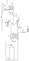
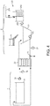
- FIG. 1 illustrates a beverage preparation machine according to the first embodiment of the invention.
- the beverage preparation machine comprises a beverage preparation unit 2 in which the hot beverage is prepared and then cooled.
- the beverage preparation unit 2 comprises a beverage mixing chamber 21 configured for receiving :
- the beverage preparation unit 2 comprises a heat exchanger unit 22 configured for exchanging heat between the hot beverage produced by the beverage mixing chamber 21 and a cooling fluid supplied by a cold generation unit 1.
- the cold generation unit 1 comprises a cooling fluid tank from which cooling fluid, such as cold propylene glycol, is pumped by a pump 12 to be fed in the heat exchanger 22 and then fed back to the cooling fluid tank forming a cooling fluid circuit.
- the illustrated cold generation unit 1 can be replaced by a refrigerated unit like a gas compressor providing the heat exchanger unit 22 with a cold fluid.
- the beverage preparation unit 2 comprises a beverage circuit designed to enable the circulation of the beverage in a loop between the heat exchanger unit 22 and the beverage mixing chamber 21.
- the circuit comprises a pump 23 for circulating the beverage in the beverage circuit.
- the circuit is designed so that hot beverage is pumped from the beverage mixing chamber, preferably at its bottom, and circulated in the heat exchanger 22 to exchange heat with the cooling fluid before being fed back to the mixing chamber 21, preferably at its top.
- the heat exchanger is a plate heat exchanger, the cooling fluid and hot beverage circulating in opposed directions. The circulation happens until the desired temperature is reached for the beverage. Temperature sensor 27 enables the control of said desired temperature.
- the beverage preparation unit 2 comprises two valves 31, 32 for controlling the circulation of the beverage in the beverage preparation unit 2.
- the valve 31 is closed so as to retain the beverage ingredient and hot water a sufficient long period in the chamber to get efficient dissolution.
- the valve 31 is opened and the pump 23 is actuated to circulate the hot beverage to the heat exchanger 22.
- the valve 32 remains closed. After circulation in the heat exchanger and when leaving the heat exchanger, the cooled beverage is fed back to the mixing chamber 21 and, as long as the pump 23 is actuated, the beverage circulates between the chamber and the heat exchanger.
- the pump 12 of the cold generation unit 1 is actuated to feed the cooling fluid to the heat exchanger 22.
- the temperature sensor 27 measures the temperature of the beverage in the circulation loop.
- the pumps 12, 23 are stopped or their speeds are decreased.
- the beverage can be dispensed or can be stored in the mixing chamber or in the heat exchanger or in both devices before the beverage is ordered and dispensed. If the cold beverage is stored in the beverage preparation unit 2 during a long period of time, the pumps 12, 23 can be actuated for short periods of time to keep the beverage sufficiently cold or to avoid that it freezes.
- valves 32 and 31 are opened. The pump 23 can be actuated to push the beverage out of the mixing chamber 21 to the dispensing valve 32.
- a tank Downstream to the valve 32, a tank (not represented) can be positioned to store several prepared beverages and provide a batch of beverages for several beverage dispensing.
- the beverage preparation machine can comprises several other similar beverage preparation units 2 in order to prepare different types of beverages from different sorts of beverage ingredients stored in the storing and dosing containers 24.
- the machine can comprise several tanks downstream to the valves 32 of the several beverage preparation units.
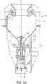
- FIG 2a is a longitudinal section of a beverage mixing chamber 21 that can be used in the beverage preparation machine of Figure 1 .
- the chamber comprises a bowl 211 defining an internal volume.
- the top of the chamber is opened so that beverage ingredient can be introduced therethrough by gravity.
- Hot water is introduced through a water inlet 213 This inlet preferably introduces water at the top of the chamber and along a tangential direction. Alternatively water can be introduced through the top opening of the mixing bowl.
- a centrifugal pump 23 is positioned at the bottom of the chamber. The rotating axis of the centrifugal pump extends along the longitudinal axis XX' of the mixing chamber.
- the impeller 233 of the centrifugal pump is attached to the shaft 232 of a motor 26 and extends along a plane perpendicular to the shaft.
- the body of the chamber designs the casing 231 of the impeller of the centrifugal pump.
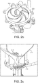
- the blades of the impeller of the centrifugal pump are illustrated in Figure 2b and are designed :
- FIG 4 illustrates a beverage preparation machine such as defined in Figure 1 except that both valves 31, 32 have been replaced by a single three-way valve 33.
- FIG. 5 illustrates a beverage preparation machine according to the second embodiment of the invention.
- the machine comprises the same components as the machine illustrated in Figure 1 except that the machine does not comprise the two valves 31, 32 and that the cold generation unit 1 is not detailed.
- This cold generation unit can be any known technology able to provide a cooling fluid.
- this cold generation unit 1 comprises a refrigeration circuit 13 having a refrigerant circulating therein for generating cold and generally comprising a compressor 131, a condenser 132, an expansion means 133 (expansion valve or capillarity tubes) and an evaporator 134 for treating the refrigerant and corresponding to the heat exchanger 22.
- the machine comprises a selective orienting fluid path 4 at the beverage outlet 221 of the heat exchanger. This selective orienting fluid path 4 supplies the functions of :
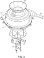
- FIG 6a is a perspective view, respectively a top view, of the beverage mixing chamber 21, the heat exchanger 22 and the pump 23 of the beverage preparation unit that can be implemented in the machine of Figure 5 .
- the chamber comprises a bowl 211 defining an internal volume.
- the top 216 of the chamber is opened so that beverage ingredient and hot water can be introduced therethrough by gravity.
- a centrifugal pump (not visible) is positioned at the bottom of the chamber.
- the rotating axis of the centrifugal pump extends along a longitudinal axis YY' perpendicular to the longitudinal axis XX' of the mixing chamber.
- the axis YY' of the pump is oriented horizontally.
- the impeller of the centrifugal pump is attached to the shaft of a motor 26 and extends along a plane perpendicular to the shaft.
- the body of the chamber designs the casing 231 of the impeller of the centrifugal pump.
- the blades of the impeller of the centrifugal pump (not illustrated) are designed so as to suck the liquid present in the chamber along the axis of the shaft and push said liquid radially to the centrifugal pump outlet 214, when the pump rotates in one first direction (the pumping rotation).
- the centrifugal pump outlet is connected to the heat exchanger 22 via a conduit 28 in order to push the hot beverage inside the heat exchanger.
- the beverage outlet of the heat exchanger is connected to the top opening 216 of the chamber by a selective orienting fluid path 4.
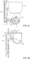
- Figure 6c is a horizontal section of Figure 6b along plane AA showing the conduit 28 linking the centrifugal pump outlet 214 to the heat exchanger 22.
- hot beverage exchanges heat with the cooling fluid circulating along the external sidewall 222 of the heat exchanger.
- Figure 6d is a horizontal section of Figure 6b along plane BB showing the beverage outlet 221 of the heat exchanger unit and the selective orienting fluid path 4.
- This path is designed to guide the beverage either to the bowl 211 of the beverage mixing chamber or to the beverage dispensing outlet depending on the velocity of the beverage.
- this path 4 receives beverage from the beverage outlet 221 of the heat exchanger unit through a beverage inlet 41 connected to the outlet 221 of the heat exchanger unit.
- the path 4 comprises a first beverage outlet 421 connected to the wall of the bowl of the mixing chamber. This first beverage outlet 421 faces the beverage inlet 41.
- a flow of beverage emerging from the beverage outlet 221 of the heat exchanger unit at a relatively high velocity- generally in the form of a jet - is directed in direction of this first beverage outlet 421 and flows in the bowl of the mixing chamber enabling the circulation of the beverage from the heat exchanger to the mixing chamber.
- the path 4 comprises a recess 43 extending downwardly under the space between the beverage inlet 41 and the first beverage outlet 421.
- the path 4 comprises a second beverage outlet 422 positioned at the bottom of said recess.
- a flow of beverage emerging from the beverage outlet 221 of the heat exchanger unit at a relatively low velocity gently falls in the recess 43 of the path and leaves the path through this second beverage outlet 422 at the bottom of the recess.
- This outlet 422 leads to beverage dispensing outlet 29 of the beverage preparation unit.
- the rotation of the centrifugal pump 23 comprised between 10000 and 13000 rpm enables the circulation of the beverage at a velocity sufficient to create a jet of beverage overpassing the recess 43 of the path and reaching the first beverage outlet 421 in the mixing chamber.
- the speed of the rotation of the centrifugal pump 23 can be decreased between 4000 and 6000 rpm and as a result, the beverage emerges from the heat exchanger at a slower velocity so that it falls in the recess 43 and is dispensed through the outlet 29.
- the control of the circulation or dispensing of the beverage depends on the geometry of the path, in particular :
- the configuration of the beverage preparation unit comprising the circuit integrating the heat exchanger unit 22, the beverage mixing chamber 21, the pump, the selective orienting path 4 enables the easy cleaning of the beverage preparation machine without the necessity to dismantle the different parts of the machine.
- Hot water optionally mixed with a cleaning agent, can be introduced in the mixing chamber and circulated in a closed loop by the pump between the mixing chamber and the heat exchanger until the internal parts are cleaned and disinfected.
- the pump is actuated at high speed in order to enable the recirculation of the cleaning solution in the closed loop, then the speed of the pump is decreased in order to evacuate the cleaning solution through the selective orienting path.
- the bowl 21 of the mixing chamber 21, the housing of the pump, a part of the heat exchanger 22 and the path 4 are made of one single piece of material, as illustrated in Figure 6f .
- This embodiment facilitates dismantling of the beverage preparation unit by the operator in view of thorough cleaning or a maintenance operation.
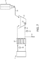
- Figure 7 is an alternative implementation of the beverage preparation machine of Figure 1 wherein the dispensing line 31 of a secondary beverage preparation machine 3 supplies the beverage mixing chamber 21 with hot beverages prepared in the secondary machine. Once the hot beverage is dispensed in the mixing chamber 21, the pumps 23, 12 can be actuated to initiate the cooling of the beverage as explained above in relation with Figure 1 .
- This implementation can be carried out with the beverage preparation machines of Figures 3 and 5 too. Any type of cold generation unit 1 can be used.
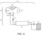
- FIG 8 is a schematic view of a cold generation unit 1 that can be used to provide the cooling fluid in the beverage preparation machines of Figures 1 , 3 and 5 .
- the cold generation unit 1 comprises a refrigeration circuit 13 having a refrigerant circulating therein for generating cold and generally comprising a compressor 131, a condenser 132, an expansion means 133 (expansion valve or capillarity tubes) and an evaporator 134 for treating the refrigerant.
- the evaporator 134 is a heat exchanger enabling the cooling of the cooling fluid circulating in the cooling fluid circuit 15.
- this cooling fluid is propylene glycol.
- the cooling fluid is supplied from a cooling fluid tank 11 by a pump 14 and fed back to the cooling fluid tank 11 once cooled by the heat exchanger 134. Cooling fluid stored in the cooling fluid tank can be supplied by a pump 12 to the heat exchanger 22 in order to cool the hot beverage and then fed back to the cooling fluid tank 11. In an alternative way (not illustrated), the cooling fluid circuit 15 can be suppressed and the refrigerant of the refrigeration circuit 13 can be supplied to the heat exchanger 22 in order to cool the hot beverage and then fed back to the cooling fluid tank 11.
- the invention relates too to beverage preparation machines comprising the combination of each above types of centrifugal pumps (oriented either vertically or horizontally) with both different types of circulating and dispensing means (either controlled through valves (as illustrated in first embodiment) or controlled mechanically (as illustrated in second embodiment)).
- different types of cooling units can be used indifferently with different types of pumps and different types of circulating and dispensing means.
- the beverage preparation machine of the present invention presents the advantage of combining the function of agitation and dissolution of the beverage in preparation and circulation for cooling of said beverage by means of the same pumping device.
- cold generation unit 1 cooling fluid tank 11 pump 12 refrigeration circuit 13 compressor 131 condenser 132 expansion means 133 evaporator 134 pump 14 cooling fluid circuit 15 temperature sensor 16 beverage preparation unit 2 beverage mixing chamber 21 bowl 211 impeller 212 water inlet 213 beverage outlet 214 beverage recirculation inlet 215 top opening 216 heat exchanger 22 heat exchanger beverage outlet 221 external side wall 222 pump 23 casing 231 pump shaft 232 impeller 233 storing and dosing container 24 hot water supply 25 water supply 251 water heating tank 252 pump 253 motor 26 temperature sensor 27 conduit 28 beverage dispensing outlet 29 secondary beverage preparation machine 3 dispensing line 31 valves 31, 32, 33 selective orienting fluid path 4 beverage inlet 41 first beverage outlet 421 second beverage outlet 422 recess 43 beverage tank 5
Landscapes
- Engineering & Computer Science (AREA)
- Food Science & Technology (AREA)
- Apparatus For Making Beverages (AREA)
- Devices For Dispensing Beverages (AREA)
Claims (15)
- Getränkezubereitungsmaschine (10), die zum Zubereiten kalter Getränke aus löslichem Getränkebestandteil und Wasser konfiguriert ist, wobei die Maschine Folgendes umfasst:- eine Kälteerzeugungseinheit (1) zum Zuführen eines Kühlfluids, und- mindestens eine Getränkezubereitungseinheit (2), umfassend:. eine Getränkemischkammer (21), die zum Mischen eines löslichen Getränkebestandteils und heißen Wassers konfiguriert ist, um ein heißes Getränk herzustellen, wobei die Kammer ein Mischlaufrad umfasst, und. eine Wärmetauschereinheit (22), die zum Austauschen von Wärme zwischen dem von der Getränkemischkammer hergestellten Getränk und dem von der Kälteerzeugungseinheit zugeführten Kühlfluid konfiguriert ist, dadurch gekennzeichnet, dass die Maschine ferner Folgendes umfasst:. einen Getränkekreislauf, der die Wärmetauschereinheit (22) und die Getränkemischkammer (21) umfasst, wobei der Kreislauf dazu ausgestaltet ist, die Zirkulation des Getränks in einem geschlossenen Kreis zwischen der Getränkemischkammer und der Wärmetauschereinheit zu ermöglichen, und wobei der Kreislauf eine Pumpe (23) zum Zirkulieren des Getränks in dem Getränkekreislauf umfasst, und. ein Zirkulationsmittel (31, 4), das zum Ermöglichen der Zirkulation des Getränks in dem geschlossenen Kreis zwischen der Getränkemischkammer und der Wärmetauschereinheit ausgelegt ist, und. ein Ausgabemittel (32, 4), das zum Ermöglichen der Ausgabe des Getränks aus dem Getränkekreislauf durch einen Getränkeausgabeauslass ausgelegt ist.
- Getränkezubereitungsmaschine nach Anspruch 1, wobei das Mischlaufrad der Getränkemischkammer die Pumpe (23) zum Zirkulieren des Getränks im Getränkekreislauf ist.
- Getränkezubereitungsmaschine nach Anspruch 2, wobei das Mischlaufrad eine am Boden der Mischkammer positionierte Zentrifugalpumpe ist.
- Getränkezubereitungsmaschine nach Anspruch 3, wobei:- die Mischkammer (21) einen Getränkeauslass (214) umfasst, der senkrecht zur Drehachse der Zentrifugalpumpe ausgerichtet ist, und- der Boden des Kammerkörpers dazu ausgestaltet ist, das Gehäuse (231) der Zentrifugalpumpe (23) zu bilden und das Laufrad (232) der Zentrifugalpumpe zu umgeben.
- Getränkezubereitungsmaschine nach einem der vorstehenden Ansprüche, wobei:- das Zirkulationsmittel (31) ein erstes Ventil ist, wobei das erste Ventil nahe dem Boden der Getränkemischkammer positioniert ist, und- das Ausgabemittel (32) ein zweites Ventil ist, wobei das zweite Ventil nahe dem Boden der Wärmetauschereinheit positioniert ist.
- Getränkezubereitungsmaschine nach einem der Ansprüche 1 bis 4, wobei das Zirkulationsmittel und das Ausgabemittel eine Baugruppe bilden, wobei die Baugruppe aus einem selektiv ausrichtenden Fluidpfad (4) am Getränkeauslass (221) der Wärmetauschereinheit besteht, wobei der Pfad dazu ausgestaltet ist, das Getränk in Abhängigkeit von der Geschwindigkeit des Getränks entweder zu der Getränkemischkammer oder zu dem Getränkeausgabeauslass zu leiten.
- Getränkezubereitungsmaschine nach dem vorstehenden Anspruch, wobei der selektiv ausrichtende Fluidpfad (4) Folgendes umfasst:- einen Getränkeeinlass (41), der mit dem Auslass der Wärmetauschereinheit verbunden ist,- einen ersten Getränkeauslass (421), der mit der Wand der Mischkammer verbunden ist, wobei der erste Getränkeauslass dem Getränkeeinlass zugewandt ist,- eine Aussparung (43), die sich unter dem Raum zwischen dem Getränkeeinlass und dem ersten Getränkeauslass nach unten erstreckt,- einen zweiten Getränkeauslass (422), der am Boden der Aussparung positioniert und mit dem Getränkeausgabeauslass verbunden ist.
- Getränkezubereitungsmaschine nach Anspruch 6 oder 7, wobei:- der Wärmetauscher (22) ein Plattenwärmetauscher ist, wobei der Plattenwärmetauscher mindestens eine Platte umfasst, die mit einem Pfad zur Getränkezirkulation ausgestaltet ist, und- die Platte, der selektiv ausrichtende Fluidpfad und die Mischkammer aus einem einzigen Materialstück gebildet sind.
- Getränkezubereitungsmaschine nach einem der vorstehenden Ansprüche, wobei die Maschine einen Tank (5) zum Aufbewahren des in der Getränkezubereitungseinheit (2) zubereiteten kalten Getränks umfasst und wobei der Getränkeausgabeauslass (29) des Getränkekreislaufs mit dem Tank verbunden ist.
- Getränkezubereitungsmaschine nach einem der vorstehenden Ansprüche, wobei die Getränkezubereitungseinheit (2) Folgendes umfasst:- mindestens einen Behälter (24) zum Aufbewahren und Dosieren eines löslichen Getränkebestandteils, und- eine Heißwasserversorgung (25), und
wobei der Behälter und die Versorgung zum Ausgeben einer Dosis Getränkebestandteils und Wassers in die Getränkemischkammer konfiguriert sind. - Getränkezubereitungsmaschine nach einem der vorstehenden Ansprüche, wobei die Maschine mehrere Getränkezubereitungseinheiten (2) umfasst.
- Getränkezubereitungsmaschine nach einem der Ansprüche 1 bis 9, wobei die Getränkezubereitungseinheit (2) mit einer sekundären Getränkezubereitungsmaschine (3) gekoppelt ist, wobei die sekundäre Maschine Heißgetränke ausgibt und wobei die Heißgetränkeausgabeleitung (31) der sekundären Maschine in die Mischkammer (21) der Getränkezubereitungsmaschine mündet.
- Verfahren zur Zubereitung kalter Getränke aus einem löslichen Getränkebestandteil und Wasser mit einer Getränkezubereitungsmaschine nach einem der Ansprüche 1 bis 12, das die folgenden Schritte umfasst:- Einführen einer Dosis löslichen Getränkebestandteils und heißen Wassers in die Getränkemischkammer, um ein heißes Getränk herzustellen, dann- Zirkulieren des heißen Getränks in dem Kreis zwischen der Wärmetauschereinheit und der Getränkemischkammer und gleichzeitiges Zirkulieren des Kühlfluids in dem Wärmetauscher, bis das Getränk die erforderliche kalte Temperatur erreicht, dann- wahlweise Aufbewahren des kalten Getränks in dem Getränkekreislauf, und- Ausgeben des kalten Getränks, vorzugsweise in einen Tank.
- Verfahren nach dem vorstehenden Anspruch, wobei die Maschine das Zirkulationsmittel und das Ausgabemittel umfasst, die eine Baugruppe bilden, wobei die Baugruppe aus einem selektiv ausrichtenden Fluidpfad (4) am Getränkeauslass der Wärmetauschereinheit besteht, wobei der Pfad dazu ausgestaltet ist, das Getränk in Abhängigkeit von der Geschwindigkeit des Getränks entweder zu der Getränkemischkammer (21) oder zu dem Getränkeausgabeauslass (29) zu leiten, wobei das Verfahren die folgenden Schritte umfasst:- Einführen einer Dosis löslichen Getränkebestandteils und heißen Wassers in die Getränkemischkammer, um ein heißes Getränk herzustellen, und Drehen des Mischlaufrades mit hoher Geschwindigkeit, um das heiße Getränk in dem Kreis zwischen der Wärmetauschereinheit und der Getränkemischkammer zirkulieren zu lassen, bis das Getränk die erforderliche kalte Temperatur erreicht, dann- Drehen des Mischlaufrades mit einer niedrigeren Geschwindigkeit, um das Getränk durch den Getränkeausgabeauslass auszugeben.
- Verfahren zur Reinigung einer Getränkezubereitungsmaschine nach einem der Ansprüche 6 bis 8, das die folgenden Schritte umfasst:- Einführen einer Reinigungsflüssigkeit in die Getränkemischkammer und Drehen des Mischlaufrades mit hoher Geschwindigkeit, um die Reinigungsflüssigkeit in dem Kreis zwischen der Wärmetauschereinheit und der Getränkemischkammer zu zirkulieren, dann- Drehen des Mischlaufrades mit einer niedrigeren Geschwindigkeit, um das Getränk durch den Getränkeausgabeauslass abzulassen.
Applications Claiming Priority (3)
| Application Number | Priority Date | Filing Date | Title |
|---|---|---|---|
| EP16207269 | 2016-12-29 | ||
| EP17194376 | 2017-10-02 | ||
| PCT/EP2017/080361 WO2018121944A1 (en) | 2016-12-29 | 2017-11-24 | Cold beverages preparation machine |
Publications (2)
| Publication Number | Publication Date |
|---|---|
| EP3562359A1 EP3562359A1 (de) | 2019-11-06 |
| EP3562359B1 true EP3562359B1 (de) | 2020-12-23 |
Family
ID=60450677
Family Applications (1)
| Application Number | Title | Priority Date | Filing Date |
|---|---|---|---|
| EP17803960.8A Not-in-force EP3562359B1 (de) | 2016-12-29 | 2017-11-24 | Ausschankvorrichtung für kalte getränke |
Country Status (9)
| Country | Link |
|---|---|
| EP (1) | EP3562359B1 (de) |
| JP (1) | JP7058653B6 (de) |
| CN (1) | CN109982618B (de) |
| AU (1) | AU2017387345B2 (de) |
| BR (1) | BR112019010296B1 (de) |
| MX (1) | MX2019005844A (de) |
| PH (1) | PH12019550082A1 (de) |
| WO (1) | WO2018121944A1 (de) |
| ZA (1) | ZA201903263B (de) |
Families Citing this family (5)
| Publication number | Priority date | Publication date | Assignee | Title |
|---|---|---|---|---|
| EP3826517B1 (de) | 2018-07-24 | 2022-08-31 | Société des Produits Nestlé S.A. | Getränkezubereitungsverfahren |
| GB2578824B (en) * | 2018-10-02 | 2021-03-10 | James Finlay Ltd | A method and apparatus for producing a beverage |
| CN209341677U (zh) * | 2018-12-29 | 2019-09-03 | 张钧胜 | 一种新型液体冷却器 |
| JP7486510B2 (ja) * | 2019-02-25 | 2024-05-17 | ソシエテ・デ・プロデュイ・ネスレ・エス・アー | 低温飲料注出システム |
| IT202100007328A1 (it) * | 2021-03-25 | 2022-09-25 | Simonelli Group Spa | Sistema per l’erogazione del caffè. |
Family Cites Families (11)
| Publication number | Priority date | Publication date | Assignee | Title |
|---|---|---|---|---|
| JPS5912711Y2 (ja) * | 1979-01-11 | 1984-04-16 | 富士電機株式会社 | 飲料自動販売機のミキシング装置 |
| JPH0546148Y2 (de) * | 1987-03-05 | 1993-12-01 | ||
| US4919041A (en) * | 1988-12-22 | 1990-04-24 | Miller Harold F | Brewing and dispensing system and method for iced tea |
| JP3039184B2 (ja) * | 1993-03-18 | 2000-05-08 | 松下電器産業株式会社 | 電気ジャーポット |
| JPH10276738A (ja) * | 1997-03-31 | 1998-10-20 | Sigma Sci Kk | 健康飲料の製造方法 |
| CN2302737Y (zh) * | 1997-07-30 | 1999-01-06 | 赵琦 | 多功能电子冰热饮料器 |
| DE602007001147D1 (de) * | 2007-03-06 | 2009-07-02 | Nestec Sa | System zur Herstellung eines Getränkes aus einer Kapsel und Verfahren |
| DE102008021777A1 (de) * | 2008-04-30 | 2009-11-05 | Eugster/Frismag Ag | Verfahren zur Herstellung eines Getränks sowie Getränkezubereitungsvorrichtung zur Ausübung des Verfahrens |
| IT1403653B1 (it) * | 2011-01-25 | 2013-10-31 | Imper Spa | Macchina erogatrice di bevande calde e fredde |
| US20170035236A1 (en) | 2014-02-28 | 2017-02-09 | Nestec S.A. | Beverage System for Providing a Cold Beverage |
| CH709458B1 (de) * | 2014-04-01 | 2018-06-29 | Schaerer Ag | Kaffeemaschine sowie Verfahren zum Betrieb einer solchen Kaffeemaschine. |
-
2017
- 2017-11-24 EP EP17803960.8A patent/EP3562359B1/de not_active Not-in-force
- 2017-11-24 AU AU2017387345A patent/AU2017387345B2/en active Active
- 2017-11-24 CN CN201780071985.9A patent/CN109982618B/zh active Active
- 2017-11-24 WO PCT/EP2017/080361 patent/WO2018121944A1/en not_active Ceased
- 2017-11-24 BR BR112019010296-5A patent/BR112019010296B1/pt active IP Right Grant
- 2017-11-24 MX MX2019005844A patent/MX2019005844A/es unknown
- 2017-11-24 JP JP2019527128A patent/JP7058653B6/ja not_active Expired - Fee Related
-
2019
- 2019-05-07 PH PH12019550082A patent/PH12019550082A1/en unknown
- 2019-05-23 ZA ZA2019/03263A patent/ZA201903263B/en unknown
Non-Patent Citations (1)
| Title |
|---|
| None * |
Also Published As
| Publication number | Publication date |
|---|---|
| JP7058653B2 (ja) | 2022-04-22 |
| ZA201903263B (en) | 2021-01-27 |
| AU2017387345B2 (en) | 2023-04-13 |
| EP3562359A1 (de) | 2019-11-06 |
| BR112019010296A2 (pt) | 2019-09-03 |
| WO2018121944A1 (en) | 2018-07-05 |
| JP2020503089A (ja) | 2020-01-30 |
| JP7058653B6 (ja) | 2022-08-01 |
| PH12019550082A1 (en) | 2020-02-10 |
| CN109982618B (zh) | 2022-02-08 |
| CN109982618A (zh) | 2019-07-05 |
| BR112019010296B1 (pt) | 2023-04-18 |
| AU2017387345A1 (en) | 2019-05-30 |
| MX2019005844A (es) | 2019-10-02 |
Similar Documents
| Publication | Publication Date | Title |
|---|---|---|
| EP3562359B1 (de) | Ausschankvorrichtung für kalte getränke | |
| US12161250B2 (en) | Beverage apparatus with mixing chamber | |
| US11021319B2 (en) | System for providing a single serving of a frozen confection | |
| US11737595B2 (en) | Beverage preparation device | |
| US20180368612A1 (en) | Rapid heatless extraction of flavors from a soluble substance, method and systems thereof | |
| US11700864B2 (en) | Methods for preparation of gelatin-based products | |
| CN105321263A (zh) | 杯内饮料调制方法 | |
| MXPA04000363A (es) | Sistema para batir una suspension fluida y metodo para el mismo. | |
| JP2004174093A (ja) | ミルクフォーマー、及びこれを用いたコーヒー飲料製造装置 | |
| US20060207433A1 (en) | Beverage preparing method for beverage dispenser and beverage dispenser | |
| EP3826517B1 (de) | Getränkezubereitungsverfahren | |
| US20260083275A1 (en) | Beverage dispenser | |
| JP7221311B2 (ja) | 高温飲料又は冷凍飲料又は氷飲料を製造する装置 | |
| EP3064470A1 (de) | Getränkespender zur herstellung kalter getränke | |
| CN219500842U (zh) | 一种多功能饮品机 | |
| JP2011253460A (ja) | 自動販売機 | |
| JPH0891496A (ja) | 飲料用ディスペンサ |
Legal Events
| Date | Code | Title | Description |
|---|---|---|---|
| STAA | Information on the status of an ep patent application or granted ep patent |
Free format text: STATUS: UNKNOWN |
|
| STAA | Information on the status of an ep patent application or granted ep patent |
Free format text: STATUS: THE INTERNATIONAL PUBLICATION HAS BEEN MADE |
|
| PUAI | Public reference made under article 153(3) epc to a published international application that has entered the european phase |
Free format text: ORIGINAL CODE: 0009012 |
|
| STAA | Information on the status of an ep patent application or granted ep patent |
Free format text: STATUS: REQUEST FOR EXAMINATION WAS MADE |
|
| 17P | Request for examination filed |
Effective date: 20190729 |
|
| AK | Designated contracting states |
Kind code of ref document: A1 Designated state(s): AL AT BE BG CH CY CZ DE DK EE ES FI FR GB GR HR HU IE IS IT LI LT LU LV MC MK MT NL NO PL PT RO RS SE SI SK SM TR |
|
| AX | Request for extension of the european patent |
Extension state: BA ME |
|
| DAV | Request for validation of the european patent (deleted) | ||
| DAX | Request for extension of the european patent (deleted) | ||
| RIN1 | Information on inventor provided before grant (corrected) |
Inventor name: FERRAND, MICKAEL Inventor name: DEMIERRE, JONATHAN Inventor name: MARET, CHARLOTTE Inventor name: CALDERONE, ROBERTO ANGELO Inventor name: CADUFF, MARCO Inventor name: REUST, ALEXIS Inventor name: PINDJUROV, RISTE |
|
| GRAP | Despatch of communication of intention to grant a patent |
Free format text: ORIGINAL CODE: EPIDOSNIGR1 |
|
| STAA | Information on the status of an ep patent application or granted ep patent |
Free format text: STATUS: GRANT OF PATENT IS INTENDED |
|
| INTG | Intention to grant announced |
Effective date: 20200804 |
|
| GRAS | Grant fee paid |
Free format text: ORIGINAL CODE: EPIDOSNIGR3 |
|
| GRAA | (expected) grant |
Free format text: ORIGINAL CODE: 0009210 |
|
| STAA | Information on the status of an ep patent application or granted ep patent |
Free format text: STATUS: THE PATENT HAS BEEN GRANTED |
|
| AK | Designated contracting states |
Kind code of ref document: B1 Designated state(s): AL AT BE BG CH CY CZ DE DK EE ES FI FR GB GR HR HU IE IS IT LI LT LU LV MC MK MT NL NO PL PT RO RS SE SI SK SM TR |
|
| REG | Reference to a national code |
Ref country code: GB Ref legal event code: FG4D |
|
| REG | Reference to a national code |
Ref country code: DE Ref legal event code: R096 Ref document number: 602017030172 Country of ref document: DE |
|
| REG | Reference to a national code |
Ref country code: AT Ref legal event code: REF Ref document number: 1346867 Country of ref document: AT Kind code of ref document: T Effective date: 20210115 |
|
| REG | Reference to a national code |
Ref country code: IE Ref legal event code: FG4D |
|
| PG25 | Lapsed in a contracting state [announced via postgrant information from national office to epo] |
Ref country code: NO Free format text: LAPSE BECAUSE OF FAILURE TO SUBMIT A TRANSLATION OF THE DESCRIPTION OR TO PAY THE FEE WITHIN THE PRESCRIBED TIME-LIMIT Effective date: 20210323 Ref country code: GR Free format text: LAPSE BECAUSE OF FAILURE TO SUBMIT A TRANSLATION OF THE DESCRIPTION OR TO PAY THE FEE WITHIN THE PRESCRIBED TIME-LIMIT Effective date: 20210324 Ref country code: FI Free format text: LAPSE BECAUSE OF FAILURE TO SUBMIT A TRANSLATION OF THE DESCRIPTION OR TO PAY THE FEE WITHIN THE PRESCRIBED TIME-LIMIT Effective date: 20201223 Ref country code: RS Free format text: LAPSE BECAUSE OF FAILURE TO SUBMIT A TRANSLATION OF THE DESCRIPTION OR TO PAY THE FEE WITHIN THE PRESCRIBED TIME-LIMIT Effective date: 20201223 |
|
| REG | Reference to a national code |
Ref country code: AT Ref legal event code: MK05 Ref document number: 1346867 Country of ref document: AT Kind code of ref document: T Effective date: 20201223 |
|
| REG | Reference to a national code |
Ref country code: NL Ref legal event code: MP Effective date: 20201223 |
|
| PG25 | Lapsed in a contracting state [announced via postgrant information from national office to epo] |
Ref country code: LV Free format text: LAPSE BECAUSE OF FAILURE TO SUBMIT A TRANSLATION OF THE DESCRIPTION OR TO PAY THE FEE WITHIN THE PRESCRIBED TIME-LIMIT Effective date: 20201223 Ref country code: SE Free format text: LAPSE BECAUSE OF FAILURE TO SUBMIT A TRANSLATION OF THE DESCRIPTION OR TO PAY THE FEE WITHIN THE PRESCRIBED TIME-LIMIT Effective date: 20201223 Ref country code: BG Free format text: LAPSE BECAUSE OF FAILURE TO SUBMIT A TRANSLATION OF THE DESCRIPTION OR TO PAY THE FEE WITHIN THE PRESCRIBED TIME-LIMIT Effective date: 20210323 |
|
| PG25 | Lapsed in a contracting state [announced via postgrant information from national office to epo] |
Ref country code: HR Free format text: LAPSE BECAUSE OF FAILURE TO SUBMIT A TRANSLATION OF THE DESCRIPTION OR TO PAY THE FEE WITHIN THE PRESCRIBED TIME-LIMIT Effective date: 20201223 Ref country code: NL Free format text: LAPSE BECAUSE OF FAILURE TO SUBMIT A TRANSLATION OF THE DESCRIPTION OR TO PAY THE FEE WITHIN THE PRESCRIBED TIME-LIMIT Effective date: 20201223 |
|
| REG | Reference to a national code |
Ref country code: LT Ref legal event code: MG9D |
|
| PG25 | Lapsed in a contracting state [announced via postgrant information from national office to epo] |
Ref country code: SK Free format text: LAPSE BECAUSE OF FAILURE TO SUBMIT A TRANSLATION OF THE DESCRIPTION OR TO PAY THE FEE WITHIN THE PRESCRIBED TIME-LIMIT Effective date: 20201223 Ref country code: RO Free format text: LAPSE BECAUSE OF FAILURE TO SUBMIT A TRANSLATION OF THE DESCRIPTION OR TO PAY THE FEE WITHIN THE PRESCRIBED TIME-LIMIT Effective date: 20201223 Ref country code: PT Free format text: LAPSE BECAUSE OF FAILURE TO SUBMIT A TRANSLATION OF THE DESCRIPTION OR TO PAY THE FEE WITHIN THE PRESCRIBED TIME-LIMIT Effective date: 20210423 Ref country code: SM Free format text: LAPSE BECAUSE OF FAILURE TO SUBMIT A TRANSLATION OF THE DESCRIPTION OR TO PAY THE FEE WITHIN THE PRESCRIBED TIME-LIMIT Effective date: 20201223 Ref country code: EE Free format text: LAPSE BECAUSE OF FAILURE TO SUBMIT A TRANSLATION OF THE DESCRIPTION OR TO PAY THE FEE WITHIN THE PRESCRIBED TIME-LIMIT Effective date: 20201223 Ref country code: CZ Free format text: LAPSE BECAUSE OF FAILURE TO SUBMIT A TRANSLATION OF THE DESCRIPTION OR TO PAY THE FEE WITHIN THE PRESCRIBED TIME-LIMIT Effective date: 20201223 Ref country code: LT Free format text: LAPSE BECAUSE OF FAILURE TO SUBMIT A TRANSLATION OF THE DESCRIPTION OR TO PAY THE FEE WITHIN THE PRESCRIBED TIME-LIMIT Effective date: 20201223 |
|
| PG25 | Lapsed in a contracting state [announced via postgrant information from national office to epo] |
Ref country code: PL Free format text: LAPSE BECAUSE OF FAILURE TO SUBMIT A TRANSLATION OF THE DESCRIPTION OR TO PAY THE FEE WITHIN THE PRESCRIBED TIME-LIMIT Effective date: 20201223 Ref country code: AT Free format text: LAPSE BECAUSE OF FAILURE TO SUBMIT A TRANSLATION OF THE DESCRIPTION OR TO PAY THE FEE WITHIN THE PRESCRIBED TIME-LIMIT Effective date: 20201223 |
|
| REG | Reference to a national code |
Ref country code: DE Ref legal event code: R097 Ref document number: 602017030172 Country of ref document: DE |
|
| PG25 | Lapsed in a contracting state [announced via postgrant information from national office to epo] |
Ref country code: IS Free format text: LAPSE BECAUSE OF FAILURE TO SUBMIT A TRANSLATION OF THE DESCRIPTION OR TO PAY THE FEE WITHIN THE PRESCRIBED TIME-LIMIT Effective date: 20210423 |
|
| PG25 | Lapsed in a contracting state [announced via postgrant information from national office to epo] |
Ref country code: AL Free format text: LAPSE BECAUSE OF FAILURE TO SUBMIT A TRANSLATION OF THE DESCRIPTION OR TO PAY THE FEE WITHIN THE PRESCRIBED TIME-LIMIT Effective date: 20201223 Ref country code: IT Free format text: LAPSE BECAUSE OF FAILURE TO SUBMIT A TRANSLATION OF THE DESCRIPTION OR TO PAY THE FEE WITHIN THE PRESCRIBED TIME-LIMIT Effective date: 20201223 |
|
| PLBE | No opposition filed within time limit |
Free format text: ORIGINAL CODE: 0009261 |
|
| STAA | Information on the status of an ep patent application or granted ep patent |
Free format text: STATUS: NO OPPOSITION FILED WITHIN TIME LIMIT |
|
| PG25 | Lapsed in a contracting state [announced via postgrant information from national office to epo] |
Ref country code: DK Free format text: LAPSE BECAUSE OF FAILURE TO SUBMIT A TRANSLATION OF THE DESCRIPTION OR TO PAY THE FEE WITHIN THE PRESCRIBED TIME-LIMIT Effective date: 20201223 |
|
| 26N | No opposition filed |
Effective date: 20210924 |
|
| PG25 | Lapsed in a contracting state [announced via postgrant information from national office to epo] |
Ref country code: ES Free format text: LAPSE BECAUSE OF FAILURE TO SUBMIT A TRANSLATION OF THE DESCRIPTION OR TO PAY THE FEE WITHIN THE PRESCRIBED TIME-LIMIT Effective date: 20201223 |
|
| PG25 | Lapsed in a contracting state [announced via postgrant information from national office to epo] |
Ref country code: SI Free format text: LAPSE BECAUSE OF FAILURE TO SUBMIT A TRANSLATION OF THE DESCRIPTION OR TO PAY THE FEE WITHIN THE PRESCRIBED TIME-LIMIT Effective date: 20201223 |
|
| PG25 | Lapsed in a contracting state [announced via postgrant information from national office to epo] |
Ref country code: IS Free format text: LAPSE BECAUSE OF FAILURE TO SUBMIT A TRANSLATION OF THE DESCRIPTION OR TO PAY THE FEE WITHIN THE PRESCRIBED TIME-LIMIT Effective date: 20210423 |
|
| REG | Reference to a national code |
Ref country code: DE Ref legal event code: R119 Ref document number: 602017030172 Country of ref document: DE |
|
| PG25 | Lapsed in a contracting state [announced via postgrant information from national office to epo] |
Ref country code: MC Free format text: LAPSE BECAUSE OF FAILURE TO SUBMIT A TRANSLATION OF THE DESCRIPTION OR TO PAY THE FEE WITHIN THE PRESCRIBED TIME-LIMIT Effective date: 20201223 |
|
| REG | Reference to a national code |
Ref country code: CH Ref legal event code: PL |
|
| GBPC | Gb: european patent ceased through non-payment of renewal fee |
Effective date: 20211124 |
|
| PG25 | Lapsed in a contracting state [announced via postgrant information from national office to epo] |
Ref country code: LU Free format text: LAPSE BECAUSE OF NON-PAYMENT OF DUE FEES Effective date: 20211124 Ref country code: BE Free format text: LAPSE BECAUSE OF NON-PAYMENT OF DUE FEES Effective date: 20211130 |
|
| REG | Reference to a national code |
Ref country code: BE Ref legal event code: MM Effective date: 20211130 |
|
| PG25 | Lapsed in a contracting state [announced via postgrant information from national office to epo] |
Ref country code: IE Free format text: LAPSE BECAUSE OF NON-PAYMENT OF DUE FEES Effective date: 20211124 Ref country code: GB Free format text: LAPSE BECAUSE OF NON-PAYMENT OF DUE FEES Effective date: 20211124 Ref country code: DE Free format text: LAPSE BECAUSE OF NON-PAYMENT OF DUE FEES Effective date: 20220601 |
|
| PG25 | Lapsed in a contracting state [announced via postgrant information from national office to epo] |
Ref country code: FR Free format text: LAPSE BECAUSE OF NON-PAYMENT OF DUE FEES Effective date: 20211130 |
|
| PG25 | Lapsed in a contracting state [announced via postgrant information from national office to epo] |
Ref country code: CY Free format text: LAPSE BECAUSE OF FAILURE TO SUBMIT A TRANSLATION OF THE DESCRIPTION OR TO PAY THE FEE WITHIN THE PRESCRIBED TIME-LIMIT Effective date: 20201223 |
|
| PG25 | Lapsed in a contracting state [announced via postgrant information from national office to epo] |
Ref country code: LI Free format text: LAPSE BECAUSE OF NON-PAYMENT OF DUE FEES Effective date: 20220701 Ref country code: HU Free format text: LAPSE BECAUSE OF FAILURE TO SUBMIT A TRANSLATION OF THE DESCRIPTION OR TO PAY THE FEE WITHIN THE PRESCRIBED TIME-LIMIT; INVALID AB INITIO Effective date: 20171124 Ref country code: CH Free format text: LAPSE BECAUSE OF NON-PAYMENT OF DUE FEES Effective date: 20220701 |
|
| PG25 | Lapsed in a contracting state [announced via postgrant information from national office to epo] |
Ref country code: MK Free format text: LAPSE BECAUSE OF FAILURE TO SUBMIT A TRANSLATION OF THE DESCRIPTION OR TO PAY THE FEE WITHIN THE PRESCRIBED TIME-LIMIT Effective date: 20201223 |
|
| PG25 | Lapsed in a contracting state [announced via postgrant information from national office to epo] |
Ref country code: TR Free format text: LAPSE BECAUSE OF FAILURE TO SUBMIT A TRANSLATION OF THE DESCRIPTION OR TO PAY THE FEE WITHIN THE PRESCRIBED TIME-LIMIT Effective date: 20201223 |
|
| PG25 | Lapsed in a contracting state [announced via postgrant information from national office to epo] |
Ref country code: MT Free format text: LAPSE BECAUSE OF FAILURE TO SUBMIT A TRANSLATION OF THE DESCRIPTION OR TO PAY THE FEE WITHIN THE PRESCRIBED TIME-LIMIT Effective date: 20201223 |