EP3561998A1 - Nabendynamo - Google Patents
Nabendynamo Download PDFInfo
- Publication number
- EP3561998A1 EP3561998A1 EP17883171.5A EP17883171A EP3561998A1 EP 3561998 A1 EP3561998 A1 EP 3561998A1 EP 17883171 A EP17883171 A EP 17883171A EP 3561998 A1 EP3561998 A1 EP 3561998A1
- Authority
- EP
- European Patent Office
- Prior art keywords
- yoke
- magnetic pole
- outer circumferential
- circumferential side
- coil
- Prior art date
- Legal status (The legal status is an assumption and is not a legal conclusion. Google has not performed a legal analysis and makes no representation as to the accuracy of the status listed.)
- Withdrawn
Links
Images










Classifications
-
- H—ELECTRICITY
- H02—GENERATION; CONVERSION OR DISTRIBUTION OF ELECTRIC POWER
- H02K—DYNAMO-ELECTRIC MACHINES
- H02K21/00—Synchronous motors having permanent magnets; Synchronous generators having permanent magnets
- H02K21/12—Synchronous motors having permanent magnets; Synchronous generators having permanent magnets with stationary armatures and rotating magnets
- H02K21/22—Synchronous motors having permanent magnets; Synchronous generators having permanent magnets with stationary armatures and rotating magnets with magnets rotating around the armatures, e.g. flywheel magnetos
- H02K21/227—Synchronous motors having permanent magnets; Synchronous generators having permanent magnets with stationary armatures and rotating magnets with magnets rotating around the armatures, e.g. flywheel magnetos having an annular armature coil
-
- B—PERFORMING OPERATIONS; TRANSPORTING
- B62—LAND VEHICLES FOR TRAVELLING OTHERWISE THAN ON RAILS
- B62J—CYCLE SADDLES OR SEATS; AUXILIARY DEVICES OR ACCESSORIES SPECIALLY ADAPTED TO CYCLES AND NOT OTHERWISE PROVIDED FOR, e.g. ARTICLE CARRIERS OR CYCLE PROTECTORS
- B62J6/00—Arrangement of optical signalling or lighting devices on cycles; Mounting or supporting thereof; Circuits therefor
- B62J6/06—Arrangement of lighting dynamos or drives therefor
- B62J6/12—Dynamos arranged in the wheel hub
-
- H—ELECTRICITY
- H02—GENERATION; CONVERSION OR DISTRIBUTION OF ELECTRIC POWER
- H02K—DYNAMO-ELECTRIC MACHINES
- H02K1/00—Details of the magnetic circuit
- H02K1/06—Details of the magnetic circuit characterised by the shape, form or construction
- H02K1/12—Stationary parts of the magnetic circuit
- H02K1/14—Stator cores with salient poles
- H02K1/145—Stator cores with salient poles having an annular coil, e.g. of the claw-pole type
-
- H—ELECTRICITY
- H02—GENERATION; CONVERSION OR DISTRIBUTION OF ELECTRIC POWER
- H02K—DYNAMO-ELECTRIC MACHINES
- H02K7/00—Arrangements for handling mechanical energy structurally associated with dynamo-electric machines, e.g. structural association with mechanical driving motors or auxiliary dynamo-electric machines
- H02K7/18—Structural association of electric generators with mechanical driving motors, e.g. with turbines
- H02K7/1807—Rotary generators
- H02K7/1846—Rotary generators structurally associated with wheels or associated parts
Definitions
- the present invention relates to a hub dynamo.
- a hub dynamo is equipped with a rotor having a permanent magnet on a wheel side. Then, when the rotor rotates around a stator provided on a hub axle side, a coil provided in the stator generates electric power.
- stator in the hub dynamo a stator in which a plurality of first yokes and a plurality of second yokes are respectively disposed on one axial side and the other axial side of a coil bobbin around which a coil is wound is known.
- a claw-pole type in which first yokes and second yokes are assembled to a coil bobbin such that a first yoke outer circumferential side magnetic pole part (teeth part) and a second yoke outer circumferential side magnetic pole part (teeth part) are alternately aligned in a circumferential direction is known.
- each of a first yoke and a second yoke is formed as a laminated yoke in which a plurality of flat plate-shaped members made of a magnetic material are laminated in a direction perpendicular to a radial direction of a coil.
- Each yoke has a C shape when seen at a side view.
- the first yoke has a C shape in a side view having an outer circumferential side magnetic pole part, an inner circumferential side magnetic pole part, and a connecting part.
- the outer circumferential side magnetic pole part is positioned on an outer circumferential side of the coil and a distal end thereof reaches from one axial end side to the other axial end side of the coil.
- the inner circumferential side magnetic pole part is positioned on an inner circumferential side of the coil and a distal end thereof reaches from one axial end side to an intermediate position toward the other axial end side of the coil.
- the connecting part linearly extends in a radial direction at one axial end side of the coil and connects base ends of the outer circumferential side magnetic pole part and the inner circumferential side magnetic pole part.
- the second yoke has a C shape in a side view having an outer circumferential side magnetic pole part, an inner circumferential side magnetic pole part, and a connecting part.
- the outer circumferential side magnetic pole part is positioned on an outer circumferential side of the coil and a distal end thereof reaches from the other axial end side to one axial end side of the coil.
- the inner circumferential side magnetic pole part is positioned on an inner circumferential side of the coil and a distal end thereof reaches from the other axial end side to an intermediate position toward one axial end side of the coil.
- the connecting part linearly extends in the radial direction at the other axial end side of the coil and connects base ends of the outer circumferential side magnetic pole part and the inner circumferential side magnetic pole part.
- the distal end of the inner circumferential side magnetic pole part of the first yoke and the distal end of the inner circumferential side magnetic pole part of the second yoke are brought into contact with each other on the inner circumferential side of the coil. Thereby, the first yoke and the second yoke are magnetically connected.
- the first yoke and the second yoke are alternately aligned in the circumferential direction and are disposed radially in the radial direction when viewed from a center of the coil. Accordingly, positions of the inner circumferential side magnetic pole parts of the first yoke and second yoke adjacent to each other are deviated from each other in the circumferential direction. Therefore, even when the inner circumferential side magnetic pole parts of the first yoke and the second yoke are disposed close to each other in the circumferential direction, the distal end of the inner circumferential side magnetic pole part of one first yoke comes into bridging contact with the distal ends of the inner circumferential side magnetic pole parts of two second yokes adjacent thereto.
- the distal end of the inner circumferential side magnetic pole part of one second yoke comes into bridging contact with the distal ends of the inner circumferential side magnetic pole parts of two first yokes adjacent thereto. That is, the inner circumferential side magnetic pole part of the first yoke and the inner circumferential side magnetic pole part of the second yoke come into contact with each other in a one-to-two relationship.
- Patent Literature 1 Japanese Patent No. 5357937
- the distal end of the inner circumferential side magnetic pole part of the first yoke comes into contact only with a distal end of the inner circumferential side magnetic pole part of one of the second yokes having a longer insertion direction dimension and does not come into contact with a distal end of the inner circumferential side magnetic pole part of the other second yoke, and thus a gap may be formed between the distal end of the inner circumferential side magnetic pole part of the first yoke and the distal end of the inner circumferential side magnetic pole part of the other second yoke.
- iron loss of the yoke may increase and the performance may deteriorate.
- the present invention provides a hub dynamo in which a dimensional variation of yokes can be absorbed so that a gap on a contact surface between the yokes is not formed, thereby improving the performance.
- a hub dynamo includes a rotor having a hub shell rotating together with a wheel, and a permanent magnet circumferentially disposed in an inner circumference of a body part of the hub shell, and a stator which is non-rotatably fixed to a hub axle rotatably supporting the wheel, disposed on an inner circumferential side of the permanent magnet in a state of being accommodated inside the hub shell, and including a ring-shaped coil that outputs an alternating current due to rotation of the rotor, in which the stator includes a plurality of first yokes and a plurality of second yokes as a stator core disposed on one axial side and the other axial side to surround the ring-shaped coil, radially disposed at intervals in a circumferential direction, and alternately disposed in the circumferential direction, in which each of the first yokes includes an outer circumferential side magnetic pole part which is positioned on an outer circumferential side of the coil and
- the yoke is disposed not on a plane in the radial direction but on a plane inclined with respect to the radial direction (actual disposition plane of the yoke). Therefore, the inner circumferential side magnetic pole part of the first yoke and the inner circumferential side magnetic pole part of the second yoke can be brought into contact with each other in a one-to-one relationship. Accordingly, a gap formed on a contact surface between the first yoke and the second yoke due to a variation caused by a dimensional tolerance or the like of the yokes can be eliminated, and a degree of close contact of the contact surface can be increased. As a result, magnetic connection of the yokes can be stabilized and thus iron loss can be reduced.
- connection between the first yoke and the second yoke can be made in a one-to-one relationship, when an output is adjusted downward from a 100% state to, for example, 75%, 50%, or 25%, the number of first yokes and second yokes need only be reduced by an equivalent number. Therefore, the number of required yokes can be reduced.
- the stator may include a coil bobbin made of a non-magnetic material, in which the coil bobbin may have a cylindrical body part around which the coil is wound, and a first flange and a second flange provided on outer circumferences of both axial ends of the body part, a guide part with which one axial end portion of the first yoke is engaged to position the first yoke on the first yoke actual disposition plane may be provided on the first flange, and a guide part with which the other axial end portion of the second yoke is engaged to position the second yoke on the second yoke actual disposition plane may be provided on the second flange.
- the first yoke when one axial end portion of the first yoke is engaged with the guide part of the first flange of the coil bobbin, the first yoke can be positioned on the first yoke actual disposition plane. Also, when one axial end portion of the second yoke is engaged with the guide part of the second flange of the coil bobbin, the second yoke can be positioned on the second yoke actual disposition plane. Accordingly, when the first yoke and the second yoke are assembled to the coil bobbin, a positional relationship between the coil wound around the coil bobbin and the yokes can be appropriately determined.
- the guide part may include a first yoke connecting part guide groove provided on an axial end portion of the first flange and to which the connecting part of the first yoke is fitted so that the first yoke is positioned on the first yoke actual disposition plane, and a second yoke connecting part guide groove provided on an axial end portion of the second flange and to which the connecting part of the second yoke is fitted so that the second yoke is positioned on the second yoke actual disposition plane.
- the yokes when the connecting parts of the yokes are respectively fitted to the first yoke connecting part guide groove and the second yoke connecting part guide groove provided at the axial end portions of the coil bobbin, the yokes can be assembled to the coil bobbin while positioning the yokes appropriately.
- the guide part may include a first yoke outer circumferential side guide groove provided on an outer circumferential surface of the first flange and to which the outer circumferential side magnetic pole part of the first yoke is fitted so that the first yoke is positioned on the first yoke actual disposition plane, and a second yoke outer circumferential side guide groove provided on an outer circumferential surface of the second flange and to which the outer circumferential side magnetic pole part of the second yoke is fitted so that the second yoke is positioned on the second yoke actual disposition plane.
- the yokes when the outer circumferential side magnetic pole parts of the yokes are respectively fitted to the first yoke outer circumferential side guide groove and the second yoke outer circumferential side guide groove provided on the outer circumferential surfaces of the coil bobbin, the yokes can be assembled to the coil bobbin while positioning the yokes appropriately.
- a position of an outer circumferential end in the radial direction of the laminated plate-shaped member positioned on a rear side in the inclination direction of each of the first yoke and the second yoke may protrude outward in the radial direction with respect to a position of an outer circumferential end in the radial direction of the laminated plate-shaped member positioned on a front side in the inclination direction of each of the first yoke and the second yoke.
- a gap (air gap) between an outer circumferential edge of each of the first yoke and the second yoke (outer circumferential edge of the outer circumferential side magnetic pole part of each yoke) laminated with a plurality of plate-shaped members and an inner circumferential surface of the permanent magnet can be made uniform.
- a position of the outer circumferential end in the radial direction of the laminated plate-shaped member positioned on the rear side in the inclination direction of the yokes is formed to be recessed toward a radial inner side with respect to a position of the outer circumferential end in the radial direction of the laminated plate-shaped member positioned on the front side in the inclination direction.
- a gap (air gap) between the outer circumferential end in the radial direction of the laminated plate-shaped member and an inner circumference of the permanent magnet at a position on the rear side in the inclination direction is larger than a gap (air gap) between the outer circumferential end in the radial direction of the laminated plate-shaped member and the inner circumference of the permanent magnet at a position on the front side in the inclination direction, and thus a deviation occurs between the air gaps.
- the position of the outer circumferential end in the radial direction of the laminated plate-shaped member positioned on the rear side in the inclination direction of each yoke is caused to protrude outward in the radial direction with respect to the position of the outer circumferential end in the radial direction of the laminated plate-shaped member positioned on the front side in the inclination direction of each yoke. That is, a dimension of the outer circumferential edge of the yoke on a surface facing the permanent magnet is adjusted. Thereby, the gap (air gap) between the outer circumferential edges of each yoke and the inner circumferential surface of the permanent magnet can be made uniform. As a result, power generation efficiency can be improved.
- a method of making a position of the outer circumferential end in the radial direction of the laminated plate-shaped member positioned on the rear side in the inclination direction of each yoke protrude outward in the radial direction with respect to a position of the outer circumferential end in the radial direction of the laminated plate-shaped members positioned on the front side in the inclination direction of each yoke a method in which dimensions of the plate-shaped members laminated on the front side and the rear side in the inclination direction are made different can be employed.
- a method can be employed in which lamination positions of the plate-shaped members laminated on the front side and the rear side in the inclination direction are deviated.
- a notch part may be provided on at least one of one end side and the other end side in the circumferential direction of an inner circumferential end of the first yoke and the second yoke to avoid interference with an inner circumferential end of another first yoke and second yoke adjacent thereto in the circumferential direction.
- the yokes can be disposed close to each other in the circumferential direction. That is, when the yokes are radially disposed, the inner circumferential parts of adjacent yokes interfere with each other, and the number of disposed yokes may be restricted. Therefore, when the notch part for avoiding the interference as described above is provided, the number of disposed yokes can be increased.
- the yoke is disposed not on a plane in the radial direction but on a plane inclined with respect to the radial direction (actual disposition plane of the yoke). Therefore, the inner circumferential side magnetic pole part of the first yoke and the inner circumferential side magnetic pole part of the second yoke can be brought into contact with each other in a one-to-one relationship. Accordingly, a gap formed on a contact surface between the first yoke and the second yoke due to a variation caused by a dimensional tolerance or the like of the yokes can be eliminated, and thereby a degree of close contact of the contact surface can be increased.
- the present invention can contribute to weight reduction and reduction in costs of the hub dynamo.
- Fig. 1 is a schematic attachment view of a hub dynamo 10.
- the hub dynamo 10 according to the present invention is attached to a hub axle 11 of a bicycle 1 and supplies electric power to a headlamp 4 of the bicycle 1
- a lamp a filament type bulb is not used, and an LED lamp is used for this headlamp 4.
- a front wheel 5 of the bicycle 1 is rotatably supported by a front fork 3 constituting a portion of a frame via a hub axle 11. Both sides of the hub axle 11 are non-rotatably fastened and fixed to the front fork 3 by a nut (not illustrated) or the like.
- the hub dynamo 10 is coaxially attached to the hub axle 11 over a major portion thereof at a center in an axial direction of the hub axle 11.
- the hub dynamo 10 is provided to supply electric power to the headlamp 4 disposed on a side of the front wheel 5.
- the hub dynamo 10 includes a rotor 20 (to be described below) and a stator 101 (to be described below).
- the rotor 20 is connected to spokes 2 of the front wheel 5 and rotates together with the front wheel 5 around the hub axle 11.
- the stator 101 is non-rotatably attached to the hub axle 11 in a state of being positioned on an inner circumferential side of the rotor 20.
- an axial direction of a central axis O of the hub axle 11 is simply referred to as an axial direction
- a direction perpendicular to the axial direction is referred to as a radial direction
- a direction around the central axis O is referred to as a circumferential direction.
- a male screw part (not illustrated) for fixing the hub dynamo 10 to the front fork 3 is formed at a portion of the hub axle 11 on an outer side in the axial direction with respect to a portion in which at least the stator 101 (to be described below) is attached.
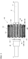
- Fig. 2 is a side view of the hub dynamo 10.
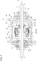
- Fig. 3 is a cross-sectional view of the hub dynamo 10.
- the rotor 20 is constituted mainly by a hub shell 30.
- the hub shell 30 includes a second end plate 33 and a first end plate 32.
- the second end plate 33 is disposed at a cylindrical body part (cylinder part) 31 integrally molded as a substantially bottomed cylindrical shape and on the other axial side Q (right side in Fig. 3 ) of the cylinder part 31.
- the first end plate 32 closes an opening on one axial side P of the body part 31 (left side in Fig. 3 ).
- the first end plate 32 is press-fitted and fixed to the body part 31.
- a flange part 34 protruding toward a radial outer side is formed on an outer circumference on one axial side P and the other axial side Q of the hub shell 30.
- a plurality of support holes 34a penetrating in the axial direction are formed at regular intervals in the circumferential direction in each flange part 34.
- inner end portions of the plurality of spokes 2 extending from a rim 5a of the front wheel 5 to an inner diameter side are engaged with the support holes 34a.
- the support holes 34a of the left and right flange parts 34 are disposed in a phase-shifted manner in the circumferential direction at a half pitch.
- Outer rings of bearings (axle bearing) 35 and 36 are respectively fitted to inner circumferences of the first end plate 32 and the second end plate 33.
- the rotor 20 mainly constituted by the hub shell 30 is rotatably supported by the hub axle 11 via the bearings 35 and 36. Thereby, the rotor 20 rotates around the hub axle 11 together with rotation of the front wheel 5. That is, the rotor 20 functions as a hub that rotatably supports the front wheel 5.
- a permanent magnet 22 formed of, for example, ferrite or the like is disposed on an inner circumference of the body part 31 of the hub shell 30 with a cylindrical ring yoke 21 therebetween.
- the ring yoke 21 is made of a magnetic metal material (for example, iron).
- the hub shell 30 can be made of aluminum to reduce a weight.
- the permanent magnet 22 is disposed in a state of being in close contact with an inner circumference of the ring yoke 21.
- the permanent magnet 22 is affixed with an adhesive or the like. When the permanent magnet 22 is disposed in a cylindrical shape along an inner circumferential surface of the body part 31, the permanent magnet 22 covers the entire outer circumferential surface of the stator 101.
- the permanent magnet 22 is incorporated in the inner circumference of the body part 31 of the hub shell 30 in a state in which it is divided into a plurality of sections in the circumferential direction.
- N pole and S pole magnetic poles are alternately magnetized at regular intervals in the circumferential direction.
- the permanent magnet 22 faces outer circumferential portions of a first yoke 120A and a second yoke 120B to be described below.
- a large-diameter portion is formed at an intermediate portion in the axial direction of the hub axle 11.
- the stator 101 is attached to an outer circumference of the large-diameter portion. As illustrated in Figs. 3 to 5 , the stator 101 is positioned and fixed to the hub axle 11 by a sleeve nut 42 and a fastening nut 44 via plate members 41 and 43 disposed at both axial end portions thereof.
- the hub axle 11, the stator 101, and the like constitute a stator unit 100.
- An inner ring of one side bearing 35 is fitted to an outer circumference of the sleeve nut 42 disposed on one axial side P of the stator unit 100.
- a connector 50 is provided on an outer side of the bearing 35 in the axial direction.
- a nut 51 is disposed on an outer side of the connector 50 in the axial direction.
- Another sleeve nut 45 is disposed on the other axial side Q of the hub axle 11.
- An inner ring of the other side bearing 36 is fitted to an outer circumference of the sleeve nut 45.
- a cover 46 is provided on an outer side of the bearing 36 in the axial direction.
- a nut 47 is disposed on an inner circumferential portion of the cover 46.
- Fig. 6 is a perspective view illustrating a configuration of the stator 101.
- Fig. 7 is an exploded perspective view illustrating a configuration of the stator 101.
- the stator 101 is constituted by a cylindrical coil bobbin 110, a ring-shaped coil 140, and a claw-pole type stator core 120.
- the coil bobbin 110 is made of a synthetic resin (made of a non-magnetic material) through which the hub axle 11 is inserted.
- the coil 140 is wound around the coil bobbin 110.
- the stator core 120 is assembled to surround the coil 140 inside.
- the hub axle 11, the coil bobbin 110, the first yoke 120A, and the second yoke 120B are coaxially disposed.
- a plurality of first yokes 120A are disposed on one axial side P.
- a plurality of second yokes 120B are disposed on the other axial side Q.
- the plurality of first yokes 120A and the plurality of second yokes 120B are radially disposed at regular intervals in the circumferential direction and are alternately disposed to be aligned in the circumferential direction.
- the outer circumferential portion of each of the yokes 120A and 120B is configured to face an inner circumferential surface 22a (see Fig. 3 ) of the permanent magnet 22 with a slight gap (air gap) therebetween.
- the number of the yokes 120A and 120B may be in relation to the number of magnetic poles of the permanent magnet 22. In the present embodiment, a total of 32 pieces including 16 pieces of the first yokes 120A and 16 pieces of the second yokes 120B are provided at regular intervals. Although not illustrated, a wiring is connected to the coil 140. The wiring is drawn out to the outside along the hub axle 11.
- Fig. 8 is a perspective view of the coil bobbin.
- Fig. 9 is a perspective view illustrating a state in which the coil is wound around the coil bobbin.
- the coil bobbin 110 includes a body part 111, a first flange 112A, and a second flange 112B.
- the coil 140 is wound around an outer circumference of the body part 111.
- the first flange 112A and the second flange 112B are each provided to protrude toward a radial outer side on an outer circumference of an end portion on one axial side P and on the other axial side Q of the body part 111.
- a guide groove 113A is provided on an outer end surface in the axial direction of the first flange 112A.
- An engaging groove 114A communicating with the guide groove 113A is provided on an outer circumferential surface of the first flange 112A at a position corresponding to the guide groove 113A.
- the guide groove 113A and the engaging groove 114A are for positioning and attaching the first yoke 120A to the coil bobbin 110.
- a guide groove 113B is provided on an outer end surface in the axial direction of the second flange 112B.
- An engaging groove 114B communicating with the guide groove 113B is provided on an outer circumferential surface of the second flange 112B at a position corresponding to the guide groove 113B.
- the guide groove 113B and the engaging groove 114B are for positioning and attaching the second yoke 120B to the coil bobbin 110.
- support grooves 115A and 115B respectively positioned in the middle of the engaging grooves 114A and in the middle of the engaging grooves 114B in the circumferential direction and configured to respectively support distal ends of the second yoke 120B and the first yoke 120A on the opposite side are provided.
- a circumferential position of the engaging groove 114A of the first flange 112A matches a circumferential position of the support groove 115B of the second flange 112B
- a circumferential position of the engaging groove 114B of the second flange 112B matches a circumferential position of the support groove 115A of the first flange 112A. Details of the guide grooves 113A and 113B, the engaging grooves 114A and 114B, the support grooves 115A and 115B will be described below.
- Fig. 10 is a perspective half-sectional view of the stator.
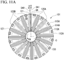
- Fig. 11A is a view of the stator from an axial direction and is a view taken in a direction of arrow EA of Fig. 6 .
- Fig. 11B is a view of the stator from an axial direction and is a view taken in a direction of arrow EB of Fig. 6 .
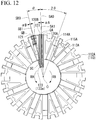
- Fig. 12 is a view of one pair of the yokes and the coil bobbin from an axial direction for explaining a disposition angle of the first yoke and the second yoke of the stator.
- Fig. 11A is a view of the stator from an axial direction and is a view taken in a direction of arrow EA of Fig. 6 .
- Fig. 11B is a view of the stator from an axial direction and is a view taken in a direction of arrow EB of Fig. 6 .
- Fig. 12 is a view of one pair
- FIG. 13A is a view for explaining a disposition angle of the first yoke and the second yoke and is a perspective view illustrating a state before the first yoke and the second yoke are combined.
- Fig. 13B is a view for explaining a disposition angle of the first yoke and the second yoke and is a perspective view illustrating a state after the first yoke and the second yoke are combined.
- Fig. 13C is a view for explaining a disposition angle of the first yoke and the second yoke and is a view taken in a direction of arrow F of Fig. 13B .
- Fig. 13A is a view for explaining a disposition angle of the first yoke and the second yoke and is a perspective view illustrating a state before the first yoke and the second yoke are combined.
- Fig. 13B is a view for explaining a disposition angle of the first yoke and the second
- FIG. 14A is a view for explaining a configuration of each yoke and is a perspective view of one sheet of a plate-shaped member constituting the yoke.
- Fig. 14B is a view for explaining a configuration of each yoke and is a perspective view of the yoke formed by laminating the plate-shaped members.
- Fig. 14C is a view for explaining a configuration of each yoke and is a perspective view of the yoke from a connecting part side.
- the first yoke 120A and the second yoke 120B have the same structure and are formed in a C shape in a side view except that respective directions of assembly with respect to the coil bobbin 110 are opposite to each other.
- the first yoke 120A includes an outer circumferential side magnetic pole part 121, an inner circumferential side magnetic pole part 123, and a connecting part 122.
- the outer circumferential side magnetic pole part 121 is positioned on an outer circumference side of the coil 140 and a distal end thereof reaches from one axial end side (P side) to the other axial end side (Q side) of the coil 140.
- the inner circumferential side magnetic pole part 123 is positioned on an inner circumference side of the coil 140 and a distal end 123a reaches from one axial end side (P side) to an intermediate position toward the other axial end side (Q side) of the coil 140.
- the connecting part 122 linearly extends in the radial direction at one axial end side (P side) of the coil 140 and connects base ends of the outer circumferential side magnetic pole part 121 and the inner circumferential side magnetic pole part 123.
- the second yoke 120B includes an outer circumferential side magnetic pole part 121, an inner circumferential side magnetic pole part 123, and a connecting part 122.
- the outer circumferential side magnetic pole part 121 is positioned on the outer circumference side of the coil 140 and a distal end thereof reaches from the other axial end side (Q side) to one axial end side (P side) of the coil 140.
- the inner circumferential side magnetic pole part 123 is positioned on an inner circumference side of the coil 140 and a distal end thereof reaches from the other axial end side (Q side) to an intermediate position toward one axial end side (P side) of the coil 140.
- the connecting part 122 linearly extends in the radial direction at the other axial end side (Q side) of the coil 140 and connects base ends of the outer circumferential side magnetic pole part 121 and the inner circumferential side magnetic pole part 123.
- a radial outer circumferential edge of the outer circumferential side magnetic pole part 121 is disposed substantially parallel to the hub axle 11.
- the outer circumferential side magnetic pole part 121 is formed in a tapered shape such that a radial inner circumferential edge approaches the radial outer circumferential edge toward the distal end.
- the radial inner circumferential edge and the radial outer circumferential edge are parallel to each other. That is, the radial inner circumferential edge of the outer circumferential side magnetic pole part 121 is obliquely formed to a certain point from the base end toward the distal end and then is formed parallel to the radial outer circumferential edge at the distal end portion.
- a radial inner circumferential edge and a radial outer circumferential edge of the inner circumferential side magnetic pole part 123 are formed parallel to the outer circumferential edge of the outer circumferential side magnetic pole part 121.
- the inner circumferential side magnetic pole part 123 of each of the yokes 120A and 120B is inserted into an inner circumference of the coil bobbin 110 to be positioned on the inner circumferential side of the coil 140 and is positioned between an inner circumferential surface of the body part 111 of the coil bobbin 110 and an outer circumferential surface of the hub axle 11. Then, the hub axle 11 penetrates and is fixed to a stator central hole 150 (see Fig. 11 ) surrounded by the inner circumferential side magnetic pole parts 123 of the yokes 120A and 120B disposed close to each other in the circumferential direction (see Fig. 4 ).
- each of the first yoke 120A and the second yoke 120B is formed as a laminated yoke (laminated body) in which a plurality of flat plate-shaped members 130 made of a magnetic material such as iron are laminated in a plate thickness direction (a direction perpendicular to the radial direction of the coil 140).
- a material of the plate-shaped member 130 for example, a silicon steel sheet (more specifically, a non-oriented silicon steel sheet) having an oxide film formed on a surface thereof is employed.
- These plate-shaped members 130 are formed by punching a plate with a press or the like. The plate-shaped member 130 is not subjected to a bending process in forming the yokes 120A and 120B and is formed as a flat plate body.
- each plate-shaped member 130 is substantially C-shaped piece of iron.
- the plate-shaped member 130 includes an outer circumferential side magnetic pole part 131 and an inner circumferential side magnetic pole part 133 which form two corresponding sides and a connecting part 132 which is one side connecting the two corresponding sides.
- each of the plate-shaped member 130 is the same.
- the outer circumferential side magnetic pole part 121 of each of the yokes 120A and 120B is constituted by the outer circumferential side magnetic pole parts 131 of the plate-shaped members 130 by laminating a predetermined number of plate-shaped members 130 in a plate thickness direction.
- the inner circumferential side magnetic pole part 123 of each of the yokes 120A and 120B is constituted by the inner circumferential side magnetic pole parts 133 of the plate-shaped members 130.
- the connecting part 122 of each of the yokes 120A and 120B is constituted by the connecting parts 132 of the plate-shaped members 130.
- each of the yokes 120A and 120B is formed by laminating seven plate-shaped members 130.
- the first yoke 120A and yoke 120B are assembled radially to the coil bobbin 110 when viewed in the axial direction such that the outer circumferential side magnetic pole parts 121 are formed on an outer diameter side.
- each of the yokes 120A and 120B is disposed not simply on a plane in the radial direction but on a plane inclined with respect to the radial direction (an actual disposition plane of the yoke to be described below).
- the first yoke 120A and the second yoke 120B are aligned alternately in the circumferential direction and radially disposed when viewed from a center of the coil 140. Accordingly, when the first yoke 120A and the second yoke 120B are simply disposed on the plane in the radial direction, positions of the inner circumferential side magnetic pole parts 123 of the first yoke 120A and the second yoke 120B adjacent to each other are deviated in the circumferential direction. Then, the inner circumferential side magnetic pole parts 123 of the first yoke 120A and the second yoke 120B adjacent to each other cannot be magnetically connected one to one.
- a plane including the central axis O of the hub axle and a circumferential center QA (hereinafter referred to as a first yoke disposition position QA) of an outer circumferential surface of the outer circumferential side magnetic pole part 121 of the first yoke 120A may be a first yoke disposition reference plane SA0.
- a plane parallel to the central axis O of the hub axle including the first yoke disposition position QA and inclined to one circumferential side RA by an angle ⁇ A with respect to the first yoke disposition reference plane SA0 may be a first yoke actual disposition plane SA1.
- the first yoke 120A is disposed on the first yoke actual disposition plane SA1.
- a plane including the central axis O of the hub axle and a circumferential center QB (hereinafter referred to as a second yoke disposition position QB) of an outer circumferential surface of the outer circumferential side magnetic pole part 121 of the second yoke 120B is may be a second yoke disposition reference plane SB0.
- a plane parallel to the central axis O of the hub axle including the second yoke disposition position QB and inclined to the other circumferential side RB by an angle ⁇ B with respect to the second yoke disposition reference plane SB0 may be a second yoke actual disposition plane SB1.
- the second yoke 120B is disposed on the second yoke actual disposition plane SB1.
- each of the yokes 120A and 120B is disposed on the plane inclined with respect to the radial direction (the actual disposition planes SA1 and SB1 of the yokes), the following can be said.
- the guide grooves 113A and 113B of the first flange 112A and the second flange 112B of the coil bobbin 110 are also formed such that extending directions thereof have the same inclination angles ⁇ A and ⁇ B with respect to the radial direction, respectively.
- the engaging grooves 114A and 114B are formed to follow inclinations of the guide grooves 113A and 113B.
- the support grooves 115A and 115B respectively accommodating and supporting the distal ends of the outer circumferential side magnetic pole parts 121 of the yokes 120A and 120B on the opposite sides, positions thereof in the circumferential direction are formed to have a slight margin so that priority is given to dimensional accuracy of the corresponding engaging grooves 114B and 114A.
- the first yoke 120A and the second yoke 120B are alternately inserted into the coil bobbin 110 from one axial side P and the other axial side Q. That is, the connecting part 122 of each of the yokes 120A and 120B is fitted into each of the guide grooves 113A and 113B of the first flange 112A and the second flange 112B of the coil bobbin 110.
- the base ends of the outer circumferential side magnetic pole parts 121 of the yokes 120A and 120B are respectively fitted into the engaging grooves 114A and 114B of the first flange 112A and the second flange 112B of the coil bobbin 110.
- the distal ends of the outer circumferential side magnetic pole parts 121 of the yokes 120A and 120B are respectively accommodated in the engaging grooves 114A and 114B of the second flange 112B and the first flange 112A on the opposite side in the coil bobbin 110.
- Each of the inner circumferential side magnetic pole part 123 of the yokes 120A and 120B is inserted into the coil bobbin 110 along an inner circumferential surface thereof.
- the distal ends of the inner circumferential side magnetic pole parts 123 of the yokes 120A and 120B are brought into abutting contact with each other. As a result, the yokes 120A and 120B are mounted to surround the coil 140.
- the outer circumferential side magnetic pole part 121 of the first yoke 120A and the outer circumferential side magnetic pole part 121 of the second yoke 120B are alternately disposed on the outer circumferential side of the ring-shaped coil 140 wound around the body part 111 of the coil bobbin 110 at intervals in the circumferential direction.
- the inner circumferential side magnetic pole part 123 of the first yoke 120A and the inner circumferential side magnetic pole part 123 of the second yoke 120B are disposed on the inner circumferential side of the ring-shaped coil 140 wound around the body part of the coil bobbin 110.
- the guide groove 113A of the first flange 112A of the coil bobbin 110 serves the role of positioning the first yoke 120A on the first yoke actual disposition plane SA1.
- the guide groove 113B of the second flange 112B serves the role of positioning the second yoke 120B on the second yoke actual disposition plane SB1.
- a plurality of yokes 120A and 120B are held so as not to rotate with respect to the coil bobbin 110.
- Fig. 15 is a view for explaining a problem of interference between adjacent yokes.
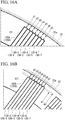
- Fig. 16A is a view for explaining a problem of an air gap between an outer circumferential edge of each yoke and the inner circumferential surface of the permanent magnet and is a view for explaining a variation occurring in the air gap due to the obliquely disposed yoke.
- Fig. 16B is a view for explaining a problem of an air gap between the outer circumferential edge of each yoke and the inner circumferential surface of the permanent magnet, and is a view illustrating a state in which a position of an outer circumferential edge of each plate-shaped member constituting the yoke is adjusted so that the air gap is made uniform.
- a notch part 135 is provided on at least one of one end side and the other end side in the circumferential direction of the inner circumferential side magnetic pole part 123 to avoid interference with an inner circumferential end of an adjacent yoke 120A.
- an inclination direction of the first yoke actual disposition plane SA1 with respect to the disposition reference plane SA0 of the first yoke 120A and an inclination direction of the second yoke actual disposition plane SB1 with respect to the disposition reference plane SB0 of the second yoke 120B are defined as an inclination direction of each yoke.
- the seven laminated plate-shaped members 130 are illustrated as reference signs 130-1 to 130-7 which are individually distinguished from a front side to a rear side in the inclination direction.
- dimensions of the laminated plate-shaped members 130 are determined such that a position of an inner circumferential end in the radial direction of a laminated plate-shaped member (for example, the plate-shaped member 130-1) positioned on a front side in the inclination direction of the yoke 120A (120B) is on a radial outer side of a position of an inner circumferential end in the radial direction of a laminated plate-shaped member (for example, the plate-shaped member 130-7) positioned on a rear side in the inclination direction of the yoke 120A (120B).
- a radial dimension K1 of the plate-shaped member 130-1 positioned at a front end in the inclination direction of the first yoke 120A (120B) may be smaller than a radial dimension K2 of the plate-shaped member 130-2 positioned on a front side following the plate-shaped member 130-1 by a dimension K 3.
- a radial dimension K2 of the plate-shaped member 130-2 may be smaller than a radial dimension K4 of the plate-shaped members 130-3 to 130-7 positioned on the rear side in the inclination direction of the plate-shaped member 130-2 by a dimension K5.
- the notch part 135 is secured at the front end in the inclination direction of the inner circumferential end of the inner circumferential side magnetic pole part 123 of the yoke 120A (120B) so that interference with an inner circumferential end of an inner circumferential side magnetic pole part 123 of a yoke 120A (120B) adjacent thereto is avoided.
- a radial dimension of the plate-shaped members 130-2 to 130-7 may be the same, and only the radial dimension K1 of the plate-shaped member 130-1 positioned at the foremost end in the inclination direction may be smaller than the radial dimension of the other plate-shaped members 130-2 to 130-7.
- the radial dimension after the third plate-shaped member 130-3 from the plate-shaped member 130-1 at the foremost end in the inclination direction may also be such that the radial dimension of the plate-shaped member positioned on the rear side in the inclination direction increases from the plate-shaped members 130-3 toward 130-7.
- the notch part 135 is provided at the inner circumferential end on the front side in the inclination direction of the yoke 120A (120B)
- interference can be avoided even when the interval between the plurality of yokes 120A (120B) aligned in the circumferential direction is made close to each other.
- a large number of yokes 120A (120B) can be disposed by reducing the disposition interval of the yokes 120A (120B).
- a position of an outer circumferential end in the radial direction of the laminated plate-shaped member (for example, the plate-shaped member 130-7) positioned on the rear side in the inclination direction of the yokes 120A and 120B is formed to be recessed toward a radial inner side with respect to a position of an outer circumferential end in the radial direction of the laminated plate-shaped member (for example, the plate-shaped member 130-1) positioned on the front side in the inclination direction.
- a gap (air gap) d7 between the outer circumferential end in the radial direction of the laminated plate-shaped member (for example, the plate-shaped member 130-7 at the rear end) and the inner circumferential surface 22a of the permanent magnet 22 at a position on the rear side in the inclination direction is larger than a gap (air gap) d1 between the outer circumferential end in the radial direction of the laminated plate-shaped member (for example, the plate-shaped member 130-1 at the front end) and the inner circumferential surface 22a of the permanent magnet 22 at a position on the front side in the inclination direction.
- a deviation occurs in the air gaps d1 to d7.
- the gaps (air gaps) d1 to d7 between the outer circumferential ends of the respective plate-shaped members 130-1 to 130-7 and the inner circumferential surface 22a of the permanent magnet 22 satisfy d1 ⁇ d2 ⁇ d3 ⁇ d4 ⁇ d5 ⁇ d6 ⁇ d7.
- the position of the outer circumferential end in the radial direction of the laminated plate-shaped member (for example, the plate-shaped member 130-7) positioned on the rear side in the inclination direction of each of the yokes 120A and 120B protrudes outward in the radial direction with respect to the position of the outer circumferential end in the radial direction of the laminated plate-shaped member (for example, the plate-shaped member 130-1) positioned on the front side in the inclination direction of each of the yokes 120A and 120B.
- protruding dimensions of the outer circumferential edges of the outer circumferential side magnetic pole part 121 toward the outer diameter side in each of the yokes 120A and 120B are changed in stages according to the lamination order from a minimum value m1 of the laminated plate-shaped member 130-1 positioned at the front end in the inclination direction of each of the yokes 120A and 120B to a maximum value m2 of the laminated plate-shaped member 130-7 positioned at the rear end in the inclination direction of each of the yokes 120A and 120B.
- the gaps (air gaps) d1 to d7 between the outer circumferential edges of each of the yokes 120A and 120B and the inner circumference of the permanent magnet 22 can be made uniform.
- the following method can also be employed as a method of making the position of the outer circumferential end in the radial direction of the laminated plate-shaped member positioned on the rear side in the inclination direction of each of the yokes 120A and 120B protrude outward in the radial direction with respect to the position of the outer circumferential end in the radial direction of the laminated plate-shaped member 130 positioned on the front side in the inclination direction of each of the yokes 120A and 120B. That is, a method in which dimensions of the plate-shaped members 130 laminated on the front side and the rear side in the inclination direction are made different can be employed. A method in which lamination positions of the plate-shaped members 130 laminated on the front side and the rear side in the inclination direction are deviated can be employed.
- Power generation of the hub dynamo 10 configured as above is performed as follows.
- an alternating magnetic flux is generated in the inner circumferential side magnetic pole parts 123 of both the yokes 120A and 120B magnetically connected to each other. Due to the alternating magnetic flux generated on the inner circumference side of the coil, a current is caused to flow through the coil 140 of the stator 101 and thereby power generation is performed.
- each of the yokes 120A and 120B of the present hub dynamo 10 is configured as a laminated body of a plurality of plate-shaped members 130, generation of the eddy current can be inhibited.
- the first yoke 120A and the second yoke 120B are not disposed on the plane in the radial direction (yoke disposition reference planes SA0 and SB0) but disposed on the plane inclined with respect to the radial direction (yoke actual disposition planes SA1 and SAB1). Therefore, the inner circumferential side magnetic pole part 123 of the first yoke 120A and the inner circumferential side magnetic pole part 123 of the second yoke 120B can be brought into contact with each other in a one-to-one relationship.
- a gap G formed on a contact surface between the first yoke 120A and the second yoke 120B due to a variation caused by a dimensional tolerance or the like of the yokes 120A and 120B as illustrated in Fig. 17B can be eliminated, and a degree of close contact of the contact surface can be increased.
- magnetic connection of the yokes 120A and 120B can be stabilized, iron loss can be reduced, and efficiency can be improved.
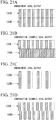
- the first yoke 120A and the second yoke 120B can be connected one-to-one. Therefore, the number of required yokes 120A and 120B can be reduced. For example, when an output is reduced to 75% from the state of 100% output illustrated in Fig. 18 , the number of yokes 120A and 120B need only be simply reduced to 3/4 as illustrated in Fig. 19 . When the output is reduced to 50%, as illustrated in FIG. 20 , the number of yokes 120A and 120B to be used need only be simply reduced to 1/2.
- connection between the first yoke 120A and the second yoke 120B can be made in a one-to-one relationship. Therefore, when an output is adjusted downward from a 100% state to, for example, 50% or 25%, the number of first yokes 120A and second yokes 120B need only be reduced by an equivalent number as illustrated in Figs. 21A and 21C , and the number of required yokes 120A and 120B can be reduced.
- axial end portions of the yokes 120A and 120B are respectively engaged with the guide grooves 113A and 113B and the engaging grooves 114A and 114B of the flanges 112A and 112B of the coil bobbin 110. Therefore, the yoke can be positioned on a plane inclined with respect to the radial direction (yoke actual disposition planes SA1 and SB1). Accordingly, by assembling the yokes 120A and 120B to the coil bobbin 110, a positional relationship between the coil 140 wound around the coil bobbin 110 and the yokes 120A and 120B can be appropriately determined.
- the gap (air gap) between the outer circumferential edge of the yokes 120A and 120B (outer circumferential edge of the outer circumferential side magnetic pole part 121 of each yoke) and the inner circumferential surface 22a of the permanent magnet 22 can be made uniform. As a result, power generation efficiency can be improved.
- the notch part 135 is provided on at least one of one end side and the other end side in the circumferential direction of the inner circumferential end of each of the yokes 120A and 120B so that interference with an inner circumferential end of a yoke adjacent thereto is avoided. Therefore, interference of the inner circumferential part of each of the yokes 120A and 120B with an inner circumferential part of each of the yokes 120A and 120B adjacent thereto can be avoided, and thus the yokes 120A and 120B can be disposed close to each other in the circumferential direction. Therefore, the number of disposed yokes can be increased.
- the present invention is not limited to the above-described embodiment, and includes various modifications added to the above-described embodiment within the scope not deviating from the gist of the present invention.
- the number of laminated sheets of the plate-shaped member 130 in constituting the yokes 120A and 120B may be arbitrarily determined.
- the number of yokes 120A and 120B at the time of 100% output is not limited to 32 yokes.
- the number of stators 101 is not limited to one, and two or three stators 101 may be disposed on the hub axle 11.
- stator unit 100 is constituted by one stator 101 .
- the present invention is not limited thereto, and the stator unit 100 may be constituted by two or more stators 101 disposed to be aligned on the hub axle 11. In this case, it is possible to generate a phase-shifted alternating current by shifting phases of the two stators 101.
Landscapes
- Engineering & Computer Science (AREA)
- Power Engineering (AREA)
- Mechanical Engineering (AREA)
- Iron Core Of Rotating Electric Machines (AREA)
- Permanent Magnet Type Synchronous Machine (AREA)
Applications Claiming Priority (2)
| Application Number | Priority Date | Filing Date | Title |
|---|---|---|---|
| JP2016248242A JP6776114B2 (ja) | 2016-12-21 | 2016-12-21 | ハブダイナモ |
| PCT/JP2017/042590 WO2018116758A1 (ja) | 2016-12-21 | 2017-11-28 | ハブダイナモ |
Publications (2)
| Publication Number | Publication Date |
|---|---|
| EP3561998A1 true EP3561998A1 (de) | 2019-10-30 |
| EP3561998A4 EP3561998A4 (de) | 2020-07-29 |
Family
ID=62627707
Family Applications (1)
| Application Number | Title | Priority Date | Filing Date |
|---|---|---|---|
| EP17883171.5A Withdrawn EP3561998A4 (de) | 2016-12-21 | 2017-11-28 | Nabendynamo |
Country Status (4)
| Country | Link |
|---|---|
| EP (1) | EP3561998A4 (de) |
| JP (1) | JP6776114B2 (de) |
| CN (1) | CN110114959B (de) |
| WO (1) | WO2018116758A1 (de) |
Family Cites Families (12)
| Publication number | Priority date | Publication date | Assignee | Title |
|---|---|---|---|---|
| US6133669A (en) * | 1997-12-31 | 2000-10-17 | Tupper; Christopher N. | Low-loss magnet core for high frequency claw-pole-type alternator |
| JP3644636B2 (ja) * | 2002-05-09 | 2005-05-11 | 株式会社シマノ | クローポール形発電機及び自転車用ハブダイナモ |
| JP3740555B2 (ja) * | 2003-01-22 | 2006-02-01 | 株式会社一宮電機 | クローポール型発電機 |
| JP2004260921A (ja) * | 2003-02-26 | 2004-09-16 | Ichinomiya Denki:Kk | 自転車用ハブダイナモ |
| JP3752492B2 (ja) * | 2003-03-28 | 2006-03-08 | 株式会社シマノ | 自転車用ハブ |
| JP2005041428A (ja) * | 2003-07-25 | 2005-02-17 | Mitsuba Corp | ハブダイナモ |
| CN2696969Y (zh) * | 2004-04-02 | 2005-05-04 | 蔡明达 | 自行车发电花毂 |
| JP4164071B2 (ja) * | 2005-02-04 | 2008-10-08 | シマノ シンガポール ピーティーイー.リミテッド. | クローポール形発電機及び自転車用発電ハブ |
| JP2008141893A (ja) * | 2006-12-04 | 2008-06-19 | Shimano Inc | 人力駆動車用発電機構のコイル組立体及び人力駆動車用発電ハブ |
| JP5382686B2 (ja) * | 2008-11-12 | 2014-01-08 | 株式会社シマノ | クローポール形発電機及び自転車用発電ハブ |
| JP5357937B2 (ja) * | 2011-08-26 | 2013-12-04 | 株式会社シマノ | 自転車用発電ハブの固定子および自転車用発電ハブ |
| CN203166720U (zh) * | 2011-12-23 | 2013-08-28 | 宁波韵升股份有限公司 | 一种车辆用交流发电机 |
-
2016
- 2016-12-21 JP JP2016248242A patent/JP6776114B2/ja active Active
-
2017
- 2017-11-28 WO PCT/JP2017/042590 patent/WO2018116758A1/ja not_active Ceased
- 2017-11-28 CN CN201780078625.1A patent/CN110114959B/zh active Active
- 2017-11-28 EP EP17883171.5A patent/EP3561998A4/de not_active Withdrawn
Also Published As
| Publication number | Publication date |
|---|---|
| WO2018116758A1 (ja) | 2018-06-28 |
| CN110114959A (zh) | 2019-08-09 |
| EP3561998A4 (de) | 2020-07-29 |
| CN110114959B (zh) | 2021-08-06 |
| JP2018102094A (ja) | 2018-06-28 |
| JP6776114B2 (ja) | 2020-10-28 |
Similar Documents
| Publication | Publication Date | Title |
|---|---|---|
| US9577502B2 (en) | Transverse flux permanent magnet rotatory device | |
| US8304949B2 (en) | Axial gap motor | |
| US8701805B2 (en) | Motor having rotors arranged concentrically and driving apparatus having the motor | |
| JP5382686B2 (ja) | クローポール形発電機及び自転車用発電ハブ | |
| US20140175930A1 (en) | Permanent magnet embedded type rotating electrical machine | |
| JP2012157143A (ja) | モータ | |
| EP3062419A1 (de) | Rotor für elektrische drehmaschinen | |
| TW200401495A (en) | Claw-pole generator and hub dynamo for bicycle | |
| US20140132121A1 (en) | Transverse flux motor | |
| US20130009506A1 (en) | Rotating electric machine | |
| JP6251919B2 (ja) | ハブダイナモ | |
| CN105492308A (zh) | 轮毂发电机 | |
| CN111033985B (zh) | 轮毂发电机 | |
| US10840762B2 (en) | Brushless motor and electric bicycle provided with the same | |
| US9787153B2 (en) | Outer rotor type dynamo | |
| US20140175915A1 (en) | Motor of outer rotor type | |
| EP3561998A1 (de) | Nabendynamo | |
| JP5998323B2 (ja) | 自転車用発電機 | |
| JP2015033254A (ja) | ステータコア | |
| TWI712248B (zh) | 自行車用發電機 | |
| JP2006271142A (ja) | 回転機 | |
| TWI685181B (zh) | 自行車用發電機 | |
| JP5580064B2 (ja) | ハブダイナモ | |
| JP5649612B2 (ja) | ハブダイナモ | |
| JP2009278768A (ja) | アウターロータ型ブラシレスモータ |
Legal Events
| Date | Code | Title | Description |
|---|---|---|---|
| STAA | Information on the status of an ep patent application or granted ep patent |
Free format text: STATUS: THE INTERNATIONAL PUBLICATION HAS BEEN MADE |
|
| PUAI | Public reference made under article 153(3) epc to a published international application that has entered the european phase |
Free format text: ORIGINAL CODE: 0009012 |
|
| STAA | Information on the status of an ep patent application or granted ep patent |
Free format text: STATUS: REQUEST FOR EXAMINATION WAS MADE |
|
| 17P | Request for examination filed |
Effective date: 20190613 |
|
| AK | Designated contracting states |
Kind code of ref document: A1 Designated state(s): AL AT BE BG CH CY CZ DE DK EE ES FI FR GB GR HR HU IE IS IT LI LT LU LV MC MK MT NL NO PL PT RO RS SE SI SK SM TR |
|
| AX | Request for extension of the european patent |
Extension state: BA ME |
|
| DAV | Request for validation of the european patent (deleted) | ||
| DAX | Request for extension of the european patent (deleted) | ||
| A4 | Supplementary search report drawn up and despatched |
Effective date: 20200626 |
|
| RIC1 | Information provided on ipc code assigned before grant |
Ipc: H02K 7/18 20060101ALI20200622BHEP Ipc: H02K 1/14 20060101AFI20200622BHEP Ipc: B62J 6/12 20060101ALI20200622BHEP Ipc: H02K 21/22 20060101ALI20200622BHEP Ipc: H02K 3/52 20060101ALI20200622BHEP |
|
| GRAP | Despatch of communication of intention to grant a patent |
Free format text: ORIGINAL CODE: EPIDOSNIGR1 |
|
| STAA | Information on the status of an ep patent application or granted ep patent |
Free format text: STATUS: GRANT OF PATENT IS INTENDED |
|
| INTG | Intention to grant announced |
Effective date: 20210915 |
|
| STAA | Information on the status of an ep patent application or granted ep patent |
Free format text: STATUS: THE APPLICATION IS DEEMED TO BE WITHDRAWN |
|
| 18D | Application deemed to be withdrawn |
Effective date: 20220126 |