EP3560876B1 - Aufzugskabine und aufzugssystem - Google Patents
Aufzugskabine und aufzugssystem Download PDFInfo
- Publication number
- EP3560876B1 EP3560876B1 EP18169863.0A EP18169863A EP3560876B1 EP 3560876 B1 EP3560876 B1 EP 3560876B1 EP 18169863 A EP18169863 A EP 18169863A EP 3560876 B1 EP3560876 B1 EP 3560876B1
- Authority
- EP
- European Patent Office
- Prior art keywords
- cover plate
- frame
- elevator car
- elevator
- fixing
- Prior art date
- Legal status (The legal status is an assumption and is not a legal conclusion. Google has not performed a legal analysis and makes no representation as to the accuracy of the status listed.)
- Active
Links
Images


Classifications
-
- B—PERFORMING OPERATIONS; TRANSPORTING
- B66—HOISTING; LIFTING; HAULING
- B66B—ELEVATORS; ESCALATORS OR MOVING WALKWAYS
- B66B11/00—Main component parts of lifts in, or associated with, buildings or other structures
- B66B11/02—Cages, i.e. cars
- B66B11/0206—Car frames
-
- B—PERFORMING OPERATIONS; TRANSPORTING
- B66—HOISTING; LIFTING; HAULING
- B66B—ELEVATORS; ESCALATORS OR MOVING WALKWAYS
- B66B11/00—Main component parts of lifts in, or associated with, buildings or other structures
- B66B11/02—Cages, i.e. cars
- B66B11/0226—Constructional features, e.g. walls assembly, decorative panels, comfort equipment, thermal or sound insulation
- B66B11/0246—Maintenance features
-
- B—PERFORMING OPERATIONS; TRANSPORTING
- B66—HOISTING; LIFTING; HAULING
- B66B—ELEVATORS; ESCALATORS OR MOVING WALKWAYS
- B66B11/00—Main component parts of lifts in, or associated with, buildings or other structures
- B66B11/02—Cages, i.e. cars
- B66B11/0226—Constructional features, e.g. walls assembly, decorative panels, comfort equipment, thermal or sound insulation
-
- B—PERFORMING OPERATIONS; TRANSPORTING
- B66—HOISTING; LIFTING; HAULING
- B66B—ELEVATORS; ESCALATORS OR MOVING WALKWAYS
- B66B11/00—Main component parts of lifts in, or associated with, buildings or other structures
- B66B11/02—Cages, i.e. cars
- B66B11/0226—Constructional features, e.g. walls assembly, decorative panels, comfort equipment, thermal or sound insulation
- B66B11/0233—Lighting systems
-
- B—PERFORMING OPERATIONS; TRANSPORTING
- B66—HOISTING; LIFTING; HAULING
- B66B—ELEVATORS; ESCALATORS OR MOVING WALKWAYS
- B66B19/00—Mining-hoist operation
-
- B—PERFORMING OPERATIONS; TRANSPORTING
- B66—HOISTING; LIFTING; HAULING
- B66B—ELEVATORS; ESCALATORS OR MOVING WALKWAYS
- B66B9/00—Kinds or types of lifts in, or associated with, buildings or other structures
-
- F—MECHANICAL ENGINEERING; LIGHTING; HEATING; WEAPONS; BLASTING
- F16—ENGINEERING ELEMENTS AND UNITS; GENERAL MEASURES FOR PRODUCING AND MAINTAINING EFFECTIVE FUNCTIONING OF MACHINES OR INSTALLATIONS; THERMAL INSULATION IN GENERAL
- F16B—DEVICES FOR FASTENING OR SECURING CONSTRUCTIONAL ELEMENTS OR MACHINE PARTS TOGETHER, e.g. NAILS, BOLTS, CIRCLIPS, CLAMPS, CLIPS OR WEDGES; JOINTS OR JOINTING
- F16B2200/00—Constructional details of connections not covered for in other groups of this subclass
- F16B2200/83—Use of a magnetic material
Definitions
- the invention relates to an elevator car with a removable cover and to an elevator system comprising such an elevator car.
- the invention further relates to methods of mounting and removing a cover plate to/from an elevator car.
- An elevator system comprises at least one elevator car traveling along a hoistway between a plurality of landings.
- the elevator car has a ceiling.
- the ceiling may include a removable cover for closing an opening formed within the ceiling.
- a side frame of an elevator car is composed of a pair of vertical frame members positioned on both left and right ends of a side surface, and a horizontal frame member positioned on these upper ends.
- a control board main body to control operation of a car and opening-closing of a door is arranged in a second casing part adjacently arranged on the lower side of a first casing part to house a telephone to emergently communicate with an external part.
- a control board for controlling operation of the elevator car and opening-closing of the door is housed between the vertical frame members of the side frame, and does not protrude outside from these vertical frame members.
- an elevator car comprising a ceiling with an opening and a removable cover which allows compensating tolerances of manufacturing so that the opening is reliably closed by the cover.
- an elevator car comprises a frame.
- the frame in particular may be arranged horizontally in an upper portion of the elevator car forming part of a ceiling of the elevator car.
- the elevator car further comprises a removable cover plate.
- the cover plate includes at least one aperture formed in a first end of the cover plate allowing at least one fixing element extending from the frame to pass through the at least one aperture for fixing the cover plate to the frame.
- At least one permanent magnet is provided at an opposing second end of the cover plate and/or at a portion of the frame abutting the second end of the cover plate.
- the at least one permanent magnet is configured for fixing the second end of the cover plate to an adjacent portion of the frame, in particular to a metallic portion of the frame, by means of its magnetic force.
- the second end of the cover plate is provided with a c-shaped profile configured for embracing a portion of the frame when the cover plate is mounted to the frame.
- Exemplary embodiments of the invention further include an elevator system comprising at least one elevator car according to an exemplary embodiment of the invention.
- Exemplary embodiments of the invention also include a method of removing the cover plate comprising a permanent magnet from such an elevator car, wherein the method includes detaching the c-shaped profile from the portion of the frame and disengaging the at least one fixing element, and removing the cover by disengaging the permanent magnet from the frame.
- the method includes disengaging the at least one fixing element and removing the cover plate by disengaging the permanent magnet from the cover plate.
- Exemplary embodiments of the invention further include a method of mounting a cover plate to an elevator car according to an exemplary embodiment of the invention, wherein the method comprises: positioning the cover plate on the frame so that at least one permanent magnet provided at the cover plate attaches to a portion of the frame, encompassing a portion of the frame with the c-shape profile, and fixing the first end of the cover plate to the frame with at least one fixing element extending through the at least one aperture formed within the cover plate.
- Exemplary embodiments of the invention further include a method of mounting a cover plate to an elevator car according to an exemplary embodiment of the invention, wherein the method comprises: positioning the cover plate on the frame so that at least one permanent magnet provided at the frame attaches to the cover plate, encompassing a portion of the frame with the c-shape profile, and fixing the first end of the cover plate to the frame with at least one fixing element extending through the at least one aperture formed within the cover plate.
- Exemplary embodiments of the invention allow fixing the cover plate securely to the frame with the position of the cover plate with respect to the frame being set by the fixing elements extending through the apertures formed within the cover plate.
- the position of the at least one permanent magnet with respect to the frame is variable, variations and tolerances of the dimensions, such as the length of the cover plate and/or of the frame, may be compensated with the cover plate still being securely attached to the frame.
- a plurality of apertures may be formed within the cover plate, and a plurality of fixing elements may extend from the frame. Providing a plurality of fixing elements in combination with a plurality of apertures allows defining the position of the cover plate with respect to the frame with high accuracy. It in particular allows preventing a rotation of the cover plate around the fixing element(s). It further allows distributing the forces acting onto the fixing elements among a plurality of fixing elements.
- the apertures and fixing elements may be arranged along a common line.
- the at least one fixing element may include a bolt or screw.
- a plurality of permanent magnets may be provided at an opposing second end of the cover plate and/or at the portion of the frame abutting the second end of the cover plate.
- the permanent magnets in particular may be arranged along a common line. Providing a plurality of magnets increases the magnetic force fixing the cover plate to the frame.
- the cover plate and/or the frame may be made at least partially of metal in order to allow the magnets to attach to the cover plate or to the frame by their magnetic forces.
- Other parts of the cover plate and/or of the frame may be made of plastic for reducing the weight of the cover plate or of the frame, respectively.
- the frame may be made at least partially of metal plates, in particular of bent metal plates. Bent metal plates provide a strong frame which is easy to produce at low costs.
- the frame and/or the cover plate may have a rectangular shape, in particular a quadratic shape, respectively.
- the frame in particular may include longitudinal bars extending in a longitudinal direction and crossbars extending between the longitudinal bars.
- the crossbars in particular may extend orthogonally to the extension of the longitudinal bars so that the longitudinal bars and the crossbars form a rectangular frame.
- the crossbars may include outer crossbars extending between the ends of the longitudinal bars and inner crossbars extending between the longitudinal bars at positions located in between the outer crossbars.
- the frame also may comprise a plurality of longitudinal bars and a plurality of crossbars forming a chessboard like structure comprising at plurality of openings.
- One or more of the openings may be covered by a removable cover plate according to an exemplary embodiment of the invention.
- the space(s) formed between the inner crossbars and the space(s) formed between an outer crossbar and an adjacent inner crossbar may be closed by at least one cover plate, respectively.
- At least one cover plate may be a removable cover plate according to an exemplary embodiment of the invention.
- At least one fixing element may be provided with a locking mechanism for preventing an unauthorized removal of the cover plate.
- the cover plate may be at least partially transparent in order to allow light to pass through the cover plate.
- At least one lighting device configured for lighting an interior space of the elevator car may be mounted to the cover plate.
- Figure 5 depicts a side view of the configuration shown in Figure 4 .
- Figure 1 schematically depicts an elevator system 2 comprising an elevator car 6 according to an exemplary embodiment of the invention.
- the elevator system 2 comprises a hoistway 4 extending in a longitudinal direction between a plurality of landings 8 located on different floors.
- the elevator car 6 comprises a floor 16, a ceiling 18 and sidewalls 17 extending between the floor 16 and the ceiling 18 defining an interior space 12 of the elevator car 6. Only one sidewall 17 is depicted in the schematic illustration of Fig. 1 .
- the elevator car 6 is movably suspended within the hoistway 4 by means of a tension member 3.
- the tension member 3 for example a rope or belt, is connected to a drive 5, which is configured for driving the tension member 3 in order to move the elevator car 6 along the longitudinal direction / height of the hoistway 4 between the plurality of landings 8.
- Each landing 8 is provided with a landing door (elevator hoistway door) 10, and the elevator car 6 is provided with a corresponding elevator car door 11 allowing passengers to transfer between a landing 8 and the interior space 12 of the elevator car 6 when the elevator car 6 is positioned at the respective landing 8.
- a landing door elevator hoistway door
- the elevator car 6 is provided with a corresponding elevator car door 11 allowing passengers to transfer between a landing 8 and the interior space 12 of the elevator car 6 when the elevator car 6 is positioned at the respective landing 8.
- the exemplary embodiment of the elevator system 2 shown in Fig. 1 employs a 1:1 roping for suspending the elevator car 6.
- the skilled person easily understands that the type of the roping is not essential for the invention and that different kinds of roping, e.g. a 2:1 roping, may be used as well.
- the elevator system 2 may further include a counterweight (not shown) moving concurrently and in opposite direction with respect to the elevator car 6.
- the elevator system 2 may be an elevator system 2 without a counterweight, as it is shown in Fig. 1 .
- the drive 5 may be any form of drive used in the art, e.g. a traction drive, a hydraulic drive or a linear drive.
- the elevator system 2 may have a machine room or may be a machine room-less elevator system.
- the elevator system 2 may use a tension member 3, as it is shown in Fig. 1 , or it may be an elevator system without a tension member 3, comprising e.g. a hydraulic drive or a linear drive (not shown).
- the drive 5 is controlled by an elevator control 15 for moving the elevator car 6 along the hoistway 4 between the different landings 8.
- Input to the elevator control 15 may be provided via landing control panels 7a, which are provided on each landing 8 close to the elevator landing doors 10, and/or via a car operation panel 7b provided inside the elevator car 6.
- the landing control panels 7a and the car operation panel 7b may be connected to the elevator control 15 by means of electrical lines, which are not shown in Fig. 1 , in particular by an electric bus, e.g. a field bus such as a CAN bus, or by means of wireless data connections.
- an electric bus e.g. a field bus such as a CAN bus
- wireless data connections e.g.
- the elevator car 6 is provided with a position sensor 19.
- the position sensor 19 may be arranged at the top of the elevator car 6 as shown in Fig. 1 .
- the position sensor 19 may be provided at a side of the elevator car 6 or at the bottom, e.g. below a floor 16, of the elevator car 6.
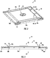
- FIG 2 shows a perspective view of a ceiling 18 of an elevator car 6 according to an exemplary embodiment of the invention.
- the ceiling includes a frame 20 and a cover plate 22 arranged in a closed position, i.e. in a position in which the cover plate 22 is contact with the frame 20.
- Figure 3 depicts a side view of said closed configuration.
- Figure 4 shows a perspective view of the ceiling 18 shown in Figures 2 and 3 , wherein the cover plate 22 is arranged in an open position, i.e. in a position in which the cover plate 22 is spaced apart from the frame 20.
- Figure 5 depicts a side view of said open configuration.
- the frame 20 comprises a plurality of bars 34a, 34b, 36a, 36b, 38a, 38b, in particular two longitudinal bars 34a, 34b and four crossbars 36a, 36b, 38a, 38b respectively extending between the longitudinal bars 34a, 34b.
- the crossbars 36a, 36b, 38a, 38b in particular extend orthogonally to the longitudinal bars 34a, 34b forming a rectangular frame 20.
- the crossbars 36a, 36b, 38a, 38b include outer crossbars 36a, 36b respectively extending between the ends of the longitudinal bars 34a, 34b; and inner crossbars 38a, 38b, respectively extending between the longitudinal bars 34a, 34b at positions located in between the outer crossbars 36a, 36b.
- the rectangular opening 40 in particular may have the shape of a square.
- the cover plate 22 is configured for closing the opening 40.
- the cover plate 22 approximately has the same dimensions as the opening 40.
- Two apertures 28 are formed at a first end 22a of the cover plate 22 arranged next to a first inner crossbar 38a.
- the first crossbars 36a, 38a and first end 22a of the cover plate 22 are shown on the right sides of Figures 2 to 5 , respectively.
- Fixing elements 30, such as bolts or screws, are provided at the first inner crossbar 38a.
- the positions of the fixing element 30 match with the positions of the apertures 28 formed within the cover plate 22.
- the fixing elements 30 extend through the apertures 28 for fixing the cover plate 22 to the frame 20.
- At least one permanent magnet 24 (see Figures 3 and 5 ) is provided at the opposing second end 22b of the cover plate 22 arranged next to a second inner crossbar 38b.
- the second crossbars 36b, 38b and the second end 22b of the cover plate 22 are shown on the left sides of Figures 2 to 5 .
- At least a portion of the second inner crossbar 38b is made of a magnetic material, e.g. a metal.
- a magnetic material e.g. a metal
- the cover plate 22 is securely fixed to the frame 20 by the fixing elements 30 extending through the apertures 28 at its first end 22a, and by the at least one permanent magnet 24 interacting with the second inner crossbar 38b at its opposing second end 22.
- the position of the cover plate 22 with respect to the frame 20 is set by the fixing elements 30 extending through the apertures 28 formed in the first end 22a of the cover plate 22.
- the position of the permanent magnet(s) 24 with respect to the second inner crossbar 38b is variable to a certain extent. This variability allows compensating for variations and tolerances of the dimensions, in particular the length of the cover plate 22 and/or the distance between the inner crossbars 38a, 38b, while still securely attaching the cover plate 22 to the frame 20.
- At least one permanent magnet may be mounted to the second inner crossbar 38b in order to interact with the second end 22b of the cover plate 22.
- the cover plate 22 is made at least partially of a magnetic material, in particular a metallic material.
- a magnetic material, in particular a metallic material, such as a metallic strip may be provided at least at the second end 22b of the cover plate 22.
- a c-shaped profile 26 is provided at the second end 22b of the cover plate 22.
- the c-shaped profile 26 may be formed integrally with the cover plate 22.
- the c-shaped profile 26 may be attached to the second end 22b of the cover plate 22.
- the c-shaped profile 26 embraces the second inner crossbar 38b. Such a configuration prevents the second end 22b of the cover plate 22 from being lifted from the second inner crossbar 38b without opening/removing the fixing elements 30 at the first inner crossbar 38a.
- opening/removing the fixing elements 30 may be possible from inside and/or from outside the elevator car 6.
- the fixing elements 30 may be provided with locking mechanisms (not shown), such as a mechanical lock or a special type of screws which may be removed only with a special key in order to prevent unauthorized persons from removing the cover plate 22.
- locking mechanisms such as a mechanical lock or a special type of screws which may be removed only with a special key in order to prevent unauthorized persons from removing the cover plate 22.
- the first side 22a of the cover plate 22 may be detached from the first inner crossbar 38a.
- the second side 22b of the cover plate 22 may be separated from the second inner crossbar 38b overcoming the magnetic forces of the permanent magnet(s) 24, and the c-shaped profile 26 may be detached from the second inner crossbar 38b.
- the cover plate 22 may be provided with at least one lighting device 42 configured for lighting the interior space 12 of the elevator car 6.
- the at least one lighting device 42 may be mounted to a bottom side of the cover plate 22 facing the interior space 12, as it is shown in Figure 5 .
- the cover plate 22 may be at least partially transparent.
- the at least one lighting device 42 may be attached to the upper side of the cover plate 22 outside the elevator car 6 facing a transparent portion of the cover plate 22.
- Electrical connectors may be provided at at least one side 22a, 22b of the cover plate 22 for delivering electric energy to the at least one lighting device 42.
- a graphic sign 32 instructing people, such as maintenance personnel, not to step onto the cover plate 22 is provided on the upper side of the cover plate 22.
Landscapes
- Engineering & Computer Science (AREA)
- Structural Engineering (AREA)
- Civil Engineering (AREA)
- Mechanical Engineering (AREA)
- Automation & Control Theory (AREA)
- Cage And Drive Apparatuses For Elevators (AREA)
Claims (12)
- Aufzugskabine (6), einen Rahmen (20) und eine entfernbare Abdeckplatte (22) umfassend, wobei die Abdeckplatte (22) Folgendes umfasst:mindestens eine Öffnung (28), die in einem ersten Ende (22a) der Abdeckplatte (22) ausgebildet ist und die es mindestens einem Befestigungselement (30), das sich von dem Rahmen (20) aus erstreckt, ermöglicht, durch die mindestens eine Öffnung (28) durchzutreten, um die Abdeckplatte (22) an dem Rahmen (20) zu befestigen; undmindestens einen Permanentmagneten (24), der an einem entgegengesetzten zweiten Ende (22b) der Abdeckplatte (22) und/oder an einem Abschnitt des Rahmens (20), der an das zweite Ende (22b) der Abdeckplatte (22) angrenzt, bereitgestellt ist;wobei der mindestens eine Permanentmagnet (24) so konfiguriert ist, dass er das zweite Ende (22b) der Abdeckplatte (22) an einem Abschnitt des Rahmens (20) befestigt; unddadurch gekennzeichnet, dass das zweite Ende (22b) der Abdeckplatte (22) mit einem C-förmigen Profil (26) versehen ist, das zum Umgreifen eines Abschnitts des Rahmens (20) konfiguriert ist, wenn die Abdeckplatte (22) an dem Rahmen (20) angebracht ist.
- Aufzugskabine (6) nach Anspruch 1, wobei eine Vielzahl von Öffnungen (28) innerhalb der Abdeckplatte (22) ausgebildet sind, wobei die Öffnungen (28) insbesondere entlang einer gemeinsamen Linie angeordnet sind.
- Aufzugskabine (6) nach Anspruch 1 oder 2, wobei eine Vielzahl von Permanentmagneten (24) an dem zweiten Ende (22b) der Abdeckplatte (22) und/oder an dem Abschnitt des Rahmens (20), der an das zweite Ende (22b) der Abdeckplatte (22) angrenzt, bereitgestellt sind, wobei die Permanentmagneten (24) insbesondere entlang einer gemeinsamen Linie angeordnet sind.
- Aufzugskabine (6) nach einem der vorstehenden Ansprüche, wobei die Abdeckplatte (22) und/oder der Rahmen (20) mindestens teilweise aus Metall und/oder Kunststoff hergestellt sind.
- Aufzugskabine (6) nach einem der vorstehenden Ansprüche, wobei der Rahmen (20) mindestens teilweise aus Metallplatten hergestellt ist, insbesondere aus gebogenen Metallplatten.
- Aufzugskabine (6) nach einem der vorstehenden Ansprüche, wobei der Rahmen (20) und/oder die Abdeckplatte (22) jeweils eine rechtwinklige Form aufweisen, insbesondere eine quadratische Form.
- Aufzugskabine (6) nach einem der vorstehenden Ansprüche, wobei die Abdeckplatte (22) mindestens teilweise transparent ist und/oder mindestens eine Beleuchtungsvorrichtung (42) zum Beleuchten eines Innenraums (12) der Aufzugskabine (6) umfasst.
- Aufzugskabine (6) nach einem der vorstehenden Ansprüche, wobei die Abdeckplatte (22) an dem Rahmen (20) durch mindestens ein Befestigungselement (30) befestigt ist.
- Aufzugskabine (6) nach Anspruch 8, wobei das mindestens eine Befestigungselement (30) einen Bolzen oder eine Schraube beinhaltet.
- Aufzugsystem (2), mindestens eine Aufzugskabine (6) nach einem der vorstehenden Ansprüche umfassend.
- Verfahren zum Entfernen der Abdeckplatte (22) von einer Aufzugskabine (6) nach Anspruch 8 oder 9, wobei das Verfahren Folgendes beinhaltet:Lösen des mindestens einen Befestigungselements (30); undEntfernen der Abdeckplatte (22) durch Abnehmen des C-förmigen Profils (26) von dem Abschnitt des Rahmens (20) und Lösen des Permanentmagneten (24) von dem Rahmen (20) oder von der Abdeckplatte (22).
- Verfahren zum Montieren einer Abdeckplatte (22) an einer Aufzugskabine (6) nach einem der Ansprüche 1 bis 9, wobei das Verfahren Folgendes umfasst:Positionieren der Abdeckplatte (22) an dem Rahmen (20), so dass die Abdeckplatte (22) an dem Rahmen (20) durch mindestens einen Permanentmagneten (24) angebracht ist;Umgreifen eines Abschnitts des Rahmens (20) mit dem C-förmigen Profil (26) vor dem Befestigen des ersten Endes (22a) der Abdeckplatte (22) an dem Rahmen (20) mit mindestens einem Befestigungselement (30), das sich durch die mindestens eine Öffnung (28) erstreckt, die innerhalb der Abdeckplatte (22) ausgebildet ist.
Priority Applications (4)
| Application Number | Priority Date | Filing Date | Title |
|---|---|---|---|
| ES18169863T ES2887006T3 (es) | 2018-04-27 | 2018-04-27 | Cabina de ascensor y sistema de ascensor |
| EP18169863.0A EP3560876B1 (de) | 2018-04-27 | 2018-04-27 | Aufzugskabine und aufzugssystem |
| US16/394,899 US20190330025A1 (en) | 2018-04-27 | 2019-04-25 | Elevator car and elevator system |
| CN201910342908.3A CN110407066B (zh) | 2018-04-27 | 2019-04-26 | 电梯轿厢及电梯系统 |
Applications Claiming Priority (1)
| Application Number | Priority Date | Filing Date | Title |
|---|---|---|---|
| EP18169863.0A EP3560876B1 (de) | 2018-04-27 | 2018-04-27 | Aufzugskabine und aufzugssystem |
Publications (2)
| Publication Number | Publication Date |
|---|---|
| EP3560876A1 EP3560876A1 (de) | 2019-10-30 |
| EP3560876B1 true EP3560876B1 (de) | 2021-06-02 |
Family
ID=62089643
Family Applications (1)
| Application Number | Title | Priority Date | Filing Date |
|---|---|---|---|
| EP18169863.0A Active EP3560876B1 (de) | 2018-04-27 | 2018-04-27 | Aufzugskabine und aufzugssystem |
Country Status (4)
| Country | Link |
|---|---|
| US (1) | US20190330025A1 (de) |
| EP (1) | EP3560876B1 (de) |
| CN (1) | CN110407066B (de) |
| ES (1) | ES2887006T3 (de) |
Families Citing this family (1)
| Publication number | Priority date | Publication date | Assignee | Title |
|---|---|---|---|---|
| USD1039236S1 (en) * | 2021-04-16 | 2024-08-13 | Nationwide Lifts, Inc. | Unitary elevator car floor |
Family Cites Families (9)
| Publication number | Priority date | Publication date | Assignee | Title |
|---|---|---|---|---|
| US4699251A (en) * | 1986-05-15 | 1987-10-13 | Westinghouse Electric Corp. | Elevator cab |
| JPH10139294A (ja) * | 1996-11-14 | 1998-05-26 | Otis Elevator Co | サイドフォーク型ホームエレベーターのかご |
| JP4481430B2 (ja) * | 2000-05-10 | 2010-06-16 | 三菱電機株式会社 | エレベーターかごの天井装置 |
| KR101116439B1 (ko) * | 2007-01-22 | 2012-03-08 | 미쓰비시덴키 가부시키가이샤 | 엘리베이터의 엘리베이터 칸 천장 장치 |
| JP5452012B2 (ja) * | 2008-11-26 | 2014-03-26 | 三菱電機株式会社 | 袖壁保持装置及びエレベータかご操作盤 |
| FI20116096L (fi) * | 2011-11-07 | 2013-05-08 | Kone Corp | Nivelöintijärjestely, kattoelementti ja hissi |
| JP6210937B2 (ja) * | 2014-06-11 | 2017-10-11 | 株式会社日立製作所 | エレベーター装置 |
| CN206232280U (zh) * | 2015-12-25 | 2017-06-09 | 东芝电梯株式会社 | 轿厢 |
| JP6194065B1 (ja) * | 2016-06-08 | 2017-09-06 | 東芝エレベータ株式会社 | エレベータかご室におけるミラーサイネージの取付構造及び取付方法 |
-
2018
- 2018-04-27 EP EP18169863.0A patent/EP3560876B1/de active Active
- 2018-04-27 ES ES18169863T patent/ES2887006T3/es active Active
-
2019
- 2019-04-25 US US16/394,899 patent/US20190330025A1/en not_active Abandoned
- 2019-04-26 CN CN201910342908.3A patent/CN110407066B/zh active Active
Also Published As
| Publication number | Publication date |
|---|---|
| CN110407066B (zh) | 2021-07-16 |
| ES2887006T3 (es) | 2021-12-21 |
| EP3560876A1 (de) | 2019-10-30 |
| US20190330025A1 (en) | 2019-10-31 |
| CN110407066A (zh) | 2019-11-05 |
Similar Documents
| Publication | Publication Date | Title |
|---|---|---|
| US9573791B2 (en) | Elevators and elevator arrangements with maintenance cabinet in landing wall | |
| AU2011287656B2 (en) | Magnetic lock for an operating unit in an elevator system | |
| US8746412B2 (en) | Elevator door frame with electronics housing | |
| ES2441443T3 (es) | Soporte de máquina de ascensor | |
| EP3309101A1 (de) | Aufzugskabine, aufzugssystem und verfahren zur überprüfung, wartung und/oder reparatur eines aufzugssystems | |
| EP3484807B1 (de) | Aufzugsanordnung für sichere wartungsarbeiten | |
| US20170362064A1 (en) | Elevator Car and Elevator System | |
| WO2013012249A2 (ko) | 엘리베이터 출입구 폭 이내 구간에 설치되는 카도어 자동개폐장치 | |
| JPWO2018079032A1 (ja) | エレベータの乗場戸開検出装置およびエレベータ | |
| CN101134548A (zh) | 具有轿厢和对重的电梯设备和用于布置电梯设备的方法 | |
| EP3560876B1 (de) | Aufzugskabine und aufzugssystem | |
| KR20220162692A (ko) | 레일 시스템 | |
| ES2441444T3 (es) | Sistema de ascensor que incluye sistemas electrónicos de control soportados sobre un soporte de máquina de ascensor | |
| CA2504897C (en) | Elevator monitoring unit and procedure for the maintenance of an elevator monitoring unit | |
| US4685537A (en) | Elevator system which utilizes both rigid and resilient mounting arrangments for door operator | |
| EP3299329B1 (de) | Aufzugskabine | |
| KR200462913Y1 (ko) | 엘리베이터의 인터록 장치 | |
| KR100904919B1 (ko) | 엘리베이터도어의 상부이탈방지장치 | |
| JP3305962B2 (ja) | エレベータかご装置 | |
| EP4477607A1 (de) | Bremskreislaufzugang von der landung | |
| WO2010016739A2 (ko) | 엘리베이터의 승장도어 이탈방지장치 | |
| HK1164254B (en) | Elevator door frame with electronics housing | |
| KR20060084156A (ko) | 엘리베이터 시스템의 승장도어 조립체 | |
| JP2771338B2 (ja) | エレベーターユニット付建物 | |
| CN120112472A (zh) | 用于电梯的轿厢及电梯 |
Legal Events
| Date | Code | Title | Description |
|---|---|---|---|
| PUAI | Public reference made under article 153(3) epc to a published international application that has entered the european phase |
Free format text: ORIGINAL CODE: 0009012 |
|
| STAA | Information on the status of an ep patent application or granted ep patent |
Free format text: STATUS: THE APPLICATION HAS BEEN PUBLISHED |
|
| AK | Designated contracting states |
Kind code of ref document: A1 Designated state(s): AL AT BE BG CH CY CZ DE DK EE ES FI FR GB GR HR HU IE IS IT LI LT LU LV MC MK MT NL NO PL PT RO RS SE SI SK SM TR |
|
| AX | Request for extension of the european patent |
Extension state: BA ME |
|
| STAA | Information on the status of an ep patent application or granted ep patent |
Free format text: STATUS: REQUEST FOR EXAMINATION WAS MADE |
|
| 17P | Request for examination filed |
Effective date: 20200206 |
|
| RBV | Designated contracting states (corrected) |
Designated state(s): AL AT BE BG CH CY CZ DE DK EE ES FI FR GB GR HR HU IE IS IT LI LT LU LV MC MK MT NL NO PL PT RO RS SE SI SK SM TR |
|
| GRAP | Despatch of communication of intention to grant a patent |
Free format text: ORIGINAL CODE: EPIDOSNIGR1 |
|
| STAA | Information on the status of an ep patent application or granted ep patent |
Free format text: STATUS: GRANT OF PATENT IS INTENDED |
|
| INTG | Intention to grant announced |
Effective date: 20210204 |
|
| GRAS | Grant fee paid |
Free format text: ORIGINAL CODE: EPIDOSNIGR3 |
|
| GRAA | (expected) grant |
Free format text: ORIGINAL CODE: 0009210 |
|
| STAA | Information on the status of an ep patent application or granted ep patent |
Free format text: STATUS: THE PATENT HAS BEEN GRANTED |
|
| REG | Reference to a national code |
Ref country code: CH Ref legal event code: EP |
|
| AK | Designated contracting states |
Kind code of ref document: B1 Designated state(s): AL AT BE BG CH CY CZ DE DK EE ES FI FR GB GR HR HU IE IS IT LI LT LU LV MC MK MT NL NO PL PT RO RS SE SI SK SM TR |
|
| REG | Reference to a national code |
Ref country code: GB Ref legal event code: FG4D |
|
| REG | Reference to a national code |
Ref country code: AT Ref legal event code: REF Ref document number: 1398284 Country of ref document: AT Kind code of ref document: T Effective date: 20210615 |
|
| REG | Reference to a national code |
Ref country code: IE Ref legal event code: FG4D |
|
| REG | Reference to a national code |
Ref country code: DE Ref legal event code: R096 Ref document number: 602018017893 Country of ref document: DE |
|
| REG | Reference to a national code |
Ref country code: LT Ref legal event code: MG9D |
|
| PG25 | Lapsed in a contracting state [announced via postgrant information from national office to epo] |
Ref country code: BG Free format text: LAPSE BECAUSE OF FAILURE TO SUBMIT A TRANSLATION OF THE DESCRIPTION OR TO PAY THE FEE WITHIN THE PRESCRIBED TIME-LIMIT Effective date: 20210902 Ref country code: HR Free format text: LAPSE BECAUSE OF FAILURE TO SUBMIT A TRANSLATION OF THE DESCRIPTION OR TO PAY THE FEE WITHIN THE PRESCRIBED TIME-LIMIT Effective date: 20210602 Ref country code: LT Free format text: LAPSE BECAUSE OF FAILURE TO SUBMIT A TRANSLATION OF THE DESCRIPTION OR TO PAY THE FEE WITHIN THE PRESCRIBED TIME-LIMIT Effective date: 20210602 Ref country code: FI Free format text: LAPSE BECAUSE OF FAILURE TO SUBMIT A TRANSLATION OF THE DESCRIPTION OR TO PAY THE FEE WITHIN THE PRESCRIBED TIME-LIMIT Effective date: 20210602 |
|
| REG | Reference to a national code |
Ref country code: NL Ref legal event code: MP Effective date: 20210602 |
|
| REG | Reference to a national code |
Ref country code: AT Ref legal event code: MK05 Ref document number: 1398284 Country of ref document: AT Kind code of ref document: T Effective date: 20210602 |
|
| PG25 | Lapsed in a contracting state [announced via postgrant information from national office to epo] |
Ref country code: SE Free format text: LAPSE BECAUSE OF FAILURE TO SUBMIT A TRANSLATION OF THE DESCRIPTION OR TO PAY THE FEE WITHIN THE PRESCRIBED TIME-LIMIT Effective date: 20210602 Ref country code: RS Free format text: LAPSE BECAUSE OF FAILURE TO SUBMIT A TRANSLATION OF THE DESCRIPTION OR TO PAY THE FEE WITHIN THE PRESCRIBED TIME-LIMIT Effective date: 20210602 Ref country code: PL Free format text: LAPSE BECAUSE OF FAILURE TO SUBMIT A TRANSLATION OF THE DESCRIPTION OR TO PAY THE FEE WITHIN THE PRESCRIBED TIME-LIMIT Effective date: 20210602 Ref country code: LV Free format text: LAPSE BECAUSE OF FAILURE TO SUBMIT A TRANSLATION OF THE DESCRIPTION OR TO PAY THE FEE WITHIN THE PRESCRIBED TIME-LIMIT Effective date: 20210602 Ref country code: NO Free format text: LAPSE BECAUSE OF FAILURE TO SUBMIT A TRANSLATION OF THE DESCRIPTION OR TO PAY THE FEE WITHIN THE PRESCRIBED TIME-LIMIT Effective date: 20210902 Ref country code: GR Free format text: LAPSE BECAUSE OF FAILURE TO SUBMIT A TRANSLATION OF THE DESCRIPTION OR TO PAY THE FEE WITHIN THE PRESCRIBED TIME-LIMIT Effective date: 20210903 |
|
| REG | Reference to a national code |
Ref country code: ES Ref legal event code: FG2A Ref document number: 2887006 Country of ref document: ES Kind code of ref document: T3 Effective date: 20211221 |
|
| PG25 | Lapsed in a contracting state [announced via postgrant information from national office to epo] |
Ref country code: SM Free format text: LAPSE BECAUSE OF FAILURE TO SUBMIT A TRANSLATION OF THE DESCRIPTION OR TO PAY THE FEE WITHIN THE PRESCRIBED TIME-LIMIT Effective date: 20210602 Ref country code: SK Free format text: LAPSE BECAUSE OF FAILURE TO SUBMIT A TRANSLATION OF THE DESCRIPTION OR TO PAY THE FEE WITHIN THE PRESCRIBED TIME-LIMIT Effective date: 20210602 Ref country code: EE Free format text: LAPSE BECAUSE OF FAILURE TO SUBMIT A TRANSLATION OF THE DESCRIPTION OR TO PAY THE FEE WITHIN THE PRESCRIBED TIME-LIMIT Effective date: 20210602 Ref country code: NL Free format text: LAPSE BECAUSE OF FAILURE TO SUBMIT A TRANSLATION OF THE DESCRIPTION OR TO PAY THE FEE WITHIN THE PRESCRIBED TIME-LIMIT Effective date: 20210602 Ref country code: PT Free format text: LAPSE BECAUSE OF FAILURE TO SUBMIT A TRANSLATION OF THE DESCRIPTION OR TO PAY THE FEE WITHIN THE PRESCRIBED TIME-LIMIT Effective date: 20211004 Ref country code: RO Free format text: LAPSE BECAUSE OF FAILURE TO SUBMIT A TRANSLATION OF THE DESCRIPTION OR TO PAY THE FEE WITHIN THE PRESCRIBED TIME-LIMIT Effective date: 20210602 Ref country code: AT Free format text: LAPSE BECAUSE OF FAILURE TO SUBMIT A TRANSLATION OF THE DESCRIPTION OR TO PAY THE FEE WITHIN THE PRESCRIBED TIME-LIMIT Effective date: 20210602 Ref country code: CZ Free format text: LAPSE BECAUSE OF FAILURE TO SUBMIT A TRANSLATION OF THE DESCRIPTION OR TO PAY THE FEE WITHIN THE PRESCRIBED TIME-LIMIT Effective date: 20210602 |
|
| REG | Reference to a national code |
Ref country code: DE Ref legal event code: R097 Ref document number: 602018017893 Country of ref document: DE |
|
| PLBE | No opposition filed within time limit |
Free format text: ORIGINAL CODE: 0009261 |
|
| STAA | Information on the status of an ep patent application or granted ep patent |
Free format text: STATUS: NO OPPOSITION FILED WITHIN TIME LIMIT |
|
| PG25 | Lapsed in a contracting state [announced via postgrant information from national office to epo] |
Ref country code: DK Free format text: LAPSE BECAUSE OF FAILURE TO SUBMIT A TRANSLATION OF THE DESCRIPTION OR TO PAY THE FEE WITHIN THE PRESCRIBED TIME-LIMIT Effective date: 20210602 |
|
| 26N | No opposition filed |
Effective date: 20220303 |
|
| PG25 | Lapsed in a contracting state [announced via postgrant information from national office to epo] |
Ref country code: AL Free format text: LAPSE BECAUSE OF FAILURE TO SUBMIT A TRANSLATION OF THE DESCRIPTION OR TO PAY THE FEE WITHIN THE PRESCRIBED TIME-LIMIT Effective date: 20210602 |
|
| PG25 | Lapsed in a contracting state [announced via postgrant information from national office to epo] |
Ref country code: IT Free format text: LAPSE BECAUSE OF FAILURE TO SUBMIT A TRANSLATION OF THE DESCRIPTION OR TO PAY THE FEE WITHIN THE PRESCRIBED TIME-LIMIT Effective date: 20210602 |
|
| REG | Reference to a national code |
Ref country code: CH Ref legal event code: PL |
|
| GBPC | Gb: european patent ceased through non-payment of renewal fee |
Effective date: 20220427 |
|
| REG | Reference to a national code |
Ref country code: BE Ref legal event code: MM Effective date: 20220430 |
|
| PG25 | Lapsed in a contracting state [announced via postgrant information from national office to epo] |
Ref country code: MC Free format text: LAPSE BECAUSE OF FAILURE TO SUBMIT A TRANSLATION OF THE DESCRIPTION OR TO PAY THE FEE WITHIN THE PRESCRIBED TIME-LIMIT Effective date: 20210602 Ref country code: LU Free format text: LAPSE BECAUSE OF NON-PAYMENT OF DUE FEES Effective date: 20220427 Ref country code: LI Free format text: LAPSE BECAUSE OF NON-PAYMENT OF DUE FEES Effective date: 20220430 Ref country code: GB Free format text: LAPSE BECAUSE OF NON-PAYMENT OF DUE FEES Effective date: 20220427 Ref country code: CH Free format text: LAPSE BECAUSE OF NON-PAYMENT OF DUE FEES Effective date: 20220430 |
|
| PG25 | Lapsed in a contracting state [announced via postgrant information from national office to epo] |
Ref country code: BE Free format text: LAPSE BECAUSE OF NON-PAYMENT OF DUE FEES Effective date: 20220430 |
|
| PG25 | Lapsed in a contracting state [announced via postgrant information from national office to epo] |
Ref country code: IE Free format text: LAPSE BECAUSE OF NON-PAYMENT OF DUE FEES Effective date: 20220427 |
|
| PG25 | Lapsed in a contracting state [announced via postgrant information from national office to epo] |
Ref country code: HU Free format text: LAPSE BECAUSE OF FAILURE TO SUBMIT A TRANSLATION OF THE DESCRIPTION OR TO PAY THE FEE WITHIN THE PRESCRIBED TIME-LIMIT; INVALID AB INITIO Effective date: 20180427 |
|
| PG25 | Lapsed in a contracting state [announced via postgrant information from national office to epo] |
Ref country code: MK Free format text: LAPSE BECAUSE OF FAILURE TO SUBMIT A TRANSLATION OF THE DESCRIPTION OR TO PAY THE FEE WITHIN THE PRESCRIBED TIME-LIMIT Effective date: 20210602 Ref country code: CY Free format text: LAPSE BECAUSE OF FAILURE TO SUBMIT A TRANSLATION OF THE DESCRIPTION OR TO PAY THE FEE WITHIN THE PRESCRIBED TIME-LIMIT Effective date: 20210602 |
|
| PG25 | Lapsed in a contracting state [announced via postgrant information from national office to epo] |
Ref country code: TR Free format text: LAPSE BECAUSE OF FAILURE TO SUBMIT A TRANSLATION OF THE DESCRIPTION OR TO PAY THE FEE WITHIN THE PRESCRIBED TIME-LIMIT Effective date: 20210602 |
|
| PG25 | Lapsed in a contracting state [announced via postgrant information from national office to epo] |
Ref country code: MT Free format text: LAPSE BECAUSE OF FAILURE TO SUBMIT A TRANSLATION OF THE DESCRIPTION OR TO PAY THE FEE WITHIN THE PRESCRIBED TIME-LIMIT Effective date: 20210602 |
|
| PGFP | Annual fee paid to national office [announced via postgrant information from national office to epo] |
Ref country code: DE Payment date: 20250319 Year of fee payment: 8 |
|
| PGFP | Annual fee paid to national office [announced via postgrant information from national office to epo] |
Ref country code: ES Payment date: 20250502 Year of fee payment: 8 |
|
| PGFP | Annual fee paid to national office [announced via postgrant information from national office to epo] |
Ref country code: FR Payment date: 20260320 Year of fee payment: 9 |