EP3559569B1 - Türabsteller mit einem an einem grundkörper verrasteten boden sowie haushaltskältegerät mit einem türabsteller - Google Patents
Türabsteller mit einem an einem grundkörper verrasteten boden sowie haushaltskältegerät mit einem türabsteller Download PDFInfo
- Publication number
- EP3559569B1 EP3559569B1 EP17829147.2A EP17829147A EP3559569B1 EP 3559569 B1 EP3559569 B1 EP 3559569B1 EP 17829147 A EP17829147 A EP 17829147A EP 3559569 B1 EP3559569 B1 EP 3559569B1
- Authority
- EP
- European Patent Office
- Prior art keywords
- plate
- door rack
- door
- latching
- rear wall
- Prior art date
- Legal status (The legal status is an assumption and is not a legal conclusion. Google has not performed a legal analysis and makes no representation as to the accuracy of the status listed.)
- Active
Links
Images


Classifications
-
- F—MECHANICAL ENGINEERING; LIGHTING; HEATING; WEAPONS; BLASTING
- F25—REFRIGERATION OR COOLING; COMBINED HEATING AND REFRIGERATION SYSTEMS; HEAT PUMP SYSTEMS; MANUFACTURE OR STORAGE OF ICE; LIQUEFACTION SOLIDIFICATION OF GASES
- F25D—REFRIGERATORS; COLD ROOMS; ICE-BOXES; COOLING OR FREEZING APPARATUS NOT OTHERWISE PROVIDED FOR
- F25D23/00—General constructional features
- F25D23/02—Doors; Covers
- F25D23/04—Doors; Covers with special compartments, e.g. butter conditioners
-
- F—MECHANICAL ENGINEERING; LIGHTING; HEATING; WEAPONS; BLASTING
- F25—REFRIGERATION OR COOLING; COMBINED HEATING AND REFRIGERATION SYSTEMS; HEAT PUMP SYSTEMS; MANUFACTURE OR STORAGE OF ICE; LIQUEFACTION SOLIDIFICATION OF GASES
- F25D—REFRIGERATORS; COLD ROOMS; ICE-BOXES; COOLING OR FREEZING APPARATUS NOT OTHERWISE PROVIDED FOR
- F25D25/00—Charging, supporting, and discharging the articles to be cooled
- F25D25/02—Charging, supporting, and discharging the articles to be cooled by shelves
-
- F—MECHANICAL ENGINEERING; LIGHTING; HEATING; WEAPONS; BLASTING
- F25—REFRIGERATION OR COOLING; COMBINED HEATING AND REFRIGERATION SYSTEMS; HEAT PUMP SYSTEMS; MANUFACTURE OR STORAGE OF ICE; LIQUEFACTION SOLIDIFICATION OF GASES
- F25D—REFRIGERATORS; COLD ROOMS; ICE-BOXES; COOLING OR FREEZING APPARATUS NOT OTHERWISE PROVIDED FOR
- F25D11/00—Self-contained movable devices, e.g. domestic refrigerators
-
- F—MECHANICAL ENGINEERING; LIGHTING; HEATING; WEAPONS; BLASTING
- F25—REFRIGERATION OR COOLING; COMBINED HEATING AND REFRIGERATION SYSTEMS; HEAT PUMP SYSTEMS; MANUFACTURE OR STORAGE OF ICE; LIQUEFACTION SOLIDIFICATION OF GASES
- F25D—REFRIGERATORS; COLD ROOMS; ICE-BOXES; COOLING OR FREEZING APPARATUS NOT OTHERWISE PROVIDED FOR
- F25D23/00—General constructional features
- F25D23/02—Doors; Covers
- F25D23/028—Details
Definitions
- the invention relates to a door rack for a household refrigeration appliance.
- the door rack has a base body which is designed to accommodate stored goods.
- the invention also relates to a household refrigeration appliance with at least one such door maker.
- Door compartments can be designed in one piece or in several pieces.
- multi-part configurations of door racks which are thus made up of at least two separate components, it is usually provided that the door rack is covered on the side and also on the front by boundary walls. Accessibility in such configurations is then only possible via an opening at the top, via which storage goods can be brought into the door rack or removed from it. This limits accessibility and user-friendliness.
- WO 2013/182429 A1 and WO 2013/050399 A2 disclose a door storage compartment having a body having 2 opposed side walls, a rear wall and a front wall extending between the side walls, and a storage shelf.
- a support member is attached to the front wall and extends partially across the shelf so that the shelf is fixed to the body.
- DE 10 2011 006 798 A1 discloses a household appliance, having a heat-insulated inner container with a coolable interior, a heat-insulated door leaf provided for closing the interior, with an outer side and an inner side facing the interior, and at least one refrigerated goods receiving device having the outer walls, the refrigerated goods receiving device having a shaped metal part, which forms at least two of the outer walls and that a holding device has, on which another of the outer walls is mounted.
- the door rack has a base body which is designed to accommodate stored goods.
- the base body has a rear wall and an upper bracket which faces away from the rear wall of the base body and is oriented towards the front.
- the bracket is designed to be continuous and without interruption, and its two ends open into specific areas of the base body.
- the door rack has a plate that is separate from the base body and serves as the bottom of the door rack on the base body is attachable.
- a latching device is designed as the fastening device, so that this base is latched to the base body.
- the position of the bracket as the upper bracket also promotes this mechanical stability, since it has an advantageous effect on the stability of the door compartment in connection with the plate, which is arranged on a lower area of the base body.
- By latching the plate to the base body it is also attached to it in a non-destructively detachable manner. It can also be assembled and disassembled quickly.
- the latching also enables the plate to be attached to the base body in a secure position.
- the design as a separate and thus removable plate is also very advantageous for cleaning purposes.
- the door rack not only allows storage goods to be removed or inserted into the door rack via an upper opening defined by the rear wall and the upper bracket, but also allows storage goods to be removed or inserted into the door rack via the reach-through area. It is thus also possible for storage goods to be removed from the side or the front and inserted into the door rack or out of the door rack. Nevertheless, a limitation is created by the upper bracket, which prevents stored goods from simply slipping down or falling out of the door racks.
- the plate is arranged cantilevered in its end position on the front side facing away from the rear wall or on a relevant front area. This means that it is not covered or supported by additional components in this front area and also in some areas on the side areas. At this front area and on In some side areas, the panel is thus designed and arranged as a visible component of the door rack.
- Such a configuration further reduces the number of components and, on the other hand, maximizes accessibility to the door compartment via the reach-through area. Since the panel is of very flat construction, the distance from the panel to the upper bracket is at a maximum and is not reduced by other additional components that would be arranged on the front and sides of the panel.
- a receiving groove to be formed on a front side of the rear wall facing the receiving volume of the door compartment, in which groove a rear edge of the panel extends in the end position arranged on the base body.
- the base body is made in one piece from plastic, in particular produced as an injection molded part.
- the receiving groove is bounded at the top by the upper boundary wall and at the bottom by a lower boundary wall.
- the lower boundary wall can preferably be flush with a lower edge of the rear wall.
- the latching elements of the latching device on the body side are designed as raised ramps. This is very advantageous in that the plate does not face an abrupt step on its way into the receiving groove, it does not have to be overcome to latch, but here the ramp provides a starting slope over which the plate can slide along and then close the rear of the ramp snap behind and thus form the locking connection.
- the rear wall preferably has an opening in each case in the region of the latching elements. This favors the one-piece production from plastic, since demoulding is simplified. In particular, the demoulding of the latching elements is then simplified and significantly improved with regard to the shape precision of these latching elements.
- the openings preferably have a width that corresponds to the width of the respective adjacent ones Corresponds to locking elements. In this width direction, the openings are formed exactly at the points at which the respective latching elements are also formed.
- the base body preferably has side walls which open onto the rear wall.
- these side walls preferably only extend over part of the entire extent of the door compartment viewed in the depth direction of the door compartment.
- the upper bracket extends forwardly as viewed from these side walls. The free ends of the upper bracket thus open onto these side walls.
- the base body thus has side walls which extend only partially over the depth of the bracket measured in the depth direction of the door compartment and open onto the rear wall.
- the receiving groove opens out onto these opposite side walls.
- the receiving groove thus extends over the entire width of the rear wall measured in the width direction.
- Such a configuration increases the stability of the base body.
- a full-area delimitation formed over the entire height of the door rack is not only realized by the rear wall, but also over a partial area of the door rack viewed in the depth direction, in that these side walls extend accordingly.
- the side walls also preferably extend over the entire height of the rear wall.
- the reach-through area thus extends at the front and on the side areas, being formed on the side areas only up to the front edges of the side walls.
- guide grooves for the plate are formed on the insides of these side walls.
- Such a configuration in addition to the already mentioned receiving groove, creates a further mechanical coupling that is locally separated and objected to, and by means of which the plate is held even more stably.
- these guide grooves are offset to the front when viewed in the depth direction and spaced apart from the receptacles, and the guide grooves are open to the front at the front edges of the side walls.
- the receiving groove is adjacent to a lower edge of the rear wall, but is nevertheless delimited from below by a delimiting wall.
- the plate-side latching elements are integrated in the plate and are thus formed in one piece with it. This also saves assembly work and allows the latching elements to remain securely in position over the long term.
- the latching elements on the plate are preferably designed as latching depressions. This is advantageous in that no elements are formed on the plate that protrude upwards or out of the plane of the plate, which other components or a user could bump into when inserting or removing the plate. In addition, such a negative shape of the plate-side latching elements also means that a protected position of these latching elements in the panel is achieved.
- these plate-side latching elements are formed on an upper side of the plate, with the upper side facing the upper bracket when the plate is mounted on the base body. In such a configuration, it is then also advantageous if the latching elements on the base body side are formed on the upper boundary wall of the receiving groove.
- the snap-in elements on the base body are formed on a lower boundary wall and the snap-in elements on the plate are formed on an underside of this plate.
- the upper bracket has a fastening device for fastening a panel that covers the bracket at least in regions and is separate from the upper bracket.
- the panel can be designed as a decorative element.
- the plate is made of real glass.
- Coupling structures can be formed on the preferably present side walls of the base body on the outsides facing away from the receiving volume of the door compartment, with which the base body and thus also the entire door compartment can be attached to counter-coupling structures of a door of a household refrigeration appliance.
- such a coupling structure is formed on the base body as an upside-down U-shape.
- the coupling structure formed on the outside of the side walls is formed further back than the preferably present guide grooves on the inner sides of the side walls facing the storage volume.
- the guide groove and the coupling structure are arranged so that they overlap at most over a delimiting web which delimits the coupling structure.
- this coupling web is the one furthest to the front and is therefore the coupling web facing the guide groove.
- the door rack has a receiving trough on an upper side of the panel facing the upper bracket.
- a sink simplifies the setting up of stored goods, since they cannot slip out of the door compartment through the reach-through area.
- Such a design of the plate is thus created on the plate itself and integrated thereon, so to speak, a border that forms a slip protection for stored goods placed on it.
- the invention also relates to a household refrigeration appliance with a housing and a storage space for food formed therein, which can be closed by a door.
- the household refrigeration appliance has at least one door compartment according to the above aspect or an advantageous embodiment thereof, which is arranged in particular on an inner side of the door facing the receiving space.
- top”, “bottom”, “front”, “back”, “horizontal”, “vertical”, “depth direction”, “width direction”, “height direction” are the intended use and intended arrangement of the device and a positions and orientations given to the observer standing in front of the device and looking in the direction of the device.
- FIG. 1 is a perspective view of a household refrigeration appliance 1, which can be, for example, a refrigerator or a freezer or a fridge-freezer combination device, and which is designed for storing and preserving food.
- the household refrigeration appliance 1 has a housing 2 in which a receiving space 3 for food is formed.
- the receiving space 3 can be closed by a door 4 at the front.
- At least one door compartment 6 is arranged on an inner side 5 of the door 4, which faces the receiving space 3 when the door 4 is closed.
- the door compartment 6 has a base body 7 .
- the base body 7 is preferably made in one piece, in particular made of plastic.
- the door rack 6 also has a plate 8 designed as the bottom of the door rack 6 , which is a separate component from the base body 7 . In 2 is the mounted one The final state of the plate 8 on the base body 7 is shown. The plate 8 is latched to the base body 7 by a latching device.
- the door compartment 6 is designed in such a way that the panel 8 extends over the entire width of the base body 7 in the width direction (x-direction), which also corresponds to the width direction of the household refrigeration appliance 1 .
- the base body 7, which in 3 shown separately from the plate 8 has a rear wall 9 which delimits a receiving volume 10 of the door rack 6 to the rear.
- the base body 7 also has side walls 11 and 12 which open onto the rear wall 9 .
- the base body 7 also has an upper bracket 13 which is U-shaped. This upper bracket 13 in particular forms the upper edge and thus also the upper end of the base body 7 and thus preferably also of the door compartment 6.
- This upper bracket 13 opens with its ends on the side walls 11 and 12, in particular on front edges 11a and 12a of the side walls 11 and 12.
- the side walls 11 and 12 therefore only partially extend over the extent of the base body 7.
- the bracket 13 thus extends starting from these front edges 11a and 11a facing away from the rear wall 9 12a of the side walls 11 and 12 to the front.
- the upper bracket 13 is designed as an open channel, in particular U-shaped, in a cross section perpendicular to its longitudinal axis. This configuration increases its mechanical stability and torsional rigidity. In addition, such a design makes it advantageous to form a fastening device 14 in this channel area, with a cover (not shown) and separate from the base body 7 or a decorative element being able to be fastened to this fastening device 14 .
- the upper bracket 13 is at least partially covered by this panel to the front and to the side.
- the door rack 6 has a loading opening 15 which is open at the top and is delimited by the rear wall 14, the side walls 11 and 12 and the upper bracket 13. Stored goods can be introduced into or removed from the receiving volume 10 through this loading opening 15 .
- the door rack 6 has a reach-through area 16 on the front and side. This is limited in the height direction (y-direction) by the upper bracket 13 from above and by the plate 8 from below. Through this reach-through area 16 it is also possible to reach into the receiving volume 10 from the side and from the front and the removal of stored goods or the introduction of stored goods can also take place via this reach-through area 16 .
- the reach-through area 16 is therefore not covered by a component.
- the plate 8 is designed to be exposed at its front edge 8a and partially at side edges 8b and 8c and is therefore arranged in a cantilevered manner towards the front and to the side in this respect. This means that the plate 8 is not covered by another component at the front and at these partial areas of the side areas. In this respect, the plate 8 is then arranged in a freely floating manner towards the front. It is therefore no longer supported or otherwise enclosed in these areas from below or from above.
- the base body 7, as also shown in 3 is shown, has a coupling structure on the outer sides 11b and 12b facing away from the receiving volume 10, from which in 2 and 3 only the coupling structure 17a can be seen on the outside 12b.
- This coupling structure 17a is designed as a raised web which has an inverted U-shape.
- the door compartment 6 can be attached to a counter-coupling structure on the inside 5 via this coupling structure 17a.
- a receiving groove 18 is formed in the base body 7 .
- the receiving groove 18 is delimited by an upper boundary wall 19 and a lower boundary wall 20 .
- the receiving groove 18 is formed on the rear wall 9 in the lower area.
- the receiving groove 18 extends over the entire width of the rear wall 9 and opens out on the inner sides 11c and 12c of the side walls 11 and 12.
- the receiving groove 18 is designed to be open towards the front and, as in FIG 2 can be seen, for receiving the rear edge of the plate 8 is formed.
- On the inside 11c of the side wall 11 there is also a guide groove 21 which, viewed in the depth direction, ends in front of the receiving groove 18 but is open at the front edge 11a of the side wall 11 .
- a similarly designed guide groove 22 is formed on the inside 12c of the side wall 12 .
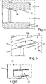
- the door rack 6 has a latching device 23 ( 4 and 8 ) on.
- the plate 8 is arranged latched to the base body 7 by the latching device 23 .
- the latching device 23 is formed with latching elements on the base body side in the receiving groove 18 .
- latching elements 24 on the base body side which are designed in particular as ramps, are designed to be integrated on the upper boundary wall 19 .
- the latching elements 24 on the base body side can, however, also be formed on the lower boundary wall 20 , for example.
- the latching elements 24 are in the form of raised elements which extend into the receiving groove 18 .
- FIG 5 is a perspective view of the partial section according to FIG 4 shown.
- the rear wall 9 has openings 25 at the points at which the locking elements 24 are formed, through which the demoulding of the locking elements 24 is simplified when the base body 7 is manufactured.
- the coupling structure 17b shown there and the guide groove 21 are practically non-overlapping when viewed in the depth direction. At most, a maximum degree of overlap is given by a delimiting web 26 of the coupling structure 17b, this coupling web 26 being the web region of the coupling structure 17b that is arranged furthest to the front when viewed in the depth direction.
- a simplified assembly of the door rack 6 on the inside 5 is made possible, because the door rack 6 can then also be mounted on the door 4 from above and the counter-coupling structure, in particular a cam, does not have to be between the guide groove 21 and the coupling structure 17b are threaded.
- a simple linear sliding movement from top to bottom can then take place by immersing the counter-coupling structure in the direction of arrow P1 into the coupling structure 17b, since the guide groove 21 is not in the way in this direction.
- the plate 8 is shown with surfaces formed by a top 27a and a bottom 27b.
- a plate-side latching element 28 of the latching device 23 is integrally formed in this upper side 27a and is therefore integrated.
- This latching element 28 on the plate is a latching recess, which is thus designed as a pre-specified depression in this upper side 28 .
- the shape of this plate-side latching element 28 is complementary to the shape of the base body-side latching element 24, so that in the latched state, the base body-side latching element 24 fits precisely against the plate-side latching element 28.
- the plate 8 is shown in a partial view and in section. It can be seen that the upper side 27a has a receiving trough 29 which is formed separately from the latching elements 28 designed as latching troughs. This receiving trough 29 creates a placement area or installation area for stored goods. Through this receiving trough 29, which is delimited by edge webs 30, a structure is created in the plate 8 itself, which prevents storage goods from slipping off the upper side 27a.
- Plate 8 is, like this, already in 2 was shown and explained, performed with lateral areas in the guide grooves 21 and 22 when inserting and then held in the assembled end position therein.
- a stable mounting of the plate 8 is made possible, even if it is arranged in a cantilevered manner towards the front.
Landscapes
- Engineering & Computer Science (AREA)
- Chemical & Material Sciences (AREA)
- Combustion & Propulsion (AREA)
- Physics & Mathematics (AREA)
- Mechanical Engineering (AREA)
- Thermal Sciences (AREA)
- General Engineering & Computer Science (AREA)
- Refrigerator Housings (AREA)
Applications Claiming Priority (2)
| Application Number | Priority Date | Filing Date | Title |
|---|---|---|---|
| DE102016225610.6A DE102016225610A1 (de) | 2016-12-20 | 2016-12-20 | Türabsteller mit einem an einem Grundkörper verrasteten Boden sowie Haushaltskältegerät mit einem Türabsteller |
| PCT/EP2017/082060 WO2018114405A1 (de) | 2016-12-20 | 2017-12-08 | Türabsteller mit einem an einem grundkörper verrasteten boden sowie haushaltskältegerät mit einem türabsteller |
Publications (2)
| Publication Number | Publication Date |
|---|---|
| EP3559569A1 EP3559569A1 (de) | 2019-10-30 |
| EP3559569B1 true EP3559569B1 (de) | 2022-04-06 |
Family
ID=60972179
Family Applications (1)
| Application Number | Title | Priority Date | Filing Date |
|---|---|---|---|
| EP17829147.2A Active EP3559569B1 (de) | 2016-12-20 | 2017-12-08 | Türabsteller mit einem an einem grundkörper verrasteten boden sowie haushaltskältegerät mit einem türabsteller |
Country Status (5)
| Country | Link |
|---|---|
| US (1) | US11112166B2 (pl) |
| EP (1) | EP3559569B1 (pl) |
| DE (1) | DE102016225610A1 (pl) |
| PL (1) | PL3559569T3 (pl) |
| WO (1) | WO2018114405A1 (pl) |
Families Citing this family (2)
| Publication number | Priority date | Publication date | Assignee | Title |
|---|---|---|---|---|
| CN109253581B (zh) * | 2017-07-12 | 2022-05-17 | 东芝生活电器株式会社 | 储物装置 |
| US11365930B2 (en) * | 2020-11-06 | 2022-06-21 | Bsh Home Appliances Corporation | Removable door bin height extender for refrigerator |
Family Cites Families (26)
| Publication number | Priority date | Publication date | Assignee | Title |
|---|---|---|---|---|
| US2201114A (en) * | 1938-05-28 | 1940-05-14 | Philco Refrigerator Company | Shelf and supports therefor |
| US2453387A (en) * | 1947-01-04 | 1948-11-09 | Philco Corp | Article supporting closure for cabinets |
| US2784044A (en) * | 1954-06-28 | 1957-03-05 | Gen Electric | Refrigerator door construction |
| US2780926A (en) * | 1955-01-13 | 1957-02-12 | Gen Motors Corp | Wall mounted refrigerating apparatus |
| GB1277699A (en) * | 1970-02-26 | 1972-06-14 | Gen Motors France | Refrigerator door liners having mountings for removable shelves |
| US3682521A (en) * | 1970-10-16 | 1972-08-08 | Gen Motors Corp | Adjustable door shelving |
| US3752553A (en) * | 1971-07-29 | 1973-08-14 | Amerock Corp | Drawer with snap-on front panel |
| US4921315A (en) * | 1987-12-21 | 1990-05-01 | Whirlpool Corporation | Refrigerator door structure |
| US5004305A (en) * | 1990-06-07 | 1991-04-02 | Amana Refrigeration Inc. | Refrigerator door shelves |
| US5647181A (en) * | 1994-10-11 | 1997-07-15 | Hunts; Larry David | Construction system and method for connecting rigid sheet-like panels together into doll houses, play houses, utility sheds and other structures |
| US5799803A (en) * | 1997-02-26 | 1998-09-01 | Nienkamper Furniture & Accessories Inc. | Cantilevered shelf and shelf bracket |
| US6824232B2 (en) * | 2002-01-10 | 2004-11-30 | Irene M Farmer | Bureau housing with baskets laundry system |
| US7200899B2 (en) * | 2003-11-17 | 2007-04-10 | Keter Plastic Ltd. | Method for connecting plastic elements to metal sheets and constructions |
| DE102004012497A1 (de) * | 2004-03-15 | 2005-10-06 | BSH Bosch und Siemens Hausgeräte GmbH | Kühlschrank mit Kühlgutabsteller |
| US8562089B2 (en) * | 2005-01-12 | 2013-10-22 | Whirlpool Corporation | Refrigerator shelf retainer and divider assembly for tall packages |
| US7681746B2 (en) * | 2005-04-12 | 2010-03-23 | Slingshot Marketing, Inc. | Multiple level product divider |
| US20080067910A1 (en) * | 2006-09-15 | 2008-03-20 | Thetford Corporation | Refrigerator shelving system with item retainer |
| DE102007005951A1 (de) * | 2007-02-06 | 2008-08-07 | BSH Bosch und Siemens Hausgeräte GmbH | Butterfach für ein Kältegerät |
| KR101631091B1 (ko) * | 2010-11-22 | 2016-06-17 | 삼성전자 주식회사 | 냉장고 및 그 저장용기 어셈블리 |
| DE102011006798A1 (de) * | 2011-04-05 | 2012-10-11 | BSH Bosch und Siemens Hausgeräte GmbH | Haushaltskältegerät mit einer Kühlgut-Aufnahmeeinrichtung sowie Verfahren zur Herstellung einer Kühlgut-Aufnahmeeinrichtung |
| US8616665B2 (en) * | 2011-05-24 | 2013-12-31 | Whirlpool Corporation | Door bin for a domestic refrigerator |
| WO2013050399A2 (en) * | 2011-10-03 | 2013-04-11 | Arcelik Anonim Sirketi | A shelf suitable for use on the cooling device door |
| TR201206627A1 (tr) * | 2012-06-06 | 2013-12-23 | Arcelik As | Soğutucu kapısında kullanılmaya uygun bir raf. |
| EP2808628B1 (en) * | 2013-05-28 | 2016-07-20 | LG Electronics Inc. | Vegetable container for refrigerators and refrigerator having the same |
| EP3967889B1 (en) * | 2013-09-16 | 2025-08-13 | Välinge Innovation AB | An assembled product |
| DE102016205705A1 (de) * | 2016-04-06 | 2017-10-12 | BSH Hausgeräte GmbH | Türabsteller für ein Haushaltskältegerät mit einem spezifischen Grundkörper und einem dazu separaten Zusatzteil sowie Haushaltskältegerät |
-
2016
- 2016-12-20 DE DE102016225610.6A patent/DE102016225610A1/de not_active Withdrawn
-
2017
- 2017-12-08 PL PL17829147.2T patent/PL3559569T3/pl unknown
- 2017-12-08 WO PCT/EP2017/082060 patent/WO2018114405A1/de not_active Ceased
- 2017-12-08 EP EP17829147.2A patent/EP3559569B1/de active Active
- 2017-12-08 US US16/466,182 patent/US11112166B2/en not_active Expired - Fee Related
Also Published As
| Publication number | Publication date |
|---|---|
| DE102016225610A1 (de) | 2018-06-21 |
| US20200072535A1 (en) | 2020-03-05 |
| US11112166B2 (en) | 2021-09-07 |
| WO2018114405A1 (de) | 2018-06-28 |
| PL3559569T3 (pl) | 2022-08-01 |
| EP3559569A1 (de) | 2019-10-30 |
Similar Documents
| Publication | Publication Date | Title |
|---|---|---|
| EP0764558A2 (de) | Einbau-Vorrichtung für Fahrzeuge | |
| WO2009071342A1 (de) | Kältegerät | |
| EP2220446B1 (de) | Kältegerät | |
| EP3559569B1 (de) | Türabsteller mit einem an einem grundkörper verrasteten boden sowie haushaltskältegerät mit einem türabsteller | |
| EP3228967B1 (de) | Türabsteller für ein haushaltskältegerät mit einem spezifischen grundkörper und einem dazu separaten zusatzteil sowie haushaltskältegerät | |
| EP3441704A1 (de) | Tür für ein Haushaltskältegerät mit spezifisch Befestiger Abdeckplatte sowie Haushaltskältegerät | |
| EP3758553B1 (de) | Möbel oder haushaltsgerät und verfahren zur montage einer funktionseinheit eines schubelements in einem möbel oder haushaltsgerät | |
| EP1926949B1 (de) | Gehäuse für ein haushaltsgerät | |
| DE4304484A1 (de) | Behälter, insbesondere schubladenartiger Behälter | |
| EP3951296A1 (de) | Trägereinrichtung mit spezifisch aufgeschnappter führungsschiene für eine lagerschale, lebensmittel-aufnahmebehälter, sowie verfahren | |
| EP3537077B1 (de) | Kühlgutabstellfach mit l-förmigen rahmen, tür sowie haushaltskältegerät | |
| EP3783288B1 (de) | Ablageboden mit dreiseitigem trägerahmen | |
| EP2217126B1 (de) | Haushaltsgerät | |
| EP3628945B1 (de) | Tür für ein haushaltsgerät mit frontseitiger dekorplatte und kantenschutzelement für eine randkante der dekorplatte, sowie haushaltsgerät | |
| DE102018127693B4 (de) | Transportbehälter zur Aufnahme von Werkzeug und Material, Transportbehältersystem und Regal-Behälter-System | |
| EP2276985B1 (de) | Kältegerät mit türabsteller | |
| EP3546859B1 (de) | Haushaltskältegerät mit einem befestigten plattenförmigen kühlgutträger | |
| DE19916621C2 (de) | Kühlgerät mit Tragboden | |
| DE102019214595A1 (de) | Lebensmittel-Aufnahmebehälter mit spezifisch geformter Klappe einer Lüftungseinrichtung, sowie Haushaltskältegerät | |
| EP4231875B1 (de) | Schubvorrichtung und verfahren zur montage einer schubvorrichtung | |
| DE102008041559B4 (de) | Kältegerät | |
| DE102022200426A1 (de) | Lebensmittel-Aufnahmebehälter mit einem an einer Koppelnocke befestigten Dekorteil, sowie Haushaltskältegerät | |
| DE102021208921A1 (de) | Beidseitig anschlagbare Tür mit spezifischen Montagebereich und optischer Griffseitenanzeige, sowie Haushaltskältegerät | |
| DE102022202522A1 (de) | Lebensmittel-Aufnahmebehälter mit einer Frontwand mit nutartiger Aufnahme für einen Deckel, sowie Haushaltskältegerät | |
| DE2721451A1 (de) | Schubkastenfuehrung fuer moebel |
Legal Events
| Date | Code | Title | Description |
|---|---|---|---|
| STAA | Information on the status of an ep patent application or granted ep patent |
Free format text: STATUS: UNKNOWN |
|
| STAA | Information on the status of an ep patent application or granted ep patent |
Free format text: STATUS: THE INTERNATIONAL PUBLICATION HAS BEEN MADE |
|
| PUAI | Public reference made under article 153(3) epc to a published international application that has entered the european phase |
Free format text: ORIGINAL CODE: 0009012 |
|
| STAA | Information on the status of an ep patent application or granted ep patent |
Free format text: STATUS: REQUEST FOR EXAMINATION WAS MADE |
|
| 17P | Request for examination filed |
Effective date: 20190722 |
|
| AK | Designated contracting states |
Kind code of ref document: A1 Designated state(s): AL AT BE BG CH CY CZ DE DK EE ES FI FR GB GR HR HU IE IS IT LI LT LU LV MC MK MT NL NO PL PT RO RS SE SI SK SM TR |
|
| AX | Request for extension of the european patent |
Extension state: BA ME |
|
| DAV | Request for validation of the european patent (deleted) | ||
| DAX | Request for extension of the european patent (deleted) | ||
| GRAP | Despatch of communication of intention to grant a patent |
Free format text: ORIGINAL CODE: EPIDOSNIGR1 |
|
| STAA | Information on the status of an ep patent application or granted ep patent |
Free format text: STATUS: GRANT OF PATENT IS INTENDED |
|
| INTG | Intention to grant announced |
Effective date: 20211130 |
|
| GRAS | Grant fee paid |
Free format text: ORIGINAL CODE: EPIDOSNIGR3 |
|
| GRAA | (expected) grant |
Free format text: ORIGINAL CODE: 0009210 |
|
| STAA | Information on the status of an ep patent application or granted ep patent |
Free format text: STATUS: THE PATENT HAS BEEN GRANTED |
|
| AK | Designated contracting states |
Kind code of ref document: B1 Designated state(s): AL AT BE BG CH CY CZ DE DK EE ES FI FR GB GR HR HU IE IS IT LI LT LU LV MC MK MT NL NO PL PT RO RS SE SI SK SM TR |
|
| REG | Reference to a national code |
Ref country code: GB Ref legal event code: FG4D Free format text: NOT ENGLISH |
|
| REG | Reference to a national code |
Ref country code: CH Ref legal event code: EP |
|
| REG | Reference to a national code |
Ref country code: AT Ref legal event code: REF Ref document number: 1481705 Country of ref document: AT Kind code of ref document: T Effective date: 20220415 |
|
| REG | Reference to a national code |
Ref country code: IE Ref legal event code: FG4D Free format text: LANGUAGE OF EP DOCUMENT: GERMAN |
|
| REG | Reference to a national code |
Ref country code: DE Ref legal event code: R096 Ref document number: 502017012936 Country of ref document: DE |
|
| REG | Reference to a national code |
Ref country code: LT Ref legal event code: MG9D |
|
| REG | Reference to a national code |
Ref country code: NL Ref legal event code: MP Effective date: 20220406 |
|
| PG25 | Lapsed in a contracting state [announced via postgrant information from national office to epo] |
Ref country code: NL Free format text: LAPSE BECAUSE OF FAILURE TO SUBMIT A TRANSLATION OF THE DESCRIPTION OR TO PAY THE FEE WITHIN THE PRESCRIBED TIME-LIMIT Effective date: 20220406 |
|
| PG25 | Lapsed in a contracting state [announced via postgrant information from national office to epo] |
Ref country code: SE Free format text: LAPSE BECAUSE OF FAILURE TO SUBMIT A TRANSLATION OF THE DESCRIPTION OR TO PAY THE FEE WITHIN THE PRESCRIBED TIME-LIMIT Effective date: 20220406 Ref country code: PT Free format text: LAPSE BECAUSE OF FAILURE TO SUBMIT A TRANSLATION OF THE DESCRIPTION OR TO PAY THE FEE WITHIN THE PRESCRIBED TIME-LIMIT Effective date: 20220808 Ref country code: NO Free format text: LAPSE BECAUSE OF FAILURE TO SUBMIT A TRANSLATION OF THE DESCRIPTION OR TO PAY THE FEE WITHIN THE PRESCRIBED TIME-LIMIT Effective date: 20220706 Ref country code: LT Free format text: LAPSE BECAUSE OF FAILURE TO SUBMIT A TRANSLATION OF THE DESCRIPTION OR TO PAY THE FEE WITHIN THE PRESCRIBED TIME-LIMIT Effective date: 20220406 Ref country code: HR Free format text: LAPSE BECAUSE OF FAILURE TO SUBMIT A TRANSLATION OF THE DESCRIPTION OR TO PAY THE FEE WITHIN THE PRESCRIBED TIME-LIMIT Effective date: 20220406 Ref country code: GR Free format text: LAPSE BECAUSE OF FAILURE TO SUBMIT A TRANSLATION OF THE DESCRIPTION OR TO PAY THE FEE WITHIN THE PRESCRIBED TIME-LIMIT Effective date: 20220707 Ref country code: FI Free format text: LAPSE BECAUSE OF FAILURE TO SUBMIT A TRANSLATION OF THE DESCRIPTION OR TO PAY THE FEE WITHIN THE PRESCRIBED TIME-LIMIT Effective date: 20220406 Ref country code: ES Free format text: LAPSE BECAUSE OF FAILURE TO SUBMIT A TRANSLATION OF THE DESCRIPTION OR TO PAY THE FEE WITHIN THE PRESCRIBED TIME-LIMIT Effective date: 20220406 Ref country code: BG Free format text: LAPSE BECAUSE OF FAILURE TO SUBMIT A TRANSLATION OF THE DESCRIPTION OR TO PAY THE FEE WITHIN THE PRESCRIBED TIME-LIMIT Effective date: 20220706 |
|
| PG25 | Lapsed in a contracting state [announced via postgrant information from national office to epo] |
Ref country code: RS Free format text: LAPSE BECAUSE OF FAILURE TO SUBMIT A TRANSLATION OF THE DESCRIPTION OR TO PAY THE FEE WITHIN THE PRESCRIBED TIME-LIMIT Effective date: 20220406 Ref country code: LV Free format text: LAPSE BECAUSE OF FAILURE TO SUBMIT A TRANSLATION OF THE DESCRIPTION OR TO PAY THE FEE WITHIN THE PRESCRIBED TIME-LIMIT Effective date: 20220406 Ref country code: IS Free format text: LAPSE BECAUSE OF FAILURE TO SUBMIT A TRANSLATION OF THE DESCRIPTION OR TO PAY THE FEE WITHIN THE PRESCRIBED TIME-LIMIT Effective date: 20220806 |
|
| REG | Reference to a national code |
Ref country code: DE Ref legal event code: R097 Ref document number: 502017012936 Country of ref document: DE |
|
| PG25 | Lapsed in a contracting state [announced via postgrant information from national office to epo] |
Ref country code: SM Free format text: LAPSE BECAUSE OF FAILURE TO SUBMIT A TRANSLATION OF THE DESCRIPTION OR TO PAY THE FEE WITHIN THE PRESCRIBED TIME-LIMIT Effective date: 20220406 Ref country code: SK Free format text: LAPSE BECAUSE OF FAILURE TO SUBMIT A TRANSLATION OF THE DESCRIPTION OR TO PAY THE FEE WITHIN THE PRESCRIBED TIME-LIMIT Effective date: 20220406 Ref country code: RO Free format text: LAPSE BECAUSE OF FAILURE TO SUBMIT A TRANSLATION OF THE DESCRIPTION OR TO PAY THE FEE WITHIN THE PRESCRIBED TIME-LIMIT Effective date: 20220406 Ref country code: EE Free format text: LAPSE BECAUSE OF FAILURE TO SUBMIT A TRANSLATION OF THE DESCRIPTION OR TO PAY THE FEE WITHIN THE PRESCRIBED TIME-LIMIT Effective date: 20220406 Ref country code: DK Free format text: LAPSE BECAUSE OF FAILURE TO SUBMIT A TRANSLATION OF THE DESCRIPTION OR TO PAY THE FEE WITHIN THE PRESCRIBED TIME-LIMIT Effective date: 20220406 Ref country code: CZ Free format text: LAPSE BECAUSE OF FAILURE TO SUBMIT A TRANSLATION OF THE DESCRIPTION OR TO PAY THE FEE WITHIN THE PRESCRIBED TIME-LIMIT Effective date: 20220406 |
|
| PGFP | Annual fee paid to national office [announced via postgrant information from national office to epo] |
Ref country code: TR Payment date: 20221205 Year of fee payment: 6 Ref country code: DE Payment date: 20221231 Year of fee payment: 6 |
|
| PLBE | No opposition filed within time limit |
Free format text: ORIGINAL CODE: 0009261 |
|
| STAA | Information on the status of an ep patent application or granted ep patent |
Free format text: STATUS: NO OPPOSITION FILED WITHIN TIME LIMIT |
|
| PGFP | Annual fee paid to national office [announced via postgrant information from national office to epo] |
Ref country code: PL Payment date: 20221202 Year of fee payment: 6 |
|
| 26N | No opposition filed |
Effective date: 20230110 |
|
| PG25 | Lapsed in a contracting state [announced via postgrant information from national office to epo] |
Ref country code: AL Free format text: LAPSE BECAUSE OF FAILURE TO SUBMIT A TRANSLATION OF THE DESCRIPTION OR TO PAY THE FEE WITHIN THE PRESCRIBED TIME-LIMIT Effective date: 20220406 |
|
| PG25 | Lapsed in a contracting state [announced via postgrant information from national office to epo] |
Ref country code: SI Free format text: LAPSE BECAUSE OF FAILURE TO SUBMIT A TRANSLATION OF THE DESCRIPTION OR TO PAY THE FEE WITHIN THE PRESCRIBED TIME-LIMIT Effective date: 20220406 |
|
| PGFP | Annual fee paid to national office [announced via postgrant information from national office to epo] |
Ref country code: IT Payment date: 20221230 Year of fee payment: 6 |
|
| REG | Reference to a national code |
Ref country code: CH Ref legal event code: PL |
|
| GBPC | Gb: european patent ceased through non-payment of renewal fee |
Effective date: 20221208 |
|
| REG | Reference to a national code |
Ref country code: BE Ref legal event code: MM Effective date: 20221231 |
|
| PG25 | Lapsed in a contracting state [announced via postgrant information from national office to epo] |
Ref country code: LU Free format text: LAPSE BECAUSE OF NON-PAYMENT OF DUE FEES Effective date: 20221208 |
|
| PG25 | Lapsed in a contracting state [announced via postgrant information from national office to epo] |
Ref country code: LI Free format text: LAPSE BECAUSE OF NON-PAYMENT OF DUE FEES Effective date: 20221231 Ref country code: IE Free format text: LAPSE BECAUSE OF NON-PAYMENT OF DUE FEES Effective date: 20221208 Ref country code: GB Free format text: LAPSE BECAUSE OF NON-PAYMENT OF DUE FEES Effective date: 20221208 Ref country code: CH Free format text: LAPSE BECAUSE OF NON-PAYMENT OF DUE FEES Effective date: 20221231 |
|
| PG25 | Lapsed in a contracting state [announced via postgrant information from national office to epo] |
Ref country code: FR Free format text: LAPSE BECAUSE OF NON-PAYMENT OF DUE FEES Effective date: 20221231 Ref country code: BE Free format text: LAPSE BECAUSE OF NON-PAYMENT OF DUE FEES Effective date: 20221231 |
|
| REG | Reference to a national code |
Ref country code: AT Ref legal event code: MM01 Ref document number: 1481705 Country of ref document: AT Kind code of ref document: T Effective date: 20221208 |
|
| PG25 | Lapsed in a contracting state [announced via postgrant information from national office to epo] |
Ref country code: HU Free format text: LAPSE BECAUSE OF FAILURE TO SUBMIT A TRANSLATION OF THE DESCRIPTION OR TO PAY THE FEE WITHIN THE PRESCRIBED TIME-LIMIT; INVALID AB INITIO Effective date: 20171208 |
|
| PG25 | Lapsed in a contracting state [announced via postgrant information from national office to epo] |
Ref country code: AT Free format text: LAPSE BECAUSE OF NON-PAYMENT OF DUE FEES Effective date: 20221208 |
|
| PG25 | Lapsed in a contracting state [announced via postgrant information from national office to epo] |
Ref country code: CY Free format text: LAPSE BECAUSE OF FAILURE TO SUBMIT A TRANSLATION OF THE DESCRIPTION OR TO PAY THE FEE WITHIN THE PRESCRIBED TIME-LIMIT Effective date: 20220406 Ref country code: AT Free format text: LAPSE BECAUSE OF NON-PAYMENT OF DUE FEES Effective date: 20221208 |
|
| PG25 | Lapsed in a contracting state [announced via postgrant information from national office to epo] |
Ref country code: MK Free format text: LAPSE BECAUSE OF FAILURE TO SUBMIT A TRANSLATION OF THE DESCRIPTION OR TO PAY THE FEE WITHIN THE PRESCRIBED TIME-LIMIT Effective date: 20220406 |
|
| PG25 | Lapsed in a contracting state [announced via postgrant information from national office to epo] |
Ref country code: MC Free format text: LAPSE BECAUSE OF FAILURE TO SUBMIT A TRANSLATION OF THE DESCRIPTION OR TO PAY THE FEE WITHIN THE PRESCRIBED TIME-LIMIT Effective date: 20220406 |
|
| PG25 | Lapsed in a contracting state [announced via postgrant information from national office to epo] |
Ref country code: MC Free format text: LAPSE BECAUSE OF FAILURE TO SUBMIT A TRANSLATION OF THE DESCRIPTION OR TO PAY THE FEE WITHIN THE PRESCRIBED TIME-LIMIT Effective date: 20220406 |
|
| REG | Reference to a national code |
Ref country code: DE Ref legal event code: R119 Ref document number: 502017012936 Country of ref document: DE |
|
| PG25 | Lapsed in a contracting state [announced via postgrant information from national office to epo] |
Ref country code: MT Free format text: LAPSE BECAUSE OF FAILURE TO SUBMIT A TRANSLATION OF THE DESCRIPTION OR TO PAY THE FEE WITHIN THE PRESCRIBED TIME-LIMIT Effective date: 20220406 |
|
| PG25 | Lapsed in a contracting state [announced via postgrant information from national office to epo] |
Ref country code: DE Free format text: LAPSE BECAUSE OF NON-PAYMENT OF DUE FEES Effective date: 20240702 |
|
| PG25 | Lapsed in a contracting state [announced via postgrant information from national office to epo] |
Ref country code: DE Free format text: LAPSE BECAUSE OF NON-PAYMENT OF DUE FEES Effective date: 20240702 |
|
| PG25 | Lapsed in a contracting state [announced via postgrant information from national office to epo] |
Ref country code: BG Free format text: LAPSE BECAUSE OF FAILURE TO SUBMIT A TRANSLATION OF THE DESCRIPTION OR TO PAY THE FEE WITHIN THE PRESCRIBED TIME-LIMIT Effective date: 20220406 |
|
| PG25 | Lapsed in a contracting state [announced via postgrant information from national office to epo] |
Ref country code: BG Free format text: LAPSE BECAUSE OF FAILURE TO SUBMIT A TRANSLATION OF THE DESCRIPTION OR TO PAY THE FEE WITHIN THE PRESCRIBED TIME-LIMIT Effective date: 20220406 |
|
| PG25 | Lapsed in a contracting state [announced via postgrant information from national office to epo] |
Ref country code: PL Free format text: LAPSE BECAUSE OF NON-PAYMENT OF DUE FEES Effective date: 20231208 |
|
| PG25 | Lapsed in a contracting state [announced via postgrant information from national office to epo] |
Ref country code: IT Free format text: LAPSE BECAUSE OF NON-PAYMENT OF DUE FEES Effective date: 20231208 |