EP3559569B1 - Door rack having a bottom latched on a basic body, and domestic refrigeration appliance having a door rack - Google Patents
Door rack having a bottom latched on a basic body, and domestic refrigeration appliance having a door rack Download PDFInfo
- Publication number
- EP3559569B1 EP3559569B1 EP17829147.2A EP17829147A EP3559569B1 EP 3559569 B1 EP3559569 B1 EP 3559569B1 EP 17829147 A EP17829147 A EP 17829147A EP 3559569 B1 EP3559569 B1 EP 3559569B1
- Authority
- EP
- European Patent Office
- Prior art keywords
- plate
- door rack
- door
- latching
- rear wall
- Prior art date
- Legal status (The legal status is an assumption and is not a legal conclusion. Google has not performed a legal analysis and makes no representation as to the accuracy of the status listed.)
- Active
Links
- 238000005057 refrigeration Methods 0.000 title claims description 16
- 210000003195 fascia Anatomy 0.000 claims 1
- 238000010168 coupling process Methods 0.000 description 26
- 238000005859 coupling reaction Methods 0.000 description 26
- 230000008878 coupling Effects 0.000 description 22
- 230000007774 longterm Effects 0.000 description 2
- 238000004140 cleaning Methods 0.000 description 1
- 239000003086 colorant Substances 0.000 description 1
- 230000000295 complement effect Effects 0.000 description 1
- 238000010276 construction Methods 0.000 description 1
- 230000000694 effects Effects 0.000 description 1
- 239000011521 glass Substances 0.000 description 1
- 238000002347 injection Methods 0.000 description 1
- 239000007924 injection Substances 0.000 description 1
- 238000009434 installation Methods 0.000 description 1
- 238000004519 manufacturing process Methods 0.000 description 1
- 239000000463 material Substances 0.000 description 1
- 239000002184 metal Substances 0.000 description 1
- 230000003287 optical effect Effects 0.000 description 1
Images


Classifications
-
- F—MECHANICAL ENGINEERING; LIGHTING; HEATING; WEAPONS; BLASTING
- F25—REFRIGERATION OR COOLING; COMBINED HEATING AND REFRIGERATION SYSTEMS; HEAT PUMP SYSTEMS; MANUFACTURE OR STORAGE OF ICE; LIQUEFACTION SOLIDIFICATION OF GASES
- F25D—REFRIGERATORS; COLD ROOMS; ICE-BOXES; COOLING OR FREEZING APPARATUS NOT OTHERWISE PROVIDED FOR
- F25D23/00—General constructional features
- F25D23/02—Doors; Covers
- F25D23/04—Doors; Covers with special compartments, e.g. butter conditioners
-
- F—MECHANICAL ENGINEERING; LIGHTING; HEATING; WEAPONS; BLASTING
- F25—REFRIGERATION OR COOLING; COMBINED HEATING AND REFRIGERATION SYSTEMS; HEAT PUMP SYSTEMS; MANUFACTURE OR STORAGE OF ICE; LIQUEFACTION SOLIDIFICATION OF GASES
- F25D—REFRIGERATORS; COLD ROOMS; ICE-BOXES; COOLING OR FREEZING APPARATUS NOT OTHERWISE PROVIDED FOR
- F25D25/00—Charging, supporting, and discharging the articles to be cooled
- F25D25/02—Charging, supporting, and discharging the articles to be cooled by shelves
-
- F—MECHANICAL ENGINEERING; LIGHTING; HEATING; WEAPONS; BLASTING
- F25—REFRIGERATION OR COOLING; COMBINED HEATING AND REFRIGERATION SYSTEMS; HEAT PUMP SYSTEMS; MANUFACTURE OR STORAGE OF ICE; LIQUEFACTION SOLIDIFICATION OF GASES
- F25D—REFRIGERATORS; COLD ROOMS; ICE-BOXES; COOLING OR FREEZING APPARATUS NOT OTHERWISE PROVIDED FOR
- F25D11/00—Self-contained movable devices, e.g. domestic refrigerators
-
- F—MECHANICAL ENGINEERING; LIGHTING; HEATING; WEAPONS; BLASTING
- F25—REFRIGERATION OR COOLING; COMBINED HEATING AND REFRIGERATION SYSTEMS; HEAT PUMP SYSTEMS; MANUFACTURE OR STORAGE OF ICE; LIQUEFACTION SOLIDIFICATION OF GASES
- F25D—REFRIGERATORS; COLD ROOMS; ICE-BOXES; COOLING OR FREEZING APPARATUS NOT OTHERWISE PROVIDED FOR
- F25D23/00—General constructional features
- F25D23/02—Doors; Covers
- F25D23/028—Details
Definitions
- the invention relates to a door rack for a household refrigeration appliance.
- the door rack has a base body which is designed to accommodate stored goods.
- the invention also relates to a household refrigeration appliance with at least one such door maker.
- Door compartments can be designed in one piece or in several pieces.
- multi-part configurations of door racks which are thus made up of at least two separate components, it is usually provided that the door rack is covered on the side and also on the front by boundary walls. Accessibility in such configurations is then only possible via an opening at the top, via which storage goods can be brought into the door rack or removed from it. This limits accessibility and user-friendliness.
- WO 2013/182429 A1 and WO 2013/050399 A2 disclose a door storage compartment having a body having 2 opposed side walls, a rear wall and a front wall extending between the side walls, and a storage shelf.
- a support member is attached to the front wall and extends partially across the shelf so that the shelf is fixed to the body.
- DE 10 2011 006 798 A1 discloses a household appliance, having a heat-insulated inner container with a coolable interior, a heat-insulated door leaf provided for closing the interior, with an outer side and an inner side facing the interior, and at least one refrigerated goods receiving device having the outer walls, the refrigerated goods receiving device having a shaped metal part, which forms at least two of the outer walls and that a holding device has, on which another of the outer walls is mounted.
- the door rack has a base body which is designed to accommodate stored goods.
- the base body has a rear wall and an upper bracket which faces away from the rear wall of the base body and is oriented towards the front.
- the bracket is designed to be continuous and without interruption, and its two ends open into specific areas of the base body.
- the door rack has a plate that is separate from the base body and serves as the bottom of the door rack on the base body is attachable.
- a latching device is designed as the fastening device, so that this base is latched to the base body.
- the position of the bracket as the upper bracket also promotes this mechanical stability, since it has an advantageous effect on the stability of the door compartment in connection with the plate, which is arranged on a lower area of the base body.
- By latching the plate to the base body it is also attached to it in a non-destructively detachable manner. It can also be assembled and disassembled quickly.
- the latching also enables the plate to be attached to the base body in a secure position.
- the design as a separate and thus removable plate is also very advantageous for cleaning purposes.
- the door rack not only allows storage goods to be removed or inserted into the door rack via an upper opening defined by the rear wall and the upper bracket, but also allows storage goods to be removed or inserted into the door rack via the reach-through area. It is thus also possible for storage goods to be removed from the side or the front and inserted into the door rack or out of the door rack. Nevertheless, a limitation is created by the upper bracket, which prevents stored goods from simply slipping down or falling out of the door racks.
- the plate is arranged cantilevered in its end position on the front side facing away from the rear wall or on a relevant front area. This means that it is not covered or supported by additional components in this front area and also in some areas on the side areas. At this front area and on In some side areas, the panel is thus designed and arranged as a visible component of the door rack.
- Such a configuration further reduces the number of components and, on the other hand, maximizes accessibility to the door compartment via the reach-through area. Since the panel is of very flat construction, the distance from the panel to the upper bracket is at a maximum and is not reduced by other additional components that would be arranged on the front and sides of the panel.
- a receiving groove to be formed on a front side of the rear wall facing the receiving volume of the door compartment, in which groove a rear edge of the panel extends in the end position arranged on the base body.
- the base body is made in one piece from plastic, in particular produced as an injection molded part.
- the receiving groove is bounded at the top by the upper boundary wall and at the bottom by a lower boundary wall.
- the lower boundary wall can preferably be flush with a lower edge of the rear wall.
- the latching elements of the latching device on the body side are designed as raised ramps. This is very advantageous in that the plate does not face an abrupt step on its way into the receiving groove, it does not have to be overcome to latch, but here the ramp provides a starting slope over which the plate can slide along and then close the rear of the ramp snap behind and thus form the locking connection.
- the rear wall preferably has an opening in each case in the region of the latching elements. This favors the one-piece production from plastic, since demoulding is simplified. In particular, the demoulding of the latching elements is then simplified and significantly improved with regard to the shape precision of these latching elements.
- the openings preferably have a width that corresponds to the width of the respective adjacent ones Corresponds to locking elements. In this width direction, the openings are formed exactly at the points at which the respective latching elements are also formed.
- the base body preferably has side walls which open onto the rear wall.
- these side walls preferably only extend over part of the entire extent of the door compartment viewed in the depth direction of the door compartment.
- the upper bracket extends forwardly as viewed from these side walls. The free ends of the upper bracket thus open onto these side walls.
- the base body thus has side walls which extend only partially over the depth of the bracket measured in the depth direction of the door compartment and open onto the rear wall.
- the receiving groove opens out onto these opposite side walls.
- the receiving groove thus extends over the entire width of the rear wall measured in the width direction.
- Such a configuration increases the stability of the base body.
- a full-area delimitation formed over the entire height of the door rack is not only realized by the rear wall, but also over a partial area of the door rack viewed in the depth direction, in that these side walls extend accordingly.
- the side walls also preferably extend over the entire height of the rear wall.
- the reach-through area thus extends at the front and on the side areas, being formed on the side areas only up to the front edges of the side walls.
- guide grooves for the plate are formed on the insides of these side walls.
- Such a configuration in addition to the already mentioned receiving groove, creates a further mechanical coupling that is locally separated and objected to, and by means of which the plate is held even more stably.
- these guide grooves are offset to the front when viewed in the depth direction and spaced apart from the receptacles, and the guide grooves are open to the front at the front edges of the side walls.
- the receiving groove is adjacent to a lower edge of the rear wall, but is nevertheless delimited from below by a delimiting wall.
- the plate-side latching elements are integrated in the plate and are thus formed in one piece with it. This also saves assembly work and allows the latching elements to remain securely in position over the long term.
- the latching elements on the plate are preferably designed as latching depressions. This is advantageous in that no elements are formed on the plate that protrude upwards or out of the plane of the plate, which other components or a user could bump into when inserting or removing the plate. In addition, such a negative shape of the plate-side latching elements also means that a protected position of these latching elements in the panel is achieved.
- these plate-side latching elements are formed on an upper side of the plate, with the upper side facing the upper bracket when the plate is mounted on the base body. In such a configuration, it is then also advantageous if the latching elements on the base body side are formed on the upper boundary wall of the receiving groove.
- the snap-in elements on the base body are formed on a lower boundary wall and the snap-in elements on the plate are formed on an underside of this plate.
- the upper bracket has a fastening device for fastening a panel that covers the bracket at least in regions and is separate from the upper bracket.
- the panel can be designed as a decorative element.
- the plate is made of real glass.
- Coupling structures can be formed on the preferably present side walls of the base body on the outsides facing away from the receiving volume of the door compartment, with which the base body and thus also the entire door compartment can be attached to counter-coupling structures of a door of a household refrigeration appliance.
- such a coupling structure is formed on the base body as an upside-down U-shape.
- the coupling structure formed on the outside of the side walls is formed further back than the preferably present guide grooves on the inner sides of the side walls facing the storage volume.
- the guide groove and the coupling structure are arranged so that they overlap at most over a delimiting web which delimits the coupling structure.
- this coupling web is the one furthest to the front and is therefore the coupling web facing the guide groove.
- the door rack has a receiving trough on an upper side of the panel facing the upper bracket.
- a sink simplifies the setting up of stored goods, since they cannot slip out of the door compartment through the reach-through area.
- Such a design of the plate is thus created on the plate itself and integrated thereon, so to speak, a border that forms a slip protection for stored goods placed on it.
- the invention also relates to a household refrigeration appliance with a housing and a storage space for food formed therein, which can be closed by a door.
- the household refrigeration appliance has at least one door compartment according to the above aspect or an advantageous embodiment thereof, which is arranged in particular on an inner side of the door facing the receiving space.
- top”, “bottom”, “front”, “back”, “horizontal”, “vertical”, “depth direction”, “width direction”, “height direction” are the intended use and intended arrangement of the device and a positions and orientations given to the observer standing in front of the device and looking in the direction of the device.
- FIG. 1 is a perspective view of a household refrigeration appliance 1, which can be, for example, a refrigerator or a freezer or a fridge-freezer combination device, and which is designed for storing and preserving food.
- the household refrigeration appliance 1 has a housing 2 in which a receiving space 3 for food is formed.
- the receiving space 3 can be closed by a door 4 at the front.
- At least one door compartment 6 is arranged on an inner side 5 of the door 4, which faces the receiving space 3 when the door 4 is closed.
- the door compartment 6 has a base body 7 .
- the base body 7 is preferably made in one piece, in particular made of plastic.
- the door rack 6 also has a plate 8 designed as the bottom of the door rack 6 , which is a separate component from the base body 7 . In 2 is the mounted one The final state of the plate 8 on the base body 7 is shown. The plate 8 is latched to the base body 7 by a latching device.
- the door compartment 6 is designed in such a way that the panel 8 extends over the entire width of the base body 7 in the width direction (x-direction), which also corresponds to the width direction of the household refrigeration appliance 1 .
- the base body 7, which in 3 shown separately from the plate 8 has a rear wall 9 which delimits a receiving volume 10 of the door rack 6 to the rear.
- the base body 7 also has side walls 11 and 12 which open onto the rear wall 9 .
- the base body 7 also has an upper bracket 13 which is U-shaped. This upper bracket 13 in particular forms the upper edge and thus also the upper end of the base body 7 and thus preferably also of the door compartment 6.
- This upper bracket 13 opens with its ends on the side walls 11 and 12, in particular on front edges 11a and 12a of the side walls 11 and 12.
- the side walls 11 and 12 therefore only partially extend over the extent of the base body 7.
- the bracket 13 thus extends starting from these front edges 11a and 11a facing away from the rear wall 9 12a of the side walls 11 and 12 to the front.
- the upper bracket 13 is designed as an open channel, in particular U-shaped, in a cross section perpendicular to its longitudinal axis. This configuration increases its mechanical stability and torsional rigidity. In addition, such a design makes it advantageous to form a fastening device 14 in this channel area, with a cover (not shown) and separate from the base body 7 or a decorative element being able to be fastened to this fastening device 14 .
- the upper bracket 13 is at least partially covered by this panel to the front and to the side.
- the door rack 6 has a loading opening 15 which is open at the top and is delimited by the rear wall 14, the side walls 11 and 12 and the upper bracket 13. Stored goods can be introduced into or removed from the receiving volume 10 through this loading opening 15 .
- the door rack 6 has a reach-through area 16 on the front and side. This is limited in the height direction (y-direction) by the upper bracket 13 from above and by the plate 8 from below. Through this reach-through area 16 it is also possible to reach into the receiving volume 10 from the side and from the front and the removal of stored goods or the introduction of stored goods can also take place via this reach-through area 16 .
- the reach-through area 16 is therefore not covered by a component.
- the plate 8 is designed to be exposed at its front edge 8a and partially at side edges 8b and 8c and is therefore arranged in a cantilevered manner towards the front and to the side in this respect. This means that the plate 8 is not covered by another component at the front and at these partial areas of the side areas. In this respect, the plate 8 is then arranged in a freely floating manner towards the front. It is therefore no longer supported or otherwise enclosed in these areas from below or from above.
- the base body 7, as also shown in 3 is shown, has a coupling structure on the outer sides 11b and 12b facing away from the receiving volume 10, from which in 2 and 3 only the coupling structure 17a can be seen on the outside 12b.
- This coupling structure 17a is designed as a raised web which has an inverted U-shape.
- the door compartment 6 can be attached to a counter-coupling structure on the inside 5 via this coupling structure 17a.
- a receiving groove 18 is formed in the base body 7 .
- the receiving groove 18 is delimited by an upper boundary wall 19 and a lower boundary wall 20 .
- the receiving groove 18 is formed on the rear wall 9 in the lower area.
- the receiving groove 18 extends over the entire width of the rear wall 9 and opens out on the inner sides 11c and 12c of the side walls 11 and 12.
- the receiving groove 18 is designed to be open towards the front and, as in FIG 2 can be seen, for receiving the rear edge of the plate 8 is formed.
- On the inside 11c of the side wall 11 there is also a guide groove 21 which, viewed in the depth direction, ends in front of the receiving groove 18 but is open at the front edge 11a of the side wall 11 .
- a similarly designed guide groove 22 is formed on the inside 12c of the side wall 12 .
- the door rack 6 has a latching device 23 ( 4 and 8 ) on.
- the plate 8 is arranged latched to the base body 7 by the latching device 23 .
- the latching device 23 is formed with latching elements on the base body side in the receiving groove 18 .
- latching elements 24 on the base body side which are designed in particular as ramps, are designed to be integrated on the upper boundary wall 19 .
- the latching elements 24 on the base body side can, however, also be formed on the lower boundary wall 20 , for example.
- the latching elements 24 are in the form of raised elements which extend into the receiving groove 18 .
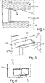
- FIG 5 is a perspective view of the partial section according to FIG 4 shown.
- the rear wall 9 has openings 25 at the points at which the locking elements 24 are formed, through which the demoulding of the locking elements 24 is simplified when the base body 7 is manufactured.
- the coupling structure 17b shown there and the guide groove 21 are practically non-overlapping when viewed in the depth direction. At most, a maximum degree of overlap is given by a delimiting web 26 of the coupling structure 17b, this coupling web 26 being the web region of the coupling structure 17b that is arranged furthest to the front when viewed in the depth direction.
- a simplified assembly of the door rack 6 on the inside 5 is made possible, because the door rack 6 can then also be mounted on the door 4 from above and the counter-coupling structure, in particular a cam, does not have to be between the guide groove 21 and the coupling structure 17b are threaded.
- a simple linear sliding movement from top to bottom can then take place by immersing the counter-coupling structure in the direction of arrow P1 into the coupling structure 17b, since the guide groove 21 is not in the way in this direction.
- the plate 8 is shown with surfaces formed by a top 27a and a bottom 27b.
- a plate-side latching element 28 of the latching device 23 is integrally formed in this upper side 27a and is therefore integrated.
- This latching element 28 on the plate is a latching recess, which is thus designed as a pre-specified depression in this upper side 28 .
- the shape of this plate-side latching element 28 is complementary to the shape of the base body-side latching element 24, so that in the latched state, the base body-side latching element 24 fits precisely against the plate-side latching element 28.
- the plate 8 is shown in a partial view and in section. It can be seen that the upper side 27a has a receiving trough 29 which is formed separately from the latching elements 28 designed as latching troughs. This receiving trough 29 creates a placement area or installation area for stored goods. Through this receiving trough 29, which is delimited by edge webs 30, a structure is created in the plate 8 itself, which prevents storage goods from slipping off the upper side 27a.
- Plate 8 is, like this, already in 2 was shown and explained, performed with lateral areas in the guide grooves 21 and 22 when inserting and then held in the assembled end position therein.
- a stable mounting of the plate 8 is made possible, even if it is arranged in a cantilevered manner towards the front.
Description
Die Erfindung betrifft einen Türabsteller für ein Haushaltskältegerät. Der Türabsteller weist einen Grundkörper auf, welcher zur Aufnahme von Lagergütern ausgebildet ist. Des Weiteren betrifft die Erfindung auch ein Haushaltskältegerät mit zumindest einem derartigen Türbasteller.The invention relates to a door rack for a household refrigeration appliance. The door rack has a base body which is designed to accommodate stored goods. Furthermore, the invention also relates to a household refrigeration appliance with at least one such door maker.
Türabsteller für Haushaltskältegeräte sind in vielfältigen Ausgestaltungen bekannt.Door racks for household refrigeration appliances are known in many different configurations.
Türabsteller können einteilig oder auch mehrteilig ausgebildet sein. Bei mehrteiligen Ausgestaltungen von Türbastellern, die somit aus zumindest zwei separaten Komponenten aufgebaut sind, ist es üblicherweise vorgesehen, dass der Türabsteller seitlich und auch frontseitig durch Begrenzungswände abgedeckt ist. Die Zugänglichkeit bei derartigen Ausgestaltungen ist dann nur über eine Öffnung nach oben möglich, über welche Lagergüter in den Türabsteller eingebracht werden können oder daraus entnommen werden können. Zugänglichkeit und Nutzerfreundlichkeit ist dadurch eingeschränkt.Door compartments can be designed in one piece or in several pieces. In the case of multi-part configurations of door racks, which are thus made up of at least two separate components, it is usually provided that the door rack is covered on the side and also on the front by boundary walls. Accessibility in such configurations is then only possible via an opening at the top, via which storage goods can be brought into the door rack or removed from it. This limits accessibility and user-friendliness.
Es ist Aufgabe der vorliegenden Erfindung einen Türabsteller zu schaffen, welcher bezüglich seiner Zugänglichkeit variabler ist andererseits jedoch in seiner mehrteiligen Ausgestaltung mechanisch stabil aufgebaut ist.It is the object of the present invention to create a door rack which is more variable in terms of its accessibility but which, on the other hand, is constructed in a mechanically stable manner in its multi-part configuration.
Diese Aufgabe wird durch einen Türabsteller und ein Haushaltskältegeräte gemäß den unabhängigen Ansprüchen gelöst.This object is achieved by a door rack and a household refrigeration appliance according to the independent claims.
Ein Aspekt der Erfindung betrifft einen Türabsteller für ein Haushaltskältegerät. Der Türabsteller weist einen Grundkörper auf, welcher zur Aufnahme von Lagergütern ausgebildet ist. Der Grundkörper weist eine Rückwand und einen der Rückwand des Grundkörpers abgewandten und nach vorne orientierten oberen Bügel auf. Der Bügel ist zusammenhängend und unterbrechungsfrei ausgebildet und mündet mit seinen beiden Enden an spezifische Bereiche des Grundkörpers an. Der Türabsteller weist eine zum Grundkörper separate Platte auf, die als Boden des Türabstellers an dem Grundkörper befestigbar ist. Als Befestigungsvorrichtung ist eine Rastvorrichtung ausgebildet, sodass dieser Boden an dem Grundkörper verrastet ist. In der in dem Grundkörper angeordneten Endposition der Platte ist in Höhenrichtung und somit in vertikaler Richtung des Türabstellers betrachtet zwischen dem Bügel und der Platte ein unverdeckter und freiliegender und somit dauerhaft freibleibender Durchgriffsbereich ausgebildet. In diesen montierten Zustand ist somit die Platte beabstandet zu diesem oberen Bügel ausgebildet und es kann von außen durch den Durchgriffsbereich hindurchgegriffen werden. Durch eine derartige Ausgestaltung wird ein Türabsteller geschaffen, der mehrteilig aufgebaut ist und dennoch in der Bauteilzahl minimiert ist. Durch die spezifische Ausgestaltung des Grundkörpers ist dieser auch mechanisch stabil und in sich verwindungssteif gestaltet. Insbesondere wird dies auch durch den Bügel ermöglicht. Auch die Position des Bügels als oberer Bügel begünstigt diese mechanische Stabilität zusätzlich, da er in Verbindung mit der Platte, die an einem unteren Bereich des Grundkörpers angeordnet ist, die Stabilität des Türabstellers vorteilhaft beeinflusst. Durch die Verrastung der Platte an dem Grundkörper ist diese auch zerstörungsfrei lösbar daran befestigt. Damit kann sie auch schnell montiert und demontiert werden. Durch die Verrastung ist auch ein positionssicheres Anbringen der Platte an dem Grundkörper ermöglicht. Die Ausgestaltung als separate und somit entnehmbare Platte ist auch für Reinigungszwecke sehr vorteilhaft.One aspect of the invention relates to a door rack for a household refrigeration appliance. The door rack has a base body which is designed to accommodate stored goods. The base body has a rear wall and an upper bracket which faces away from the rear wall of the base body and is oriented towards the front. The bracket is designed to be continuous and without interruption, and its two ends open into specific areas of the base body. The door rack has a plate that is separate from the base body and serves as the bottom of the door rack on the base body is attachable. A latching device is designed as the fastening device, so that this base is latched to the base body. In the end position of the panel arranged in the base body, viewed in the height direction and thus in the vertical direction of the door rack, an uncovered and exposed and thus permanently exposed reach-through area is formed between the bracket and the panel. In this mounted state, the plate is thus formed at a distance from this upper bracket and it is possible to reach through the reach-through area from the outside. Such a configuration creates a door rack that is constructed in several parts and yet has a minimized number of components. Due to the specific design of the base body, it is also mechanically stable and inherently torsion-resistant. In particular, this is also made possible by the bracket. The position of the bracket as the upper bracket also promotes this mechanical stability, since it has an advantageous effect on the stability of the door compartment in connection with the plate, which is arranged on a lower area of the base body. By latching the plate to the base body, it is also attached to it in a non-destructively detachable manner. It can also be assembled and disassembled quickly. The latching also enables the plate to be attached to the base body in a secure position. The design as a separate and thus removable plate is also very advantageous for cleaning purposes.
Darüber hinaus ermöglicht der Türabsteller nicht nur das Entnehmen oder Einfügen von Lagergütern in den Türabsteller über eine obere Öffnung, die durch die Rückwand und den oberen Bügel begrenzt ist, sondern ermöglicht auch das Entnehmen oder Einfügen von Lagergütern in den Türabsteller über den Durchgriffsbereich. Es kann somit auch ein seitliches oder frontseitiges Entnehmen und Einfügen von Lagergütern in den Türabsteller beziehungsweise aus dem Türabsteller heraus erfolgen. Dennoch ist durch den oberen Bügel eine Begrenzung geschaffen, durch die ein einfaches Herunterrutschen oder Herausfallen von Lagergütern aus den Türabstellern vermieden ist.In addition, the door rack not only allows storage goods to be removed or inserted into the door rack via an upper opening defined by the rear wall and the upper bracket, but also allows storage goods to be removed or inserted into the door rack via the reach-through area. It is thus also possible for storage goods to be removed from the side or the front and inserted into the door rack or out of the door rack. Nevertheless, a limitation is created by the upper bracket, which prevents stored goods from simply slipping down or falling out of the door racks.
In einer vorteilhaften Ausführung ist die Platte an der zur Rückwand abgewandten Vorderseite beziehungsweise an einem diesbezüglichen vorderen Bereich freikragend in ihrer Endposition angeordnet. Dies bedeutet, dass sie an diesem frontseitigen Bereich und auch bereichsweise an Seitenbereichen nicht durch zusätzliche weitere Komponenten abgedeckt oder gestützt ist. An diesem frontseitigen Bereich und an teilweisen Seitenbereichen ist die Platte somit als Sichtbauteil des Türabstellers ausgebildet und angeordnet. Durch eine derartige Ausgestaltung wird die Bauteilzah nochmals reduziert und andererseits die Zugänglichkeit zum Türabsteller über den Durchgriffsbereich maximiert. Da die Platte sehr flachbauend aufgebaut ist, ist der Abstand von der Platte zu dem oberen Bügel maximal und wird nicht durch andere zusätzliche Komponenten, die an der Platte fronseitig und seitlich angeordnet wären, reduziert. Darüber hinaus ist auch ein beruhigter optischer Eindruck geschaffen, da die Platte einen sehr filigranen Eindruck hinterlässt und somit mit ihrem Frontrand und Teilen der Seitenränder freiliegt und erkannt werden kann. Gerade dann, wenn die Platte auch materiell spezifiziert ist können diese Spezifikationen uneingeschränkt in Erscheinung treten und werden nicht anderweitig verdeckt.In an advantageous embodiment, the plate is arranged cantilevered in its end position on the front side facing away from the rear wall or on a relevant front area. This means that it is not covered or supported by additional components in this front area and also in some areas on the side areas. At this front area and on In some side areas, the panel is thus designed and arranged as a visible component of the door rack. Such a configuration further reduces the number of components and, on the other hand, maximizes accessibility to the door compartment via the reach-through area. Since the panel is of very flat construction, the distance from the panel to the upper bracket is at a maximum and is not reduced by other additional components that would be arranged on the front and sides of the panel. In addition, a calmer optical impression is also created, since the plate leaves a very filigree impression and its front edge and parts of the side edges are therefore exposed and can be recognized. Especially when the plate is also specified in terms of material, these specifications can appear without restriction and are not otherwise covered up.
Es ist vorgesehen, dass an einer dem Aufnahmevolumen des Türabstellers zugwandten Vorderseite der Rückwand eine Aufnahmenut ausgebildet ist, in welcher sich ein hinterer Rand der Platte in an den Grundkörper angeordneter Endposition hinein erstreckt. Dies ist eine sehr vorteilhafte Ausführung da somit die Platte sehr genau und sicher positioniert werden kann. Ein derartiger Schlitz in Form der Aufnahmenut ermöglicht ein zielsicheres Anbringen der Platte an dem Grundkörper und ein dauerhaft sicheres Halten.Provision is made for a receiving groove to be formed on a front side of the rear wall facing the receiving volume of the door compartment, in which groove a rear edge of the panel extends in the end position arranged on the base body. This is a very advantageous embodiment because the plate can be positioned very precisely and securely. Such a slot in the form of the receiving groove enables the plate to be attached to the base body in a targeted manner and held securely in the long term.
Es ist vorgesehen, dass grundkörperseitige Rastelemente der Rastvorrichtung in der Aufnahmenut ausgebildet sind. Dadurch wird ein Konzept geschaffen, welches einerseits eine zielgerichtete Verrastung ermöglicht, andererseits die mechanischen Halterungen in Form der Rastelemente einerseits und der Aufnahmenut andererseits örtlich zusammenfasst, sodass auch hier eine sehr bauraumsparende Ausgestaltung ermöglicht ist. Durch diese Kombination wird bei einem Einsetzen der Platte in den Grundkörper automatisch dann auch sicher und zuverlässig das Verrasten erreicht, wenn die Platte mit ihrem unteren Rand in die Aufnahmenut eingeschoben beziehungsweise eingesteckt wird. Darüber hinaus sind die Rastelemente, die an dem Grundkörper ausgebildet sind, dann auch im gewissen Maße geschützt angeordnet und können somit auch vor unerwünschten anderweitigem Anstoßen geschützt werden, sodass sie auch dauerhaft vor Beschädigungen geschützt werden und somit ihre Funktionalität dauerhaft hoch ist. Vorzugsweise ist vorgesehen, dass die Aufnahmenut eine obere Begrenzungswand aufweist, an welcher grundkörperseitige Rastelemente einstückig angeformt beziehungsweise ausgebildet sind. Dadurch können Rastelemente positionsgenau ausgebildet werden und zusätzlicher Montageaufwand ist eingespart.Provision is made for latching elements of the latching device on the body side to be formed in the receiving groove. This creates a concept which on the one hand enables targeted latching and on the other hand combines the mechanical mounts in the form of the latching elements on the one hand and the receiving groove on the other hand, so that a very space-saving design is also made possible here. With this combination, when the plate is inserted into the base body, the latching is automatically also achieved safely and reliably when the plate is pushed or plugged into the receiving groove with its lower edge. In addition, the latching elements that are formed on the base body are then also arranged protected to a certain extent and can thus also be protected against other unwanted impacts, so that they are also permanently protected against damage and their functionality is therefore permanently high. Provision is preferably made for the receiving groove to have an upper boundary wall, on which latching elements on the base body side are molded or formed in one piece. As a result, latching elements can be formed with a precise position and additional assembly work is saved.
Insbesondere ist der Grundkörper einstückig aus Kunststoff ausgebildet, insbesondere als Spritzgussteil hergestellt.In particular, the base body is made in one piece from plastic, in particular produced as an injection molded part.
Die Aufnahmenut ist nach oben hin durch die obere Begrenzungswand und nach unten hin durch eine untere Begrenzungswand begrenzt. Die untere Begrenzungswand kann vorzugsweise bündig mit einem unteren Rand der Rückwand ausgebildet sein. Dadurch wird auch im Hinblick auf die Positionierung der Platte ein maximal weites nach unten Anordnen der Platte an dem Grundkörper ermöglicht, wodurch das Aufnahmevolumen des Türabstellers maximiert ist und auch ein Abstand zwischen der Platte und dem oberen Bügel maximiert ist, sodass der Durchgriffsbereich sehr vorteilhaft zum Hindurchgreifen mit einer Hand eines Nutzers gestaltet ist.The receiving groove is bounded at the top by the upper boundary wall and at the bottom by a lower boundary wall. The lower boundary wall can preferably be flush with a lower edge of the rear wall. With regard to the positioning of the panel, this also enables the panel to be arranged as far downwards as possible on the base body, whereby the storage volume of the door compartment is maximized and a distance between the panel and the upper bracket is also maximized, so that the reach-through area is very advantageous for Reaching through with a hand of a user is designed.
Vorzugsweise ist vorgesehen, dass die grundkörperseitigen Rastelemente der Rastvorrichtung als erhabene Rampen ausgebildet sind. Die ist dahingehend sehr vorteilhaft, dass dann die Platte auf ihrem Einschubweg in die Aufnahmenut keiner abrupten Stufe gegenübersteht, sie zum Verrasten überwinden muss, sondern hier durch die Rampe eine Anlaufschräge bereitsteht, über welche dann die Platte entlang gleiten kann, um dann die Rampenrückseite zu hinterschnappen und somit die Rastverbindung auszubilden.Provision is preferably made for the latching elements of the latching device on the body side to be designed as raised ramps. This is very advantageous in that the plate does not face an abrupt step on its way into the receiving groove, it does not have to be overcome to latch, but here the ramp provides a starting slope over which the plate can slide along and then close the rear of the ramp snap behind and thus form the locking connection.
Vorzugsweise weist die Rückwand im Bereich der Rastelemente jeweils eine Durchbrechung auf. Dadurch ist gerade die einstückige Herstellung aus Kunststoff begünstigt, da eine Entformung vereinfacht ist. Insbesondere die Entformung der Rastelemente ist dann vereinfacht und bezüglich der Formpräzision dieser Rastelemente wesentlich begünstigt.The rear wall preferably has an opening in each case in the region of the latching elements. This favors the one-piece production from plastic, since demoulding is simplified. In particular, the demoulding of the latching elements is then simplified and significantly improved with regard to the shape precision of these latching elements.
Vorzugsweise weisen die Durchbrechungen in Breitenrichtung des Türabstellers betrachtet eine Breite auf, die der Breite der jeweils benachbart dazu befindlichen Rastelemente entspricht. In dieser Breitenrichtung sind die Durchbrechungen genau an den Stellen ausgebildet, an denen auch die jeweiligen Rastelemente ausgebildet sind.Viewed in the width direction of the door compartment, the openings preferably have a width that corresponds to the width of the respective adjacent ones Corresponds to locking elements. In this width direction, the openings are formed exactly at the points at which the respective latching elements are also formed.
Vorzugsweise weist der Grundkörper Seitenwände auf, die an die Rückwand anmünden. Diese Seitenwände erstrecken sich vorzugsweise jedoch nur über einen Teil des gesamten Ausmaßes des Türabstellers in Tiefenrichtung des Türabstellers betrachtet. Somit erstreckt sich in einer vorteilhaften Ausführung der obere Bügel von diesen Seitenwänden betrachtet nach vorne hin. Der obere Bügel mündet mit seinen freien Enden somit an diese Seitenwände.The base body preferably has side walls which open onto the rear wall. However, these side walls preferably only extend over part of the entire extent of the door compartment viewed in the depth direction of the door compartment. Thus, in an advantageous embodiment, the upper bracket extends forwardly as viewed from these side walls. The free ends of the upper bracket thus open onto these side walls.
Der Grundkörper weist somit sich nur teilweise über die in Tiefenrichtung des Türabstellers bemessene Tiefe des Bügels erstreckende Seitenwände auf, die an die Rückwand münden. Insbesondere mündet die Aufnahmenut in Breitenrichtung des Türabstellers betrachtet an diese gegenüberliegenden Seitenwände an. Die Aufnahmenut erstreckt sich somit über die gesamte in Breitenrichtung bemessene Breite der Rückwand. Durch eine derartige Ausgestaltung wird die Stabilität des Grundkörpers erhöht. Im hinteren Bereich des Aufnahmevolumens ist somit nicht nur durch die Rückwand eine vollflächige und über die gesamte Höhe des Türabstellers gebildete Begrenzung realisiert, sondern auch über einen in Tiefenrichtung betrachteten Teilbereich des Türabstellers ermöglicht, indem sich diese Seitenwände entsprechend erstrecken. Auch die Seitenwände erstrecken sich vorzugsweise über die gesamte Höhe der Rückwand. Insbesondere erstreckt sich somit der Durchgriffsbereich frontseitig und an den Seitenbereichen, wobei er an den Seitenbereichen nur bis zu den Fronträndern der Seitenwände ausgebildet ist.The base body thus has side walls which extend only partially over the depth of the bracket measured in the depth direction of the door compartment and open onto the rear wall. In particular, viewed in the width direction of the door rack, the receiving groove opens out onto these opposite side walls. The receiving groove thus extends over the entire width of the rear wall measured in the width direction. Such a configuration increases the stability of the base body. In the rear area of the storage volume, a full-area delimitation formed over the entire height of the door rack is not only realized by the rear wall, but also over a partial area of the door rack viewed in the depth direction, in that these side walls extend accordingly. The side walls also preferably extend over the entire height of the rear wall. In particular, the reach-through area thus extends at the front and on the side areas, being formed on the side areas only up to the front edges of the side walls.
In vorteilhafter Weise ist vorgesehen, dass an Innenseiten dieser Seitenwände Führungsnute für die Platte ausgebildet sind. Durch eine derartige Ausgestaltung zusätzlich zur bereits genannten Aufnahmenut ist eine dazu örtlich separierte und beanstandete weitere mechanische Kopplung geschaffen, durch welche die Platte noch stabiler gehalten ist. Vorzugsweise sind diese Führungsnute in Tiefenrichtung betrachtet nach vorne versetzt und beanstandet zu der Aufnahmen ausgebildet und die Führungsnute sind an den Fronträndern der Seitenwände nach vorne hin offen ausgebildet. Dadurch kann ein einfaches und sicheres Einführen der Platte ermöglicht werden und eine entsprechende Führung und Halterung ist erreicht.Provision is advantageously made for guide grooves for the plate to be formed on the insides of these side walls. Such a configuration, in addition to the already mentioned receiving groove, creates a further mechanical coupling that is locally separated and objected to, and by means of which the plate is held even more stably. Preferably, these guide grooves are offset to the front when viewed in the depth direction and spaced apart from the receptacles, and the guide grooves are open to the front at the front edges of the side walls. As a result, the plate can be inserted easily and securely, and appropriate guidance and mounting is achieved.
Vorzugsweise ist vorgesehen, dass die Aufnahmenut an einen unteren Rand der Rückwand angrenzt um jedoch dennoch von unten durch eine Begrenzungswand begrenzt ist.It is preferably provided that the receiving groove is adjacent to a lower edge of the rear wall, but is nevertheless delimited from below by a delimiting wall.
Vorzugsweise ist vorgesehen, dass an einer Oberfläche der Platte plattenseitige Rastelemente der Rastvorrichtung ausgebildet sind. Eine vorteilhafte direkte Verrastung zwischen plattenseitigen Rastelementen und grundkörperseitigen Rastelementen ist dann ermöglicht.Provision is preferably made for plate-side latching elements of the latching device to be formed on a surface of the panel. An advantageous direct latching between the plate-side latching elements and the base body-side latching elements is then made possible.
Vorzugsweise sind die plattenseitigen Rastelemente in der Platte integriert und somit einstückig mit dieser ausgebildet. Auch dadurch kann Montageaufwand gespart werden und eine dauerhafte Positionssicherheit der Rastelemente ist ermöglicht.Preferably, the plate-side latching elements are integrated in the plate and are thus formed in one piece with it. This also saves assembly work and allows the latching elements to remain securely in position over the long term.
Vorzugsweise sind die plattenseitigen Rastelemente als Rastmulden ausgebildet. Die ist dahingehend vorteilhaft, dass somit an der Platte keine nach oben oder aus der Ebene der Platte rausstehende Elemente gebildet sind, an welchen sich andere Komponenten oder ein Nutzer beim Einsetzen oder Entnehmen der Platte stoßen könnten. Darüber hinaus ist durch eine derartige Negativform der plattenseitigen Rastelemente quasi auch eine geschützte Position dieser Rastelemente in der Platte erreicht.The latching elements on the plate are preferably designed as latching depressions. This is advantageous in that no elements are formed on the plate that protrude upwards or out of the plane of the plate, which other components or a user could bump into when inserting or removing the plate. In addition, such a negative shape of the plate-side latching elements also means that a protected position of these latching elements in the panel is achieved.
In einer vorteilhaften Ausführung sind diese plattenseitigen Rastelemente an einer Oberseite der Platte ausgebildet, wobei die Oberseite im montierten Zustand der Platte an dem Grundkörper dem oberen Bügel zugewandt ist. Bei einer derartigen Ausgestaltung ist es dann auch vorteilhaft, wenn die grundkörperseitigen Rastelemente an der oberen Begrenzungswand der Aufnahmenut ausgebildet sind.In an advantageous embodiment, these plate-side latching elements are formed on an upper side of the plate, with the upper side facing the upper bracket when the plate is mounted on the base body. In such a configuration, it is then also advantageous if the latching elements on the base body side are formed on the upper boundary wall of the receiving groove.
In einer alternativen Ausführung kann vorgesehen sein, dass die grundkörperseitigen Rastelemente an einer unteren Begrenzungswand ausgebildet sind und die plattenseitigen Rastelemente an einer Unterseite dieser Platte ausgebildet sind.In an alternative embodiment, it can be provided that the snap-in elements on the base body are formed on a lower boundary wall and the snap-in elements on the plate are formed on an underside of this plate.
Vorzugsweise weist der obere Bügel eine Befestigungsvorrichtung zum Befestigen einer den Bügel zumindest bereichsweise abdeckenden und zum oberen Bügel separaten Blende auf. Die Blende kann als Dekorelement ausgestaltet sein.Preferably, the upper bracket has a fastening device for fastening a panel that covers the bracket at least in regions and is separate from the upper bracket. The panel can be designed as a decorative element.
Insbesondere ist die Platte aus Echt-Glas ausgebildet. An den vorzugsweise vorhandenen Seitenwänden des Grundkörpers können an dem Aufnahmevolumen des Türabstellers abgewandten Außenseiten Koppelstrukturen ausgebildet sein, mit welchen der Grundkörper und somit auch der gesamte Türabsteller an Gegenkoppelstrukturen einer Tür eines Haushaltskältegeräts befestigt werden kann. Insbesondere ist eine derartige Koppelstruktur an dem Grundkörper als auf den Kopf gestellte U-Form ausgebildet.In particular, the plate is made of real glass. Coupling structures can be formed on the preferably present side walls of the base body on the outsides facing away from the receiving volume of the door compartment, with which the base body and thus also the entire door compartment can be attached to counter-coupling structures of a door of a household refrigeration appliance. In particular, such a coupling structure is formed on the base body as an upside-down U-shape.
Es kann vorgesehen sein, dass der Grundkörper opak ausgebildet ist. Ebenso kann jedoch vorgesehen sein, dass der Grundkörper transparent ausgebildet ist. Auch kann vorgesehen sein, dass die Bodenplatte opak ausgebildet ist. Der Grundkörper und die Platte können unterschiedliche oder gleiche Farbgebungen aufweisen.Provision can be made for the base body to be opaque. However, provision can also be made for the base body to be transparent. Provision can also be made for the base plate to be opaque. The base body and the plate can have different or the same colors.
In einer vorteilhaften Ausführung ist vorgesehen, dass in Tiefenrichtung des Türabstellers betrachtet die an den Seitenwänden jeweils außenseitig ausgebildete Koppelstruktur weiter hinten ausgebildet ist, als die vorzugsweise vorhandenen Führungsnute an den dem Aufnahmevolumen zugwandten Innenseiten der Seitenwänden. Insbesondere sind die Führungsnute und die Koppelstruktur in diese Tiefenrichtung betrachtet maximal über einen Begrenzungssteg, der die Koppelstruktur begrenzt, überlappend angeordnet. Dieser Koppelsteg ist in Tiefenrichtung betrachtet der am weitesten vorne und somit der der Führungsnut zugewandte Koppelsteg.In an advantageous embodiment, it is provided that viewed in the depth direction of the door compartment, the coupling structure formed on the outside of the side walls is formed further back than the preferably present guide grooves on the inner sides of the side walls facing the storage volume. In particular, viewed in this depth direction, the guide groove and the coupling structure are arranged so that they overlap at most over a delimiting web which delimits the coupling structure. Viewed in the depth direction, this coupling web is the one furthest to the front and is therefore the coupling web facing the guide groove.
Vorzugsweise weist der Türabsteller an einer dem oberen Bügel zugewandten Oberseite der Platte eine Aufnahmemulde auf. Durch eine derartige Senke ist das Aufstellen von Lagergütern vereinfacht, da diese somit nicht seitlich aus dem Türabsteller durch den Durchgriffsbereich hinaus rutschen können. Durch eine derartige Ausgestaltung der Platte wird somit an der Platte selbst und daran integriert quasi eine Einfassung geschaffen, die einen Herunterrutschschutz für darauf aufgebrachte Lagergüter bildet.Preferably, the door rack has a receiving trough on an upper side of the panel facing the upper bracket. Such a sink simplifies the setting up of stored goods, since they cannot slip out of the door compartment through the reach-through area. Such a design of the plate is thus created on the plate itself and integrated thereon, so to speak, a border that forms a slip protection for stored goods placed on it.
Des Weiteren betrifft die Erfindung auch ein Haushaltskältegerät mit einem Gehäuse und einem darin ausgebildeten Aufnahmeraum für Lebensmittel, der durch eine Tür verschließbar ist. Das Haushaltskältegerät weist zumindest einen Türabsteller gemäß dem oben genannten Aspekt oder eine vorteilhafte Ausgestaltung davon auf, der insbesondere an einer dem Aufnahmeraum zugewandten Innenseite der Tür angeordnet ist.Furthermore, the invention also relates to a household refrigeration appliance with a housing and a storage space for food formed therein, which can be closed by a door. The household refrigeration appliance has at least one door compartment according to the above aspect or an advantageous embodiment thereof, which is arranged in particular on an inner side of the door facing the receiving space.
Mit den Angaben "oben", "unten", "vorne", "hinten, "horizontal", "vertikal", "Tiefenrichtung", "Breitenrichtung", "Höhenrichtung" sind die bei bestimmungsgemäßen Gebrauch und bestimmungsgemäßem Anordnen des Geräts und bei einem dann vor dem Gerät stehenden und in Richtung des Geräts blickenden Beobachter gegebenen Positionen und Orientierungen angegeben.The information “top”, “bottom”, “front”, “back”, “horizontal”, “vertical”, “depth direction”, “width direction”, “height direction” are the intended use and intended arrangement of the device and a positions and orientations given to the observer standing in front of the device and looking in the direction of the device.
Weitere Merkmale der Erfindung ergeben sich aus den Ansprüchen, den Figuren und der Figurenbeschreibung. Die vorstehend in der Beschreibung genannten Merkmale und Merkmalskombinationen, sowie die nachfolgend in der Figurenbeschreibung genannten und/oder in den Figuren alleine gezeigten Merkmale und Merkmalskombinationen sind nicht nur in der jeweils angegebenen Kombination, sondern auch in anderen Kombinationen oder in Alleinstellung verwendbar, ohne den Rahmen der Erfindung zu verlassen. Es sind somit auch Ausführungen von der Erfindung als umfasst und offenbart anzusehen, die in den Figuren nicht explizit gezeigt und erläutert sind, jedoch durch separierte Merkmalskombinationen aus den erläuterten Ausführungen hervorgehen und erzeugbar sind. Es sind auch Ausführungen und Merkmalskombinationen als offenbart anzusehen, die somit nicht alle Merkmale eines ursprünglich formulierten unabhängigen Anspruchs aufweisen.Further features of the invention result from the claims, the figures and the description of the figures. The features and feature combinations mentioned above in the description, as well as the features and feature combinations mentioned below in the description of the figures and/or shown alone in the figures, can be used not only in the combination specified, but also in other combinations or on their own, without the frame to abandon the invention. The invention is therefore also to be considered to include and disclose embodiments that are not explicitly shown and explained in the figures, but that result from the explained embodiments and can be generated by separate combinations of features. Versions and combinations of features are also to be regarded as disclosed which therefore do not have all the features of an originally formulated independent claim.
Ausführungsbeispiele der Erfindung werden nachfolgend anhand schematischer Zeichnungen näher erläutert. Es zeigen:
- Fig. 1
- eine perspektivische Darstellung eines Ausführungsbeispiels eines erfindungsgemäßen Haushaltskältegeräts;
- Fig. 2
- eine perspektivische Darstellung eines Ausführungsbeispiels eines erfindungsgemäßen Türabstellers;
- Fig.3
- eine perspektivische Darstellung eines Grundkörpers des Türabstellers gemäß
Fig. 2 ; - Fig. 4
- eine Vertikalschnittdarstellung eines Teilbereichs des Grundkörpers des Türabstellers gemäß
Fig. 2 ; - Fig. 5
- eine perspektivische Darstellung des Teilbereichs gemäß
Fig. 4 ; - Fig. 6
- eine vergrößerte Darstellung eines weiteren Teilbereichs des Grundkörpers des Türabstellers gemäß
Fig. 2 in perspektivischer Ansicht; - Fig. 7
- eine Seitenansicht auf einen Teilbereich des Grundkörpers des Türabstellers gemäß
Fig. 2 ; - Fig. 8
- eine Teildarstellung eines Ausführungsbeispiels einer als Boden ausgebildeten Platte des Türabstellers; und
- Fig. 9
- eine Schnittdarstellung durch ein Ausführungsbeispiel einer als Boden ausgebildeten Platte des Türabstellers.
- 1
- a perspective view of an embodiment of a household refrigeration appliance according to the invention;
- 2
- a perspective view of an embodiment of a door rack according to the invention;
- Fig.3
- according to a perspective view of a base body of the
door rack 2 ; - 4
- according to a vertical sectional view of a portion of the base body of the
door rack 2 ; - figure 5
- a perspective view of the portion according to FIG
4 ; - 6
- an enlarged view of another portion of the base body of the door rack according to
2 in perspective view; - 7
- according to a side view of a portion of the base body of the
door rack 2 ; - 8
- a partial representation of an embodiment of a designed as a floor plate of the door rack; and
- 9
- a sectional view through an embodiment of a designed as a floor plate of the door rack.
In den Figuren werden gleiche oder funktionsgleiche Elemente mit den gleichen Bezugszeichen versehen.Elements that are the same or have the same function are provided with the same reference symbols in the figures.
In
In
Der Türabsteller 6 ist derart ausgebildet, dass sich die Platte 8 in Breitenrichtung (x-Richtung), die auch der Breitenrichtung des Haushaltskältegeräts 1 entspricht, über die gesamte Breite des Grundkörpers 7 erstreckt. Der Grundkörper 7, welcher in
Der obere Bügel 13 ist in einem Querschnitt senkrecht zu seiner Längsachse als offene Rinne, insbesondere U-förmig, ausgebildet. Durch diese Ausgestaltung ist seine mechanische Stabilität und Verwindungssteifigkeit erhöht. Darüber hinaus ist es durch eine derartige Ausgestaltung vorteilhaft, eine Befestigungsvorrichtung 14 in diesem Rinnenbereich auszubilden, wobei an dieser Befestigungsvorrichtung 14 eine nicht gezeigte und zum Grundkörper 7 separate Blende beziehungsweise ein Dekorelement befestigt werden kann. Durch diese Blende ist der obere Bügel 13 zumindest bereichsweise nach vorne und zur Seite hin abgedeckt.The
Wie des Weiteren in
Wie darüber hinaus in
Der Grundkörper 7, wie er auch in
In dem Grundkörper 7 ist eine Aufnahmenut 18 ausgebildet. Die Aufnahmenut 18 ist durch eine obere Begrenzungswand 19 und eine untere Begrenzungswand 20 begrenzt. Die Aufnahmenut 18 ist an der Rückwand 9 in deren unteren Bereich ausgebildet. Die Aufnahmenut 18 erstreckt sich über die gesamte Breite der Rückwand 9 und mündet an Innenseiten 11c und 12c der Seitenwände 11 und 12. Die Aufnahmenut 18 ist nach vorne hin offen ausgebildet und, wie in
Der Türabsteller 6 weist eine Rastvorrichtung 23 (
Die Rastvorrichtung 23 ist mit grundkörperseitigen Rastelementen in der Aufnahmenut 18 ausgebildet.The latching
Dazu ist in
Wie in
In
In
Wie in
In
In
Die Platte 8 ist, wie dies auch bereits in
- 11
- Haushaltskältegerätdomestic refrigeration appliance
- 22
- Gehäusehousing
- 33
- Aufnahmeraumrecording room
- 44
- Türdoor
- 55
- Innenseiteinside
- 66
- Türabstellerdoor rack
- 77
- Grundkörperbody
- 88th
- Platteplate
- 8b8b
- Seitenrandmargin
- 8c8c
- Seitenrandmargin
- 99
- Rückwandback panel
- 1010
- Aufnahmevolumenrecording volume
- 1111
- SeitenwandSide wall
- 11a11a
- Frontrandfront edge
- 11b11b
- Außenseiteoutside
- 11c11c
- Innenseiteinside
- 1212
- SeitenwandSide wall
- 12a12a
- Frontrandfront edge
- 12b12b
- Außenseiteoutside
- 12c12c
- Innenseiteinside
- 1313
- Bügelhanger
- 1414
- Befestigungsvorrichtungfastening device
- 1515
- Beschickungsöffnungloading opening
- 1616
- Durchgriffsbereichreach-through area
- 17a17a
- Koppelstrukturcoupling structure
- 17b17b
- Koppelstrukturcoupling structure
- 1818
- Aufnahmenutreceiving groove
- 1919
- Begrenzungswandboundary wall
- 2020
- Begrenzungswandboundary wall
- 2121
- Führungsnutguide groove
- 2222
- Führungsnutguide groove
- 2323
- Rastvorrichtunglocking device
- 2424
- Rastelementelocking elements
- 2525
- Durchbrechungenbreakthroughs
- 2626
- Koppelstegcoupling bridge
- 27a27a
- Oberseitetop
- 27b27b
- Unterseitebottom
- 2828
- plattenseitiges Rastelementplate-side locking element
- 2929
- Aufnahmemuldereceiving recess
- 3030
- Randstegeedge ridges
Claims (13)
- Door rack (6) for a household refrigeration appliance (1), having a basic body (7) which is designed for receiving items to be stored, and which has a rear wall (9) and a forwardly oriented upper bow (13) directed away from the rear wall (9) of the basic body (7), and has a plate (8) which is separate from the basic body (7), which plate, as the bottom of the door rack (6), is arranged in a latched manner on the basic body (7) by means of a latching device (23), and a reach-through region (16) is formed between the bow (13) and the plate (8) in the end position of the plate (8) arranged on the basic body (7), wherein a receiving groove (18) is formed on the rear wall (9), into which a rear edge of the plate (8) extends in its end position arranged on the basic body (7), characterised in that on-body latching elements (24) of the latching device (23) are formed in the receiving groove (18).
- Door rack (6) according to claim 1, in which the receiving groove (18) has an upper boundary wall (20) on which on-body latching elements (24) are formed as integral parts.
- Door rack (6) according to claim 1 or 2, in which the on-body latching elements (24) are formed as raised ramps.
- Door rack (6) according to one of claims 1 to 3, in which perforations (25) are formed in the rear wall (9) in the region of the latching elements (24).
- Door rack (6) according to one of the preceding claims, in which the basic body (7) has side walls (11, 12) that converge with the rear wall (9), wherein the upper bow (13) converges with the side walls (11, 12) at the front edges (11a, 12a) thereof which are directed away from the rear wall (9).
- Door rack (6) according to claim 5, in which guiding grooves (21, 22) for the plate (8) are formed on inner sides (11c, 12c) of the side walls (11, 12).
- Door rack (6) according to claim 6, in which the guiding grooves (21, 22) end in front of the receiving groove (18) as viewed in a depth direction (z).
- Door rack (6) according to one of the preceding claims, in which the receiving groove (18) adjoins a lower edge of the rear wall (9).
- Door rack (6) according to one of the preceding claims, in which on-plate latching elements (28) of the latching device (23) are formed on a surface (27a, 27b) of the plate (8).
- Door rack (6) according to claim 9, in which the on-plate latching elements (28) are latching wells.
- Door rack (6) according to one of the preceding claims, in which a receiving well (29) is formed in an integrated manner on an upper side (27a) of the plate (8).
- Door rack (6) according to one of the preceding claims, in which the bow (13) has an attachment device (14) for attaching a fascia panel which covers the bow (13) at least locally.
- Household refrigeration appliance (1) having a housing (2) and a receiving space (3) which is formed therein for food and can be closed by a door (4), and having at least one door rack (6) according to one of the preceding claims arranged on an inner side (5) of the door (4).
Applications Claiming Priority (2)
| Application Number | Priority Date | Filing Date | Title |
|---|---|---|---|
| DE102016225610.6A DE102016225610A1 (en) | 2016-12-20 | 2016-12-20 | Door racks with a base latched to a base and household refrigeration appliance with a door rack |
| PCT/EP2017/082060 WO2018114405A1 (en) | 2016-12-20 | 2017-12-08 | Door rack having a bottom latched on a basic body, and domestic refrigeration appliance having a door rack |
Publications (2)
| Publication Number | Publication Date |
|---|---|
| EP3559569A1 EP3559569A1 (en) | 2019-10-30 |
| EP3559569B1 true EP3559569B1 (en) | 2022-04-06 |
Family
ID=60972179
Family Applications (1)
| Application Number | Title | Priority Date | Filing Date |
|---|---|---|---|
| EP17829147.2A Active EP3559569B1 (en) | 2016-12-20 | 2017-12-08 | Door rack having a bottom latched on a basic body, and domestic refrigeration appliance having a door rack |
Country Status (5)
| Country | Link |
|---|---|
| US (1) | US11112166B2 (en) |
| EP (1) | EP3559569B1 (en) |
| DE (1) | DE102016225610A1 (en) |
| PL (1) | PL3559569T3 (en) |
| WO (1) | WO2018114405A1 (en) |
Families Citing this family (2)
| Publication number | Priority date | Publication date | Assignee | Title |
|---|---|---|---|---|
| CN109253581B (en) * | 2017-07-12 | 2022-05-17 | 东芝生活电器株式会社 | Storage device |
| US11365930B2 (en) * | 2020-11-06 | 2022-06-21 | Bsh Home Appliances Corporation | Removable door bin height extender for refrigerator |
Family Cites Families (26)
| Publication number | Priority date | Publication date | Assignee | Title |
|---|---|---|---|---|
| US2201114A (en) * | 1938-05-28 | 1940-05-14 | Philco Refrigerator Company | Shelf and supports therefor |
| US2453387A (en) * | 1947-01-04 | 1948-11-09 | Philco Corp | Article supporting closure for cabinets |
| US2784044A (en) * | 1954-06-28 | 1957-03-05 | Gen Electric | Refrigerator door construction |
| US2780926A (en) * | 1955-01-13 | 1957-02-12 | Gen Motors Corp | Wall mounted refrigerating apparatus |
| GB1277699A (en) * | 1970-02-26 | 1972-06-14 | Gen Motors France | Refrigerator door liners having mountings for removable shelves |
| US3682521A (en) * | 1970-10-16 | 1972-08-08 | Gen Motors Corp | Adjustable door shelving |
| US3752553A (en) * | 1971-07-29 | 1973-08-14 | Amerock Corp | Drawer with snap-on front panel |
| US4921315A (en) * | 1987-12-21 | 1990-05-01 | Whirlpool Corporation | Refrigerator door structure |
| US5004305A (en) * | 1990-06-07 | 1991-04-02 | Amana Refrigeration Inc. | Refrigerator door shelves |
| US5647181A (en) * | 1994-10-11 | 1997-07-15 | Hunts; Larry David | Construction system and method for connecting rigid sheet-like panels together into doll houses, play houses, utility sheds and other structures |
| US5799803A (en) * | 1997-02-26 | 1998-09-01 | Nienkamper Furniture & Accessories Inc. | Cantilevered shelf and shelf bracket |
| US6824232B2 (en) * | 2002-01-10 | 2004-11-30 | Irene M Farmer | Bureau housing with baskets laundry system |
| US7200899B2 (en) * | 2003-11-17 | 2007-04-10 | Keter Plastic Ltd. | Method for connecting plastic elements to metal sheets and constructions |
| DE102004012497A1 (en) * | 2004-03-15 | 2005-10-06 | BSH Bosch und Siemens Hausgeräte GmbH | Refrigerator with refrigerated goods |
| US8562089B2 (en) * | 2005-01-12 | 2013-10-22 | Whirlpool Corporation | Refrigerator shelf retainer and divider assembly for tall packages |
| US7681746B2 (en) * | 2005-04-12 | 2010-03-23 | Slingshot Marketing, Inc. | Multiple level product divider |
| US20080067910A1 (en) * | 2006-09-15 | 2008-03-20 | Thetford Corporation | Refrigerator shelving system with item retainer |
| DE102007005951A1 (en) * | 2007-02-06 | 2008-08-07 | BSH Bosch und Siemens Hausgeräte GmbH | Butter compartment for a refrigerator |
| KR101631091B1 (en) * | 2010-11-22 | 2016-06-17 | 삼성전자 주식회사 | Refrigerator and receptacle assembly thereof |
| DE102011006798A1 (en) * | 2011-04-05 | 2012-10-11 | BSH Bosch und Siemens Hausgeräte GmbH | Household refrigerating apparatus for cooling e.g. fruit, has receiving device with mold part forming bottom wall, side walls and front wall of door storage rack, where front and bottom walls of mold part are supported at retaining unit |
| US8616665B2 (en) * | 2011-05-24 | 2013-12-31 | Whirlpool Corporation | Door bin for a domestic refrigerator |
| EP2764307B1 (en) * | 2011-10-03 | 2018-12-19 | Arçelik Anonim Sirketi | Shelf suitable for use on a cooling device door |
| TR201206627A1 (en) * | 2012-06-06 | 2013-12-23 | Arcelik As | A shelf suitable for use in the refrigerator door. |
| EP2808628B1 (en) * | 2013-05-28 | 2016-07-20 | LG Electronics Inc. | Vegetable container for refrigerators and refrigerator having the same |
| EP3470690B1 (en) * | 2013-09-16 | 2021-11-03 | Välinge Innovation AB | An assembled product |
| DE102016205705A1 (en) * | 2016-04-06 | 2017-10-12 | BSH Hausgeräte GmbH | Door racks for a household refrigeration appliance with a specific body and a separate additional part and household refrigeration appliance |
-
2016
- 2016-12-20 DE DE102016225610.6A patent/DE102016225610A1/en not_active Withdrawn
-
2017
- 2017-12-08 WO PCT/EP2017/082060 patent/WO2018114405A1/en unknown
- 2017-12-08 EP EP17829147.2A patent/EP3559569B1/en active Active
- 2017-12-08 US US16/466,182 patent/US11112166B2/en active Active
- 2017-12-08 PL PL17829147.2T patent/PL3559569T3/en unknown
Also Published As
| Publication number | Publication date |
|---|---|
| US20200072535A1 (en) | 2020-03-05 |
| WO2018114405A1 (en) | 2018-06-28 |
| DE102016225610A1 (en) | 2018-06-21 |
| US11112166B2 (en) | 2021-09-07 |
| EP3559569A1 (en) | 2019-10-30 |
| PL3559569T3 (en) | 2022-08-01 |
Similar Documents
| Publication | Publication Date | Title |
|---|---|---|
| EP0764558A2 (en) | Mounting structure for vehicles | |
| EP2131126B1 (en) | Support for refrigerated products | |
| EP0634616A1 (en) | Refrigerator door | |
| EP1926949B1 (en) | Housing for a domestic appliance | |
| EP3559569B1 (en) | Door rack having a bottom latched on a basic body, and domestic refrigeration appliance having a door rack | |
| EP3228967B1 (en) | Door rack for a household refrigeration device with a specific base body and a separate attachment part, and household refrigerator | |
| EP3798551A1 (en) | Domestic refrigerator and food storage container with support rail in which a movable flap is mounted | |
| EP2220446A1 (en) | Refrigerating appliance | |
| DE3120555C2 (en) | Pull-out guide set, especially for shelves | |
| EP3758553B1 (en) | Piece of furniture or domestic appliance and method for mounting a functional unit of a drawer element in a piece of furniture or domestic appliance | |
| EP3783288B1 (en) | Storage base with three-sided support frame | |
| EP3628945B1 (en) | Door for a household appliance with front-side decorative plate and edge protection element for an edge of the decorative plate, and household appliance | |
| EP3537077B1 (en) | Compartment for refrigerated goods with l-shaped frame, door and household refrigeration device | |
| EP3546859B1 (en) | Household refrigerator having an attached plate-shaped shelf | |
| EP2276985B1 (en) | Refrigerating appliance comprising a door tray | |
| EP2217126B1 (en) | Household appliance | |
| DE102019214595A1 (en) | Food receptacle with a specially shaped flap of a ventilation device, as well as a household refrigerator | |
| DE19916621C2 (en) | Cooling unit with a tray | |
| EP3052875B1 (en) | Domestic refrigeration appliance with a hollow pocket formed in the interior on a vertical wall of an inner container | |
| DE102008041559B4 (en) | refrigeration device | |
| DE102021208921A1 (en) | Door that can be hinged on both sides with a specific installation area and optical display of the handle side, as well as a household refrigeration appliance | |
| DE102022200426A1 (en) | Food storage container with a decorative part attached to a coupling cam, and household refrigeration appliance | |
| DE102021200618A1 (en) | Food storage container with multi-part, magnetically held partition, as well as household refrigeration appliance | |
| DE4427867C2 (en) | Container, in particular ashtray for vehicles | |
| EP0939000B1 (en) | Ash tray for vehicles |
Legal Events
| Date | Code | Title | Description |
|---|---|---|---|
| STAA | Information on the status of an ep patent application or granted ep patent |
Free format text: STATUS: UNKNOWN |
|
| STAA | Information on the status of an ep patent application or granted ep patent |
Free format text: STATUS: THE INTERNATIONAL PUBLICATION HAS BEEN MADE |
|
| PUAI | Public reference made under article 153(3) epc to a published international application that has entered the european phase |
Free format text: ORIGINAL CODE: 0009012 |
|
| STAA | Information on the status of an ep patent application or granted ep patent |
Free format text: STATUS: REQUEST FOR EXAMINATION WAS MADE |
|
| 17P | Request for examination filed |
Effective date: 20190722 |
|
| AK | Designated contracting states |
Kind code of ref document: A1 Designated state(s): AL AT BE BG CH CY CZ DE DK EE ES FI FR GB GR HR HU IE IS IT LI LT LU LV MC MK MT NL NO PL PT RO RS SE SI SK SM TR |
|
| AX | Request for extension of the european patent |
Extension state: BA ME |
|
| DAV | Request for validation of the european patent (deleted) | ||
| DAX | Request for extension of the european patent (deleted) | ||
| GRAP | Despatch of communication of intention to grant a patent |
Free format text: ORIGINAL CODE: EPIDOSNIGR1 |
|
| STAA | Information on the status of an ep patent application or granted ep patent |
Free format text: STATUS: GRANT OF PATENT IS INTENDED |
|
| INTG | Intention to grant announced |
Effective date: 20211130 |
|
| GRAS | Grant fee paid |
Free format text: ORIGINAL CODE: EPIDOSNIGR3 |
|
| GRAA | (expected) grant |
Free format text: ORIGINAL CODE: 0009210 |
|
| STAA | Information on the status of an ep patent application or granted ep patent |
Free format text: STATUS: THE PATENT HAS BEEN GRANTED |
|
| AK | Designated contracting states |
Kind code of ref document: B1 Designated state(s): AL AT BE BG CH CY CZ DE DK EE ES FI FR GB GR HR HU IE IS IT LI LT LU LV MC MK MT NL NO PL PT RO RS SE SI SK SM TR |
|
| REG | Reference to a national code |
Ref country code: GB Ref legal event code: FG4D Free format text: NOT ENGLISH |
|
| REG | Reference to a national code |
Ref country code: CH Ref legal event code: EP |
|
| REG | Reference to a national code |
Ref country code: AT Ref legal event code: REF Ref document number: 1481705 Country of ref document: AT Kind code of ref document: T Effective date: 20220415 |
|
| REG | Reference to a national code |
Ref country code: IE Ref legal event code: FG4D Free format text: LANGUAGE OF EP DOCUMENT: GERMAN |
|
| REG | Reference to a national code |
Ref country code: DE Ref legal event code: R096 Ref document number: 502017012936 Country of ref document: DE |
|
| REG | Reference to a national code |
Ref country code: LT Ref legal event code: MG9D |
|
| REG | Reference to a national code |
Ref country code: NL Ref legal event code: MP Effective date: 20220406 |
|
| PG25 | Lapsed in a contracting state [announced via postgrant information from national office to epo] |
Ref country code: NL Free format text: LAPSE BECAUSE OF FAILURE TO SUBMIT A TRANSLATION OF THE DESCRIPTION OR TO PAY THE FEE WITHIN THE PRESCRIBED TIME-LIMIT Effective date: 20220406 |
|
| PG25 | Lapsed in a contracting state [announced via postgrant information from national office to epo] |
Ref country code: SE Free format text: LAPSE BECAUSE OF FAILURE TO SUBMIT A TRANSLATION OF THE DESCRIPTION OR TO PAY THE FEE WITHIN THE PRESCRIBED TIME-LIMIT Effective date: 20220406 Ref country code: PT Free format text: LAPSE BECAUSE OF FAILURE TO SUBMIT A TRANSLATION OF THE DESCRIPTION OR TO PAY THE FEE WITHIN THE PRESCRIBED TIME-LIMIT Effective date: 20220808 Ref country code: NO Free format text: LAPSE BECAUSE OF FAILURE TO SUBMIT A TRANSLATION OF THE DESCRIPTION OR TO PAY THE FEE WITHIN THE PRESCRIBED TIME-LIMIT Effective date: 20220706 Ref country code: LT Free format text: LAPSE BECAUSE OF FAILURE TO SUBMIT A TRANSLATION OF THE DESCRIPTION OR TO PAY THE FEE WITHIN THE PRESCRIBED TIME-LIMIT Effective date: 20220406 Ref country code: HR Free format text: LAPSE BECAUSE OF FAILURE TO SUBMIT A TRANSLATION OF THE DESCRIPTION OR TO PAY THE FEE WITHIN THE PRESCRIBED TIME-LIMIT Effective date: 20220406 Ref country code: GR Free format text: LAPSE BECAUSE OF FAILURE TO SUBMIT A TRANSLATION OF THE DESCRIPTION OR TO PAY THE FEE WITHIN THE PRESCRIBED TIME-LIMIT Effective date: 20220707 Ref country code: FI Free format text: LAPSE BECAUSE OF FAILURE TO SUBMIT A TRANSLATION OF THE DESCRIPTION OR TO PAY THE FEE WITHIN THE PRESCRIBED TIME-LIMIT Effective date: 20220406 Ref country code: ES Free format text: LAPSE BECAUSE OF FAILURE TO SUBMIT A TRANSLATION OF THE DESCRIPTION OR TO PAY THE FEE WITHIN THE PRESCRIBED TIME-LIMIT Effective date: 20220406 Ref country code: BG Free format text: LAPSE BECAUSE OF FAILURE TO SUBMIT A TRANSLATION OF THE DESCRIPTION OR TO PAY THE FEE WITHIN THE PRESCRIBED TIME-LIMIT Effective date: 20220706 |
|
| PG25 | Lapsed in a contracting state [announced via postgrant information from national office to epo] |
Ref country code: RS Free format text: LAPSE BECAUSE OF FAILURE TO SUBMIT A TRANSLATION OF THE DESCRIPTION OR TO PAY THE FEE WITHIN THE PRESCRIBED TIME-LIMIT Effective date: 20220406 Ref country code: LV Free format text: LAPSE BECAUSE OF FAILURE TO SUBMIT A TRANSLATION OF THE DESCRIPTION OR TO PAY THE FEE WITHIN THE PRESCRIBED TIME-LIMIT Effective date: 20220406 Ref country code: IS Free format text: LAPSE BECAUSE OF FAILURE TO SUBMIT A TRANSLATION OF THE DESCRIPTION OR TO PAY THE FEE WITHIN THE PRESCRIBED TIME-LIMIT Effective date: 20220806 |
|
| REG | Reference to a national code |
Ref country code: DE Ref legal event code: R097 Ref document number: 502017012936 Country of ref document: DE |
|
| PG25 | Lapsed in a contracting state [announced via postgrant information from national office to epo] |
Ref country code: SM Free format text: LAPSE BECAUSE OF FAILURE TO SUBMIT A TRANSLATION OF THE DESCRIPTION OR TO PAY THE FEE WITHIN THE PRESCRIBED TIME-LIMIT Effective date: 20220406 Ref country code: SK Free format text: LAPSE BECAUSE OF FAILURE TO SUBMIT A TRANSLATION OF THE DESCRIPTION OR TO PAY THE FEE WITHIN THE PRESCRIBED TIME-LIMIT Effective date: 20220406 Ref country code: RO Free format text: LAPSE BECAUSE OF FAILURE TO SUBMIT A TRANSLATION OF THE DESCRIPTION OR TO PAY THE FEE WITHIN THE PRESCRIBED TIME-LIMIT Effective date: 20220406 Ref country code: EE Free format text: LAPSE BECAUSE OF FAILURE TO SUBMIT A TRANSLATION OF THE DESCRIPTION OR TO PAY THE FEE WITHIN THE PRESCRIBED TIME-LIMIT Effective date: 20220406 Ref country code: DK Free format text: LAPSE BECAUSE OF FAILURE TO SUBMIT A TRANSLATION OF THE DESCRIPTION OR TO PAY THE FEE WITHIN THE PRESCRIBED TIME-LIMIT Effective date: 20220406 Ref country code: CZ Free format text: LAPSE BECAUSE OF FAILURE TO SUBMIT A TRANSLATION OF THE DESCRIPTION OR TO PAY THE FEE WITHIN THE PRESCRIBED TIME-LIMIT Effective date: 20220406 |
|
| PGFP | Annual fee paid to national office [announced via postgrant information from national office to epo] |
Ref country code: TR Payment date: 20221205 Year of fee payment: 6 Ref country code: DE Payment date: 20221231 Year of fee payment: 6 |
|
| PLBE | No opposition filed within time limit |
Free format text: ORIGINAL CODE: 0009261 |
|
| STAA | Information on the status of an ep patent application or granted ep patent |
Free format text: STATUS: NO OPPOSITION FILED WITHIN TIME LIMIT |
|
| PGFP | Annual fee paid to national office [announced via postgrant information from national office to epo] |
Ref country code: PL Payment date: 20221202 Year of fee payment: 6 |
|
| 26N | No opposition filed |
Effective date: 20230110 |
|
| PG25 | Lapsed in a contracting state [announced via postgrant information from national office to epo] |
Ref country code: AL Free format text: LAPSE BECAUSE OF FAILURE TO SUBMIT A TRANSLATION OF THE DESCRIPTION OR TO PAY THE FEE WITHIN THE PRESCRIBED TIME-LIMIT Effective date: 20220406 |
|
| PG25 | Lapsed in a contracting state [announced via postgrant information from national office to epo] |
Ref country code: SI Free format text: LAPSE BECAUSE OF FAILURE TO SUBMIT A TRANSLATION OF THE DESCRIPTION OR TO PAY THE FEE WITHIN THE PRESCRIBED TIME-LIMIT Effective date: 20220406 |
|
| PGFP | Annual fee paid to national office [announced via postgrant information from national office to epo] |
Ref country code: IT Payment date: 20221230 Year of fee payment: 6 |
|
| REG | Reference to a national code |
Ref country code: CH Ref legal event code: PL |
|
| GBPC | Gb: european patent ceased through non-payment of renewal fee |
Effective date: 20221208 |
|
| REG | Reference to a national code |
Ref country code: BE Ref legal event code: MM Effective date: 20221231 |
|
| PG25 | Lapsed in a contracting state [announced via postgrant information from national office to epo] |
Ref country code: LU Free format text: LAPSE BECAUSE OF NON-PAYMENT OF DUE FEES Effective date: 20221208 |
|
| PG25 | Lapsed in a contracting state [announced via postgrant information from national office to epo] |
Ref country code: LI Free format text: LAPSE BECAUSE OF NON-PAYMENT OF DUE FEES Effective date: 20221231 Ref country code: IE Free format text: LAPSE BECAUSE OF NON-PAYMENT OF DUE FEES Effective date: 20221208 Ref country code: GB Free format text: LAPSE BECAUSE OF NON-PAYMENT OF DUE FEES Effective date: 20221208 Ref country code: CH Free format text: LAPSE BECAUSE OF NON-PAYMENT OF DUE FEES Effective date: 20221231 |
|
| PG25 | Lapsed in a contracting state [announced via postgrant information from national office to epo] |
Ref country code: FR Free format text: LAPSE BECAUSE OF NON-PAYMENT OF DUE FEES Effective date: 20221231 Ref country code: BE Free format text: LAPSE BECAUSE OF NON-PAYMENT OF DUE FEES Effective date: 20221231 |
|
| REG | Reference to a national code |
Ref country code: AT Ref legal event code: MM01 Ref document number: 1481705 Country of ref document: AT Kind code of ref document: T Effective date: 20221208 |
|
| PG25 | Lapsed in a contracting state [announced via postgrant information from national office to epo] |
Ref country code: HU Free format text: LAPSE BECAUSE OF FAILURE TO SUBMIT A TRANSLATION OF THE DESCRIPTION OR TO PAY THE FEE WITHIN THE PRESCRIBED TIME-LIMIT; INVALID AB INITIO Effective date: 20171208 |
|
| PG25 | Lapsed in a contracting state [announced via postgrant information from national office to epo] |
Ref country code: AT Free format text: LAPSE BECAUSE OF NON-PAYMENT OF DUE FEES Effective date: 20221208 |