EP3558796B1 - Véhicule d'intervention - Google Patents
Véhicule d'intervention Download PDFInfo
- Publication number
- EP3558796B1 EP3558796B1 EP18716560.0A EP18716560A EP3558796B1 EP 3558796 B1 EP3558796 B1 EP 3558796B1 EP 18716560 A EP18716560 A EP 18716560A EP 3558796 B1 EP3558796 B1 EP 3558796B1
- Authority
- EP
- European Patent Office
- Prior art keywords
- cab
- driver
- fastening
- module
- cabin
- Prior art date
- Legal status (The legal status is an assumption and is not a legal conclusion. Google has not performed a legal analysis and makes no representation as to the accuracy of the status listed.)
- Active
Links
- 238000005304 joining Methods 0.000 claims description 35
- 239000000853 adhesive Substances 0.000 claims description 30
- 230000001070 adhesive effect Effects 0.000 claims description 30
- 238000011161 development Methods 0.000 description 6
- 230000018109 developmental process Effects 0.000 description 6
- 229910052751 metal Inorganic materials 0.000 description 6
- 239000002184 metal Substances 0.000 description 6
- 229910000831 Steel Inorganic materials 0.000 description 3
- 229910052782 aluminium Inorganic materials 0.000 description 3
- XAGFODPZIPBFFR-UHFFFAOYSA-N aluminium Chemical compound [Al] XAGFODPZIPBFFR-UHFFFAOYSA-N 0.000 description 3
- 239000010959 steel Substances 0.000 description 3
- 238000004026 adhesive bonding Methods 0.000 description 2
- 230000000712 assembly Effects 0.000 description 2
- 238000000429 assembly Methods 0.000 description 2
- 239000012530 fluid Substances 0.000 description 2
- 241001669679 Eleotris Species 0.000 description 1
- 229920002430 Fibre-reinforced plastic Polymers 0.000 description 1
- 230000005540 biological transmission Effects 0.000 description 1
- 239000002131 composite material Substances 0.000 description 1
- 238000013016 damping Methods 0.000 description 1
- 230000001419 dependent effect Effects 0.000 description 1
- 239000011151 fibre-reinforced plastic Substances 0.000 description 1
- 239000003292 glue Substances 0.000 description 1
- 238000004519 manufacturing process Methods 0.000 description 1
- 238000000034 method Methods 0.000 description 1
- 230000002093 peripheral effect Effects 0.000 description 1
- 238000007789 sealing Methods 0.000 description 1
- 238000003860 storage Methods 0.000 description 1
- 238000003466 welding Methods 0.000 description 1
Images


Classifications
-
- B—PERFORMING OPERATIONS; TRANSPORTING
- B62—LAND VEHICLES FOR TRAVELLING OTHERWISE THAN ON RAILS
- B62D—MOTOR VEHICLES; TRAILERS
- B62D33/00—Superstructures for load-carrying vehicles
- B62D33/06—Drivers' cabs
- B62D33/0612—Cabins with living accommodation, especially for long distance road vehicles, i.e. sleeping, cooking, or other facilities
-
- B—PERFORMING OPERATIONS; TRANSPORTING
- B62—LAND VEHICLES FOR TRAVELLING OTHERWISE THAN ON RAILS
- B62D—MOTOR VEHICLES; TRAILERS
- B62D33/00—Superstructures for load-carrying vehicles
- B62D33/06—Drivers' cabs
Definitions
- the invention relates to an emergency vehicle, in particular a fire engine, with a driver's cab and a cab module arranged behind it in the vehicle's at least longitudinal direction and connected to the driver's cab, with at least one adhesive connection being present to connect the driver's cab and cab module, and with the connection of the driver -Cab and cabin module there is a fastening device and the at least one adhesive connection is formed between the fastening device and the driver's cabin and/or the fastening device and the cabin module, the fastening device being a separate component from both the driver's cabin and the cabin module is formed, and wherein the fastening device has a frame-like fastening flange which is connected on the one hand to the driver's cabin and on the other hand to the cabin module, the at least one adhesive connection between the driver's cabin and the Befe st Trentsch and / or the cabin module and the mounting flange is formed.
- the US 6,714,361 b1 discloses a truck with a driver's cab to which a sleeping compartment or a rear wall can be flanged as required.
- the EP 1 223 094 A1 discloses a rail vehicle with a car body shell made of metal and a vehicle head made of fiber-reinforced plastic, which are attached to one another by gluing or with the aid of a profile designed as a portal. The gluing process takes place by filling a between a peripheral leg of the vehicle head and a U-shaped receptacle existing gap.
- the US 6,276,748 B1 discloses a utility vehicle in which a sleeper can be attached to a driver's cab using adhesives.
- An emergency vehicle is, for example, also from the DE 20 2010 016 192 U1 known, in which a cabin module is provided in the form of a crew compartment module, which is formed separately from the driver's cabin and can be mounted by it.
- the crew compartment module has two attachment interfaces, via which it is either fixed to the driver's cabin and movable relative to the vehicle mounting frame via a first attachment interface or fixed to the vehicle mounting frame and movable relative to the driver's cabin via a second attachment interface.
- the AT 413 205 B discloses a fire-fighting vehicle with a body mounted on a chassis frame and with a driver's cab that can be pivoted about a horizontal axis running transversely to the direction of travel and at least one crew and/or equipment cab mounted on the chassis. Opposite openings are provided in a rear wall of the driver's cab and a transverse wall of the crew and/or equipment cab, which together form a passage that is encompassed by a detachable connecting device with a flexible bellows sealing element.
- the object of the invention is to create an emergency vehicle, in particular a fire engine, of the type mentioned at the outset, in which the connection between the driver's cab and the cab module can be made easily, inexpensively and quickly.
- the emergency vehicle according to the invention is characterized in that the fastening flange and the driver's cabin and/or the fastening flange and the cabin module have a plurality of mutually opposite joining surfaces which are at least partially in the form of adhesive surfaces bonded to one another.
- the emergency vehicle In the emergency vehicle according to the invention, time-consuming screwing or welding of the cabin module and the driver's cabin can be dispensed with, at least in part.
- the at least one adhesive connection also offers a not inconsiderable weight saving.
- a fastening device for connecting the driver's cab and the cab module, with the at least one adhesive connection being formed between the fastening device and the driver's cab and/or between the fastening device and the cab module.
- the fastening device could also be referred to as an adapter placed between the driver's cab and the cab module, allowing for easy connection of the cab module to different cabs of different truck manufacturers. It is possible to glue the fastening device to the driver's cabin on the one hand and to the cabin module on the other hand. However, it is also possible that in addition to the at least one adhesive connection there is at least one positive connection, in particular a screw and/or rivet connection.
- the fastening device is designed as a separate component both from the driver's cab and from the cab module.
- the fastening device has a frame-like fastening flange, which is connected on the one hand to the driver's cab and on the other hand to the cabin module, with the at least one adhesive connection being formed between the driver's cabin and the fastening flange and/or the cabin module and the fastening flange.
- the fastening flange is expediently designed as a metal profile part, for example as a steel or aluminum profile part.
- the fastening flange and the driver's cabin and/or the fastening flange and the cabin module have a plurality of mutually opposite joining surfaces which are at least partially in the form of adhesive surfaces which are glued to one another. It is possible for all of the mutually opposite joining surfaces to be in the form of adhesive surfaces, or alternatively only a number of areas of the joint surfaces which are associated with one another are in the form of adhesive surfaces.
- the fastening flange has a portal segment which is arranged between a rear wall of the driver's cab and the cab module and on which adhesive surfaces are formed on the flange. Furthermore, a foot segment formed at the lower end of the portal segment is expediently present, adhesive surfaces preferably also being formed on the flange side on the foot segment.
- a rear wall of the driver's cab and the cab module have openings which are associated with one another and in particular form a passage and which are connected to one another via the portal segment of the fastening flange.
- a passage is generally formed between the driver's cabin and the crew compartment module.
- the fastening flange of the fastening device therefore frames the openings, in particular the passage.
- the portal segment has two side rails that extend in a vertical direction of the vehicle and a cross bar connecting the two side bars to one another.
- the portal segment is expediently designed as a one-piece profile part, in particular a metal profile part.
- the portal segment has a first fastening section, which has a first joining surface whose normal vector is aligned essentially parallel to the vehicle longitudinal direction, and a second fastening section which has a second joining surface whose normal vector is essentially transverse to the vehicle longitudinal direction is aligned, wherein the first and second joining surfaces are assigned to the cabin-side joining surfaces formed on the driver's cabin or on the cabin module.
- first joining surface aligned parallel to the longitudinal direction of the vehicle
- the fastening section of the portal segment and the associated joining surface on the cabin side are butt-joined in the longitudinal direction of the vehicle.
- the joining with the associated joining surface on the cabin side is carried out transversely to the longitudinal direction of the vehicle.
- first and second fastening sections are formed both on the side rails and on the cross rail of the portal segment.
- first joining surface and the associated cabin-side joining surface are connected to one another by means of a form-fitting connection, and the second joining surface and the associated cabin-side joining surface are at least partially formed as adhesive surfaces that are glued together.
- a joining surface on the cabin module is assigned to the first joining surface and a joining surface on the driver's cabin is assigned to the second joining surface.
- the foot segment prefferably has a base section that connects the two side rails of the portal segment to one another and at least one profile support that is aligned perpendicularly to the base section and parallel to the longitudinal direction of the vehicle and that is connected to an associated fastening profile on the driver's cabin or on the cabin module.
- the profile support is expediently designed as a pipe socket.
- the tube is expediently designed as a square tube.
- two profile supports aligned essentially parallel to one another are provided, which are each connected to an associated fastening profile on the driver's cab or on the cab module.
- the at least one fastening profile is expediently located on the driver's cabin.
- mutually opposite joining surfaces are formed on the profile carrier and on the fastening profile, which are at least partially formed as adhesive surfaces glued to one another.
- the Figures 1 to 11 show a preferred embodiment of the emergency vehicle 11 according to the invention.
- the emergency vehicle 11 is shown as an example in the form of a fire engine. This can be a fire engine vehicle, for example.
- the emergency vehicle 11 has a chassis 12 ( Figures 3 and 4 ), which has a driver's cabin 13 in the front area, from which a vehicle mounting frame 14 extends to the rear, on which, for example, the rear axle 15 with the rear wheels 16 is arranged in a manner known per se.
- the front axle 17 with the front wheels 18 is located below the driver's cab 13.
- the vehicle mounting frame 14 consists of a longitudinal frame with at least two longitudinal members 19 running parallel to one another in the longitudinal direction 20 of the vehicle.
- the two longitudinal members 19 are at defined points over several cross members 22 connected to each other.
- the box body 23 is designed as a deep-drawn equipment case.
- a cabin module 24 in the form of a crew compartment module between the driver's cabin 13 and the box body 23 .
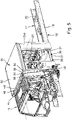
- the cabin module 24 is designed separately from the driver's cabin 13 and is prefabricated by individual elements, as in figure 9 shown to be assembled. The prefabricated cabin module 24 is then connected to the driver's cabin 13 in a manner that will be explained in more detail below.
- the cabin module 24 consists of various individual assemblies that are assembled to form the complete cabin module 24 .
- Two opposite side parts 25a, 25b are provided, each having door cutouts 26 and window cutouts 27.
- the side parts 25a, 25b are preferably made as sheet metal profiles, in particular aluminum sheet metal profiles.
- a door 28 is used, which is expediently also designed as an aluminum profile.
- a window 29 is inserted into each of the window cutouts 27 .
- a floor assembly 30 is also provided, which is expediently designed as a steel profile.
- the underbody 30 has a plate-like base element 31, on the underside of which there is a connection to the chassis 12 in a manner which will be described in more detail below.
- Attached to the floor element 31 on the upper side are two opposite seating group consoles 32a, 32b, between which a corridor 33 extends between the two side parts 25a, 25b.
- Seats (not shown) can be mounted on each of the seating group modules 32 .
- a rear wall 34 and a ceiling element 35 are also provided, which are expediently made of composite material, in particular designed as a GRP sandwich.
- the cabin module 24 is connected to the chassis 12 via a connection device 36 .
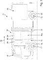
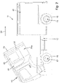
- the connecting device 36 is located on the underside of the floor assembly 30 and has a lock 37, via which the driver's cab 13 and the cab module 24 connected to it can be released together from the chassis 12 and folded up, as shown in figure 2 is shown. This allows access to the parts of the vehicle located in the chassis 12, in particular to engine and transmission parts.
- the lock 37 has legs 38a, 38b which project downwards on the underside of the floor pan 30 and which receive a locking element 39 between them.
- the locking element 39 interacts with a bearing 40 that is arranged on one of the two longitudinal beams 19 of the chassis 12, in particular welded there.
- the bearing 40 has two bearing legs 41a, 41b running parallel to one another, between which the locking element 39 dips.
- the locking element 39 is held on the bearing 40 with a locking bolt (not shown). This arrangement is also located in an identical manner on the other of the two longitudinal members 19 of the chassis 12 and assigned to it on the floor assembly 30.
- a damping device 42 acts between the cabin module 24 and the chassis 12, which is shown by way of example in the form of a fluid damper 43, in particular a hydraulic damper.
- the fluid damper 43 is mounted on the underside of the floor pan 30 .
- the adhesive connection is realized by means of a fastening device 44, ie driver's cabin 13 and cabin module 24 are not directly bonded to one another, which would also be possible, but with the interposition of the fastening device 44.
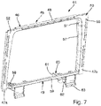
- the fastening device 44 has a frame-like fastening flange 45 .
- the frame-like fastening flange 45 is designed as an adapter and offers the possibility that the prefabricated cabin module 24 can be connected to driver's cabins 13 from different truck manufacturers.
- the frame-like fastening flange 45 is designed as a metal profile part, in particular as a steel profile part.
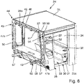
- the fastening flange 45 has a portal segment 46, which in turn has two side beams 47a, 47b extending in a vehicle height direction and a transverse beam 48 connecting the two side beams 47a, 47b to one another. Furthermore, the fastening flange 45 has a foot segment 49 at the lower end of the portal segment 46, which connects the two side rails 47a, 47b to one another.
- the portal segment 46 has a plurality of differently aligned attachment sections 50, 51, each having joining surfaces 52, 53, the latter being assigned to the cabin-side joining surfaces 54, 55 formed on the driver's cabin 13 or on the cabin module 24.
- the portal segment 46 also has a second fastening section 51, which has a second joining surface 53, the normal vector of which, however, is aligned essentially transversely to the longitudinal direction 20 of the vehicle.
- the second fastening section and thus the second joining surface 53 is located on the outside of a connecting piece 57 protruding from the first fastening section in the longitudinal direction 20 of the vehicle.
- fastening flange 45 and the driver's cabin 12 and/or the fastening flange 45 and the cabin module 24 have a plurality of mutually opposite joining surfaces 52, 53, 54, 55, which are at least partially embodied as adhesive surfaces glued to one another.
- the adhesive connection is formed between the fastening flange 45 and the driver's cabin 13, while the fastening flange is screwed onto the cabin module 24 on the other hand.
- the second joining surface 53 on the second fastening section 51 i.e. the outside of the connection piece 57 and the assigned second joining surface, form adhesive surfaces 58 glued to one another in the area of the rear wall of the driver's cabin 13.
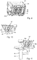
- the foot segment 49 of the fastening flange 45 has a base section 59 connecting the two side members 47a, 47b of the portal segment 46 to one another and at least one profile support 60 aligned perpendicular to the base section 59 and parallel to the longitudinal direction 20 of the vehicle.
- the pipe sockets are located on the underside of the base section 59 and are particularly welded there.
- the pipe sockets have a first end 61, which is expediently open, and a second end 62, on which, as in particular in figure 7 shown, a mounting plate 63 is mounted on the floor assembly 30 of the cabin module 24, in particular screwed there.
- the pipe sockets in particular the open first ends 61 thereof, interact with a fastening profile (not shown) on the driver's cabin 13, in particular in such a way that the first ends 61 of the pipe sockets also fit into the square tubes trained fastening profiles are inserted.
- the chassis 12 with the driver's cab 13 of a truck manufacturer is first provided according to customer requirements.
- the rear wall of the driver's cabin 13 is removed, in particular cut out.
- the cabin module 24 is prefabricated by assembling the individual assemblies, i.e. the floor assembly 30, the side parts 25a, 25b, the rear wall 34 and the ceiling element 35, with the windows and doors 28, 29 being inserted to form the cabin module in the form of a crew compartment module.
- the prefabricated cabin module has no wall opposite the rear wall of the driver's cabin, but is open at the front.
- either the fastening flange 45 is glued to the open rear wall of the driver's cabin 13 or the fastening flange is first screwed to the open front wall of the cabin module 24 . Then either the cabin module is glued to the driver's cabin 13 with the fastening flange 45 screwed on, or the cabin module 24 without a fastening flange 45, which is already glued to the driver's cabin 13, is screwed to the fastening flange 45.
Landscapes
- Engineering & Computer Science (AREA)
- Chemical & Material Sciences (AREA)
- Combustion & Propulsion (AREA)
- Transportation (AREA)
- Mechanical Engineering (AREA)
- Body Structure For Vehicles (AREA)
- Lighting Device Outwards From Vehicle And Optical Signal (AREA)
- Vehicle Body Suspensions (AREA)
- Control Of Motors That Do Not Use Commutators (AREA)
- Control Of Eletrric Generators (AREA)
Claims (11)
- Véhicule d'intérêt général, en particulier véhicule de sapeurs-pompiers, avec une cabine de conducteur (13) et un module de cabine (24) disposé derrière celle-ci dans la direction longitudinale de véhicule (20), relié à la cabine de conducteur (13), dans lequel pour la liaison de la cabine de conducteur (13) et du module de cabine (24) au moins une liaison adhésive est présente, et dans lequel pour la liaison de la cabine de conducteur (13) et du module de cabine (24) un dispositif de fixation (44) est présent et la au moins une liaison adhésive est réalisée entre le dispositif de fixation (44) et la cabine de conducteur (13) et/ou le dispositif de fixation (44) et le module de cabine (24), dans lequel le dispositif de fixation (44) est réalisé en tant que composant séparé aussi bien par rapport à la cabine de conducteur (13) que par rapport au module de cabine (24), et dans lequel le dispositif de fixation (44) présente une bride de fixation (45) du type cadre, qui est reliée d'une part à la cabine de conducteur (13) et d'autre part au module de cabine (24), dans lequel la au moins une liaison adhésive est réalisée entre la cabine de conducteur (13) et la bride de fixation (45) et/ou le module de cabine (24) et la bride de fixation (45), caractérisé en ce que la bride de fixation (45) et la cabine de conducteur (13) et/ou la bride de fixation (45) et le module de cabine (24) présentent plusieurs surfaces d'assemblage (52, 53, 54, 55) opposées les unes aux autres, qui sont réalisées au moins en partie en tant que surfaces adhésives (58) collées les unes aux autres.
- Véhicule d'intérêt général selon la revendication 1, caractérisé en ce qu'en plus d'au moins une liaison adhésive au moins une liaison par coopération de formes, en particulier liaison vissée et/ou rivetée est prévue.
- Véhicule d'intérêt général selon la revendication 1 ou 2, caractérisé en ce que la bride de fixation (45) présente un segment de portique (46) disposé entre une paroi arrière de la cabine de conducteur (13) et le module de cabine (24), sur lequel des surfaces adhésives côté bride sont réalisées, et un segment de pied (49) réalisé sur l'extrémité inférieure du segment de portique (46), dans lequel de préférence des surfaces adhésives côté bride sont également réalisées sur le segment de pied (49).
- Véhicule d'intérêt général selon la revendication 3, caractérisé en ce que la paroi arrière de la cabine de conducteur (13) et une face avant du module de cabine (24) présentent des ouvertures associées les unes aux autres, permettant en particulier un passage, qui sont raccordées les unes aux autres par l'intermédiaire du segment de portique (46) de la bride de fixation (45).
- Véhicule d'intérêt général selon la revendication 3 ou 4, caractérisé en ce que le segment de portique (46) présente deux traverses latérales (47a, 47b) s'étendant dans une direction en hauteur de véhicule et une traverse transversale (48) reliant les deux traverses latérales (47a, 47b) l'une à l'autre.
- Véhicule d'intérêt général selon l'une quelconque des revendications 3 à 5, caractérisé en ce que le segment de portique (46) présente une première partie de fixation (50), qui présente une première surface d'assemblage (52), dont le vecteur normal est orienté sensiblement parallèlement à la direction longitudinale de véhicule (20) et possède une deuxième partie de fixation (51), qui présente une deuxième surface d'assemblage (53), dont le vecteur normal est orienté sensiblement transversalement à la direction longitudinale de véhicule (20), dans lequel des surfaces d'assemblage (52), (53) côté cabine respectivement réalisées sur la cabine de conducteur (13) ou sur le module de cabine (24) sont associées à la première et deuxième surface d'assemblage (52), (53).
- Véhicule d'intérêt général selon la revendication 6, caractérisé en ce que les première et deuxième parties de fixation (50, 51) sont réalisées aussi bien sur les traverses latérales (47a, 47b) que sur la traverse transversale (48).
- Véhicule d'intérêt général selon la revendication 6 ou 7, caractérisé en ce que la première surface d'assemblage (52) et la surface d'assemblage (54) côté cabine associée sont reliées l'une à l'autre au moyen d'une liaison par coopération de formes et une deuxième surface d'assemblage (52) et la surface d'assemblage (55) côté cabine associée sont réalisées au moins en partie en tant que surfaces adhésives (58) collées les unes avec les autres.
- Véhicule d'intérêt général selon la revendication 8, caractérisé en ce qu'une surface d'assemblage (54) sur le module de cabine (24) est associée à la première surface d'assemblage (52) et une surface d'assemblage (55) sur la cabine de conducteur (13) à la deuxième surface d'assemblage (53).
- Véhicule d'intérêt général selon l'une quelconque des revendications 3 à 9, caractérisé en ce que le segment de pied (49) présente une partie de base (59) reliant les deux traverses latérales (47a, 47b) du segment de portique (46) l'une à l'autre et au moins un support de profilé (60) orienté perpendiculairement à la partie de base (59) et parallèlement à la direction longitudinale de véhicule (20), qui est relié à un profilé de fixation associé sur la cabine de conducteur (13) ou sur le module de cabine (24).
- Véhicule d'intérêt général selon la revendication 10, caractérisé en ce que des surfaces d'assemblage opposées les unes aux autres sont réalisées sur le support de profilé (60) et sur le profilé de fixation, qui sont réalisées au moins en partie sous la forme de surfaces d'assemblage (58) collées les unes avec les autres.
Priority Applications (1)
| Application Number | Priority Date | Filing Date | Title |
|---|---|---|---|
| HRP20221267TT HRP20221267T1 (hr) | 2017-04-03 | 2018-03-29 | Interventno vozilo |
Applications Claiming Priority (2)
| Application Number | Priority Date | Filing Date | Title |
|---|---|---|---|
| DE102017205601.0A DE102017205601A1 (de) | 2017-04-03 | 2017-04-03 | Einsatzfahrzeug |
| PCT/EP2018/058162 WO2018185003A1 (fr) | 2017-04-03 | 2018-03-29 | Véhicule d'intervention |
Publications (2)
| Publication Number | Publication Date |
|---|---|
| EP3558796A1 EP3558796A1 (fr) | 2019-10-30 |
| EP3558796B1 true EP3558796B1 (fr) | 2022-08-10 |
Family
ID=61913147
Family Applications (1)
| Application Number | Title | Priority Date | Filing Date |
|---|---|---|---|
| EP18716560.0A Active EP3558796B1 (fr) | 2017-04-03 | 2018-03-29 | Véhicule d'intervention |
Country Status (6)
| Country | Link |
|---|---|
| EP (1) | EP3558796B1 (fr) |
| DE (1) | DE102017205601A1 (fr) |
| ES (1) | ES2929247T3 (fr) |
| HR (1) | HRP20221267T1 (fr) |
| PL (1) | PL3558796T3 (fr) |
| WO (1) | WO2018185003A1 (fr) |
Families Citing this family (1)
| Publication number | Priority date | Publication date | Assignee | Title |
|---|---|---|---|---|
| US12077233B1 (en) * | 2023-06-21 | 2024-09-03 | Ford Global Technologies, Llc | Method of assembling a truck |
Family Cites Families (9)
| Publication number | Priority date | Publication date | Assignee | Title |
|---|---|---|---|---|
| US5560673A (en) * | 1994-02-04 | 1996-10-01 | Paccar Inc. | Truck cab and sleeper assembly |
| NL9400891A (nl) * | 1994-06-01 | 1996-01-02 | Plastisol Nv | Motorvoertuig. |
| US6276748B1 (en) * | 1998-03-17 | 2001-08-21 | Western Sear Trucks Inc. | Lightweight cab/sleeper for trucks |
| DE10101362A1 (de) * | 2001-01-13 | 2002-07-18 | Siemens Duewag Gmbh | Großräumiges Fahrzeug, insbesondere Schienenfahrzeug |
| AT413205B (de) | 2001-12-13 | 2005-12-15 | Rosenbauer Int Ag | Feuerwehrfahrzeug |
| US6557230B1 (en) * | 2001-12-21 | 2003-05-06 | Dan H. Gernstein | Method of converting a truck sleeper cab to a day cab |
| US6719361B1 (en) * | 2002-10-29 | 2004-04-13 | Mack Trucks, Inc. | Truck sleeper cab to day cab conversion kit assembly |
| US6935679B2 (en) * | 2003-09-03 | 2005-08-30 | Mack Trucks, Inc. | Modular cab, sleeper and roof structural assembly for a truck-tractor vehicle |
| DE202010016192U1 (de) | 2010-12-06 | 2011-03-17 | Albert Ziegler Gmbh & Co. Kg | Einsatzfahrzeug, insbesondere Feuerwehrfahrzeug |
-
2017
- 2017-04-03 DE DE102017205601.0A patent/DE102017205601A1/de not_active Ceased
-
2018
- 2018-03-29 PL PL18716560.0T patent/PL3558796T3/pl unknown
- 2018-03-29 EP EP18716560.0A patent/EP3558796B1/fr active Active
- 2018-03-29 HR HRP20221267TT patent/HRP20221267T1/hr unknown
- 2018-03-29 WO PCT/EP2018/058162 patent/WO2018185003A1/fr unknown
- 2018-03-29 ES ES18716560T patent/ES2929247T3/es active Active
Also Published As
| Publication number | Publication date |
|---|---|
| PL3558796T3 (pl) | 2022-12-19 |
| HRP20221267T1 (hr) | 2022-12-09 |
| ES2929247T3 (es) | 2022-11-25 |
| WO2018185003A1 (fr) | 2018-10-11 |
| DE102017205601A1 (de) | 2018-10-04 |
| EP3558796A1 (fr) | 2019-10-30 |
Similar Documents
| Publication | Publication Date | Title |
|---|---|---|
| DE10219275B4 (de) | Fahrgestell für ein Nutzfahrzeug | |
| DE102006009189B3 (de) | Befestigungsanordnung von Außenanbauteilen an einem Tragrahmen eines Lastkraftwagens | |
| WO2016120061A1 (fr) | Bloc porte-module pour un véhicule automobile | |
| DE19708215A1 (de) | Schweller eines Kraftfahrzeugs mit einer Verstärkungseinlage | |
| DE102015215655A1 (de) | Fahrzeugkarosserie | |
| DE102009050495A1 (de) | Hilfsrahmen | |
| DE102005038463A1 (de) | Träger einer Kraftwagenkarosserie | |
| DE102019211103A1 (de) | Karosseriestruktur für ein elektrisch betriebenes Fahrzeug | |
| DE29800368U1 (de) | Geschraubter Hilfsrahmen | |
| EP3239022B1 (fr) | Composite de plateforme | |
| DE102009035405A1 (de) | Verfahren zum Zusammenbauen des Rahmens eines Fahrzeugvordersitzes | |
| DE102005050951B4 (de) | Fronttragstruktur für ein Kraftfahrzeug | |
| EP2559609B1 (fr) | Cadre de renfort et procédé de mise en place d'un cadre de renfort dans une carrosserie de véhicule | |
| EP3558796B1 (fr) | Véhicule d'intervention | |
| DE102020129513A1 (de) | Bausatzsysteme zur teilweisen oder vollständigen Montage eines Nutzfahrzeuges | |
| DE4333314C2 (de) | Rahmen für Nutzfahrzeuge | |
| DE10045063B4 (de) | Fahrgestell mit einer Chassis-Baugruppe mit Federböcken für Straßenfahrzeuge | |
| EP3348455B1 (fr) | Structure de support pour un véhicule utilitaire non entraîné | |
| EP2700554B1 (fr) | Dispositif de fixation en porte-à-faux d'un siège passager et procédé de fabrication d'un tel dispositif ainsi que caisse de voiture | |
| DE102012013903B4 (de) | Rahmentragstruktur mit nach seitlich außen gekröpften Tragabschnitten | |
| DE102016211717B4 (de) | Karosseriestruktur für ein Nutzfahrzeug | |
| EP0779202B1 (fr) | Véhicule d'intervention | |
| AT400325B (de) | Kraftfahrzeugkörper | |
| DE102015220308B3 (de) | Karosseriestruktur für ein zweispuriges Fahrzeug | |
| DE10140921A1 (de) | Fahrgestell für ein Nutzfahrzeug, Bausatz und Verfahren zur Spurverbreiterung und Radstandsverlängerung des Fahrgestells |
Legal Events
| Date | Code | Title | Description |
|---|---|---|---|
| STAA | Information on the status of an ep patent application or granted ep patent |
Free format text: STATUS: UNKNOWN |
|
| STAA | Information on the status of an ep patent application or granted ep patent |
Free format text: STATUS: THE INTERNATIONAL PUBLICATION HAS BEEN MADE |
|
| PUAI | Public reference made under article 153(3) epc to a published international application that has entered the european phase |
Free format text: ORIGINAL CODE: 0009012 |
|
| STAA | Information on the status of an ep patent application or granted ep patent |
Free format text: STATUS: REQUEST FOR EXAMINATION WAS MADE |
|
| 17P | Request for examination filed |
Effective date: 20190627 |
|
| AK | Designated contracting states |
Kind code of ref document: A1 Designated state(s): AL AT BE BG CH CY CZ DE DK EE ES FI FR GB GR HR HU IE IS IT LI LT LU LV MC MK MT NL NO PL PT RO RS SE SI SK SM TR |
|
| AX | Request for extension of the european patent |
Extension state: BA ME |
|
| STAA | Information on the status of an ep patent application or granted ep patent |
Free format text: STATUS: EXAMINATION IS IN PROGRESS |
|
| DAV | Request for validation of the european patent (deleted) | ||
| DAX | Request for extension of the european patent (deleted) | ||
| 17Q | First examination report despatched |
Effective date: 20200616 |
|
| STAA | Information on the status of an ep patent application or granted ep patent |
Free format text: STATUS: EXAMINATION IS IN PROGRESS |
|
| GRAP | Despatch of communication of intention to grant a patent |
Free format text: ORIGINAL CODE: EPIDOSNIGR1 |
|
| STAA | Information on the status of an ep patent application or granted ep patent |
Free format text: STATUS: GRANT OF PATENT IS INTENDED |
|
| INTG | Intention to grant announced |
Effective date: 20220401 |
|
| GRAS | Grant fee paid |
Free format text: ORIGINAL CODE: EPIDOSNIGR3 |
|
| GRAA | (expected) grant |
Free format text: ORIGINAL CODE: 0009210 |
|
| STAA | Information on the status of an ep patent application or granted ep patent |
Free format text: STATUS: THE PATENT HAS BEEN GRANTED |
|
| AK | Designated contracting states |
Kind code of ref document: B1 Designated state(s): AL AT BE BG CH CY CZ DE DK EE ES FI FR GB GR HR HU IE IS IT LI LT LU LV MC MK MT NL NO PL PT RO RS SE SI SK SM TR |
|
| REG | Reference to a national code |
Ref country code: AT Ref legal event code: REF Ref document number: 1510354 Country of ref document: AT Kind code of ref document: T Effective date: 20220815 Ref country code: CH Ref legal event code: EP |
|
| REG | Reference to a national code |
Ref country code: DE Ref legal event code: R096 Ref document number: 502018010351 Country of ref document: DE |
|
| REG | Reference to a national code |
Ref country code: IE Ref legal event code: FG4D Free format text: LANGUAGE OF EP DOCUMENT: GERMAN |
|
| REG | Reference to a national code |
Ref country code: FI Ref legal event code: FGE |
|
| REG | Reference to a national code |
Ref country code: SE Ref legal event code: TRGR |
|
| REG | Reference to a national code |
Ref country code: NL Ref legal event code: FP |
|
| REG | Reference to a national code |
Ref country code: ES Ref legal event code: FG2A Ref document number: 2929247 Country of ref document: ES Kind code of ref document: T3 Effective date: 20221125 |
|
| REG | Reference to a national code |
Ref country code: NO Ref legal event code: T2 Effective date: 20220810 |
|
| REG | Reference to a national code |
Ref country code: HR Ref legal event code: T1PR Ref document number: P20221267 Country of ref document: HR |
|
| REG | Reference to a national code |
Ref country code: LT Ref legal event code: MG9D |
|
| REG | Reference to a national code |
Ref country code: GR Ref legal event code: EP Ref document number: 20220402187 Country of ref document: GR Effective date: 20221212 |
|
| PG25 | Lapsed in a contracting state [announced via postgrant information from national office to epo] |
Ref country code: RS Free format text: LAPSE BECAUSE OF FAILURE TO SUBMIT A TRANSLATION OF THE DESCRIPTION OR TO PAY THE FEE WITHIN THE PRESCRIBED TIME-LIMIT Effective date: 20220810 Ref country code: PT Free format text: LAPSE BECAUSE OF FAILURE TO SUBMIT A TRANSLATION OF THE DESCRIPTION OR TO PAY THE FEE WITHIN THE PRESCRIBED TIME-LIMIT Effective date: 20221212 Ref country code: LV Free format text: LAPSE BECAUSE OF FAILURE TO SUBMIT A TRANSLATION OF THE DESCRIPTION OR TO PAY THE FEE WITHIN THE PRESCRIBED TIME-LIMIT Effective date: 20220810 Ref country code: LT Free format text: LAPSE BECAUSE OF FAILURE TO SUBMIT A TRANSLATION OF THE DESCRIPTION OR TO PAY THE FEE WITHIN THE PRESCRIBED TIME-LIMIT Effective date: 20220810 |
|
| PG25 | Lapsed in a contracting state [announced via postgrant information from national office to epo] |
Ref country code: IS Free format text: LAPSE BECAUSE OF FAILURE TO SUBMIT A TRANSLATION OF THE DESCRIPTION OR TO PAY THE FEE WITHIN THE PRESCRIBED TIME-LIMIT Effective date: 20221210 |
|
| REG | Reference to a national code |
Ref country code: HR Ref legal event code: ODRP Ref document number: P20221267 Country of ref document: HR Payment date: 20230317 Year of fee payment: 6 |
|
| PG25 | Lapsed in a contracting state [announced via postgrant information from national office to epo] |
Ref country code: SM Free format text: LAPSE BECAUSE OF FAILURE TO SUBMIT A TRANSLATION OF THE DESCRIPTION OR TO PAY THE FEE WITHIN THE PRESCRIBED TIME-LIMIT Effective date: 20220810 Ref country code: RO Free format text: LAPSE BECAUSE OF FAILURE TO SUBMIT A TRANSLATION OF THE DESCRIPTION OR TO PAY THE FEE WITHIN THE PRESCRIBED TIME-LIMIT Effective date: 20220810 Ref country code: DK Free format text: LAPSE BECAUSE OF FAILURE TO SUBMIT A TRANSLATION OF THE DESCRIPTION OR TO PAY THE FEE WITHIN THE PRESCRIBED TIME-LIMIT Effective date: 20220810 |
|
| REG | Reference to a national code |
Ref country code: DE Ref legal event code: R097 Ref document number: 502018010351 Country of ref document: DE |
|
| PG25 | Lapsed in a contracting state [announced via postgrant information from national office to epo] |
Ref country code: SK Free format text: LAPSE BECAUSE OF FAILURE TO SUBMIT A TRANSLATION OF THE DESCRIPTION OR TO PAY THE FEE WITHIN THE PRESCRIBED TIME-LIMIT Effective date: 20220810 Ref country code: EE Free format text: LAPSE BECAUSE OF FAILURE TO SUBMIT A TRANSLATION OF THE DESCRIPTION OR TO PAY THE FEE WITHIN THE PRESCRIBED TIME-LIMIT Effective date: 20220810 |
|
| PLBE | No opposition filed within time limit |
Free format text: ORIGINAL CODE: 0009261 |
|
| STAA | Information on the status of an ep patent application or granted ep patent |
Free format text: STATUS: NO OPPOSITION FILED WITHIN TIME LIMIT |
|
| P01 | Opt-out of the competence of the unified patent court (upc) registered |
Effective date: 20230519 |
|
| PG25 | Lapsed in a contracting state [announced via postgrant information from national office to epo] |
Ref country code: AL Free format text: LAPSE BECAUSE OF FAILURE TO SUBMIT A TRANSLATION OF THE DESCRIPTION OR TO PAY THE FEE WITHIN THE PRESCRIBED TIME-LIMIT Effective date: 20220810 |
|
| 26N | No opposition filed |
Effective date: 20230511 |
|
| PG25 | Lapsed in a contracting state [announced via postgrant information from national office to epo] |
Ref country code: SI Free format text: LAPSE BECAUSE OF FAILURE TO SUBMIT A TRANSLATION OF THE DESCRIPTION OR TO PAY THE FEE WITHIN THE PRESCRIBED TIME-LIMIT Effective date: 20220810 |
|
| PG25 | Lapsed in a contracting state [announced via postgrant information from national office to epo] |
Ref country code: MC Free format text: LAPSE BECAUSE OF FAILURE TO SUBMIT A TRANSLATION OF THE DESCRIPTION OR TO PAY THE FEE WITHIN THE PRESCRIBED TIME-LIMIT Effective date: 20220810 |
|
| REG | Reference to a national code |
Ref country code: IE Ref legal event code: MM4A |
|
| PG25 | Lapsed in a contracting state [announced via postgrant information from national office to epo] |
Ref country code: IE Free format text: LAPSE BECAUSE OF NON-PAYMENT OF DUE FEES Effective date: 20230329 |
|
| PGFP | Annual fee paid to national office [announced via postgrant information from national office to epo] |
Ref country code: GR Payment date: 20240319 Year of fee payment: 7 |
|
| REG | Reference to a national code |
Ref country code: HR Ref legal event code: ODRP Ref document number: P20221267 Country of ref document: HR Payment date: 20240320 Year of fee payment: 7 |
|
| PGFP | Annual fee paid to national office [announced via postgrant information from national office to epo] |
Ref country code: NL Payment date: 20240320 Year of fee payment: 7 Ref country code: LU Payment date: 20240321 Year of fee payment: 7 |
|
| PGFP | Annual fee paid to national office [announced via postgrant information from national office to epo] |
Ref country code: AT Payment date: 20240318 Year of fee payment: 7 |
|
| PGFP | Annual fee paid to national office [announced via postgrant information from national office to epo] |
Ref country code: FI Payment date: 20240319 Year of fee payment: 7 Ref country code: DE Payment date: 20240119 Year of fee payment: 7 Ref country code: CZ Payment date: 20240318 Year of fee payment: 7 Ref country code: GB Payment date: 20240322 Year of fee payment: 7 |
|
| PGFP | Annual fee paid to national office [announced via postgrant information from national office to epo] |
Ref country code: TR Payment date: 20240318 Year of fee payment: 7 Ref country code: SE Payment date: 20240321 Year of fee payment: 7 Ref country code: PL Payment date: 20240219 Year of fee payment: 7 Ref country code: NO Payment date: 20240227 Year of fee payment: 7 Ref country code: IT Payment date: 20240329 Year of fee payment: 7 Ref country code: HR Payment date: 20240320 Year of fee payment: 7 Ref country code: FR Payment date: 20240320 Year of fee payment: 7 Ref country code: BE Payment date: 20240320 Year of fee payment: 7 |
|
| PGFP | Annual fee paid to national office [announced via postgrant information from national office to epo] |
Ref country code: CH Payment date: 20240401 Year of fee payment: 7 |
|
| PGFP | Annual fee paid to national office [announced via postgrant information from national office to epo] |
Ref country code: ES Payment date: 20240417 Year of fee payment: 7 |