EP3558782B1 - Fahrzeug mit einer türschwelle - Google Patents
Fahrzeug mit einer türschwelle Download PDFInfo
- Publication number
- EP3558782B1 EP3558782B1 EP17832763.1A EP17832763A EP3558782B1 EP 3558782 B1 EP3558782 B1 EP 3558782B1 EP 17832763 A EP17832763 A EP 17832763A EP 3558782 B1 EP3558782 B1 EP 3558782B1
- Authority
- EP
- European Patent Office
- Prior art keywords
- door sill
- vehicle
- plate
- carriage body
- tread plate
- Prior art date
- Legal status (The legal status is an assumption and is not a legal conclusion. Google has not performed a legal analysis and makes no representation as to the accuracy of the status listed.)
- Active
Links
Images



Classifications
-
- B—PERFORMING OPERATIONS; TRANSPORTING
- B61—RAILWAYS
- B61D—BODY DETAILS OR KINDS OF RAILWAY VEHICLES
- B61D19/00—Door arrangements specially adapted for rail vehicles
- B61D19/02—Door arrangements specially adapted for rail vehicles for carriages
-
- B—PERFORMING OPERATIONS; TRANSPORTING
- B61—RAILWAYS
- B61D—BODY DETAILS OR KINDS OF RAILWAY VEHICLES
- B61D17/00—Construction details of vehicle bodies
- B61D17/04—Construction details of vehicle bodies with bodies of metal; with composite, e.g. metal and wood body structures
- B61D17/10—Floors
-
- B—PERFORMING OPERATIONS; TRANSPORTING
- B61—RAILWAYS
- B61D—BODY DETAILS OR KINDS OF RAILWAY VEHICLES
- B61D23/00—Construction of steps for railway vehicles
Definitions
- the invention relates to a vehicle body with a door sill, in particular for a rail vehicle body.
- the door sill of a passenger rail vehicle is a highly stressed component which, in addition to strong mechanical loads, is also exposed to changing environmental influences.
- the door sill is exposed to greater amounts of water, snow and ice than the rest of the passenger compartment floor.
- the door sill represents the lateral closure of the passenger compartment floor to the area surrounding the vehicle and is generally made of metal. It is usually attached to the underframe by means of a screw connection, with the screws being fed in and tightened from the passenger compartment side. This requires reliable sealing of the screw holes against moisture penetration over long periods of time. If this seal fails, moisture can penetrate areas of the underframe from which it can no longer drain and lead to excessive corrosion there.
- the position of the door sill is determined by the attachment means on the car body, for example bores or threads, and is therefore subject to manufacturing tolerances.
- An exact adjustment of the Door sill is only possible to a limited extent, for example by inserting spacers to achieve an optimal installation height that matches the vehicle floor.
- Door sills are known from the prior art, as the Japanese patent application shows JP 2007 176429 A a door sill with a detachable step plate. However, this footplate cannot be adjusted in its position relative to the car body.
- Another solution is in the European patent specification EP 2 132 078 B1 disclosed wherein shims are used to adjust the vertical distance between a door sill and the lower door track. In Scripture JP2005145344A a similar construction is shown.
- the invention is therefore based on the object of specifying a door sill for a vehicle which can be adjusted in all three spatial directions during assembly and which does not allow any moisture to penetrate into the structure of the vehicle.
- a car body of a vehicle with a door sill comprising a step plate and fastening means for detachable fastening to the car body, a labyrinth plate being inserted between the car body and the step plate, which labyrinth plate has bores for the passage of the fastening means. These bores having a diameter such that the tread plate can be displaced horizontally with respect to the car body, and the vertical position of the tread plate with respect to the car body can be adjusted by inserting spacer discs.
- the advantage can be achieved of being able to adjust a door sill in all three spatial directions during installation in such a way that there is an optimal connection to the surrounding components.
- positional tolerances of fastening means on the car body can be compensated for and the height of the door sill can be adjusted in relation to the floor.
- the door sill includes a step plate, which forms the end of a passenger compartment floor in the area of an entrance.
- This step plate is made of metal, for example by means of an extrusion process, and protects the edge of a passenger compartment floor.
- the footplate is fastened by means of fastening means which allow the connection point to be detached, preferably a screw connection.
- fastening means on the car body for example threads, are to be provided, the position of which is subject to tolerances in relation to the car body.
- the tread plate also includes a contact point to a vehicle floor, which is to be sealed in particular against the ingress of moisture into the door sill, the car body and the area below the vehicle floor. Since such a contact point cannot in practice be sealed over the entire service life of a vehicle, The present invention offers a solution for allowing moisture that has penetrated there to drain out of this room.
- the height of a passenger compartment floor in relation to the car body is subject to such tolerances that the door sill must include a means of adjusting its height.
- the door sill is made up of a tread plate which can be detachably fastened to a car body.
- a labyrinth plate is inserted between the footplate and the car body, which includes channels between an outside and an inside, each of which has at least two changes of direction by 90 degrees.
- a fluid typically water
- the labyrinthine structure of the channels reduces the entry of moisture from the outside through these channels, for example when driving in the rain.
- the labyrinth plate is equipped with passages (holes, recesses) which allow fastening means, typically screws, to be pushed through.
- the dimensions of these bores are to be selected in such a way that the stepping plate can be displaced to the required extent. From the desired displacement of the footplate in relation to the car body and the permissible positional tolerances arranged on the car body fasteners is a measure of the diameter of the To determine bores, so that even if the position tolerances of the fasteners are fully utilized, the specified adjustment range (displaceability) of the step plate is given.
Landscapes
- Engineering & Computer Science (AREA)
- Mechanical Engineering (AREA)
- Life Sciences & Earth Sciences (AREA)
- Wood Science & Technology (AREA)
- Body Structure For Vehicles (AREA)
Description
- Wagenkasten eines Fahrzeugs mit einer Türschwelle.
- Die Erfindung betrifft einen Wagenkasten eines Fahrzeugs mit einer Türschwelle, insbesondere für einen Schienenfahrzeugwagenkasten.
- Die Türschwelle eines Passagierschienenfahrzeugs ist ein hochbelastetes Bauteil, welches neben starken mechanischen Belastungen auch wechselnden Umwelteinflüssen ausgesetzt ist. Insbesondere ist die Türschwelle größeren Wasser- Schnee- und Eismengen ausgesetzt ist als der weitere Passagierraumboden. Die Türschwelle stellt den seitlichen Abschluß des Passagierraumbodens zur Umgebung des Fahrzeugs dar und wird im Allgemeinen aus Metall gefertigt. Die Befestigung erfolgt meist mittels Schraubverbindung an dem Untergestell, wobei die Schrauben von der Passagierraumseite zugeführt und angezogen werden. Dies erfordert eine zuverlässige Dichtung der Schraubenlöcher gegen eindringende Feuchtigkeit über lange Zeiträume. Versagt diese Dichtung, so kann Feuchtigkeit in Bereiche des Untergestells eindringen aus welchen es nicht mehr abfließen kann und dort zu übermäßiger Korrosion führen. Die Position der Türschwelle ist durch die wagenkastenseitigen Befestigungsmittel, beispielsweise Bohrungen oder Gewinde festgelegt und somit den Toleranzen der Herstellung unterworfen. Eine exakte Justierung der Türschwelle ist nur eingeschränkt möglich, etwa durch das Einlegen von Abstandsscheiben um eine optimale, zu dem Fahrzeugfußboden passende Einbauhöhe zu erzielen. Aus dem Stand der Technik sind Türschwellen bekannt, so zeigt die japanische Patentanmeldung
JP 2007 176429 A EP 2 132 078 B1 offenbart, wobei Abstandsscheiben zur Einstellung des vertikalen Abstandes zwischen einer Türschwelle und der unteren Türführung eingesetzt sind. In der SchriftJP2005145344A - Der Erfindung liegt daher die Aufgabe zugrunde, eine Türschwelle für ein Fahrzeug anzugeben, welche bei ihrer Montage in allen drei Raumrichtungen justierbar ist und welche keinen Feuchtigkeitseintritt in die Struktur des Fahrzeugs zulässt.
- Die Aufgabe wird durch einen Wagenkasten eines Fahrzeugs mit einer Türschwelle mit den Merkmalen des Anspruchs 1 gelöst. Vorteilhafte Ausgestaltungen sind Gegenstand untergeordneter Ansprüche.
- Dem Grundgedanken der Erfindung nach wird einen Wagenkasten eines Fahrzeugs mit einer Türschwelle, umfassend eine Trittplatte und Befestigungsmittel zur lösbaren Befestigung an dem Wagenkasten beschrieben, wobei zwischen dem Wagenkasten und der Trittplatte eine Labyrinthplatte eingelegt ist, welche Bohrungen zur Durchführung der Befestigungsmittel umfasst, wobei diese Bohrungen einen solchen Durchmesser aufweisen, der ein horizontales Verschieben der Trittplatte in Bezug auf den Wagenkasten erlaubt, und wobei die vertikale Position der Trittplatte in Bezug auf den Wagenkasten durch das Einlegen von Abstandsscheiben einstellbar ist.
- Dadurch ist der Vorteil erzielbar, eine Türschwelle während des Einbaus in allen drei Raumrichtungen so justieren zu können, dass ein optimaler Anschluß zu den umgebenden Bauteilen gegeben ist. Insbesondere können dadurch Lagetoleranzen von Wagenkastenseitigen Befestigungsmitteln ausgeglichen werden und die Höhenlage der Türschwelle in Bezug auf den Fußboden justiert werden.
- Die Türschwelle umfasst eine Trittplatte, welchen den Abschluß eines Passagierraumbodens im Bereich eines Einstiegs bildet. Diese Trittplatte ist aus Metall gefertigt, beispielsweise mittels eines Strangpreßverfahrens und schützt die Kante eines Passagierraumfußbodens.
- Die Befestigung der Trittplatte erfolgt mittels Befestigungsmitteln, welche eine Lösbarkeit der Verbindungsstelle erlauben, vorzugsweise eine Schraubverbindung. Dazu sind korrespondierende wagenkastenseitige Befestigungsmittel, beispielsweise Gewinde, vorzusehen, der Lage in Bezug auf den Wagenkasten Toleranzen unterworden ist.
- Die Trittplatte umfasst des Weiteren eine Kontaktstelle zu einem Fahrzeugfußboden, welche insbesondere gegen den Eintritt von Feuchtigkeit in die Türschwelle, den Wagenkasten und den Bereich unterhalb des Fahrzeugfußbodens abzudichten ist. Da eine solche Kontaktstelle in der Praxis nicht über die gesamte Lebensdauer eines Fahrzeugs abdichtbar ist, bietet gegenständliche Erfindung eine Lösung, um dort eingedrungene Feuchtigkeit wieder aus diesem Raum abfließen zu lassen.
- Die Höhenlage eines Passagierraumbodens in Bezug auf den Wagenkasten ist mit solchen Toleranzen behaftet, dass die Türschwelle eine Möglichkeit zur Justierung ihrer Höhenlage umfassen muß.
- Die Türschwelle ist aus einer Trittplatte aufgebaut, welche an einem Wagenkasten lösbar befestigbar ist. Dabei ist erfindungsgemäß zwischen der Trittplatte und dem Wagenkasten eine Labyrinthplatte eingelegt, welche Kanäle zwischen einer Außenseite und einer Innenseite umfassen, welche jeweils einen mindestens zweimaligen Richtungswechsel um 90 Grad aufweisen. Durch diese Kanäle kann ein Fluid, typischerweise Wasser, strömen. Solcherart ist eine Verbindung zwischen einer Außenseite der Türschwelle und einer in einen Hohlraum mündenden Innenseite geschaffen, aus welchem die durch eine fehlerhafte Dichtung zwischen der Trittplatte und dem Fahrzeugfußboden Feuchtigkeit abfließen kann. Die labyrinthartige Struktur der Kanäle reduziert den Feuchtigkeitseintrag von außen durch diese Kanäle, beispielsweise bei einer Regenfahrt.
- Die Labyrinthplatte ist mit Durchführungen (Bohrungen, Ausnehmungen) ausgestattet, welche ein Durchstecken von Befestigungsmitteln, typischerweise Schrauben zulassen. Dabei sind die Abmessungen dieser Bohrungen so zu wählen, dass ein Verschieben der Trittplatte in dem erforderlichen Ausmaß möglich ist. Aus der gewünschten Verschiebbarkeit der Trittplatte in Bezug auf den Wagenkasten und den zulässigen Lagetoleranzen der an dem Wagenkasten angeordneten Befestigungsmitteln ist ein Maß für den Durchmesser der Bohrungen zu bestimmen, sodass auch bei vollständigem Ausnutzen der Lagetoleranzen der Befestigungsmittel der vorgegebene Justierbereich (Verschiebbarkeit) der Trittplatte gegeben ist.
- Es zeigen beispielhaft:
- Fig.1
- Montage einer Türschwelle, Schritt 1.
- Fig.2
- Montage einer Türschwelle, Schritt 2.
- Fig.3
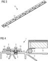
- Labyrinthplatte.
- Fig.4
- Montage einer Türschwelle, Schritt 3.
- Fig.5
- Montage einer Türschwelle, Schritt 4.
- Fig.6
- Montage einer Türschwelle, Schritt 5.
- Fig.7
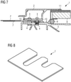
- Montage einer Türschwelle, Schritt 6.
- Fig.8
- Abstandsscheibe.
- Fig.9
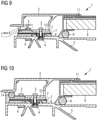
- Montage einer Türschwelle, Schritt 7.
- Fig.10
- Türschwelle, abgedichtet.
- Fig.11
- Türschwelle mit Entwässerung.
-
-
Fig.1 zeigt beispielhaft und schematisch den ersten Schritt eines Montagevorgangs einer Türschwelle. Es ist ein Schnitt quer zur Längsachse eines Fahrzeugs im Bereich eines Passagiereinstiegs dargestellt. Das Fahrzeug umfasst an der gezeigten Stelle einen Wagenkasten 5, welcher aus stranggepressten Leichtmetallprofilen aufgebaut ist und eine Fußbodenplatte 8. Die Fußbodenplatte 8 bildet den von den Passagieren betretbaren Boden und ist mit einer geeigneten Unterkonstruktion (inFig.1 nicht dargestellt) mit dem Wagenkasten verbunden. Zur Verhinderung des Feuchtigkeitseintritts in den Bereich unter der Fußbodenplatte 8 ist eine Dichtung 9 vorgesehen, welche in gezeigtem Ausführungsbeispiel als eingeklebte Dichtschnur ausgebildet ist. Neben der Fußbodenplatte 8, in Richtung der Außenseite des Fahrzeugs sind Befestigungsmittel angeordnet, welche beispielhaft als eingeschweißte Gewindeeinsätze 4 ausgebildet sind. Diese bieten im Gegensatz zu einfachen Durchgangsgewinden den Vorteil, dass Feuchtigkeit nicht durchdringen kann. -
Fig.2 zeigt beispielhaft und schematisch den zweiten Schritt eines Montagevorgangs einer Türschwelle. Es ist der Einbauort einer Türschwelle 1 ausFig.1 dargestellt, wobei eine Labyrinthplatte 6 in ihre Einbausituation eingelegt ist. Die Labyrinthplatte weist Bohrungen 13 auf, durch welche die Gewindeeinsätze 4 durchdringen können. Dabei sind die Bohrungen 13 so bemessen, dass sie sowohl die Lagetoleranzen der Gewindeeinsätze 4 als auch den erforderlichen Justierbereich einer Trittplatte (inFig.2 noch nicht dargestellt) sicherstellen. -
Fig.3 zeigt beispielhaft und schematisch Labyrinthplatte. Es ist eine Schrägansicht auf die Unterseite einer Labyrinthplatte 6 dargestellt. Die Innenseite und die Außenseite der Labyrinthplatte 6 sind mit Kanälen 12 verbunden, welche als Vertiefungen in der Labyrinthplatte 6 ausgebildet sind. Der Verlauf der Kanäle 12 ist labyrinthartig ausgebildet, sodass der unmittelbare Durchfluß eines Fluids (im Allgemeinen Wasser) behindert ist. Ein langsames Durchfließen ist jedoch möglich. Insbesondere wird dadurch das Eindringen großer Wassermengen von Außerhalb des Fahrzeugs verhindert, das Ausfließen geringer Mengen von innen nach außen jedoch nicht. -
Fig.4 zeigt beispielhaft und schematisch den dritten Schritt eines Montagevorgangs einer Türschwelle. In diesem dritten Schritt des Einbaus einer Türschwelle 1 sind Schrauben 3 in die Gewindeeinsätze 4 locker eingeschraubt, wobei je Schraube 3 eine Kraftverteilerplatte 10 beigelegt ist. -
Fig.5 zeigt beispielhaft und schematisch den vierten Schritt eines Montagevorgangs einer Türschwelle. In diesem vierten Schritt des Einbaus einer Türschwelle 1 wird eine Trittplatte 2 in ihre Einbaulage gebracht. Die Trittplatte 2 ist als stranggepresstes Leichtmetallprofil ausgeführt und weist eine in Richtung des Passagierraums orientierte Fläche mit einer rutschhemmenden Riffelung auf. Eine Ausformung der Trittplatte 2 in Richtung der Fußbodenplatte 8 ist so geformt, dass sie in eingebauter Position mit der Fußbodenplatte 8 überlappt. Entlang dieser Überlappung ist eine Fußbodendichtung 11 vorgesehen, welche in eine Ausnehmung an der Trittplatte eingebracht ist. Diese Fußbodendichtung 11 stellt eine Sperre gegen Feuchtigkeit dar und verhindert das Eindringen der Feuchtigkeit in Hohlräume unterhalb der Trittplatte 2. Die Trittplatte 2 ist so geformt, dass die Kraftverteilerplatten 10 in einen Hohlraum einführbar sind, wobei es besonders vorteilhaft ist, die Kraftverteilerplatten 10 mit einer angeschrägten Fläche (Fase) auszustatten, sodass die Montage wesentlich erleichtert wird. -
Fig.6 zeigt beispielhaft und schematisch den fünften Schritt eines Montagevorgangs einer Türschwelle. In diesem Einbauschritt ist die Trittplatte 2 in ihrer Einbaulage befindlich, jedoch ist weder ihre vertikale noch ihre laterale Position festgelegt. Insbesondere die vertikale Lage (Höhenposition) ist exakt auf die jeweilige Höhe der Fußbodenplatte abzustimmen, sodass die Fußbodendichtung 11 ihre Wirkung entfalten kann. -
Fig.7 zeigt beispielhaft und schematisch den sechsten Schritt eines Montagevorgangs einer Türschwelle. In diesem sechsten Schritt des Einbaus einer Türschwelle 1 wird die exakte Höhenlage der Trittplatte 2 justiert. Dazu werden Abstandsscheiben 7, 7' in den Spalt zwischen der Trittplatte 2 und der Labyrinthplatte 6 eingelegt. Die jeweils erforderliche Dicke dieser Abstandsscheiben ist bei der Montage zu ermitteln. InFig.7 ist beispielshaft der Fall gezeigt, bei welchem eine dickere Abstandsscheibe 7 und eine dünnere Abstandsscheibe 7' gemeinsam die erforderliche Höhenlage der Trittplatte 2 gewährleisten. -
Fig.8 zeigt beispielhaft und schematisch eine Abstandsscheibe. Es ist eine Abstandsscheibe 7 dargestellt, welche vorzugsweise aus Metall gefertigt ist und welche zwei Ausnehmungen aufweist in welche in eingebauter Position der Abstandsscheibe 7 die Schraubverbindungen 3 dringen. -
Fig.9 zeigt beispielhaft und schematisch den siebenten Schritt eines Montagevorgangs einer Türschwelle. In diesem siebenten Schritt ist die Trittplatte 2 in ihrer korrekten Höhenlage befindlich und kann nun in ihrer lateralen Position justiert werden. Ist die korrekte horizontale Position gegeben, so können die Schraubverbindungen 3 angezogen werden. Um zu vermeiden, dass die Trittplatte 2 an ihrer dem Passagierraum zugewandten Seite Öffnungen aufweisen muss, ist ein außenseitiger Schlitz vorgesehen, durch welchen geeignetes Werkzeug zum Anziehen der Schraubverbindungen 3 einbringbar ist. Dieser Schlitz kann nach erfolgter Montage der Türschwelle 1 verschlossen werden, beispielsweise mittels einer der Dichtung 9 ähnlichen Vorrichtung. -
Fig.10 zeigt beispielhaft und schematisch eine Türschwelle mit einer Abdichtung. Es ist die Türschwelle 1 ausFig.9 dargestellt, wobei die Öffnungen zum Einbringen von Werkzeug mit einer äußeren Dichtung 14 verschlossen sind. Die äußere Dichtung 14 ist ähnlich wie die Dichtung 9 als verklebte Dichtschnur ausgebildet. -
Fig.11 zeigt beispielhaft und schematisch eine Türschwelle mit einer Entwässerung. Es ist die Türschwelle 1 ausFig.10 dargestellt, wobei ein Schnitt durch eine andere, zu der ausFig.10 parallelen Ebene gezeigt ist. Dieser Schnitt erfolgt zwischen den Schraubverbindungen 3, jedoch durch einen nach außen offenen Kanal 12 in der Labyrinthplatte 7. An dem nach außen offenen Ende des Kanals 12 ist ein Auslauf 15 angeordnet, welcher ein nach unten geneigtes Ende aufweist, sodass Wasser leicht ausfließen aber nur schwer eindringen kann.Fig.11 stellt des weiteren dar, dass die Öffnungen in der Trittplatte 2 zum Einbringen von Werkzeug nur an den Stellen angeordnet sind, an welchen Schraubverbindungen 3 befindlich sind. Dadurch ist die äußere Dichtung 14 so ausgeführt, dass die Dichtschnur unterbrochen ist und nur bei den Öffnungen vorgesehen ist, die Verklebung hingegen über die gesamte Länge der Trittplatte 2 ausgeführt ist. -
- 1
- Türschwelle
- 2
- Trittplatte
- 3
- Schraubverbindung
- 4
- Gewindeeinsatz
- 5
- Wagenkasten
- 6
- Labyrinthplatte
- 7
- Abstandsscheibe 1
- 7'
- Abstandsscheibe 2
- 8
- Fußbodenplatte
- 9
- Dichtung
- 10
- Kraftverteilerplatte
- 11
- Fußbodendichtung
- 12
- Kanal
- 13
- Bohrung
- 14
- Äußere Dichtung
- 15
- Auslauf
Claims (6)
- Wagenkasten (5) eines Fahrzeugs mit einer Türschwelle (1), umfassend eine Trittplatte (2) und Befestigungsmittel (3, 4) zur lösbaren Befestigung der Trittplatte (2) an dem Wagenkasten (5), wobei die vertikale Position der Trittplatte (2) in Bezug auf den Wagenkasten (5) durch das Einlegen von Abstandsscheiben (7, 7') einstellbar ist, dadurch gekennzeichnet, dass
zwischen dem Wagenkasten (5) und der Trittplatte (2) eine Labyrinthplatte (6) eingelegt ist, welche Bohrungen (13) zur Durchführung der Befestigungsmittel (3, 4) umfasst, wobei diese Bohrungen (13) einen solchen Durchmesser aufweisen, der ein horizontales Verschieben der Trittplatte (2) in Bezug auf den Wagenkasten (5) erlaubt. - Wagenkasten (5) eines Fahrzeugs mit einer Türschwelle (1) nach Anspruch 1,
dadurch gekennzeichnet, dass als Befestigungsmittel Schraubverbindungen (3) vorgesehen sind. - Wagenkasten (5) eines Fahrzeugs mit einer Türschwelle (1) nach Anspruch 1 oder 2
dadurch gekennzeichnet, dass
die Befestigungsmittel (3) in jeder horizontalen Position der Trittplatte (2) in Bezug auf den Wagenkasten (5), welche durch die Bohrungen in der Labyrinthplatte (6) einstellbar ist, anziehbar sind. - Wagenkasten (5) eines Fahrzeugs mit einer Türschwelle (1) nach einem der Ansprüche 1 bis 3,
dadurch gekennzeichnet, dass die Labyrinthplatte (6) Kanäle (12) für ein Fluid zwischen einer Außenseite und einer Innenseite umfassen, welche jeweils einen mindestens zweimaligen Richtungswechsel um 90 Grad aufweisen. - Wagenkasten (5) eines Fahrzeugs mit einer Türschwelle (1) nach einem der Ansprüche 1 bis 4,
dadurch gekennzeichnet, dass die Spannkraft der Befestigungsmittel (3, 4) jeweils über eine Kraftverteilerplatte (10) auf die Trittplatte (2) eingeleitet ist. - Wagenkasten (5) eines Fahrzeugs mit einer Türschwelle (1) nach einem der Ansprüche 1 bis 5,
dadurch gekennzeichnet, dass der Antrieb der Befestigungsmittel (3) in einem Hohlraum der Trittplatte (2) angeordnet ist, wobei ein Schlitz für den Zugang mittels eines Werkzeugs von einer Seitenfläche aus vorgesehen ist.
Priority Applications (1)
| Application Number | Priority Date | Filing Date | Title |
|---|---|---|---|
| PL17832763T PL3558782T3 (pl) | 2016-12-21 | 2017-12-14 | Pojazd z progiem drzwi |
Applications Claiming Priority (2)
| Application Number | Priority Date | Filing Date | Title |
|---|---|---|---|
| ATA51167/2016A AT519502B1 (de) | 2016-12-21 | 2016-12-21 | Türschwelle für ein Fahrzeug |
| PCT/EP2017/082910 WO2018114626A1 (de) | 2016-12-21 | 2017-12-14 | Türschwelle für ein fahrzeug |
Publications (2)
| Publication Number | Publication Date |
|---|---|
| EP3558782A1 EP3558782A1 (de) | 2019-10-30 |
| EP3558782B1 true EP3558782B1 (de) | 2022-02-02 |
Family
ID=61017887
Family Applications (1)
| Application Number | Title | Priority Date | Filing Date |
|---|---|---|---|
| EP17832763.1A Active EP3558782B1 (de) | 2016-12-21 | 2017-12-14 | Fahrzeug mit einer türschwelle |
Country Status (5)
| Country | Link |
|---|---|
| EP (1) | EP3558782B1 (de) |
| AT (1) | AT519502B1 (de) |
| ES (1) | ES2906769T3 (de) |
| PL (1) | PL3558782T3 (de) |
| WO (1) | WO2018114626A1 (de) |
Citations (1)
| Publication number | Priority date | Publication date | Assignee | Title |
|---|---|---|---|---|
| EP2132078A1 (de) * | 2007-04-05 | 2009-12-16 | Siemens Transportation Systems GmbH & Co KG | Türführung und türbefestigungssystem für passagier-schienenfahrzeuge |
Family Cites Families (5)
| Publication number | Priority date | Publication date | Assignee | Title |
|---|---|---|---|---|
| JP2005145344A (ja) * | 2003-11-18 | 2005-06-09 | Tokyu Car Corp | ステップライト |
| JP4288262B2 (ja) * | 2005-12-28 | 2009-07-01 | 名古屋鉄道株式会社 | 鉄道車両用乗降口の床構造 |
| JP4913653B2 (ja) * | 2007-04-05 | 2012-04-11 | 東急車輛製造株式会社 | 乗降口表示具 |
| CN201915763U (zh) * | 2010-12-14 | 2011-08-03 | 南车株洲电力机车有限公司 | 一种地铁内藏门内门槛 |
| CN205417633U (zh) * | 2016-03-18 | 2016-08-03 | 南京康尼机电股份有限公司 | 一种用于城市轨道车辆门系统的门槛机构 |
-
2016
- 2016-12-21 AT ATA51167/2016A patent/AT519502B1/de not_active IP Right Cessation
-
2017
- 2017-12-14 WO PCT/EP2017/082910 patent/WO2018114626A1/de not_active Ceased
- 2017-12-14 EP EP17832763.1A patent/EP3558782B1/de active Active
- 2017-12-14 PL PL17832763T patent/PL3558782T3/pl unknown
- 2017-12-14 ES ES17832763T patent/ES2906769T3/es active Active
Patent Citations (1)
| Publication number | Priority date | Publication date | Assignee | Title |
|---|---|---|---|---|
| EP2132078A1 (de) * | 2007-04-05 | 2009-12-16 | Siemens Transportation Systems GmbH & Co KG | Türführung und türbefestigungssystem für passagier-schienenfahrzeuge |
Also Published As
| Publication number | Publication date |
|---|---|
| EP3558782A1 (de) | 2019-10-30 |
| WO2018114626A1 (de) | 2018-06-28 |
| PL3558782T3 (pl) | 2022-05-02 |
| AT519502B1 (de) | 2018-09-15 |
| ES2906769T3 (es) | 2022-04-20 |
| AT519502A1 (de) | 2018-07-15 |
Similar Documents
| Publication | Publication Date | Title |
|---|---|---|
| DE19849152A1 (de) | Pfosten-Riegelverbindung | |
| EP2792834B1 (de) | Anordnung umfassend ein Halteprofil für ein Rahmenprofil sowie rahmenintegrierte Absturzsicherung | |
| EP3219893A1 (de) | Mitteldichtungsblock für eine hebeschiebtür | |
| EP1471191B1 (de) | Fassade oder Dach mit mehreren Entwässerungsebenen | |
| DE202016101406U1 (de) | Verbundprofil | |
| AT519502B1 (de) | Türschwelle für ein Fahrzeug | |
| EP1313929B1 (de) | Türbefestigung | |
| CH702394B1 (de) | Schiebewand mit wenigstens zwei Flügeln. | |
| EP3879059B1 (de) | Bodenschwelle | |
| DE19819366A1 (de) | Türschwelle und Sockelprofil zum Zusammenwirken mit der Türschwelle | |
| EP2895371B1 (de) | Passagierschienenfahrzeug | |
| EP3299568B1 (de) | Dachfenster | |
| EP1826331A2 (de) | Montagehilfe und Pfosten-Riegel-Konstruktion | |
| DE102014107166A1 (de) | Anordnung aus einem Verbundteil und Rahmenteilen eines Fahrzeugtürfensters | |
| EP4325020B1 (de) | Vorrichtung zum schutz vor einem wassereinbruch | |
| EP3530861A1 (de) | Horizontalrahmenteil für einen schiebetür-und/oder schiebefensterrahmen, schiebetür- und/oder schiebefensterrahmen sowie schiebetür- und/oder schiebefenstersystem | |
| DE202014103071U1 (de) | Rollladenkasten | |
| DE202006012861U1 (de) | In einem Unterflurschacht versenkbars Wandelement | |
| EP3674509B1 (de) | Abschlusselement | |
| EP3299535B1 (de) | Dachfenster | |
| EP3299534A1 (de) | Dachfenster | |
| EP4306737A1 (de) | Dichtungselement mit entwässerungsmittel | |
| DE202025100919U1 (de) | Vorrichtung zur Abdeckung eines Schiebeflügels, Falt-Schiebeflügels oder verschiebbaren Hebe-Schiebeflügels eines Fensters oder einer Tür | |
| CH716148A2 (de) | Türschwelle. | |
| EP3611327A1 (de) | Hochwasserfester gebäudeverschluss |
Legal Events
| Date | Code | Title | Description |
|---|---|---|---|
| STAA | Information on the status of an ep patent application or granted ep patent |
Free format text: STATUS: UNKNOWN |
|
| STAA | Information on the status of an ep patent application or granted ep patent |
Free format text: STATUS: THE INTERNATIONAL PUBLICATION HAS BEEN MADE |
|
| PUAI | Public reference made under article 153(3) epc to a published international application that has entered the european phase |
Free format text: ORIGINAL CODE: 0009012 |
|
| STAA | Information on the status of an ep patent application or granted ep patent |
Free format text: STATUS: REQUEST FOR EXAMINATION WAS MADE |
|
| 17P | Request for examination filed |
Effective date: 20190618 |
|
| AK | Designated contracting states |
Kind code of ref document: A1 Designated state(s): AL AT BE BG CH CY CZ DE DK EE ES FI FR GB GR HR HU IE IS IT LI LT LU LV MC MK MT NL NO PL PT RO RS SE SI SK SM TR |
|
| AX | Request for extension of the european patent |
Extension state: BA ME |
|
| RAP1 | Party data changed (applicant data changed or rights of an application transferred) |
Owner name: SIEMENS MOBILITY AUSTRIA GMBH |
|
| DAV | Request for validation of the european patent (deleted) | ||
| DAX | Request for extension of the european patent (deleted) | ||
| STAA | Information on the status of an ep patent application or granted ep patent |
Free format text: STATUS: EXAMINATION IS IN PROGRESS |
|
| 17Q | First examination report despatched |
Effective date: 20200629 |
|
| RIC1 | Information provided on ipc code assigned before grant |
Ipc: B61D 19/02 20060101AFI20210129BHEP Ipc: B61D 23/00 20060101ALI20210129BHEP Ipc: B61D 17/10 20060101ALI20210129BHEP |
|
| GRAP | Despatch of communication of intention to grant a patent |
Free format text: ORIGINAL CODE: EPIDOSNIGR1 |
|
| STAA | Information on the status of an ep patent application or granted ep patent |
Free format text: STATUS: GRANT OF PATENT IS INTENDED |
|
| INTG | Intention to grant announced |
Effective date: 20211001 |
|
| GRAS | Grant fee paid |
Free format text: ORIGINAL CODE: EPIDOSNIGR3 |
|
| GRAA | (expected) grant |
Free format text: ORIGINAL CODE: 0009210 |
|
| STAA | Information on the status of an ep patent application or granted ep patent |
Free format text: STATUS: THE PATENT HAS BEEN GRANTED |
|
| AK | Designated contracting states |
Kind code of ref document: B1 Designated state(s): AL AT BE BG CH CY CZ DE DK EE ES FI FR GB GR HR HU IE IS IT LI LT LU LV MC MK MT NL NO PL PT RO RS SE SI SK SM TR |
|
| REG | Reference to a national code |
Ref country code: GB Ref legal event code: FG4D Free format text: NOT ENGLISH |
|
| REG | Reference to a national code |
Ref country code: CH Ref legal event code: EP Ref country code: AT Ref legal event code: REF Ref document number: 1466515 Country of ref document: AT Kind code of ref document: T Effective date: 20220215 |
|
| REG | Reference to a national code |
Ref country code: DE Ref legal event code: R096 Ref document number: 502017012554 Country of ref document: DE |
|
| REG | Reference to a national code |
Ref country code: IE Ref legal event code: FG4D Free format text: LANGUAGE OF EP DOCUMENT: GERMAN |
|
| REG | Reference to a national code |
Ref country code: ES Ref legal event code: FG2A Ref document number: 2906769 Country of ref document: ES Kind code of ref document: T3 Effective date: 20220420 |
|
| REG | Reference to a national code |
Ref country code: LT Ref legal event code: MG9D |
|
| REG | Reference to a national code |
Ref country code: NL Ref legal event code: MP Effective date: 20220202 |
|
| PG25 | Lapsed in a contracting state [announced via postgrant information from national office to epo] |
Ref country code: SE Free format text: LAPSE BECAUSE OF FAILURE TO SUBMIT A TRANSLATION OF THE DESCRIPTION OR TO PAY THE FEE WITHIN THE PRESCRIBED TIME-LIMIT Effective date: 20220202 Ref country code: RS Free format text: LAPSE BECAUSE OF FAILURE TO SUBMIT A TRANSLATION OF THE DESCRIPTION OR TO PAY THE FEE WITHIN THE PRESCRIBED TIME-LIMIT Effective date: 20220202 Ref country code: PT Free format text: LAPSE BECAUSE OF FAILURE TO SUBMIT A TRANSLATION OF THE DESCRIPTION OR TO PAY THE FEE WITHIN THE PRESCRIBED TIME-LIMIT Effective date: 20220602 Ref country code: NO Free format text: LAPSE BECAUSE OF FAILURE TO SUBMIT A TRANSLATION OF THE DESCRIPTION OR TO PAY THE FEE WITHIN THE PRESCRIBED TIME-LIMIT Effective date: 20220502 Ref country code: NL Free format text: LAPSE BECAUSE OF FAILURE TO SUBMIT A TRANSLATION OF THE DESCRIPTION OR TO PAY THE FEE WITHIN THE PRESCRIBED TIME-LIMIT Effective date: 20220202 Ref country code: LT Free format text: LAPSE BECAUSE OF FAILURE TO SUBMIT A TRANSLATION OF THE DESCRIPTION OR TO PAY THE FEE WITHIN THE PRESCRIBED TIME-LIMIT Effective date: 20220202 Ref country code: HR Free format text: LAPSE BECAUSE OF FAILURE TO SUBMIT A TRANSLATION OF THE DESCRIPTION OR TO PAY THE FEE WITHIN THE PRESCRIBED TIME-LIMIT Effective date: 20220202 Ref country code: BG Free format text: LAPSE BECAUSE OF FAILURE TO SUBMIT A TRANSLATION OF THE DESCRIPTION OR TO PAY THE FEE WITHIN THE PRESCRIBED TIME-LIMIT Effective date: 20220502 |
|
| PG25 | Lapsed in a contracting state [announced via postgrant information from national office to epo] |
Ref country code: LV Free format text: LAPSE BECAUSE OF FAILURE TO SUBMIT A TRANSLATION OF THE DESCRIPTION OR TO PAY THE FEE WITHIN THE PRESCRIBED TIME-LIMIT Effective date: 20220202 Ref country code: GR Free format text: LAPSE BECAUSE OF FAILURE TO SUBMIT A TRANSLATION OF THE DESCRIPTION OR TO PAY THE FEE WITHIN THE PRESCRIBED TIME-LIMIT Effective date: 20220503 Ref country code: FI Free format text: LAPSE BECAUSE OF FAILURE TO SUBMIT A TRANSLATION OF THE DESCRIPTION OR TO PAY THE FEE WITHIN THE PRESCRIBED TIME-LIMIT Effective date: 20220202 |
|
| PG25 | Lapsed in a contracting state [announced via postgrant information from national office to epo] |
Ref country code: IS Free format text: LAPSE BECAUSE OF FAILURE TO SUBMIT A TRANSLATION OF THE DESCRIPTION OR TO PAY THE FEE WITHIN THE PRESCRIBED TIME-LIMIT Effective date: 20220602 |
|
| PG25 | Lapsed in a contracting state [announced via postgrant information from national office to epo] |
Ref country code: SM Free format text: LAPSE BECAUSE OF FAILURE TO SUBMIT A TRANSLATION OF THE DESCRIPTION OR TO PAY THE FEE WITHIN THE PRESCRIBED TIME-LIMIT Effective date: 20220202 Ref country code: SK Free format text: LAPSE BECAUSE OF FAILURE TO SUBMIT A TRANSLATION OF THE DESCRIPTION OR TO PAY THE FEE WITHIN THE PRESCRIBED TIME-LIMIT Effective date: 20220202 Ref country code: RO Free format text: LAPSE BECAUSE OF FAILURE TO SUBMIT A TRANSLATION OF THE DESCRIPTION OR TO PAY THE FEE WITHIN THE PRESCRIBED TIME-LIMIT Effective date: 20220202 Ref country code: EE Free format text: LAPSE BECAUSE OF FAILURE TO SUBMIT A TRANSLATION OF THE DESCRIPTION OR TO PAY THE FEE WITHIN THE PRESCRIBED TIME-LIMIT Effective date: 20220202 Ref country code: DK Free format text: LAPSE BECAUSE OF FAILURE TO SUBMIT A TRANSLATION OF THE DESCRIPTION OR TO PAY THE FEE WITHIN THE PRESCRIBED TIME-LIMIT Effective date: 20220202 |
|
| REG | Reference to a national code |
Ref country code: DE Ref legal event code: R097 Ref document number: 502017012554 Country of ref document: DE |
|
| PG25 | Lapsed in a contracting state [announced via postgrant information from national office to epo] |
Ref country code: AL Free format text: LAPSE BECAUSE OF FAILURE TO SUBMIT A TRANSLATION OF THE DESCRIPTION OR TO PAY THE FEE WITHIN THE PRESCRIBED TIME-LIMIT Effective date: 20220202 |
|
| PLBE | No opposition filed within time limit |
Free format text: ORIGINAL CODE: 0009261 |
|
| STAA | Information on the status of an ep patent application or granted ep patent |
Free format text: STATUS: NO OPPOSITION FILED WITHIN TIME LIMIT |
|
| 26N | No opposition filed |
Effective date: 20221103 |
|
| PG25 | Lapsed in a contracting state [announced via postgrant information from national office to epo] |
Ref country code: SI Free format text: LAPSE BECAUSE OF FAILURE TO SUBMIT A TRANSLATION OF THE DESCRIPTION OR TO PAY THE FEE WITHIN THE PRESCRIBED TIME-LIMIT Effective date: 20220202 |
|
| REG | Reference to a national code |
Ref country code: BE Ref legal event code: MM Effective date: 20221231 |
|
| PG25 | Lapsed in a contracting state [announced via postgrant information from national office to epo] |
Ref country code: LU Free format text: LAPSE BECAUSE OF NON-PAYMENT OF DUE FEES Effective date: 20221214 |
|
| PG25 | Lapsed in a contracting state [announced via postgrant information from national office to epo] |
Ref country code: IE Free format text: LAPSE BECAUSE OF NON-PAYMENT OF DUE FEES Effective date: 20221214 |
|
| PG25 | Lapsed in a contracting state [announced via postgrant information from national office to epo] |
Ref country code: BE Free format text: LAPSE BECAUSE OF NON-PAYMENT OF DUE FEES Effective date: 20221231 |
|
| PG25 | Lapsed in a contracting state [announced via postgrant information from national office to epo] |
Ref country code: HU Free format text: LAPSE BECAUSE OF FAILURE TO SUBMIT A TRANSLATION OF THE DESCRIPTION OR TO PAY THE FEE WITHIN THE PRESCRIBED TIME-LIMIT; INVALID AB INITIO Effective date: 20171214 |
|
| PG25 | Lapsed in a contracting state [announced via postgrant information from national office to epo] |
Ref country code: CY Free format text: LAPSE BECAUSE OF FAILURE TO SUBMIT A TRANSLATION OF THE DESCRIPTION OR TO PAY THE FEE WITHIN THE PRESCRIBED TIME-LIMIT Effective date: 20220202 |
|
| PG25 | Lapsed in a contracting state [announced via postgrant information from national office to epo] |
Ref country code: MK Free format text: LAPSE BECAUSE OF FAILURE TO SUBMIT A TRANSLATION OF THE DESCRIPTION OR TO PAY THE FEE WITHIN THE PRESCRIBED TIME-LIMIT Effective date: 20220202 |
|
| PG25 | Lapsed in a contracting state [announced via postgrant information from national office to epo] |
Ref country code: MC Free format text: LAPSE BECAUSE OF FAILURE TO SUBMIT A TRANSLATION OF THE DESCRIPTION OR TO PAY THE FEE WITHIN THE PRESCRIBED TIME-LIMIT Effective date: 20220202 |
|
| PG25 | Lapsed in a contracting state [announced via postgrant information from national office to epo] |
Ref country code: MC Free format text: LAPSE BECAUSE OF FAILURE TO SUBMIT A TRANSLATION OF THE DESCRIPTION OR TO PAY THE FEE WITHIN THE PRESCRIBED TIME-LIMIT Effective date: 20220202 |
|
| PG25 | Lapsed in a contracting state [announced via postgrant information from national office to epo] |
Ref country code: MT Free format text: LAPSE BECAUSE OF FAILURE TO SUBMIT A TRANSLATION OF THE DESCRIPTION OR TO PAY THE FEE WITHIN THE PRESCRIBED TIME-LIMIT Effective date: 20220202 |
|
| PG25 | Lapsed in a contracting state [announced via postgrant information from national office to epo] |
Ref country code: TR Free format text: LAPSE BECAUSE OF FAILURE TO SUBMIT A TRANSLATION OF THE DESCRIPTION OR TO PAY THE FEE WITHIN THE PRESCRIBED TIME-LIMIT Effective date: 20220202 |
|
| PGFP | Annual fee paid to national office [announced via postgrant information from national office to epo] |
Ref country code: AT Payment date: 20251107 Year of fee payment: 9 |
|
| PGFP | Annual fee paid to national office [announced via postgrant information from national office to epo] |
Ref country code: IT Payment date: 20251219 Year of fee payment: 9 |
|
| PGFP | Annual fee paid to national office [announced via postgrant information from national office to epo] |
Ref country code: FR Payment date: 20251215 Year of fee payment: 9 |
|
| PGFP | Annual fee paid to national office [announced via postgrant information from national office to epo] |
Ref country code: CZ Payment date: 20251210 Year of fee payment: 9 |
|
| PGFP | Annual fee paid to national office [announced via postgrant information from national office to epo] |
Ref country code: PL Payment date: 20251204 Year of fee payment: 9 |
|
| REG | Reference to a national code |
Ref country code: CH Ref legal event code: U11 Free format text: ST27 STATUS EVENT CODE: U-0-0-U10-U11 (AS PROVIDED BY THE NATIONAL OFFICE) Effective date: 20260310 |
|
| PGFP | Annual fee paid to national office [announced via postgrant information from national office to epo] |
Ref country code: GB Payment date: 20260107 Year of fee payment: 9 |
|
| PGFP | Annual fee paid to national office [announced via postgrant information from national office to epo] |
Ref country code: ES Payment date: 20260320 Year of fee payment: 9 |
|
| PGFP | Annual fee paid to national office [announced via postgrant information from national office to epo] |
Ref country code: DE Payment date: 20260219 Year of fee payment: 9 |
|
| PGFP | Annual fee paid to national office [announced via postgrant information from national office to epo] |
Ref country code: CH Payment date: 20260310 Year of fee payment: 9 |