EP1471191B1 - Fassade oder Dach mit mehreren Entwässerungsebenen - Google Patents
Fassade oder Dach mit mehreren Entwässerungsebenen Download PDFInfo
- Publication number
- EP1471191B1 EP1471191B1 EP04008685A EP04008685A EP1471191B1 EP 1471191 B1 EP1471191 B1 EP 1471191B1 EP 04008685 A EP04008685 A EP 04008685A EP 04008685 A EP04008685 A EP 04008685A EP 1471191 B1 EP1471191 B1 EP 1471191B1
- Authority
- EP
- European Patent Office
- Prior art keywords
- profile
- rail
- façade
- profiles
- post
- Prior art date
- Legal status (The legal status is an assumption and is not a legal conclusion. Google has not performed a legal analysis and makes no representation as to the accuracy of the status listed.)
- Revoked
Links
Images


Classifications
-
- E—FIXED CONSTRUCTIONS
- E04—BUILDING
- E04B—GENERAL BUILDING CONSTRUCTIONS; WALLS, e.g. PARTITIONS; ROOFS; FLOORS; CEILINGS; INSULATION OR OTHER PROTECTION OF BUILDINGS
- E04B2/00—Walls, e.g. partitions, for buildings; Wall construction with regard to insulation; Connections specially adapted to walls
- E04B2/88—Curtain walls
- E04B2/96—Curtain walls comprising panels attached to the structure through mullions or transoms
- E04B2/965—Connections of mullions and transoms
-
- E—FIXED CONSTRUCTIONS
- E04—BUILDING
- E04B—GENERAL BUILDING CONSTRUCTIONS; WALLS, e.g. PARTITIONS; ROOFS; FLOORS; CEILINGS; INSULATION OR OTHER PROTECTION OF BUILDINGS
- E04B2/00—Walls, e.g. partitions, for buildings; Wall construction with regard to insulation; Connections specially adapted to walls
- E04B2/88—Curtain walls
- E04B2/96—Curtain walls comprising panels attached to the structure through mullions or transoms
-
- E—FIXED CONSTRUCTIONS
- E04—BUILDING
- E04D—ROOF COVERINGS; SKY-LIGHTS; GUTTERS; ROOF-WORKING TOOLS
- E04D3/00—Roof covering by making use of flat or curved slabs or stiff sheets
- E04D3/02—Roof covering by making use of flat or curved slabs or stiff sheets of plane slabs, slates, or sheets, or in which the cross-section is unimportant
- E04D3/06—Roof covering by making use of flat or curved slabs or stiff sheets of plane slabs, slates, or sheets, or in which the cross-section is unimportant of glass or other translucent material; Fixing means therefor
- E04D3/08—Roof covering by making use of flat or curved slabs or stiff sheets of plane slabs, slates, or sheets, or in which the cross-section is unimportant of glass or other translucent material; Fixing means therefor with metal glazing bars
-
- E—FIXED CONSTRUCTIONS
- E06—DOORS, WINDOWS, SHUTTERS, OR ROLLER BLINDS IN GENERAL; LADDERS
- E06B—FIXED OR MOVABLE CLOSURES FOR OPENINGS IN BUILDINGS, VEHICLES, FENCES OR LIKE ENCLOSURES IN GENERAL, e.g. DOORS, WINDOWS, BLINDS, GATES
- E06B7/00—Special arrangements or measures in connection with doors or windows
- E06B7/14—Measures for draining-off condensed water or water leaking-in frame members for draining off condensation water, throats at the bottom of a sash
-
- E—FIXED CONSTRUCTIONS
- E04—BUILDING
- E04D—ROOF COVERINGS; SKY-LIGHTS; GUTTERS; ROOF-WORKING TOOLS
- E04D3/00—Roof covering by making use of flat or curved slabs or stiff sheets
- E04D3/02—Roof covering by making use of flat or curved slabs or stiff sheets of plane slabs, slates, or sheets, or in which the cross-section is unimportant
- E04D3/06—Roof covering by making use of flat or curved slabs or stiff sheets of plane slabs, slates, or sheets, or in which the cross-section is unimportant of glass or other translucent material; Fixing means therefor
- E04D3/08—Roof covering by making use of flat or curved slabs or stiff sheets of plane slabs, slates, or sheets, or in which the cross-section is unimportant of glass or other translucent material; Fixing means therefor with metal glazing bars
- E04D2003/0818—Roof covering by making use of flat or curved slabs or stiff sheets of plane slabs, slates, or sheets, or in which the cross-section is unimportant of glass or other translucent material; Fixing means therefor with metal glazing bars the supporting section of the glazing bar consisting of several parts, e.g. compound sections
- E04D2003/0837—Sections comprising intermediate parts of insulating material
-
- E—FIXED CONSTRUCTIONS
- E04—BUILDING
- E04D—ROOF COVERINGS; SKY-LIGHTS; GUTTERS; ROOF-WORKING TOOLS
- E04D3/00—Roof covering by making use of flat or curved slabs or stiff sheets
- E04D3/02—Roof covering by making use of flat or curved slabs or stiff sheets of plane slabs, slates, or sheets, or in which the cross-section is unimportant
- E04D3/06—Roof covering by making use of flat or curved slabs or stiff sheets of plane slabs, slates, or sheets, or in which the cross-section is unimportant of glass or other translucent material; Fixing means therefor
- E04D3/08—Roof covering by making use of flat or curved slabs or stiff sheets of plane slabs, slates, or sheets, or in which the cross-section is unimportant of glass or other translucent material; Fixing means therefor with metal glazing bars
- E04D2003/0843—Clamping of the sheets or glass panes to the glazing bars by means of covering strips
- E04D2003/0856—Clamping of the sheets or glass panes to the glazing bars by means of covering strips locked by screws, bolts or pins
-
- E—FIXED CONSTRUCTIONS
- E04—BUILDING
- E04D—ROOF COVERINGS; SKY-LIGHTS; GUTTERS; ROOF-WORKING TOOLS
- E04D3/00—Roof covering by making use of flat or curved slabs or stiff sheets
- E04D3/02—Roof covering by making use of flat or curved slabs or stiff sheets of plane slabs, slates, or sheets, or in which the cross-section is unimportant
- E04D3/06—Roof covering by making use of flat or curved slabs or stiff sheets of plane slabs, slates, or sheets, or in which the cross-section is unimportant of glass or other translucent material; Fixing means therefor
- E04D3/08—Roof covering by making use of flat or curved slabs or stiff sheets of plane slabs, slates, or sheets, or in which the cross-section is unimportant of glass or other translucent material; Fixing means therefor with metal glazing bars
- E04D2003/0893—Glazing bars comprising means for draining condensation water or infiltrated rainwater
Definitions
- the present invention relates to a facade or a roof with the features of the preamble of claim 1.
- the DE 100 35 772 A1 describes a mullion and transom construction using a top seal, which is attachable by means of an adapter profile on the front side of a mullion or transom profile.
- the attachment seal includes a drainage channel for the transfer of leachate accumulating in the latch area in the drainage groove of the top seal of the post.
- the seals are in this case notched in the overlap area.
- the water collected by the post is directed down the drainage channel over the entire height of the structure.
- Corresponding facade constructions are also from the EP 1 078 135 B 1 as well EP 0 692 586 B 1 known.
- Such facade structures have the disadvantage that the design options of the facade are limited due to the vertical, taking place over the post drainage, in particular facade changes are possible only with difficulty, provided that effective drainage of the facade should be maintained.
- the object of the present invention is to provide a novel facade or roof, in which the design options of a facade or a roof while maintaining effective drainage can be significantly extended.
- the above object is achieved in the generic facade or the roof in that the drainage channels of the post profiles open into a drainage channel of a drain bolt.
- the invention is based on the idea of separating facade sections by using a run-off bar to dehydrate each other. This allows the flow of water collected in a façade area to be made variable across the height of the façade (eg, drainage by floor). This in turn allows a much more variable facade design than previously possible.
- the drain bar is the lowest bar on the first framework or a portion thereof.
- the horizontal collection channel formed by the drain bolt can therefore be provided either on the underside of the facade or on the underside of only one facade section.
- the level D of the drainage channel of the drain bolt is located in a different plane to the levels A and B of the drainage channels of the mullion profile or latch profile.
- vertical bar profiles are provided in addition to the horizontal bar profiles, which divide the first framework into a smaller, second framework, wherein the drainage level of the vertical bar profiles in turn differs to the drainage levels A, B and D.
- the seals are expediently designed so that in the region of the transition of a drainage channel, the seal of the water-carrying channel over the end of the mullion profile or horizontal bar profile projects, overlaps the seal of the adjacent mullion profile or horizontal bar profile or discharge bar and the two adjacent seals in the overlapping area are respectively notched. Thus, only a release of the seals, but not a release of the profiles necessary for the transfer of the drainage channels.
- the seals for the mullion and / or transom profile and / or for the drain latches have, in addition to an outboard bearing area, a channel area bounded on the inside by the latter on each side.
- the two channel regions on both sides of the end face of the seal are expediently delimited by a common middle region and the two-sided contact regions and channel regions, including the common middle region, are formed integrally.
- a recess oriented towards the inside of the façade may be provided with a centrally located projection on the central region in order to facilitate the fixation of the seal.
- attachment profiles z. B made of aluminum or steel.
- the profiles of posts, bars and drain bars are made of steel, for example.
- an outlet skirt oriented toward the outside is provided in the region of the outlet bolt. This drain skirt ensures a transition of the water trapped in the drainage channel of the drain bolt over the Falzumble away to the outside.
- the drain skirt is expediently formed on the seal for the drain bolt. A suitable place for this is in particular the middle region of the seal.
- FIG. 1 shows a highly simplified representation of the section of a facade according to the invention.
- the façade is formed by vertical post profiles 1 as well as horizontal bar profiles 10, which form a first framework 2.
- the first framework 2 has in the left area of in FIG. 1 shown façade wider infills than in the right area.
- the facade comprises vertical bolt profiles 11, which divide the first framework 2 in a second, provided with smaller infill second framework 15 in some areas.
- a drain latch 18th At the bottom of the in FIG. 1 represented façade is a drain latch 18th
- the levels of the drainage channels of the mullion profile 1, transom profiles 10, vertical transom profiles 11 and outlet latches 18 lie in mutually different planes AD.
- the facade after FIG. 1 thus comprises a total of four different levels of drainage channels.
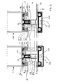
- FIG. 2 From the FIG. 2 are respectively sectional views of the post as well as release bolts in the area of FIG. 1 described with letter X point.
- Run-off latch 18 shown on the right is shown in FIG FIG. 2 shown rotated by 90 °.
- Post profile 1 and drain latch 18 are made of metal z. B. made of steel and have at their ends an attachment profile 29, which in the in FIG. 2 illustrated embodiment z. B. is designed as aluminum profile.
- a one-piece seal 6 is placed, which has a two-sided contact area 19 and common central area 21.
- the attachment of the seal 6 on the attachment profile 29 via a provided in the contact area 19, recessed area 30, in which a projection 31 of the attachment profile 29 on both sides of the attachment profile is located between the respective contact area 19 and central area 21 29 intervenes.
- outside holding element 5 On the outside of the post section 1 there is an outside holding element 5 which, with the interposition of an outside seal 8, fixes a glass pane 3 or a facade element 4 from the outside.
- the outside holding member 5 is this by means of a screw 37 with the Attachment profile 29 bolted.
- a cover 22 On the outside holding member 5, a cover 22 is clipped.
- the construction of the seal 36 in the region of the drain bolt 18 is identical in principle to the structure of the seal 6 on the post profile 1.
- the seal differs only in that the plane B of the respective drainage channel 12 is different on the side of the drain bolt 18, ie in Case of representation after FIG. 2 further inside than the plane A of the seal 6 of the post section. 1
- one side of the middle part 21 of the seal 36 of the drain bolt 18 is integrally formed a drain skirt 14 for the controlled discharge of the water collected in the drainage channel 12 of the drain bolt 18.
- FIG. 3 corresponds to the embodiment according to FIG. 2 with the difference that in FIG. 3 Instead of an attachment profile made of aluminum, a steel attachment profile is used.
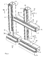
- both the seal 7 on the vertical bar profile 11 and the horizontal bar profile 10 is processed, ie provided with a notched area 34, so that the Seal 7 with the drainage channel 16 (water-carrying channel) rests on the seal 7 of the horizontal latch profile 10 to form an overlap region 35.
- a notched portion 34 is provided in the transfer of the drainage channel 12 of the horizontal bar profile 10 in the drainage channel 13 of the post section 1 .
- the levels of the individual drainage channels are each in different levels AD to each other.
- drain skirt 14 On the drain bolt 18 is integrally formed on the central region 21 of the seal 36 of the drain bolt 18, a drain skirt 14 over the entire length of the seal 36. It causes a controlled passage of the collected water in the drainage channel 17 over the rabbet width outward.
- facade according to the invention or the roof according to the invention it is possible to provide facades or roofs with effective drainage with increased design options available.
- the invention therefore represents a very significant contribution in the relevant field of technology.
Description
- Die vorliegende Erfindung betrifft eine Fassade oder ein Dach mit den Merkmalen des Oberbegriffs des Anspruchs 1.
- Die
DE 100 35 772 A1 beschreibt eine Pfosten-Riegel-Konstruktion unter Verwendung einer Aufsatzdichtung, welche mittels eines Adapterprofils an der Stirnseite eines Pfosten- bzw. Riegelprofils anbringbar ist. Die Aufsatzdichtung beinhaltet einen Entwässerungskanal zur Überleitung von im Riegelbereich anfallendem Sickerwasser in die Entwässerungsnut der Aufsatzdichtung des Pfostens. Die Dichtungen werden hierbei jeweils im Überlappungsbereich ausgeklinkt. Das vom Pfosten jeweils aufgefangene Wasser wird über dessen Entwässerungskanal über die gesamte Höhe des Bauwerks nach unten geleitet. Entsprechende Fassadenkonstruktionen sind auch aus derEP 1 078 135 B 1 sowieEP 0 692 586 B 1 bekannt. Derartige Fassadenkonstruktionen haben den Nachteil, dass aufgrund der vertikalen, über die Pfosten erfolgenden Entwässerung den Gestaltungsmöglichkeiten der Fassade Grenzen gesetzt sind, insbesondere Fassadenwechsel nur unter Schwierigkeiten möglich sind, sofern eine wirksame Entwässerung der Fassade beibehalten bleiben soll. - Die Aufgabe der vorliegenden Erfindung besteht darin, eine neuartige Fassade oder Dach zu schaffen, bei der die Gestaltungsmöglichkeiten einer Fassade oder eines Dachs bei Beibehaltung einer wirksamen Entwässerung erheblich erweitert werden können.
- Die vorstehende Aufgabe wird bei der gattungsgemäßen Fassade oder dem Dach dadurch gelöst, dass die Entwässerungskanäle der Pfostenprofile in einen Entwässerungskanal eines Ablaufriegels münden. Der Erfindung liegt die Idee zugrunde, durch Einsatz eines Ablaufriegels Fassadenabschnitte getrennt voneinander entwässern zu können. Hierdurch kann der Ablauf des in einem Fassadenbereich gesammelten Wassers über die Höhe der Fassade variabel gestaltet werden (z. B. geschoßweise Entwässerung). Dies wiederum ermöglicht eine erheblich variablere Fassadengestaltung als bisher ermöglicht.
- Zweckmäßigerweise ist der Ablaufriegel der unterste Riegel am ersten Rahmenwerk oder eines Abschnitts davon. Der durch den Ablaufriegel gebildete waagrechte Sammelkanal kann also demnach entweder an der Unterseite der Fassade oder aber an der Unterseite lediglich eines Fassadenabschnitts vorgesehen sein.
- Um eine einfach zu realisierende Überleitung der Entwässerungskanäle zu gewährleisten, kann weiterhin zweckmäßigerweise vorgesehen sein, dass die Ebene D des Entwässerungskanals des Ablaufriegels in einer zu den Ebenen A und B der Entwässerungskanäle des Pfostenprofils bzw. Riegelprofils unterschiedlichen Ebene liegt.
- Gemäß einer weiteren Ausgestaltung der vorliegenden Erfindung sind zusätzlich zu den waagrechten Riegelprofilen senkrechte Riegelprofile vorgesehen, die das erste Rahmenwerk in ein kleineres, zweites Rahmenwerk unterteilen, wobei sich die Entwässerungsebene der senkrechten Riegelprofile wiederum zu den Entwässerungsebenen A, B und D unterscheidet. Hierdurch wird bei insgesamt vier unterschiedlichen Entwässerungsebenen A bis D eine sehr hohe Gestaltungsvariabilität der Fassade erreicht.
- Zur wirksamen Entwässerung sind vorzugsweise Dichtungen vorgesehen, mit denen die Entwässerungskanäle in unterschiedlichen Ebenen gebildet werden können.
- Die Dichtungen werden hierzu zweckmäßigerweise so ausgeführt, dass im Bereich der Überleitung eines Entwässerungskanals die Dichtung des wasserführenden Kanals über das Ende des Pfostenprofils bzw. waagrechten Riegelprofils übersteht, die Dichtung des benachbarten Pfostenprofils bzw. waagrechten Riegelprofils bzw. Ablaufriegels überlappt und die beiden zueinander benachbarten Dichtungen im Überlappungsbereich jeweils ausgeklinkt sind. Somit ist zur Überleitung der Entwässerungskanäle lediglich ein Ausklinken der Dichtungen, nicht allerdings ein Ausklinken der Profile notwendig.
- Die Dichtungen für das Pfosten- und/oder Riegelprofil und/oder für den Ablaufriegel besitzen neben einem außen befindlichen Anlagebereich einen von Letzteren begrenzten innen liegenden Kanalbereich auf jeder Seite. Die beiden Kanalbereiche zu beiden Seiten der Stirnseite der Dichtung sind zweckmäßigerweise von einem gemeinsamen Mittelbereich begrenzt und die beidseitigen Anlagebereiche sowie Kanalbereiche einschließlich des gemeinsamen Mittelbereichs einteilig ausgebildet.
- Im Mittelbereich der Dichtung kann sich in vorteilhafter Weise eine durch zwei Querstege gebildete Luftkammer befinden. Zusätzlich kann eine zur Fassadeninnenseite hin orientierte Ausnehmung mit mittig befindlichem Vorsprung am Mittelbereich vorgesehen sein, um die Fixierung der Dichtung zu erleichtern.
- Zur Fixierung der Dichtung am Pfostenprofil und/oder Riegelprofil und/oder Ablaufriegel sind zweckmäßigerweise Aufsatzprofile z. B. aus Aluminiumoder Stahl vorgesehen. Die Profile von Pfosten, Riegel und Ablaufriegel bestehen beispielsweise aus Stahl.
- Gemäß einer zweckmäßigen Ausgestaltung der vorliegenden Erfindung ist im Bereich des Ablaufriegels eine zur Außenseite hin orientierte Ablaufschürze vorgesehen. Diese Ablaufschürze gewährleistet eine Überleitung des im Entwässerungskanals des Ablaufriegels aufgefangenen Wassers über die Falzbreite hinweg zur Außenseite.
- Die Ablaufschürze ist zweckmäßigerweise an die Dichtung für den Ablaufriegel angeformt. Eine geeignete Stelle hierfür ist insbesondere der Mittelbereich der Dichtung.
- Eine zweckmäßige Ausgestaltung der vorliegenden Erfindung wird nachstehend anhand der Zeichnungsfiguren näher erläutert. Es zeigen:
- Fig. 1
- eine stark vereinfachte, schematische Darstellungsweise eines erfindungsgemäßen Fassadenabschnittes unter Realisierung von insgesamt vier Entwässerungsebenen A-D;
- Fig. 2
- eine Schnittdarstellung durch eine Ausgestaltung der Fassade im Bereich des Pfostens sowie Ablaufriegels (um 90° gedreht);
- Fig. 3
- eine Schnittdarstellung durch die Fassade im Bereich des Pfostens und des Ablaufriegels (um 90° gedreht) einer weiteren Ausgestaltung der vorliegenden Erfindung sowie
- Fig. 4
- eine schematische Darstellung in perspektivischer Sicht eines Teils einer erfindungsgemäßen Fassade.
-
Figur 1 zeigt in stark vereinfachter Darstellungsweise den Abschnitt einer erfindungsgemäßen Fassade. Die Fassade wird gebildet durch senkrecht stehende Pfostenprofile 1 sowie waagrecht liegende Riegelprofile 10, die ein erstes Rahmenwerk 2 bilden. Das erste Rahmenwerk 2 besitzt im linken Bereich der inFigur 1 dargestellten Fassade breitere Ausfachungen als im rechten Bereich. Des weiteren umfaßt die Fassade senkrecht stehende Riegelprofile 11, die bereichsweise das erste Rahmenwerk 2 in ein zweites, mit kleineren Ausfachungen versehenes zweites Rahmenwerk 15 unterteilen. An der Unterseite der inFigur 1 dargestellten Fassade befindet sich ein Ablaufriegel 18. - Die Ebenen der Entwässerungskanäle des Pfostenprofils 1, Riegelprofils 10, senkrechten Riegelprofils 11 sowie Ablaufriegels 18 liegen in zueinander unterschiedlichen Ebenen A-D. Die Fassade nach
Figur 1 umfaßt somit insgesamt vier unterschiedliche Ebenen von Entwässerungskanälen. - Aus der
Figur 2 sind jeweils Schnittdarstellungen des Pfostens sowie Ablaufriegels im Bereich der inFigur 1 mit Buchstaben X gekennzeichneten Stelle beschrieben. Der inFigur 2 rechts dargestellte Ablaufriegel 18 ist aus Darstellungszwecken inFigur 2 um 90° gedreht dargestellt. Pfostenprofil 1 und Ablaufriegel 18 bestehen aus Metall z. B. aus Stahl und weisen an ihren Stirnseiten ein Aufsatzprofil 29 auf, welches in der inFigur 2 dargestellten Ausführungsform z. B. als Aluminiumprofil ausgebildet ist. Auf das Aufsatzprofil 29 des Pfostenprofils 1 wird eine einteilige Dichtung 6 aufgesetzt, welche einen beidseitigen Anlagebereich 19 sowie gemeinsamen Mittelbereich 21 aufweist. Zwischen dem jeweiligen Anlagebereich 19 und Mittelbereich 21 befinden sich auf jeder Seite ein Entwässerungskanal 13. Die Befestigung der Dichtung 6 am Aufsatzprofil 29 erfolgt über einen im Anlagebereich 19 vorgesehenen, ausgesparten Bereich 30, in den ein Vorsprung 31 des Aufsatzprofils 29 zu beiden Seiten des Aufsatzprofils 29 eingreift. - Darüber hinaus liegt im Mittelbereich 21 der Dichtung 6 eine durch zwei Querstege 25, 26 gebildete Kammer sowie ein mittiger Vorsprung, der in eine entsprechende Ausnehmung 27 des Aufsatzprofils 29 eingreift und eine zusätzliche Fixierung der Dichtung 6 gewährleistet.
- An der Außenseite des Pfostenprofils 1 befindet sich ein außenseitiges Halteelement 5, welches unter Zwischenschaltung einer außenseitigen Dichtung 8 eine Glasscheibe 3 oder ein Fassadenelement 4 von der Außenseite her fixiert. Das außenseitige Halteelement 5 wird hierzu mittels einer Schraube 37 mit dem Aufsatzprofil 29 verschraubt. Auf das außenseitige Halteelement 5 wird eine Abdeckung 22 aufgeklipst.
- Am jeweiligen Anlagebereich 19 sind Einschnitte 32 und 33 vorgesehen.
- Der Aufbau der Dichtung 36 im Bereich des Ablaufriegels 18 ist im Prinzip identisch zu dem Aufbau der Dichtung 6 am Pfostenprofil 1. Die Dichtung unterscheidet sich lediglich darin, dass die Ebene B des jeweiligen Entwässerungskanals 12 auf der Seite des Ablaufriegels 18 unterschiedlich ist, d. h. im Falle der Darstellung nach
Figur 2 weiter innen liegt als die Ebene A der Dichtung 6 des Pfostenprofils 1. - Darüber hinaus befindet sich einseitig am Mittelteil 21 der Dichtung 36 des Ablaufriegels 18 angeformt eine Ablaufschürze 14 zur kontrollierten Ableitung des im Entwässerungskanals 12 des Ablaufriegels 18 aufgefangenen Wassers.
- Die Ausgestaltung gemäß
Figur 3 entspricht der Ausgestaltung gemäßFigur 2 mit dem Unterschied, dass inFigur 3 anstelle eines Aufsatzprofils aus Aluminium ein Aufsatzprofil aus Stahl verwendet wird. - Aus der
Figur 4 wird die Überleitung der Entwässerungskanäle deutlich. Zur Gewährleistung einer Überführung von Wasser aus dem Entwässerungskanal 16 des senkrechten Riegelprofils 11 in den Entwässerungskanal 12 des waagrechten Riegelprofils 10 wird sowohl die Dichtung 7 am senkrechten Riegelprofil 11 als auch am waagrechten Riegelprofil 10 bearbeitet, d. h. mit einem ausgeklinkten Bereich 34 versehen, so dass die Dichtung 7 mit dem Entwässerungskanal 16 (wasserzuführender Kanal) unter Bildung eines Überlappungsbereichs 35 auf der Dichtung 7 des waagrechten Riegelprofils 10 aufliegt. - Bei der Überleitung des Entwässerungskanals 12 des waagrechten Riegelprofils 10 in den Entwässerungskanal 13 des Pfostenprofils 1 ist ebenfalls ein ausgeklinkter Bereich 34 vorgesehen. Gleiches gilt für die Überleitungen des Entwässerungskanals 13 des Pfostenprofils 1 (wasserzuführender Kanal) bzw. des Entwässerungskanals 16 (wasserzuführender Kanal) des senkrechten Riegelprofils 11 in den Entwässerungskanal 17 des Ablaufriegels 18. Wie in
Figur 4 verdeutlicht ist, befinden sich die Ebenen der einzelnen Entwässerungskanäle jeweils in unterschiedlichen Ebenen A-D zueinander. - An dem Ablaufriegel 18 ist einstückig an den Mittelbereich 21 der Dichtung 36 des Ablaufriegels 18 eine Ablaufschürze 14 über die Gesamtlänge der Dichtung 36 angeformt. Sie bewirkt ein kontrolliertes Überleiten des im Entwässerungskanal 17 aufgefangenen Wassers über die Falzbreite hinweg nach außen.
- Mit der erfindungsgemäßen Fassade bzw. dem erfindungsgemäßen Dach wird es möglich, Fassaden oder Dächer mit wirksamer Entwässerung mit erhöhten Gestaltungsmöglichkeiten zur Verfügung zu stellen. Die Erfindung stellt daher einen ganz wesentlichen Beitrag auf dem einschlägigen Gebiet der Technik dar.
Claims (14)
- Fassade oder Dach mit
Pfostenprofilen (1),
im Wesentlichen waagrecht zu den Pfostenprofilen (1) verlaufenden Riegelprofilen (10), wobei die Pfostenprofile (1) und waagrechten Riegelprofile (10) zum Aufbau eines ersten Rahmenwerks (2) dienen, dessen Ausfachungen mit Füllelementen, insbesondere Glasscheiben (3) und/oder Fassadenpaneelen (4) und/oder dergleichen ausfüllbar sind, außenseitigen Halteelementen (5),
innen liegenden Dichtungen (6, 7, 36), die sich zwischen Füllelement und Pfostenprofil (1) bzw. waagrechtem Riegelprofil (10) befinden,
außen liegenden Dichtungen (8, 9), die sich jeweils zwischen Füllelement und außenseitigem Halteelement befinden,
Entwässerungskanälen (13) im Bereich des Pfostenprofils (1) Entwässerungskanälen (12) im Bereich des waagrechten Riegelprofils (10), wobei die Entwässerungskanäle (12) des waagrechten Riegelprofils (10) sich in einer von der Ebene A der Entwässerungskanäle (13) des Pfostenprofils (1) unterschiedlichen Ebene B befinden und jeweils in die Entwässerungskanäle (13) des Pfostenprofils (1) münden, so dass Wasser in den Entwässerungskanälen (12) des waagrechten Riegelprofils (10) in die jeweiligen Entwässerungskanäle (13) des Pfostenprofils (1) überführbar ist,
dadurch gekennzeichnet, dass
die Entwässerungskanäle (13) der Pfostenprofile (1) in einen Entwässerungskanal (17) eines Ablaufriegels (18) münden. - Fassade oder Dach nach Anspruch 1,
dadurch gekennzeichnet, dass
der Ablaufriegel (18) der unterste Riegel am ersten Rahmenwerk (2) oder eines Abschnitts davon ist. - Fassade oder Dach nach Anspruch 1 oder 2,
dadurch gekennzeichnet, dass
die Ebene D des Entwässerungskanals (17) des Ablaufriegels (18) in einer Ebene liegt, die sich von den Ebenen A und B unterscheidet. - Fassade oder Dach nach einem der vorhergehenden Ansprüche,
dadurch gekennzeichnet, dass
zusätzlich zu den waagrechten Riegelprofilen (10) senkrechte Riegelprofile (11) vorgesehen sind, die das jeweils aus Pfostenprofil (1) und waagrechtem Riegelprofil (10) gebildete erste Rahmenwerk (2) in ein kleineres, zweites Rahmenwerk (15) unterteilen,
Entwässerungskanäle (16) an den senkrechten Riegelprofilen (11) vorgesehen sind, die in die Entwässerungskanäle (12) der waagrechten Riegelprofile (10) münden, so dass das Wasser aus den Entwässerungskanälen (16) der senkrechten Riegelprofile (11) in die Entwässerungskanäle (12) der waagrechten Riegelprofile (10) überführbar ist. - Fassade oder Dach nach Anspruch 4,
dadurch gekennzeichnet, dass
die Ebene der Entwässerungskanäle (16) des senkrechten Riegelprofils (14) in einer unterschiedlichen Ebene C zu den Ebenen A, B und D liegt. - Fassade oder Dach nach einem der vorhergehenden Ansprüche ,
dadurch gekennzeichnet, dass
Pfostenprofile (1), waagrechten Riegelprofile (10) und senkrechten Riegelprofile (14) sowie Ablaufriegel (18) in derselben Ebene liegen und die unterschiedlichen Ebenen der Entwässerungskanäle (12, 13, 16, 17) durch die zugehörigen Dichtungen (6, 7, 36) festgelegt sind. - Fassade oder Dach nach Anspruch 6,
dadurch gekennzeichnet, dass
im Bereich der Überleitung eines Entwässerungskanals (z. B. 12) die Dichtung (z. B. 7) des wasserzuführenden Kanals über das Ende des Pfostenprofils (1) bzw. waagrechten Riegelprofils (10) übersteht, die Dichtung (z. B. 6, 7, 36) des benachbarten Pfostenprofils (1) bzw. waagrechten Riegelprofils (10) bzw. Ablaufriegels (18) überlappt und die beiden benachbarten Dichtungen (z. B. 6und7) im Überlappungsbereich (35) jeweils ausgeklinkt sind. - Fassade oder Dach nach einem der vorhergehenden Ansprüche,
dadurch gekennzeichnet, dass
die Dichtung (6) für das Pfostenprofil (1) und/oder die Dichtung (7) für das jeweilige Riegelprofil (10, 11) und/oder die Dichtung (36) für den Ablaufriegel (18) neben einem außen befindlichen Anlagebereich (19) einen von Letzteren begrenzten innen liegenden Kanalbereich (20) aufweist. - Fassade oder Dach nach Anspruch 8,
dadurch gekennzeichnet, dass
die Kanalbereiche (19) zu beiden Seiten der Stirnseite von Pfostenprofil (1) und/oder Riegelprofil (10, 11) und/oder Ablaufriegel (18) von einem gemeinsamen Mittelbereich (21) begrenzt sind und die beidseitigen Anlagebereiche (19) sowie Kanalbereiche (20) sowie der gemeinsame Mittelbereich (21) einteilig ausgebildet sind. - Fassade oder Dach nach Anspruch 9,
dadurch gekennzeichnet, dass
der Mittelbereich (21) eine durch zwei Querstege (25, 26) gebildete Luftkammer aufweist. - Fassade oder Dach nach Anspruch 9 oder 10,
dadurch gekennzeichnet, dass
der Mittelbereich (21) eine zur Fassadeninnenseite hin orientierte Ausnehmung (27) mit mittig befindlichem Vorsprung (28) aufweist. - Fassade oder Dach nach einem der vorhergehenden Ansprüche,
dadurch gekennzeichnet, dass
an dem Pfostenprofil (1) und/oder Riegelprofil (10, 11) und/oder Ablaufriegel (18) Aufsatzprofile (29) vorgesehen sind. - Fassade oder Dach nach einem der vorhergehenden Ansprüche,
dadurch gekennzeichnet, dass
im Bereich des Ablaufriegels (18) eine zur Außenseite hin orientierte Ablaufschürze (14) vorgesehen ist. - Fassade oder Dach nach Anspruch 13,
dadurch gekennzeichnet, dass
die Ablaufschürze (14) an der Dichtung (36) für den Ablaufriegel (18), insbesondere an deren Mittelbereich (21), angeformt ist.
Priority Applications (2)
| Application Number | Priority Date | Filing Date | Title |
|---|---|---|---|
| PL04008685T PL1471191T3 (pl) | 2003-04-25 | 2004-04-10 | Elewacja lub dach z wieloma powierzchniami odwadniającymi |
| SI200431831T SI1471191T1 (sl) | 2003-04-25 | 2004-04-10 | Fasada ali streha z več nivoji za odvajanje vode |
Applications Claiming Priority (2)
| Application Number | Priority Date | Filing Date | Title |
|---|---|---|---|
| DE10319001A DE10319001B4 (de) | 2003-04-25 | 2003-04-25 | Fassade oder Dach mit mehreren Entwässerungsebenen |
| DE10319001 | 2003-04-25 |
Publications (3)
| Publication Number | Publication Date |
|---|---|
| EP1471191A2 EP1471191A2 (de) | 2004-10-27 |
| EP1471191A3 EP1471191A3 (de) | 2009-09-23 |
| EP1471191B1 true EP1471191B1 (de) | 2012-01-18 |
Family
ID=32946450
Family Applications (1)
| Application Number | Title | Priority Date | Filing Date |
|---|---|---|---|
| EP04008685A Revoked EP1471191B1 (de) | 2003-04-25 | 2004-04-10 | Fassade oder Dach mit mehreren Entwässerungsebenen |
Country Status (5)
| Country | Link |
|---|---|
| EP (1) | EP1471191B1 (de) |
| AT (1) | ATE541998T1 (de) |
| DE (1) | DE10319001B4 (de) |
| PL (1) | PL1471191T3 (de) |
| SI (1) | SI1471191T1 (de) |
Cited By (1)
| Publication number | Priority date | Publication date | Assignee | Title |
|---|---|---|---|---|
| US20150284951A1 (en) * | 2014-02-24 | 2015-10-08 | Todd Frederick | Curtain wall mullions, transoms and systems |
Families Citing this family (8)
| Publication number | Priority date | Publication date | Assignee | Title |
|---|---|---|---|---|
| DE102005001986A1 (de) * | 2005-01-15 | 2006-07-20 | SCHÜCO International KG | Modulare Fassade für Gebäude, Glasauflagedichtung und Schraube |
| DE202007012348U1 (de) * | 2007-09-04 | 2009-01-08 | Rehau Ag + Co | Tragwerk für eine Gebäudefassade |
| DE202007012347U1 (de) * | 2007-09-04 | 2009-01-08 | Rehau Ag + Co | Tragwerk für eine Gebäudefassade |
| DE102007053659A1 (de) * | 2007-11-08 | 2009-05-20 | Hermann Gutmann Werke Ag | Gebäudefassade in Brandschutzausführung |
| EP2243890A1 (de) | 2009-03-25 | 2010-10-27 | Alcoa Aluminium Deutschland, Inc. | Adapterelement für die wärmedämmende Sanierung von Pfosten-Riegel-Fassaden, eine Fassade mit einem derartigen Adapterelement und Verfahren zur Sanierung von Pfosten-Riegel-Fassaden |
| BE1018867A3 (nl) * | 2009-08-21 | 2011-10-04 | Avonts Smet Techniek En Ind Nv | Openschuivend dak. |
| DE102012001722A1 (de) * | 2012-01-31 | 2013-08-01 | Christian Lehmann | Gebäudewand mit Glaselementen |
| CN112814235B (zh) * | 2021-01-08 | 2022-09-20 | 北京住总第二开发建设有限公司 | 一种分层导流开放式石材幕墙施工方法 |
Family Cites Families (10)
| Publication number | Priority date | Publication date | Assignee | Title |
|---|---|---|---|---|
| GB2143558B (en) * | 1983-06-28 | 1987-10-28 | Pearce & Cutler Limited | Curtain walling system |
| GB2167099A (en) * | 1984-11-17 | 1986-05-21 | Planet Windows | Water drainage in curtain walling |
| GB8609171D0 (en) * | 1986-04-15 | 1986-05-21 | Const Utilities Group Ltd | Curtain walling |
| DE3703650C2 (de) * | 1987-02-06 | 1996-01-04 | Baukonstruktionen Ges Gbk | Glasfassade bzw. Glasdach mit Drainage für zwischen den Falzen der Glasfelder verbleibende hohle Falzräume |
| DE3736305A1 (de) * | 1987-10-27 | 1989-05-11 | Metallbau Philippi Gerd Gmbh | Elastisches zwischenprofil eines glasdaches oder einer glaswand |
| DE4000769A1 (de) * | 1990-01-12 | 1991-07-18 | Reynolds Aluminium Deutschland | Traggerippe fuer eine oder an einer fassadenwand |
| DE4332406A1 (de) * | 1993-09-23 | 1995-03-30 | Heroal Johann Henkenjohann Gmb | Pfosten-Riegel-System |
| DE9411552U1 (de) * | 1994-07-16 | 1994-11-10 | Raico Bautechnik Gmbh | Fassade |
| DE19822103A1 (de) * | 1998-05-11 | 1999-12-02 | Mannesmann Ag | Fassadensystem für die Verkleidung eines Bauwerkes |
| DE10035772A1 (de) * | 2000-07-22 | 2002-01-31 | Schueco Int Kg | Aufsatzdichtung für eine Pfosten-/Riegel-Konstruktion |
-
2003
- 2003-04-25 DE DE10319001A patent/DE10319001B4/de not_active Expired - Fee Related
-
2004
- 2004-04-10 PL PL04008685T patent/PL1471191T3/pl unknown
- 2004-04-10 EP EP04008685A patent/EP1471191B1/de not_active Revoked
- 2004-04-10 AT AT04008685T patent/ATE541998T1/de active
- 2004-04-10 SI SI200431831T patent/SI1471191T1/sl unknown
Cited By (2)
| Publication number | Priority date | Publication date | Assignee | Title |
|---|---|---|---|---|
| US20150284951A1 (en) * | 2014-02-24 | 2015-10-08 | Todd Frederick | Curtain wall mullions, transoms and systems |
| US9212482B2 (en) | 2014-02-24 | 2015-12-15 | Steelglaze, Inc. | Curtain wall mullions, transoms and systems |
Also Published As
| Publication number | Publication date |
|---|---|
| EP1471191A3 (de) | 2009-09-23 |
| SI1471191T1 (sl) | 2012-04-30 |
| DE10319001B4 (de) | 2008-11-06 |
| EP1471191A2 (de) | 2004-10-27 |
| ATE541998T1 (de) | 2012-02-15 |
| PL1471191T3 (pl) | 2012-06-29 |
| DE10319001A1 (de) | 2004-12-02 |
Similar Documents
| Publication | Publication Date | Title |
|---|---|---|
| DE3419538C2 (de) | ||
| EP1471191B1 (de) | Fassade oder Dach mit mehreren Entwässerungsebenen | |
| EP3715561B1 (de) | Überdachungssystem sowie trägermodul hierfür | |
| DE3735016C1 (en) | Frame structure by the post/crossmember construction method, in particular for facades, roofs or the like | |
| DE69917898T2 (de) | Rahmenstruktur zum einbau zwischen zwei übereinander angeordneten balkonplatten | |
| DE2330370A1 (de) | Schiebefenster bzw. schiebetuer | |
| EP0298328B1 (de) | Fassadenwand | |
| DE10223038A1 (de) | Fassadenkonstruktion mit einem durch ein Dichtelement abgedichteten Riegelseitigen Isolierprofil | |
| WO2011067210A2 (de) | Schiebewand mit wenigstens zwei flügeln | |
| DE102015120940A1 (de) | Flachdachfenster in Schwenkflügelbauart | |
| EP0414105B1 (de) | Vorrichtung zur Entwässerung insbesondere von Schräg- und Dachverglasung | |
| EP1020576A2 (de) | Fassade oder Lichtdach mit einem Rahmenwerk aus Pfosten- und Sprossenprofilen | |
| DE10027283A1 (de) | Kraftfahrzeugtür | |
| EP1577455B1 (de) | Gebäudefassade oder Dach mit Ausfachungen zur Aufnahme von Fassadenelementen | |
| EP0433236B1 (de) | Tragkonstruktion für Dachabdeckung | |
| DE19613044A1 (de) | Pfosten-Sprossen-Konstruktion | |
| EP2072744B1 (de) | Zargenprofil für eine Hebe-Schiebetür | |
| DE202004005204U1 (de) | Schiebetür | |
| DE102007033984A1 (de) | Blendrahmenkonstruktion sowie Blendrahmenanordnung | |
| DE102022206444B4 (de) | Blendrahmen für eine Tür mit Extrusionsrahmen und Schwelle, Tür mit einem derartigen Blendrahmen und Verfahren zur Herstellung dieser Tür | |
| EP4102021B1 (de) | Fenster- oder tür-hohlkammerprofil, system mit einem solchen hohlkammerprofil und daraus hergestellter rahmen | |
| EP3879059B1 (de) | Bodenschwelle | |
| EP3045603B1 (de) | Pfosten-riegel-konstruktion | |
| EP4245957A1 (de) | Türrahmen mit bodenschwelle | |
| EP3558782B1 (de) | Fahrzeug mit einer türschwelle |
Legal Events
| Date | Code | Title | Description |
|---|---|---|---|
| PUAI | Public reference made under article 153(3) epc to a published international application that has entered the european phase |
Free format text: ORIGINAL CODE: 0009012 |
|
| AK | Designated contracting states |
Kind code of ref document: A2 Designated state(s): AT BE BG CH CY CZ DE DK EE ES FI FR GB GR HU IE IT LI LU MC NL PL PT RO SE SI SK TR |
|
| AX | Request for extension of the european patent |
Extension state: AL HR LT LV MK |
|
| RAP1 | Party data changed (applicant data changed or rights of an application transferred) |
Owner name: HERMANN GUTMANN WERKE AG |
|
| PUAL | Search report despatched |
Free format text: ORIGINAL CODE: 0009013 |
|
| AK | Designated contracting states |
Kind code of ref document: A3 Designated state(s): AT BE BG CH CY CZ DE DK EE ES FI FR GB GR HU IE IT LI LU MC NL PL PT RO SE SI SK TR |
|
| AX | Request for extension of the european patent |
Extension state: AL HR LT LV MK |
|
| 17P | Request for examination filed |
Effective date: 20100317 |
|
| AKX | Designation fees paid |
Designated state(s): AT BE BG CH CY CZ DE DK EE ES FI FR GB GR HU IE IT LI LU MC NL PL PT RO SE SI SK TR |
|
| RAP1 | Party data changed (applicant data changed or rights of an application transferred) |
Owner name: GUTMANN AG |
|
| RAP1 | Party data changed (applicant data changed or rights of an application transferred) |
Owner name: GUTMANN AG |
|
| GRAP | Despatch of communication of intention to grant a patent |
Free format text: ORIGINAL CODE: EPIDOSNIGR1 |
|
| RIC1 | Information provided on ipc code assigned before grant |
Ipc: E04B 2/96 20060101AFI20110713BHEP Ipc: E06B 7/14 20060101ALI20110713BHEP Ipc: E04D 3/08 20060101ALN20110713BHEP |
|
| GRAS | Grant fee paid |
Free format text: ORIGINAL CODE: EPIDOSNIGR3 |
|
| GRAA | (expected) grant |
Free format text: ORIGINAL CODE: 0009210 |
|
| AK | Designated contracting states |
Kind code of ref document: B1 Designated state(s): AT BE BG CH CY CZ DE DK EE ES FI FR GB GR HU IE IT LI LU MC NL PL PT RO SE SI SK TR |
|
| REG | Reference to a national code |
Ref country code: GB Ref legal event code: FG4D Free format text: NOT ENGLISH |
|
| REG | Reference to a national code |
Ref country code: CH Ref legal event code: EP |
|
| REG | Reference to a national code |
Ref country code: IE Ref legal event code: FG4D Free format text: LANGUAGE OF EP DOCUMENT: GERMAN Ref country code: AT Ref legal event code: REF Ref document number: 541998 Country of ref document: AT Kind code of ref document: T Effective date: 20120215 |
|
| REG | Reference to a national code |
Ref country code: DE Ref legal event code: R096 Ref document number: 502004013238 Country of ref document: DE Effective date: 20120315 Ref country code: CH Ref legal event code: NV Representative=s name: PATENTANWAELTE SCHAAD, BALASS, MENZL & PARTNER AG |
|
| REG | Reference to a national code |
Ref country code: RO Ref legal event code: EPE |
|
| REG | Reference to a national code |
Ref country code: SK Ref legal event code: T3 Ref document number: E 11225 Country of ref document: SK |
|
| REG | Reference to a national code |
Ref country code: NL Ref legal event code: VDEP Effective date: 20120118 |
|
| REG | Reference to a national code |
Ref country code: EE Ref legal event code: FG4A Ref document number: E006601 Country of ref document: EE Effective date: 20120220 |
|
| REG | Reference to a national code |
Ref country code: PL Ref legal event code: T3 |
|
| PG25 | Lapsed in a contracting state [announced via postgrant information from national office to epo] |
Ref country code: NL Free format text: LAPSE BECAUSE OF FAILURE TO SUBMIT A TRANSLATION OF THE DESCRIPTION OR TO PAY THE FEE WITHIN THE PRESCRIBED TIME-LIMIT Effective date: 20120118 |
|
| PGFP | Annual fee paid to national office [announced via postgrant information from national office to epo] |
Ref country code: CH Payment date: 20120423 Year of fee payment: 9 Ref country code: HU Payment date: 20120417 Year of fee payment: 9 Ref country code: LU Payment date: 20120424 Year of fee payment: 9 Ref country code: BG Payment date: 20120423 Year of fee payment: 9 Ref country code: BE Payment date: 20120424 Year of fee payment: 9 Ref country code: EE Payment date: 20120423 Year of fee payment: 9 Ref country code: CZ Payment date: 20120404 Year of fee payment: 9 Ref country code: DE Payment date: 20120416 Year of fee payment: 9 Ref country code: SK Payment date: 20120410 Year of fee payment: 9 |
|
| REG | Reference to a national code |
Ref country code: IE Ref legal event code: FD4D |
|
| PG25 | Lapsed in a contracting state [announced via postgrant information from national office to epo] |
Ref country code: GR Free format text: LAPSE BECAUSE OF FAILURE TO SUBMIT A TRANSLATION OF THE DESCRIPTION OR TO PAY THE FEE WITHIN THE PRESCRIBED TIME-LIMIT Effective date: 20120419 Ref country code: PT Free format text: LAPSE BECAUSE OF FAILURE TO SUBMIT A TRANSLATION OF THE DESCRIPTION OR TO PAY THE FEE WITHIN THE PRESCRIBED TIME-LIMIT Effective date: 20120518 Ref country code: FI Free format text: LAPSE BECAUSE OF FAILURE TO SUBMIT A TRANSLATION OF THE DESCRIPTION OR TO PAY THE FEE WITHIN THE PRESCRIBED TIME-LIMIT Effective date: 20120118 |
|
| PGFP | Annual fee paid to national office [announced via postgrant information from national office to epo] |
Ref country code: RO Payment date: 20120409 Year of fee payment: 9 Ref country code: PL Payment date: 20120404 Year of fee payment: 9 |
|
| PG25 | Lapsed in a contracting state [announced via postgrant information from national office to epo] |
Ref country code: CY Free format text: LAPSE BECAUSE OF FAILURE TO SUBMIT A TRANSLATION OF THE DESCRIPTION OR TO PAY THE FEE WITHIN THE PRESCRIBED TIME-LIMIT Effective date: 20120118 |
|
| PGFP | Annual fee paid to national office [announced via postgrant information from national office to epo] |
Ref country code: IT Payment date: 20120428 Year of fee payment: 9 |
|
| PLBI | Opposition filed |
Free format text: ORIGINAL CODE: 0009260 |
|
| REG | Reference to a national code |
Ref country code: HU Ref legal event code: AG4A Ref document number: E014001 Country of ref document: HU |
|
| PG25 | Lapsed in a contracting state [announced via postgrant information from national office to epo] |
Ref country code: SE Free format text: LAPSE BECAUSE OF FAILURE TO SUBMIT A TRANSLATION OF THE DESCRIPTION OR TO PAY THE FEE WITHIN THE PRESCRIBED TIME-LIMIT Effective date: 20120118 Ref country code: IE Free format text: LAPSE BECAUSE OF FAILURE TO SUBMIT A TRANSLATION OF THE DESCRIPTION OR TO PAY THE FEE WITHIN THE PRESCRIBED TIME-LIMIT Effective date: 20120118 Ref country code: DK Free format text: LAPSE BECAUSE OF FAILURE TO SUBMIT A TRANSLATION OF THE DESCRIPTION OR TO PAY THE FEE WITHIN THE PRESCRIBED TIME-LIMIT Effective date: 20120118 |
|
| PGFP | Annual fee paid to national office [announced via postgrant information from national office to epo] |
Ref country code: SI Payment date: 20120405 Year of fee payment: 9 |
|
| 26 | Opposition filed |
Opponent name: SCHUECO INTERNATIONAL KG Effective date: 20121011 |
|
| PLAX | Notice of opposition and request to file observation + time limit sent |
Free format text: ORIGINAL CODE: EPIDOSNOBS2 |
|
| PG25 | Lapsed in a contracting state [announced via postgrant information from national office to epo] |
Ref country code: MC Free format text: LAPSE BECAUSE OF NON-PAYMENT OF DUE FEES Effective date: 20120430 |
|
| GBPC | Gb: european patent ceased through non-payment of renewal fee |
Effective date: 20120418 |
|
| REG | Reference to a national code |
Ref country code: DE Ref legal event code: R026 Ref document number: 502004013238 Country of ref document: DE Effective date: 20121011 |
|
| REG | Reference to a national code |
Ref country code: FR Ref legal event code: ST Effective date: 20121228 |
|
| PG25 | Lapsed in a contracting state [announced via postgrant information from national office to epo] |
Ref country code: GB Free format text: LAPSE BECAUSE OF NON-PAYMENT OF DUE FEES Effective date: 20120418 |
|
| PG25 | Lapsed in a contracting state [announced via postgrant information from national office to epo] |
Ref country code: FR Free format text: LAPSE BECAUSE OF NON-PAYMENT OF DUE FEES Effective date: 20120430 |
|
| PGFP | Annual fee paid to national office [announced via postgrant information from national office to epo] |
Ref country code: AT Payment date: 20120420 Year of fee payment: 9 |
|
| PG25 | Lapsed in a contracting state [announced via postgrant information from national office to epo] |
Ref country code: ES Free format text: LAPSE BECAUSE OF FAILURE TO SUBMIT A TRANSLATION OF THE DESCRIPTION OR TO PAY THE FEE WITHIN THE PRESCRIBED TIME-LIMIT Effective date: 20120429 |
|
| BERE | Be: lapsed |
Owner name: GUTMANN A.G. Effective date: 20130430 |
|
| REG | Reference to a national code |
Ref country code: CH Ref legal event code: PL |
|
| REG | Reference to a national code |
Ref country code: AT Ref legal event code: MM01 Ref document number: 541998 Country of ref document: AT Kind code of ref document: T Effective date: 20130430 |
|
| REG | Reference to a national code |
Ref country code: EE Ref legal event code: MM4A Ref document number: E006601 Country of ref document: EE Effective date: 20130430 |
|
| REG | Reference to a national code |
Ref country code: SK Ref legal event code: MM4A Ref document number: E 11225 Country of ref document: SK Effective date: 20130410 |
|
| RDAF | Communication despatched that patent is revoked |
Free format text: ORIGINAL CODE: EPIDOSNREV1 |
|
| PG25 | Lapsed in a contracting state [announced via postgrant information from national office to epo] |
Ref country code: DE Free format text: LAPSE BECAUSE OF NON-PAYMENT OF DUE FEES Effective date: 20131101 Ref country code: BE Free format text: LAPSE BECAUSE OF NON-PAYMENT OF DUE FEES Effective date: 20130430 Ref country code: SK Free format text: LAPSE BECAUSE OF NON-PAYMENT OF DUE FEES Effective date: 20130410 Ref country code: EE Free format text: LAPSE BECAUSE OF NON-PAYMENT OF DUE FEES Effective date: 20130430 Ref country code: CZ Free format text: LAPSE BECAUSE OF NON-PAYMENT OF DUE FEES Effective date: 20130410 Ref country code: AT Free format text: LAPSE BECAUSE OF NON-PAYMENT OF DUE FEES Effective date: 20130430 Ref country code: CH Free format text: LAPSE BECAUSE OF NON-PAYMENT OF DUE FEES Effective date: 20130430 Ref country code: LI Free format text: LAPSE BECAUSE OF NON-PAYMENT OF DUE FEES Effective date: 20130430 |
|
| REG | Reference to a national code |
Ref country code: DE Ref legal event code: R119 Ref document number: 502004013238 Country of ref document: DE Effective date: 20131101 |
|
| PG25 | Lapsed in a contracting state [announced via postgrant information from national office to epo] |
Ref country code: SI Free format text: LAPSE BECAUSE OF NON-PAYMENT OF DUE FEES Effective date: 20130411 Ref country code: HU Free format text: LAPSE BECAUSE OF NON-PAYMENT OF DUE FEES Effective date: 20130411 Ref country code: RO Free format text: LAPSE BECAUSE OF NON-PAYMENT OF DUE FEES Effective date: 20130410 Ref country code: IT Free format text: LAPSE BECAUSE OF NON-PAYMENT OF DUE FEES Effective date: 20130410 |
|
| REG | Reference to a national code |
Ref country code: SI Ref legal event code: KO00 Effective date: 20140116 |
|
| RDAG | Patent revoked |
Free format text: ORIGINAL CODE: 0009271 |
|
| STAA | Information on the status of an ep patent application or granted ep patent |
Free format text: STATUS: PATENT REVOKED |
|
| PG25 | Lapsed in a contracting state [announced via postgrant information from national office to epo] |
Ref country code: TR Free format text: LAPSE BECAUSE OF FAILURE TO SUBMIT A TRANSLATION OF THE DESCRIPTION OR TO PAY THE FEE WITHIN THE PRESCRIBED TIME-LIMIT Effective date: 20120118 |
|
| 27W | Patent revoked |
Effective date: 20140124 |
|
| REG | Reference to a national code |
Ref country code: SK Ref legal event code: MC4A Ref document number: E 11225 Country of ref document: SK Effective date: 20140124 |
|
| REG | Reference to a national code |
Ref country code: PL Ref legal event code: LAPE |
|
| REG | Reference to a national code |
Ref country code: EE Ref legal event code: MF4A Ref document number: E006601 Country of ref document: EE Effective date: 20140527 Ref country code: AT Ref legal event code: MA03 Ref document number: 541998 Country of ref document: AT Kind code of ref document: T Effective date: 20140124 |
|
| PG25 | Lapsed in a contracting state [announced via postgrant information from national office to epo] |
Ref country code: PL Free format text: LAPSE BECAUSE OF NON-PAYMENT OF DUE FEES Effective date: 20130410 |
|
| PG25 | Lapsed in a contracting state [announced via postgrant information from national office to epo] |
Ref country code: LU Free format text: LAPSE BECAUSE OF NON-PAYMENT OF DUE FEES Effective date: 20130410 |
|
| PG25 | Lapsed in a contracting state [announced via postgrant information from national office to epo] |
Ref country code: BG Free format text: LAPSE BECAUSE OF NON-PAYMENT OF DUE FEES Effective date: 20121231 |