EP3558068B1 - System zur aufhängung eines vorhangs - Google Patents
System zur aufhängung eines vorhangs Download PDFInfo
- Publication number
- EP3558068B1 EP3558068B1 EP17818116.0A EP17818116A EP3558068B1 EP 3558068 B1 EP3558068 B1 EP 3558068B1 EP 17818116 A EP17818116 A EP 17818116A EP 3558068 B1 EP3558068 B1 EP 3558068B1
- Authority
- EP
- European Patent Office
- Prior art keywords
- curtain
- guide track
- insert
- guide
- suspension
- Prior art date
- Legal status (The legal status is an assumption and is not a legal conclusion. Google has not performed a legal analysis and makes no representation as to the accuracy of the status listed.)
- Active
Links
Images

Classifications
-
- A—HUMAN NECESSITIES
- A47—FURNITURE; DOMESTIC ARTICLES OR APPLIANCES; COFFEE MILLS; SPICE MILLS; SUCTION CLEANERS IN GENERAL
- A47H—FURNISHINGS FOR WINDOWS OR DOORS
- A47H1/00—Curtain suspension devices
- A47H1/04—Curtain rails
-
- A—HUMAN NECESSITIES
- A47—FURNITURE; DOMESTIC ARTICLES OR APPLIANCES; COFFEE MILLS; SPICE MILLS; SUCTION CLEANERS IN GENERAL
- A47H—FURNISHINGS FOR WINDOWS OR DOORS
- A47H15/00—Runners or gliders for supporting curtains on rails or rods
- A47H15/02—Runners
-
- A—HUMAN NECESSITIES
- A47—FURNITURE; DOMESTIC ARTICLES OR APPLIANCES; COFFEE MILLS; SPICE MILLS; SUCTION CLEANERS IN GENERAL
- A47H—FURNISHINGS FOR WINDOWS OR DOORS
- A47H15/00—Runners or gliders for supporting curtains on rails or rods
- A47H15/04—Gliders
Definitions
- the present invention relates to a system for suspension of a curtain device, comprising at least one curtain guide and at least one curtain or the like that is suspended on a plurality of suspension units with a guide element for guiding a suspension unit along the curtain guide.
- a known objection of systems for suspension of a curtain device is the noise caused by the movement of the suspension units along the curtain guide. Even if the noise is small, it can be disturbing. For example, in a hospital, in operating rooms, in theaters or cinemas or even in private space the noise of opening and closing a curtain device is undesirable.
- the curtain guide for guiding and/or supporting an object provides at least one guide rail or track.
- the curtain guide track can be an elongated profile element or can comprise curved sections.
- the curtain guide also described as guide track or rail or profile element can be of substantially circular, oval, rectangular or other cross-section with any reasonable size.
- the curtain guide comprises at least a guide track providing a bearing surface for slidably mounting the guide elements.
- curtain guide tracks are known wherein at least one slot is formed in the guide track and open to the external surface of the guide track supporting a plurality of gliders or sliders or guide elements for movement along the guide track.
- a known guide track can be formed with a hollow extruded track having an inside bearing surface wherein guide elements are moveably mounted for supporting a slidable curtain or the like and wherein the guide track opposite edges projecting from the side walls limit the width of the longitudinal track slot and an inner face forms sliding surfaces for internal guide elements, wherein said surfaces are inclined towards the track slot.
- a guide track has a cross-section including generally upright web having a perpendicular base flange on which the guide elements can ride.
- a suspension unit used in the system comprises at least a suspension element to which a curtain device or the like can be secured and a guide element for guiding in or at the guide track.
- the suspension element is used to support a curtain hook which is fitted into a pocket in a heading tape secured to a curtain.
- the guide element i.e. the component moveable along the guide track of a curtain guide, is formed to slide on or in the track provided by the guide track. Furthermore, a guide element is formed as a roller to travel along the guide track on wheels or rollers.
- the guide element can be made of fiber, hard leather or other material which will serve the purpose and afford a minimum of friction and noise in use.
- a guide element can be made also of synthetic plastic material, wherein it is formed with sliding surfaces convex in shape and wherein through the friction between the sliding surfaces of the guide track and the guide element a more durable wearing surface of the guide element is obtained to achieve noiseless movement thereof.
- a guide element from a thin metal strip covered by a wrap of textile fiber, wherein the fabric can be woven, knitted or braided or felted.
- Known guide elements are made from metal wherein those parts of the guide element touching the guide rail may be faced or shod with an anti-friction material, i.e. the material can only cover essential parts of the guide elements.
- guide elements providing a substantially silent movement within or at the guide track by providing at essentially contact surfaces silencing materials. Therefore, guide elements are known comprising a rigid body to which at one end a pair of rollers having tires formed of rubber or other deformable and preferably silencing material.
- cushions which slidably engage parts of the guide track in a manner to limit lateral swinging and silencing engagement of the guide element with parts of the guide track during opening and closing of the curtains.
- the cushions can be arranged in recesses formed at the contact portions between guide track and guide element.
- DE 11 39 950 B discloses a curtain rail and guide elements whereby contact surfaces between them are provided with inserts of a solid material with lubrication properties, poured or inserted in grooves made in the contact surfaces to provide a sliding surface.
- JP 2001 061642 A relates to a curtain rail and a runner whereby a coating of a damping material is applied on a sliding face.
- JP H07 34787 U relates to a curtain rail comprising a groove-like fitting portion, in which a separate member made of synthetic resin fits providing a running surface.
- JP H08 89393 A relates to a curtain rail provided with a soft resin layer on the runner travel face.
- the object of the present invention is therefore to propose a system for suspension of a curtain device comprising a guide track and a slidably mounted guide element to reduce the noise of the movement of the guide elements along the guide track, i.e. to provide a smooth and silent movement which is almost noiseless.
- a further object is to propose a system for suspension of a curtain device which can be used with gliders formed to slide on the guide track as well as rollers adapted to roll on such track surfaces.
- a still further object is that the guide element can have different shapes and forms and can be made of plastic material as molding.
- a system for suspension of a curtain device comprising at least one curtain guide track and at least one curtain or the like that is suspended on a plurality of suspension units, wherein the suspension units each comprise a guide element for guiding a respective suspension unit along the curtain guide track, wherein the curtain guide track and the guide element each provide a bearing surface.
- the bearing surface of the guide track provides the sliding or rolling surface on which the guide element is moved by sliding or rolling along, wherein the guide element comprises a bearing surface providing engagement with the guide track, i.e. the bearing surface of the guide track.
- a silencing material is provided to reduce friction and noise.
- the silencing material, showing damping properties is formed as an insert received in recesses formed on the bearing surface of the guide element and/or the guide track which are made of a rigid material, wherein the insert is made of a softer material than the rigid material of the guide element and/or the guide track.
- the system is characterized in that a coating or a thin layer, each of a more rigid material than the material of the insert is provided on the sliding surfaces of the guide element and/or the guide track to improve the gliding properties.
- the system is characterized in that the guide element provides recesses formed as a notch substantially parallel to the sliding surfaces to accommodate the silencing material formed as an insert made of a softer material than the material of the guide element.
- the expression bearing surface complies as well the bearing surface as at least partly a part adjacently to the bearing surface.
- the silencing material can be chosen from a group comprising fiber composites, synthetic materials, wood and textile. Application of silencing material at least on one of the bearing surfaces reduces significantly the noise caused by moving guide elements along guide tracks.
- the preferred silencing material is a fiber composite, mostly preferred felt.
- felt means a material made of matted and compressed fibers, pressed together using heat, moisture and/or pressure, wherein natural fibers such as wool or synthetic fibers such as polyamide, polyester etc. can be used.
- Felt is a material offering a wide versatility. Felt is an excellent sound insulator showing superb vibration damping properties. Felt is a vibration dampener mostly because its stress-deformation curve forms a hysterics loop, soaking most of the energy. Felt is highly resilient, retaining its strength and unique properties for a long time. Felt can be cut in any size, shape or thickness or can be heat formed and run through dies which will form it into shapes. Felt can be bonded to most surfaces.
- the silencing material may be impregnated with graphite, wax or other suitable lubricant.
- felt can be impregnated because of its reservoir properties. Felt can absorb and hold several times of its weight in various fluids, including lubricants. The ability of transfer the lubricant as needed to bearing surfaces through the felt makes felt an ideal lubricator.
- a silencing material is provided as a coating on at least one of the bearing surfaces of either the guide track or the guide element or both of them.
- the coating can be build up by application of the silencing material on at least one of the bearing surfaces for example by spraying.
- the silencing material as an insert can be attached to the bearing surfaces by adhesion, welding and/or injection-molding, furthermore by crimping, rolled -in.
- the silencing material is formed as an insert received in recesses formed on the bearing surfaces of the guide track and/or the guide element or both.
- the insert is made of a silencing material showing damping properties, wherein the insert is accommodated at the guide element made of a rigid material.
- the silencing material formed as an insert is accommodated in a notch formed at the guide element, formed substantially parallel to the sliding surfaces.
- the insert is made of a softer material as the rigid material of the guide element wherein sliding surfaces are made of the rigid material.
- the silencing material formed as an insert is accommodated such that the silencing material provides sliding surfaces.
- each of a more rigid material is provided on the sliding surfaces of such an insert.
- the silencing material formed as an insert is attached by pressing into a recess provided at least on one of the bearing surfaces.
- the recess is formed on the bearing surface of the guide element.
- the guide element can be of roller-type comprising a rigid body having an externally essentially cylindrical transverse portion within a transverse shaft is journaled. This shaft carries at its opposite ends a pair of rollers having wheels or rollers formed of another material than the rigid body.
- the material for the wheels may be a silencing material.
- the bearing surface of the wheels are provided with a recess to insert a silencing material in this recess.
- the guide element comprises a body providing a recess for receiving an insert made of the silencing material.
- the insert received in the recess can be secured by an end cap which is connectable to the body such as to hold the insert in position.
- the guide elements can be made of suitable plastic material, such as thermoplastic polymers as polypropylene, polyoxymethylen (acetal) or polyamide or compounding further comprising for example polytetrafluorethylene (PTFE). Furthermore, the guide element can be formed by two-component injection molding.
- suitable plastic material such as thermoplastic polymers as polypropylene, polyoxymethylen (acetal) or polyamide or compounding further comprising for example polytetrafluorethylene (PTFE).
- PTFE polytetrafluorethylene
- the guide element can be formed by two-component injection molding.
- the guide elements are formed as gliders for sliding along the guide track.
- Guide elements are retained by the track for sliding or rolling movement along it.
- the guide element can be suitable for internal and external sliding or rolling depending on the type of the track and the guide element.
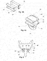
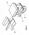
- Fig. 1A shows the guide element 10 having a body 12 with outwardly extending wings defining recesses 14 for cooperation with edges of a slot provided in a guide track (not shown).
- the body 12 of each guide element 10 has a depending eye 16 for receiving a curtain hook (not shown).
- the guide elements 10 may be molded in one piece so as to have upper and lower horizontal walls 18, 20 respectively of which the wings constitute extensions, joined by forward and rear vertical walls 22.
- upper and lower refer to orientations with the guide elements supported by the track arranged in horizontally orientation.
- the opposing faces of the wing extensions of the upper and the lower walls 18, 20 which define recesses 14 are preferably slightly convex. Therefore, the spacing between the front and the rear vertical walls 22 of the guide element 10 increase to simplify the insertion of such a guide element 10 into the track and travel along.
- the portion of the body 12 of the guide element which defines the eye 16 extends downwardly from the lower horizontal wall 20, the underside of which is channeled so that the eye 16 has a partly circular profile. Oher profiles for the eye 16 are possible, like rectangular etc.
- an insert 30 made of a silencing material is seen.
- the insert 30 can be received into one of the recesses 14 formed between the opposing faces of the wing extensions of the upper and lower walls 18, 20.
- This insert 30 is provided with a linear sliding surface 32 projecting laterally from a vertical wall 34 and extending throughout the length of the insert 30.
- the sliding surface 32 can be seen as a bearing surface.
- the sliding surface 32 is convex in shape as the shape of the recesses 14 of the guide element 10.
- the insert With the slightly convex shape of the opposing faces of the wing extensions of the upper and lower walls 18, 20 of the guide element 10 the insert can be secured in position. Furthermore, at the forward and/or rear vertical walls 22 of the body 12 an end part of the upper and lower walls 18, 20 i.e. the wing extensions can be formed such that the spacing between them is slightly reduced to provide a certain barrier to hold the insert in position.
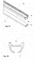
- a system for suspension of a curtain device comprising a tubular guide track 40 made of metal, for example aluminum alloy, or plastic material having a longitudinal extending slot 42 in its underside, defined by two opposed flanges 44 projecting from the side walls 46, wherein the parts 48 of the flanges 44 providing a bearing surface 50 for the guide element 10.
- the parts 48 can be formed as to slope towards the slot 42, for example the parts 44 can form segments of a circle.
- the slot 42 is at least as wide as the width of the clearance of the guide element 10, therefore the parts 48 of the flanges 44 are received into the recesses 14 of the guide element 10.
- the sliding surface 32, providing a bearing surface of the guide element 10 is adapted to engage with the bearing surface 50 of the guide track 40.
- Fig. 3A shows a tubular guide track 40 made of metal, for example aluminum alloy, or plastic material. Furthermore, it is shown an insert 41 formed to fit into the recess limited by the two opposed flanges 44 projecting from the side walls 46 of the guide track 40.
- the insert 41 can be made of any suitable silencing material.
- the insert 41 can be bonded in any appropriate way to the side walls 46 and the flanges 44 providing the bearing surface 50. Referring to fig. 3B the insert 41 is accommodated into the recess formed by the parts of the guide track 40 and bonded thereto.
- a guide element 10 not according to the invention is shown for illustration purposes only, wherein the guide element 10 is formed to correspond to an inversed T-shape guide track 40.
- the cross-section of the guide track 40 comprises a generally upright vertical wall 52 and a perpendicular base flange 54.
- the body of the guide element 10 is formed to provide a rectangular recess 14 partly opened, wherein the flange 54 of T-shape guide track 40 can be accommodated.
- the guide element 10 comprises the sliding surface 32 adapted to engage with bearing surfaces 50 of the basis flange 54 of the guide track 40.
- the sliding surface 32 can be provided by a coating of the walls of the recess 14 of the guide element 10 which are in contact with the bearing surface 50 of the guide track 40.
- bearing surfaces 50 can be coated wherein the coating can be achieved by dipping in or spraying or brushing with liquid thermoplastic on at least roller or glider tracks and on the surfaces against which faces of rollers or gliders will engage.
- bearing surfaces 50 for example of aluminum tracks can be impregnated with silicon fluid.
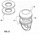
- the guide element 10 not according to the invention and present for illustration purposes only is formed as a cylindrical body 56 with a portion 58 of the body extending downwardly from a lower end of the cylindrical body 56 wherein in this downwardly extending portion 58 a ring 60 can be provided to receive a curtain hook (not shown).
- parts 62 of the surface of the guide element 10 which are adapted to engage with parts of the guide track 40 (not shown) are coated by a silencing material 64.
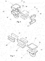
- the guide element 10 can comprise more than one piece wherein the pieces can be attached to each other to form the guide element 10 shown in fig. 1A .
- the body 12 of the guide element 10 comprises the upper horizontal wall 18 with the wing extension and the lower horizontal wall 20 with wing extension and between the upper and the lower horizontal walls spaced apart a longitudinal extending element 66 of widely rectangular cross-section, joined together at one of the forward or rear vertical walls 22.
- the body 12 of the guide element 10 forms the recess 14 for receiving the insert 30.
- One front side of the body 12 is opened and is adapted to receive the insert 30 which is formed to fit into the formed recess 14.
- the opened front side of the body 12 of the guide element 10 can be closed with an end cap 68 shaped with a double T-shape comprising upper and lower horizontal walls 18, 20 with wing extensions.
- the end cap 68 can be fixedly attached to the body 12 of the guide element 10 through pins 70 provided on the end cap 68 which can be fitted into holes 72 provided at the opened front side of the body 12 of the guide element 10 or vice versa.
- Fig. 7 shows another embodiment of the invention.
- the guide element 10 comprises a body 12 according to the embodiment of fig. 1A , made of a rigid material like polyoxymethylen or polyamide or the like.
- the body 12 has the outwardly extending wings 18, 20 defining the recesses 14.
- the recesses 14 are designed to accommodate an insert 30 which is made of damping material like a rubber material showing a shore hardness of a softer plastic.
- the shore A hardness scale measures the hardness of flexible mold rubbers that range in hardness from very soft to hard and from flexible to almost no flexibility. Preferably the shore A hardness is selected properly.
- the insert 30 is provided for absorbing vibrations and noise caused by gliding of the guide element 10 along the guide track 40 (not shown).
- the insert 30 is bonded in appropriate way into the recesses 14 of the body 12 of the guide element 10.
- the insert 30 is formed with outwardly extending wings related to the wings 18, 20 of the body 12.
- the insert 30 shows slightly convex surfaces 82.
- Shown in fig. 7 elements 90 are made of a more rigid material.
- the elements 90 are formed to be inserted in the recesses each formed by the upper and lower outwardly extending wings of the insert 30.
- the elements 90 arranged in the recesses formed in the insert 30 provide the slightly convex shaped linear surfaces 32.
- the elements 90 are formed with small wall thickness. Therefore, when accommodated into the insert 30 the elements 90 forms a thin layer or a coating adapted to provide the sliding surface 32.
- the thin layer or coating shows excellent gliding properties wherein the insert 30 can absorb the vibration and the noise.
- Fig. 8 shows an alternative embodiment of the invention.
- the guide element 10 formed with a round body comprises recesses 14 formed as a notch wherein the inserts 30 are accommodated and secured respectively.
- the sliding surfaces 32 are provided by the guide element 10 and are made preferably of a more rigid material than the material of the insert 30.
- Fig. 9 shows an alternative embodiment of the invention.
- the guide element 10 is in a form similar to the embodiment of fig. 1A .
- the guide element 10 comprises recesses 14 formed as notches accommodating the inserts 30.
- the inserts 30 are made of another material as the guide element 10 which is made of a rigid material. According to this embodiment the sliding surfaces 32 are formed by the guide element 10.
Landscapes
- Curtains And Furnishings For Windows Or Doors (AREA)
- Bearings For Parts Moving Linearly (AREA)
Claims (12)
- System zum Aufhängen einer Vorhanganordnung, wobei das System mindestens eine Vorhangführungsschiene (40) und mindestens einen Vorhang umfasst, welcher an einer Vielzahl von Aufhängeeinheiten aufgehängt ist, wobei die Aufhängeeinheiten jeweils ein Führungselement (10) umfassen, um die jeweilige Aufhängeeinheit entlang der Vorhangführungsschiene (40) zu führen,wobei die Vorhangführungsschiene (40) und das Führungselement (10) jeweils eine Lagerfläche (50) vorsehen,wobei ein Dämpfungsmaterial (64), welches Dämpfungseigenschaften zeigt, als ein Einsatz (30) geformt ist, der in Aufnahmen (14), ausgebildet an den Lagerflächen (50) des aus einem harten Material gefertigten Führungselements (10), aufgenommen ist,wobei der Einsatz (30) aus einem weicheren Material als das harte Material des Führungselements (10) gefertigt ist, undwobei das Dämpfungsmaterial (64) Gleitflächen bereitstelltdadurch gekennzeichnet, dasseine Beschichtung oder eine dünne Schicht jeweils aus einem härteren Material als das Material des Einsatzes (30) an den Gleitflächen (32) vorgesehen ist, um die Gleiteigenschaften zu verbessern.
- System zum Aufhängen einer Vorhanganordnung, wobei das System mindestens eine Vorhangführungsschiene (40) und mindestens einen Vorhang umfasst, welcher an einer Vielzahl von Aufhängeeinheiten aufgehängt ist, wobei die Aufhängeeinheiten jeweils ein Führungselement (10) umfassen, um die jeweilige Aufhängeeinheit entlang der Vorhangführungsschiene (40) zu führen,wobei die Vorhangführungsschiene (40) und das Führungselement (10) jeweils eine Lagerfläche (50) vorsehen,wobei ein Dämpfungsmaterial (64), welches Dämpfungseigenschaften zeigt, als ein Einsatz (30) geformt ist, der in Aufnahmen (14), ausgebildet in dem Körper (12) des aus einem harten Material gefertigten Führungselements (10), aufgenommen ist,wobei der Einsatz (30) aus einem weicheren Material als das harte Material des Führungselements (10) gefertigt istdadurch gekennzeichnet, dassGleitflächen (32) von dem Führungselement (10) vorgesehen sind, wobei die Aufnahmen (14) ausgebildet sind als eine Nut im Wesentlichen parallel zu den Gleitflächen (32).
- System zum Aufhängen einer Vorhanganordnung, wobei das System mindestens eine Vorhangführungsschiene (40) und mindestens einen Vorhang umfasst, welcher an einer Vielzahl von Aufhängeeinheiten aufgehängt ist, wobei die Aufhängeeinheiten jeweils ein Führungselement (10) umfassen, um die jeweilige Aufhängeeinheit entlang der Vorhangführungsschiene (40) zu führen,wobei die Vorhangführungsschiene (40) und das Führungselement (10) jeweils eine Lagerfläche (50) vorsehen,wobei ein Dämpfungsmaterial (64), welches Dämpfungseigenschaften zeigt, als ein Einsatz (41) geformt ist, der in Aufnahmen (14), ausgebildet an den Lagerflächen (50) der aus einem harten Material gefertigten Führungsschiene (40),wobei der Einsatz (41) aus einem weicheren Material als das harte Material der Führungsschiene (40) gefertigt ist, undwobei das Dämpfungsmaterial (64) Gleitflächen (32) vorsiehtdadurch gekennzeichnet, dasseine Beschichtung oder eine dünne Schicht aus einem härteren Material als das Material des Einsatzes (41) an den Gleitflächen (32) vorgesehen ist, um die Gleiteigenschaften zu verbessern.
- System zum Aufhängen einer Vorhanganordnung gemäss Anspruch 1, dadurch gekennzeichnet, dassein Dämpfungsmaterial (64), welches Dämpfungseigenschaften zeigt, als ein weiterer Einsatz (41) geformt ist, der in Aufnahmen (14), ausgebildet an der Lagerfläche (50) der aus einem harten Material gefertigten Führungsschiene (40), aufgenommen ist,der weitere Einsatz (41) der Führungsschiene (40) ist aus einem weicheren Material als das harte Material der Führungsschiene (40) gefertigt,wobei das Dämpfungsmaterial (64) beider Einsätze (30; 41) jeweils Gleitflächen (32) vorsieht, undeine Beschichtung oder eine dünne Schicht, jeweils aus einem härteren Material als das Material der Einsätze (30; 41) an den Gleitflächen (32) vorgesehen ist, um die Gleiteigenschaften zu verbessern.
- System zum Aufhängen einer Vorhanganordnung gemäss Anspruch 2,dadurch gekennzeichnet, dassein Dämpfungsmaterial (64), welches Dämpfungseigenschaften zeigt, als ein weiterer Einsatz (41) geformt ist, der in Aufnahmen (14), ausgebildet an der Lagerfläche (50) der Führungsschiene (40), aufgenommen ist,wobei die Führungsschiene (40) aus einem harten Material gefertigt ist,wobei der weitere Einsatz (41) der Führungsschiene (40) aus einem weicheren Material als das harte Material der Führungsschiene (40) gefertigt ist, undwobei die weiteren Gleitflächen (32) der Führungsschiene (40) mit einer Beschichtung oder einer dünnen Schicht versehen sind, jeweils aus einem härteren Material als der weitere Einsatz (41) der Führungsschiene (40), um die Gleiteigenschaften zu verbessern.
- System zum Aufhängen einer Vorhanganordnung nach einem der vorhergehenden Ansprüche, wobei das Dämpfungsmaterial (64) aus einem Faserverbundwerkstoff, Kunststoff, Holz oder Textil gefertigt ist.
- System zum Aufhängen einer Vorhanganordnung nach Anspruch 6, wobei das Dämpfungsmaterial (64) Filz ist.
- System zum Aufhängen einer Vorhanganordnung nach einem der vorhergehenden Ansprüche, wenn von einem der Ansprüche 1 und 3 abhängig, wobei das Dämpfungsmaterial (64) zumindest an einer der Lagerflächen (50) mittels Kleben, Schweissen, Spritzgiessen, Crimpen und/oder Einpressen befestigt ist.
- System zum Aufhängen einer Vorhanganordnung nach einem der Ansprüche 1, 3 oder 4, wobei ein Element (90), ausgebildet als dünne Schicht aus einem härteren Material als der Einsatz (30; 41), mit dem jeweiligen Einsatz (30; 41) verbunden ist, um die Gleitflächen vorzusehen.
- System zum Aufhängen einer Vorhanganordnung nach Anspruch 1, wobei das Führungselement (10) einen Körper (12) umfasst, welcher die Aufnahme (14) zum Aufnahmen des Einsatzes (30) vorsieht und eine Endkappe (68), die mit dem Körper (12) verbindbar ist, um den Einsatz (30) in der Aufnahme (14) zu sichern.
- System zum Aufhängen einer Vorhanganordnung nach Anspruch 1 oder 2, wobei das Führungselement (10) als ein Gleiter ausgebildet ist, um entlang der Vorhangführungsschiene (40) zu gleiten.
- System zum Aufhängen einer Vorhanganordnung nach Anspruch 1, wobei das Führungselement (10) ein Roller ist, um entlang der Vorhangführungsschiene (40) zu rollen.
Applications Claiming Priority (2)
| Application Number | Priority Date | Filing Date | Title |
|---|---|---|---|
| CH17002016 | 2016-12-21 | ||
| PCT/EP2017/082991 WO2018114650A1 (en) | 2016-12-21 | 2017-12-15 | System for suspension of a curtain |
Publications (2)
| Publication Number | Publication Date |
|---|---|
| EP3558068A1 EP3558068A1 (de) | 2019-10-30 |
| EP3558068B1 true EP3558068B1 (de) | 2022-09-07 |
Family
ID=58632104
Family Applications (1)
| Application Number | Title | Priority Date | Filing Date |
|---|---|---|---|
| EP17818116.0A Active EP3558068B1 (de) | 2016-12-21 | 2017-12-15 | System zur aufhängung eines vorhangs |
Country Status (8)
| Country | Link |
|---|---|
| US (1) | US10806288B2 (de) |
| EP (1) | EP3558068B1 (de) |
| JP (1) | JP2020501710A (de) |
| CN (1) | CN110087514B (de) |
| AU (1) | AU2017380895B2 (de) |
| DK (1) | DK3558068T3 (de) |
| ES (1) | ES2929387T3 (de) |
| WO (1) | WO2018114650A1 (de) |
Families Citing this family (6)
| Publication number | Priority date | Publication date | Assignee | Title |
|---|---|---|---|---|
| US11547233B2 (en) * | 2020-02-07 | 2023-01-10 | The Boeing Company | Quick loading curtain track for an aircraft cabin |
| US12234017B2 (en) | 2021-06-21 | 2025-02-25 | B/E Aerospace, Inc. | Redundant rail and carriage assembly |
| US12330788B2 (en) * | 2021-06-21 | 2025-06-17 | B/E Aerospace, Inc. | Carriage assembly with overload protection |
| US12133605B1 (en) * | 2023-05-04 | 2024-11-05 | Textron Innovations Inc. | Metal-reinforced curtain glide |
| US12545085B2 (en) * | 2023-11-07 | 2026-02-10 | Volvo Truck Corporation | Vehicle curtain system |
| DE202024105739U1 (de) | 2024-10-04 | 2026-01-08 | REHAU Industries SE & Co. KG | System, insbesondere zum Aufhängen einer Vorhanganordnung |
Family Cites Families (39)
| Publication number | Priority date | Publication date | Assignee | Title |
|---|---|---|---|---|
| US2966695A (en) * | 1957-07-15 | 1961-01-03 | James E Dwyer | Unitized severable drapery carriers |
| DE1139950B (de) * | 1960-12-21 | 1962-11-22 | Rudolf Stoerzbach | Vorhangschiene mit rollenden oder gleitenden Aufhaengern |
| US3187370A (en) * | 1961-11-22 | 1965-06-08 | Bruce J Bieda | Drapery hanger |
| US3342344A (en) * | 1966-07-15 | 1967-09-19 | Vogel Peterson Co | Hanger receptacle and garment suspension apparatus employing the same |
| US4356902A (en) * | 1977-10-17 | 1982-11-02 | Murphy Raymond J | Bearing and support |
| US4282630A (en) * | 1979-08-23 | 1981-08-11 | Toder Ellis I | Drapery carrier assembly |
| JP2821915B2 (ja) * | 1989-10-11 | 1998-11-05 | トーソー株式会社 | サイレントカーテン装置 |
| US5259520A (en) * | 1992-02-26 | 1993-11-09 | Zenith Products Corp. | Curtain rod assembly and cover |
| NL9200489A (nl) * | 1992-03-16 | 1993-10-18 | Bosgoed Groothandel B V | Gordijnophangstelsel, herinpasbaar gordijnophangorgaan, rail geschikt voor het stelsel en werkwijze voor het buigen van de rail. |
| NL9201903A (nl) * | 1992-11-02 | 1994-06-01 | Forest Group Nederland Bv | Gordijnrail en werkwijze voor de vervaardiging daarvan. |
| US5421059A (en) * | 1993-05-24 | 1995-06-06 | Leffers, Jr.; Murray J. | Traverse support rod |
| JPH0734787U (ja) * | 1993-12-20 | 1995-06-27 | トーソー株式会社 | 金属製サイレントカーテンレール |
| JPH0889393A (ja) * | 1994-09-21 | 1996-04-09 | Toso Co Ltd | 音の静かな金属製カーテンレール |
| JPH09291747A (ja) * | 1996-04-26 | 1997-11-11 | K G Partek Kk | 戸車用レール |
| CA2223852C (en) * | 1997-12-05 | 2004-01-20 | George Albert Neil | Track and hook arrangement for storing a variety of articles |
| JP2001061642A (ja) * | 1999-08-26 | 2001-03-13 | Sanshin Kogyo Kk | カーテン案内レール及びそのランナー |
| CN2794374Y (zh) * | 2005-01-28 | 2006-07-12 | 罗立津 | 静音窗帘杆 |
| FR2884125B1 (fr) * | 2005-04-12 | 2007-05-18 | Ykk France Sarl | Curseur de tringle a rideaux |
| US20070277944A1 (en) * | 2006-05-31 | 2007-12-06 | Hans Wu | Curtain track assembly |
| CN2902097Y (zh) * | 2006-06-20 | 2007-05-23 | 广东创明遮阳科技有限公司 | 静音窗帘装置 |
| US20150173549A1 (en) * | 2006-12-13 | 2015-06-25 | David Zahner | Track and Curtain System |
| CN103251297A (zh) * | 2006-12-13 | 2013-08-21 | 约翰·德维斯 | 轨道和幕帘系统 |
| US20080148526A1 (en) * | 2006-12-22 | 2008-06-26 | Robert Stephen Garcia | Drapery rod |
| GB0820632D0 (en) * | 2008-11-12 | 2008-12-17 | Seddon Ivor H | Drapery hardware |
| US20100294441A1 (en) * | 2009-05-20 | 2010-11-25 | Merlin Manufacturing, Inc. | Method and apparatus for curtain baton with positionable pin |
| DE202009010880U1 (de) * | 2009-08-13 | 2009-12-24 | Stehr, Werner | Vorhangschiene mit Gleitern |
| CH702648B1 (de) * | 2010-02-03 | 2014-08-29 | Casatex Gmbh | Vorhanggleiter als Gleitelement für Vorhangschienen. |
| US20120018106A1 (en) * | 2010-07-26 | 2012-01-26 | Susana Robledo | Disposable hospital curtain system with sliding curtain carriers for snap-in installation on existing ceiling tracks |
| US8316508B2 (en) * | 2011-02-03 | 2012-11-27 | Economy Tent International, Inc. | Removable track system and method for tent sidewalls |
| NL2007580C2 (nl) * | 2011-10-12 | 2013-04-15 | Thomas Regout B V | Gordijnrunner voorzien van contactelementen en een samenstel van een gordijnrail en een dergelijke gordijnrunner. |
| CN203341489U (zh) * | 2012-03-08 | 2013-12-18 | 简约帘幕有限公司 | 幕帘支承组件 |
| CN202874926U (zh) * | 2012-10-22 | 2013-04-17 | 浙江德裕科技有限公司 | 能够根据现场需要进行弯曲加工的铝合金轨道 |
| DE102013213996B4 (de) * | 2013-07-17 | 2019-11-07 | Siemens Healthcare Gmbh | C-Bogen-Lagervorrichtung und Röntgenbildgebungsgerät mit einer Käfigführung |
| CN203789658U (zh) * | 2014-02-27 | 2014-08-27 | 雅霖工业股份有限公司 | 吊挂滑座结构 |
| CN204071634U (zh) * | 2014-07-24 | 2015-01-07 | 南通中皋铝制品有限公司 | 窗帘用连接型轨道 |
| JP6423258B2 (ja) * | 2014-12-12 | 2018-11-14 | 株式会社スガモトテント | レール用ランナーの走行構造 |
| CN204708563U (zh) * | 2015-06-26 | 2015-10-21 | 绍兴县布之道纺织品有限公司 | 窗帘轨道 |
| US9700170B1 (en) * | 2015-12-30 | 2017-07-11 | Richard Kouts | Roller bearing system |
| CN106108583B (zh) * | 2016-08-05 | 2019-09-17 | 宁波杜亚机电技术有限公司 | 一种吊轮及应用有该吊轮的窗帘轨道 |
-
2017
- 2017-12-15 US US16/462,008 patent/US10806288B2/en active Active
- 2017-12-15 AU AU2017380895A patent/AU2017380895B2/en active Active
- 2017-12-15 ES ES17818116T patent/ES2929387T3/es active Active
- 2017-12-15 JP JP2019531959A patent/JP2020501710A/ja active Pending
- 2017-12-15 CN CN201780078890.XA patent/CN110087514B/zh active Active
- 2017-12-15 EP EP17818116.0A patent/EP3558068B1/de active Active
- 2017-12-15 WO PCT/EP2017/082991 patent/WO2018114650A1/en not_active Ceased
- 2017-12-15 DK DK17818116.0T patent/DK3558068T3/da active
Also Published As
| Publication number | Publication date |
|---|---|
| AU2017380895A1 (en) | 2019-05-30 |
| CN110087514B (zh) | 2021-12-28 |
| DK3558068T3 (da) | 2022-10-03 |
| AU2017380895B2 (en) | 2023-02-16 |
| EP3558068A1 (de) | 2019-10-30 |
| CN110087514A (zh) | 2019-08-02 |
| WO2018114650A1 (en) | 2018-06-28 |
| ES2929387T3 (es) | 2022-11-28 |
| US10806288B2 (en) | 2020-10-20 |
| US20190328166A1 (en) | 2019-10-31 |
| JP2020501710A (ja) | 2020-01-23 |
Similar Documents
| Publication | Publication Date | Title |
|---|---|---|
| EP3558068B1 (de) | System zur aufhängung eines vorhangs | |
| US8627811B1 (en) | Compound archery crossbow | |
| US9416819B2 (en) | Re-circulating ball sliding support assembly | |
| CA1307687C (en) | Handrail for transportation apparatus | |
| US3051318A (en) | Closet bar assembly | |
| US20170231413A1 (en) | Suspension Unit for a Curtain Device | |
| US7740406B2 (en) | Linear motion guide system with highly-tight sealing units | |
| US10232802B2 (en) | Vehicle interior panel with compressible layer of non-uniform thickness | |
| CN111465774B (zh) | 伸缩导轨 | |
| WO2015173581A1 (en) | Re-circulating ball sliding support assembly | |
| BR102013000717A2 (pt) | Assento para veículo e uso de um elemento de haste deslizante ondulado | |
| ATE521260T1 (de) | Auszugsführung eines schubkastens | |
| AU2009249849B2 (en) | Person conveying device, in particular escalator or moving sidewalk, comprising a handrail, and handrail for an escalator or a moving walkway | |
| US10816037B2 (en) | Seals for linear guides | |
| JP2006071094A5 (de) | ||
| ES2256982T3 (es) | Guia de deslizamiento para una pieza corrediza. | |
| CN216060127U (zh) | 一种用于窗帘轨道的伸缩装置 | |
| KR102668836B1 (ko) | 슬라이딩 테이블 구조 및 이를 포함하는 슬라이딩 테이블 | |
| US11547211B2 (en) | Arrangement for guiding at least one movable furniture part | |
| JP2017032058A5 (de) | ||
| CN109899400A (zh) | 线性滑轨的润滑装置及其组合结构 | |
| KR101654926B1 (ko) | 슬라이딩 도어의 롤러 회전장치 | |
| JP2022541933A (ja) | 引出しガイド用の走行キャリッジ | |
| JP2009085303A (ja) | 非循環式リニアガイド装置 | |
| JP2011230340A (ja) | 繊維含有樹脂成形体 |
Legal Events
| Date | Code | Title | Description |
|---|---|---|---|
| STAA | Information on the status of an ep patent application or granted ep patent |
Free format text: STATUS: UNKNOWN |
|
| STAA | Information on the status of an ep patent application or granted ep patent |
Free format text: STATUS: THE INTERNATIONAL PUBLICATION HAS BEEN MADE |
|
| PUAI | Public reference made under article 153(3) epc to a published international application that has entered the european phase |
Free format text: ORIGINAL CODE: 0009012 |
|
| STAA | Information on the status of an ep patent application or granted ep patent |
Free format text: STATUS: REQUEST FOR EXAMINATION WAS MADE |
|
| 17P | Request for examination filed |
Effective date: 20190614 |
|
| AK | Designated contracting states |
Kind code of ref document: A1 Designated state(s): AL AT BE BG CH CY CZ DE DK EE ES FI FR GB GR HR HU IE IS IT LI LT LU LV MC MK MT NL NO PL PT RO RS SE SI SK SM TR |
|
| AX | Request for extension of the european patent |
Extension state: BA ME |
|
| DAV | Request for validation of the european patent (deleted) | ||
| DAX | Request for extension of the european patent (deleted) | ||
| STAA | Information on the status of an ep patent application or granted ep patent |
Free format text: STATUS: EXAMINATION IS IN PROGRESS |
|
| 17Q | First examination report despatched |
Effective date: 20201009 |
|
| GRAP | Despatch of communication of intention to grant a patent |
Free format text: ORIGINAL CODE: EPIDOSNIGR1 |
|
| STAA | Information on the status of an ep patent application or granted ep patent |
Free format text: STATUS: GRANT OF PATENT IS INTENDED |
|
| INTG | Intention to grant announced |
Effective date: 20220405 |
|
| GRAS | Grant fee paid |
Free format text: ORIGINAL CODE: EPIDOSNIGR3 |
|
| GRAA | (expected) grant |
Free format text: ORIGINAL CODE: 0009210 |
|
| STAA | Information on the status of an ep patent application or granted ep patent |
Free format text: STATUS: THE PATENT HAS BEEN GRANTED |
|
| RAP3 | Party data changed (applicant data changed or rights of an application transferred) |
Owner name: SILENT GLISS INTERNATIONAL AG |
|
| AK | Designated contracting states |
Kind code of ref document: B1 Designated state(s): AL AT BE BG CH CY CZ DE DK EE ES FI FR GB GR HR HU IE IS IT LI LT LU LV MC MK MT NL NO PL PT RO RS SE SI SK SM TR |
|
| REG | Reference to a national code |
Ref country code: GB Ref legal event code: FG4D |
|
| REG | Reference to a national code |
Ref country code: CH Ref legal event code: EP Ref country code: AT Ref legal event code: REF Ref document number: 1516359 Country of ref document: AT Kind code of ref document: T Effective date: 20220915 |
|
| REG | Reference to a national code |
Ref country code: DE Ref legal event code: R096 Ref document number: 602017061586 Country of ref document: DE |
|
| REG | Reference to a national code |
Ref country code: IE Ref legal event code: FG4D |
|
| REG | Reference to a national code |
Ref country code: DK Ref legal event code: T3 Effective date: 20220928 |
|
| REG | Reference to a national code |
Ref country code: FI Ref legal event code: FGE |
|
| REG | Reference to a national code |
Ref country code: SE Ref legal event code: TRGR |
|
| REG | Reference to a national code |
Ref country code: NL Ref legal event code: FP |
|
| REG | Reference to a national code |
Ref country code: NO Ref legal event code: T2 Effective date: 20220907 |
|
| REG | Reference to a national code |
Ref country code: ES Ref legal event code: FG2A Ref document number: 2929387 Country of ref document: ES Kind code of ref document: T3 Effective date: 20221128 |
|
| REG | Reference to a national code |
Ref country code: LT Ref legal event code: MG9D |
|
| PG25 | Lapsed in a contracting state [announced via postgrant information from national office to epo] |
Ref country code: RS Free format text: LAPSE BECAUSE OF FAILURE TO SUBMIT A TRANSLATION OF THE DESCRIPTION OR TO PAY THE FEE WITHIN THE PRESCRIBED TIME-LIMIT Effective date: 20220907 Ref country code: LV Free format text: LAPSE BECAUSE OF FAILURE TO SUBMIT A TRANSLATION OF THE DESCRIPTION OR TO PAY THE FEE WITHIN THE PRESCRIBED TIME-LIMIT Effective date: 20220907 Ref country code: LT Free format text: LAPSE BECAUSE OF FAILURE TO SUBMIT A TRANSLATION OF THE DESCRIPTION OR TO PAY THE FEE WITHIN THE PRESCRIBED TIME-LIMIT Effective date: 20220907 |
|
| PG25 | Lapsed in a contracting state [announced via postgrant information from national office to epo] |
Ref country code: HR Free format text: LAPSE BECAUSE OF FAILURE TO SUBMIT A TRANSLATION OF THE DESCRIPTION OR TO PAY THE FEE WITHIN THE PRESCRIBED TIME-LIMIT Effective date: 20220907 Ref country code: GR Free format text: LAPSE BECAUSE OF FAILURE TO SUBMIT A TRANSLATION OF THE DESCRIPTION OR TO PAY THE FEE WITHIN THE PRESCRIBED TIME-LIMIT Effective date: 20221208 |
|
| PG25 | Lapsed in a contracting state [announced via postgrant information from national office to epo] |
Ref country code: SM Free format text: LAPSE BECAUSE OF FAILURE TO SUBMIT A TRANSLATION OF THE DESCRIPTION OR TO PAY THE FEE WITHIN THE PRESCRIBED TIME-LIMIT Effective date: 20220907 Ref country code: RO Free format text: LAPSE BECAUSE OF FAILURE TO SUBMIT A TRANSLATION OF THE DESCRIPTION OR TO PAY THE FEE WITHIN THE PRESCRIBED TIME-LIMIT Effective date: 20220907 Ref country code: PT Free format text: LAPSE BECAUSE OF FAILURE TO SUBMIT A TRANSLATION OF THE DESCRIPTION OR TO PAY THE FEE WITHIN THE PRESCRIBED TIME-LIMIT Effective date: 20230109 Ref country code: CZ Free format text: LAPSE BECAUSE OF FAILURE TO SUBMIT A TRANSLATION OF THE DESCRIPTION OR TO PAY THE FEE WITHIN THE PRESCRIBED TIME-LIMIT Effective date: 20220907 |
|
| PG25 | Lapsed in a contracting state [announced via postgrant information from national office to epo] |
Ref country code: SK Free format text: LAPSE BECAUSE OF FAILURE TO SUBMIT A TRANSLATION OF THE DESCRIPTION OR TO PAY THE FEE WITHIN THE PRESCRIBED TIME-LIMIT Effective date: 20220907 Ref country code: PL Free format text: LAPSE BECAUSE OF FAILURE TO SUBMIT A TRANSLATION OF THE DESCRIPTION OR TO PAY THE FEE WITHIN THE PRESCRIBED TIME-LIMIT Effective date: 20220907 Ref country code: IS Free format text: LAPSE BECAUSE OF FAILURE TO SUBMIT A TRANSLATION OF THE DESCRIPTION OR TO PAY THE FEE WITHIN THE PRESCRIBED TIME-LIMIT Effective date: 20230107 Ref country code: EE Free format text: LAPSE BECAUSE OF FAILURE TO SUBMIT A TRANSLATION OF THE DESCRIPTION OR TO PAY THE FEE WITHIN THE PRESCRIBED TIME-LIMIT Effective date: 20220907 |
|
| REG | Reference to a national code |
Ref country code: DE Ref legal event code: R097 Ref document number: 602017061586 Country of ref document: DE |
|
| PG25 | Lapsed in a contracting state [announced via postgrant information from national office to epo] |
Ref country code: AL Free format text: LAPSE BECAUSE OF FAILURE TO SUBMIT A TRANSLATION OF THE DESCRIPTION OR TO PAY THE FEE WITHIN THE PRESCRIBED TIME-LIMIT Effective date: 20220907 |
|
| PLBE | No opposition filed within time limit |
Free format text: ORIGINAL CODE: 0009261 |
|
| STAA | Information on the status of an ep patent application or granted ep patent |
Free format text: STATUS: NO OPPOSITION FILED WITHIN TIME LIMIT |
|
| REG | Reference to a national code |
Ref country code: AT Ref legal event code: UEP Ref document number: 1516359 Country of ref document: AT Kind code of ref document: T Effective date: 20220907 |
|
| 26N | No opposition filed |
Effective date: 20230608 |
|
| PG25 | Lapsed in a contracting state [announced via postgrant information from national office to epo] |
Ref country code: SI Free format text: LAPSE BECAUSE OF FAILURE TO SUBMIT A TRANSLATION OF THE DESCRIPTION OR TO PAY THE FEE WITHIN THE PRESCRIBED TIME-LIMIT Effective date: 20220907 Ref country code: LU Free format text: LAPSE BECAUSE OF NON-PAYMENT OF DUE FEES Effective date: 20221215 |
|
| PG25 | Lapsed in a contracting state [announced via postgrant information from national office to epo] |
Ref country code: IE Free format text: LAPSE BECAUSE OF NON-PAYMENT OF DUE FEES Effective date: 20221215 |
|
| PG25 | Lapsed in a contracting state [announced via postgrant information from national office to epo] |
Ref country code: HU Free format text: LAPSE BECAUSE OF FAILURE TO SUBMIT A TRANSLATION OF THE DESCRIPTION OR TO PAY THE FEE WITHIN THE PRESCRIBED TIME-LIMIT; INVALID AB INITIO Effective date: 20171215 |
|
| PG25 | Lapsed in a contracting state [announced via postgrant information from national office to epo] |
Ref country code: CY Free format text: LAPSE BECAUSE OF FAILURE TO SUBMIT A TRANSLATION OF THE DESCRIPTION OR TO PAY THE FEE WITHIN THE PRESCRIBED TIME-LIMIT Effective date: 20220907 |
|
| PG25 | Lapsed in a contracting state [announced via postgrant information from national office to epo] |
Ref country code: MK Free format text: LAPSE BECAUSE OF FAILURE TO SUBMIT A TRANSLATION OF THE DESCRIPTION OR TO PAY THE FEE WITHIN THE PRESCRIBED TIME-LIMIT Effective date: 20220907 |
|
| PG25 | Lapsed in a contracting state [announced via postgrant information from national office to epo] |
Ref country code: MC Free format text: LAPSE BECAUSE OF FAILURE TO SUBMIT A TRANSLATION OF THE DESCRIPTION OR TO PAY THE FEE WITHIN THE PRESCRIBED TIME-LIMIT Effective date: 20220907 |
|
| PG25 | Lapsed in a contracting state [announced via postgrant information from national office to epo] |
Ref country code: MC Free format text: LAPSE BECAUSE OF FAILURE TO SUBMIT A TRANSLATION OF THE DESCRIPTION OR TO PAY THE FEE WITHIN THE PRESCRIBED TIME-LIMIT Effective date: 20220907 |
|
| PG25 | Lapsed in a contracting state [announced via postgrant information from national office to epo] |
Ref country code: BG Free format text: LAPSE BECAUSE OF FAILURE TO SUBMIT A TRANSLATION OF THE DESCRIPTION OR TO PAY THE FEE WITHIN THE PRESCRIBED TIME-LIMIT Effective date: 20220907 |
|
| PG25 | Lapsed in a contracting state [announced via postgrant information from national office to epo] |
Ref country code: MT Free format text: LAPSE BECAUSE OF FAILURE TO SUBMIT A TRANSLATION OF THE DESCRIPTION OR TO PAY THE FEE WITHIN THE PRESCRIBED TIME-LIMIT Effective date: 20220907 |
|
| PG25 | Lapsed in a contracting state [announced via postgrant information from national office to epo] |
Ref country code: TR Free format text: LAPSE BECAUSE OF FAILURE TO SUBMIT A TRANSLATION OF THE DESCRIPTION OR TO PAY THE FEE WITHIN THE PRESCRIBED TIME-LIMIT Effective date: 20220907 |
|
| REG | Reference to a national code |
Ref country code: CH Ref legal event code: U11 Free format text: ST27 STATUS EVENT CODE: U-0-0-U10-U11 (AS PROVIDED BY THE NATIONAL OFFICE) Effective date: 20260101 |
|
| PGFP | Annual fee paid to national office [announced via postgrant information from national office to epo] |
Ref country code: DE Payment date: 20251211 Year of fee payment: 9 |
|
| PGFP | Annual fee paid to national office [announced via postgrant information from national office to epo] |
Ref country code: GB Payment date: 20251219 Year of fee payment: 9 |
|
| PGFP | Annual fee paid to national office [announced via postgrant information from national office to epo] |
Ref country code: AT Payment date: 20251222 Year of fee payment: 9 |
|
| PGFP | Annual fee paid to national office [announced via postgrant information from national office to epo] |
Ref country code: IT Payment date: 20251222 Year of fee payment: 9 Ref country code: FI Payment date: 20251223 Year of fee payment: 9 Ref country code: DK Payment date: 20251224 Year of fee payment: 9 |
|
| PGFP | Annual fee paid to national office [announced via postgrant information from national office to epo] |
Ref country code: NL Payment date: 20251219 Year of fee payment: 9 Ref country code: FR Payment date: 20251229 Year of fee payment: 9 |
|
| PGFP | Annual fee paid to national office [announced via postgrant information from national office to epo] |
Ref country code: BE Payment date: 20251219 Year of fee payment: 9 |
|
| PGFP | Annual fee paid to national office [announced via postgrant information from national office to epo] |
Ref country code: SE Payment date: 20251219 Year of fee payment: 9 |
|
| PGFP | Annual fee paid to national office [announced via postgrant information from national office to epo] |
Ref country code: ES Payment date: 20260130 Year of fee payment: 9 |
|
| PGFP | Annual fee paid to national office [announced via postgrant information from national office to epo] |
Ref country code: NO Payment date: 20251230 Year of fee payment: 9 |
|
| PGFP | Annual fee paid to national office [announced via postgrant information from national office to epo] |
Ref country code: CH Payment date: 20260101 Year of fee payment: 9 |