EP3558068B1 - System for suspension of a curtain - Google Patents
System for suspension of a curtain Download PDFInfo
- Publication number
- EP3558068B1 EP3558068B1 EP17818116.0A EP17818116A EP3558068B1 EP 3558068 B1 EP3558068 B1 EP 3558068B1 EP 17818116 A EP17818116 A EP 17818116A EP 3558068 B1 EP3558068 B1 EP 3558068B1
- Authority
- EP
- European Patent Office
- Prior art keywords
- curtain
- guide track
- insert
- guide
- suspension
- Prior art date
- Legal status (The legal status is an assumption and is not a legal conclusion. Google has not performed a legal analysis and makes no representation as to the accuracy of the status listed.)
- Active
Links
- 239000000725 suspension Substances 0.000 title claims description 37
- 239000000463 material Substances 0.000 claims description 91
- 230000030279 gene silencing Effects 0.000 claims description 36
- 239000011248 coating agent Substances 0.000 claims description 13
- 238000000576 coating method Methods 0.000 claims description 13
- 238000013016 damping Methods 0.000 claims description 10
- 239000000835 fiber Substances 0.000 claims description 7
- 238000005096 rolling process Methods 0.000 claims description 6
- 239000002131 composite material Substances 0.000 claims description 3
- 238000001746 injection moulding Methods 0.000 claims description 3
- 229920002994 synthetic fiber Polymers 0.000 claims description 3
- 239000004753 textile Substances 0.000 claims description 3
- 238000002788 crimping Methods 0.000 claims description 2
- 238000003466 welding Methods 0.000 claims description 2
- 239000002023 wood Substances 0.000 claims description 2
- 239000004033 plastic Substances 0.000 description 6
- 229910052751 metal Inorganic materials 0.000 description 4
- 239000002184 metal Substances 0.000 description 4
- -1 polypropylene Polymers 0.000 description 4
- 229910000838 Al alloy Inorganic materials 0.000 description 3
- 239000004952 Polyamide Substances 0.000 description 3
- 229920001971 elastomer Polymers 0.000 description 3
- 230000014509 gene expression Effects 0.000 description 3
- 239000000314 lubricant Substances 0.000 description 3
- 229920002647 polyamide Polymers 0.000 description 3
- 239000005060 rubber Substances 0.000 description 3
- 239000012530 fluid Substances 0.000 description 2
- 229920006324 polyoxymethylene Polymers 0.000 description 2
- 229920001343 polytetrafluoroethylene Polymers 0.000 description 2
- 238000005507 spraying Methods 0.000 description 2
- 229920001169 thermoplastic Polymers 0.000 description 2
- OKTJSMMVPCPJKN-UHFFFAOYSA-N Carbon Chemical compound [C] OKTJSMMVPCPJKN-UHFFFAOYSA-N 0.000 description 1
- 239000004743 Polypropylene Substances 0.000 description 1
- XUIMIQQOPSSXEZ-UHFFFAOYSA-N Silicon Chemical compound [Si] XUIMIQQOPSSXEZ-UHFFFAOYSA-N 0.000 description 1
- DHKHKXVYLBGOIT-UHFFFAOYSA-N acetaldehyde Diethyl Acetal Natural products CCOC(C)OCC DHKHKXVYLBGOIT-UHFFFAOYSA-N 0.000 description 1
- 125000002777 acetyl group Chemical class [H]C([H])([H])C(*)=O 0.000 description 1
- 229910052782 aluminium Inorganic materials 0.000 description 1
- XAGFODPZIPBFFR-UHFFFAOYSA-N aluminium Chemical compound [Al] XAGFODPZIPBFFR-UHFFFAOYSA-N 0.000 description 1
- 239000003831 antifriction material Substances 0.000 description 1
- 230000004888 barrier function Effects 0.000 description 1
- 230000001680 brushing effect Effects 0.000 description 1
- 238000013329 compounding Methods 0.000 description 1
- 238000007598 dipping method Methods 0.000 description 1
- 238000001125 extrusion Methods 0.000 description 1
- 239000004744 fabric Substances 0.000 description 1
- 229910002804 graphite Inorganic materials 0.000 description 1
- 239000010439 graphite Substances 0.000 description 1
- 238000003780 insertion Methods 0.000 description 1
- 230000037431 insertion Effects 0.000 description 1
- 239000010985 leather Substances 0.000 description 1
- 239000007788 liquid Substances 0.000 description 1
- 238000005461 lubrication Methods 0.000 description 1
- 238000012986 modification Methods 0.000 description 1
- 230000004048 modification Effects 0.000 description 1
- 238000000465 moulding Methods 0.000 description 1
- 229920000728 polyester Polymers 0.000 description 1
- 229920001155 polypropylene Polymers 0.000 description 1
- 238000003825 pressing Methods 0.000 description 1
- 229920005989 resin Polymers 0.000 description 1
- 239000011347 resin Substances 0.000 description 1
- 230000000717 retained effect Effects 0.000 description 1
- 229910052710 silicon Inorganic materials 0.000 description 1
- 239000010703 silicon Substances 0.000 description 1
- 238000002791 soaking Methods 0.000 description 1
- 239000011343 solid material Substances 0.000 description 1
- 239000002847 sound insulator Substances 0.000 description 1
- 239000012209 synthetic fiber Substances 0.000 description 1
- 229920003002 synthetic resin Polymers 0.000 description 1
- 239000000057 synthetic resin Substances 0.000 description 1
- 239000004416 thermosoftening plastic Substances 0.000 description 1
- 210000002268 wool Anatomy 0.000 description 1
Images

Classifications
-
- A—HUMAN NECESSITIES
- A47—FURNITURE; DOMESTIC ARTICLES OR APPLIANCES; COFFEE MILLS; SPICE MILLS; SUCTION CLEANERS IN GENERAL
- A47H—FURNISHINGS FOR WINDOWS OR DOORS
- A47H1/00—Curtain suspension devices
- A47H1/04—Curtain rails
-
- A—HUMAN NECESSITIES
- A47—FURNITURE; DOMESTIC ARTICLES OR APPLIANCES; COFFEE MILLS; SPICE MILLS; SUCTION CLEANERS IN GENERAL
- A47H—FURNISHINGS FOR WINDOWS OR DOORS
- A47H15/00—Runners or gliders for supporting curtains on rails or rods
- A47H15/02—Runners
-
- A—HUMAN NECESSITIES
- A47—FURNITURE; DOMESTIC ARTICLES OR APPLIANCES; COFFEE MILLS; SPICE MILLS; SUCTION CLEANERS IN GENERAL
- A47H—FURNISHINGS FOR WINDOWS OR DOORS
- A47H15/00—Runners or gliders for supporting curtains on rails or rods
- A47H15/04—Gliders
Definitions
- the present invention relates to a system for suspension of a curtain device, comprising at least one curtain guide and at least one curtain or the like that is suspended on a plurality of suspension units with a guide element for guiding a suspension unit along the curtain guide.
- a known objection of systems for suspension of a curtain device is the noise caused by the movement of the suspension units along the curtain guide. Even if the noise is small, it can be disturbing. For example, in a hospital, in operating rooms, in theaters or cinemas or even in private space the noise of opening and closing a curtain device is undesirable.
- the curtain guide for guiding and/or supporting an object provides at least one guide rail or track.
- the curtain guide track can be an elongated profile element or can comprise curved sections.
- the curtain guide also described as guide track or rail or profile element can be of substantially circular, oval, rectangular or other cross-section with any reasonable size.
- the curtain guide comprises at least a guide track providing a bearing surface for slidably mounting the guide elements.
- curtain guide tracks are known wherein at least one slot is formed in the guide track and open to the external surface of the guide track supporting a plurality of gliders or sliders or guide elements for movement along the guide track.
- a known guide track can be formed with a hollow extruded track having an inside bearing surface wherein guide elements are moveably mounted for supporting a slidable curtain or the like and wherein the guide track opposite edges projecting from the side walls limit the width of the longitudinal track slot and an inner face forms sliding surfaces for internal guide elements, wherein said surfaces are inclined towards the track slot.
- a guide track has a cross-section including generally upright web having a perpendicular base flange on which the guide elements can ride.
- a suspension unit used in the system comprises at least a suspension element to which a curtain device or the like can be secured and a guide element for guiding in or at the guide track.
- the suspension element is used to support a curtain hook which is fitted into a pocket in a heading tape secured to a curtain.
- the guide element i.e. the component moveable along the guide track of a curtain guide, is formed to slide on or in the track provided by the guide track. Furthermore, a guide element is formed as a roller to travel along the guide track on wheels or rollers.
- the guide element can be made of fiber, hard leather or other material which will serve the purpose and afford a minimum of friction and noise in use.
- a guide element can be made also of synthetic plastic material, wherein it is formed with sliding surfaces convex in shape and wherein through the friction between the sliding surfaces of the guide track and the guide element a more durable wearing surface of the guide element is obtained to achieve noiseless movement thereof.
- a guide element from a thin metal strip covered by a wrap of textile fiber, wherein the fabric can be woven, knitted or braided or felted.
- Known guide elements are made from metal wherein those parts of the guide element touching the guide rail may be faced or shod with an anti-friction material, i.e. the material can only cover essential parts of the guide elements.
- guide elements providing a substantially silent movement within or at the guide track by providing at essentially contact surfaces silencing materials. Therefore, guide elements are known comprising a rigid body to which at one end a pair of rollers having tires formed of rubber or other deformable and preferably silencing material.
- cushions which slidably engage parts of the guide track in a manner to limit lateral swinging and silencing engagement of the guide element with parts of the guide track during opening and closing of the curtains.
- the cushions can be arranged in recesses formed at the contact portions between guide track and guide element.
- DE 11 39 950 B discloses a curtain rail and guide elements whereby contact surfaces between them are provided with inserts of a solid material with lubrication properties, poured or inserted in grooves made in the contact surfaces to provide a sliding surface.
- JP 2001 061642 A relates to a curtain rail and a runner whereby a coating of a damping material is applied on a sliding face.
- JP H07 34787 U relates to a curtain rail comprising a groove-like fitting portion, in which a separate member made of synthetic resin fits providing a running surface.
- JP H08 89393 A relates to a curtain rail provided with a soft resin layer on the runner travel face.
- the object of the present invention is therefore to propose a system for suspension of a curtain device comprising a guide track and a slidably mounted guide element to reduce the noise of the movement of the guide elements along the guide track, i.e. to provide a smooth and silent movement which is almost noiseless.
- a further object is to propose a system for suspension of a curtain device which can be used with gliders formed to slide on the guide track as well as rollers adapted to roll on such track surfaces.
- a still further object is that the guide element can have different shapes and forms and can be made of plastic material as molding.
- a system for suspension of a curtain device comprising at least one curtain guide track and at least one curtain or the like that is suspended on a plurality of suspension units, wherein the suspension units each comprise a guide element for guiding a respective suspension unit along the curtain guide track, wherein the curtain guide track and the guide element each provide a bearing surface.
- the bearing surface of the guide track provides the sliding or rolling surface on which the guide element is moved by sliding or rolling along, wherein the guide element comprises a bearing surface providing engagement with the guide track, i.e. the bearing surface of the guide track.
- a silencing material is provided to reduce friction and noise.
- the silencing material, showing damping properties is formed as an insert received in recesses formed on the bearing surface of the guide element and/or the guide track which are made of a rigid material, wherein the insert is made of a softer material than the rigid material of the guide element and/or the guide track.
- the system is characterized in that a coating or a thin layer, each of a more rigid material than the material of the insert is provided on the sliding surfaces of the guide element and/or the guide track to improve the gliding properties.
- the system is characterized in that the guide element provides recesses formed as a notch substantially parallel to the sliding surfaces to accommodate the silencing material formed as an insert made of a softer material than the material of the guide element.
- the expression bearing surface complies as well the bearing surface as at least partly a part adjacently to the bearing surface.
- the silencing material can be chosen from a group comprising fiber composites, synthetic materials, wood and textile. Application of silencing material at least on one of the bearing surfaces reduces significantly the noise caused by moving guide elements along guide tracks.
- the preferred silencing material is a fiber composite, mostly preferred felt.
- felt means a material made of matted and compressed fibers, pressed together using heat, moisture and/or pressure, wherein natural fibers such as wool or synthetic fibers such as polyamide, polyester etc. can be used.
- Felt is a material offering a wide versatility. Felt is an excellent sound insulator showing superb vibration damping properties. Felt is a vibration dampener mostly because its stress-deformation curve forms a hysterics loop, soaking most of the energy. Felt is highly resilient, retaining its strength and unique properties for a long time. Felt can be cut in any size, shape or thickness or can be heat formed and run through dies which will form it into shapes. Felt can be bonded to most surfaces.
- the silencing material may be impregnated with graphite, wax or other suitable lubricant.
- felt can be impregnated because of its reservoir properties. Felt can absorb and hold several times of its weight in various fluids, including lubricants. The ability of transfer the lubricant as needed to bearing surfaces through the felt makes felt an ideal lubricator.
- a silencing material is provided as a coating on at least one of the bearing surfaces of either the guide track or the guide element or both of them.
- the coating can be build up by application of the silencing material on at least one of the bearing surfaces for example by spraying.
- the silencing material as an insert can be attached to the bearing surfaces by adhesion, welding and/or injection-molding, furthermore by crimping, rolled -in.
- the silencing material is formed as an insert received in recesses formed on the bearing surfaces of the guide track and/or the guide element or both.
- the insert is made of a silencing material showing damping properties, wherein the insert is accommodated at the guide element made of a rigid material.
- the silencing material formed as an insert is accommodated in a notch formed at the guide element, formed substantially parallel to the sliding surfaces.
- the insert is made of a softer material as the rigid material of the guide element wherein sliding surfaces are made of the rigid material.
- the silencing material formed as an insert is accommodated such that the silencing material provides sliding surfaces.
- each of a more rigid material is provided on the sliding surfaces of such an insert.
- the silencing material formed as an insert is attached by pressing into a recess provided at least on one of the bearing surfaces.
- the recess is formed on the bearing surface of the guide element.
- the guide element can be of roller-type comprising a rigid body having an externally essentially cylindrical transverse portion within a transverse shaft is journaled. This shaft carries at its opposite ends a pair of rollers having wheels or rollers formed of another material than the rigid body.
- the material for the wheels may be a silencing material.
- the bearing surface of the wheels are provided with a recess to insert a silencing material in this recess.
- the guide element comprises a body providing a recess for receiving an insert made of the silencing material.
- the insert received in the recess can be secured by an end cap which is connectable to the body such as to hold the insert in position.
- the guide elements can be made of suitable plastic material, such as thermoplastic polymers as polypropylene, polyoxymethylen (acetal) or polyamide or compounding further comprising for example polytetrafluorethylene (PTFE). Furthermore, the guide element can be formed by two-component injection molding.
- suitable plastic material such as thermoplastic polymers as polypropylene, polyoxymethylen (acetal) or polyamide or compounding further comprising for example polytetrafluorethylene (PTFE).
- PTFE polytetrafluorethylene
- the guide element can be formed by two-component injection molding.
- the guide elements are formed as gliders for sliding along the guide track.
- Guide elements are retained by the track for sliding or rolling movement along it.
- the guide element can be suitable for internal and external sliding or rolling depending on the type of the track and the guide element.
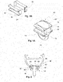
- Fig. 1A shows the guide element 10 having a body 12 with outwardly extending wings defining recesses 14 for cooperation with edges of a slot provided in a guide track (not shown).
- the body 12 of each guide element 10 has a depending eye 16 for receiving a curtain hook (not shown).
- the guide elements 10 may be molded in one piece so as to have upper and lower horizontal walls 18, 20 respectively of which the wings constitute extensions, joined by forward and rear vertical walls 22.
- upper and lower refer to orientations with the guide elements supported by the track arranged in horizontally orientation.
- the opposing faces of the wing extensions of the upper and the lower walls 18, 20 which define recesses 14 are preferably slightly convex. Therefore, the spacing between the front and the rear vertical walls 22 of the guide element 10 increase to simplify the insertion of such a guide element 10 into the track and travel along.
- the portion of the body 12 of the guide element which defines the eye 16 extends downwardly from the lower horizontal wall 20, the underside of which is channeled so that the eye 16 has a partly circular profile. Oher profiles for the eye 16 are possible, like rectangular etc.
- an insert 30 made of a silencing material is seen.
- the insert 30 can be received into one of the recesses 14 formed between the opposing faces of the wing extensions of the upper and lower walls 18, 20.
- This insert 30 is provided with a linear sliding surface 32 projecting laterally from a vertical wall 34 and extending throughout the length of the insert 30.
- the sliding surface 32 can be seen as a bearing surface.
- the sliding surface 32 is convex in shape as the shape of the recesses 14 of the guide element 10.
- the insert With the slightly convex shape of the opposing faces of the wing extensions of the upper and lower walls 18, 20 of the guide element 10 the insert can be secured in position. Furthermore, at the forward and/or rear vertical walls 22 of the body 12 an end part of the upper and lower walls 18, 20 i.e. the wing extensions can be formed such that the spacing between them is slightly reduced to provide a certain barrier to hold the insert in position.
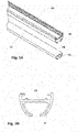
- a system for suspension of a curtain device comprising a tubular guide track 40 made of metal, for example aluminum alloy, or plastic material having a longitudinal extending slot 42 in its underside, defined by two opposed flanges 44 projecting from the side walls 46, wherein the parts 48 of the flanges 44 providing a bearing surface 50 for the guide element 10.
- the parts 48 can be formed as to slope towards the slot 42, for example the parts 44 can form segments of a circle.
- the slot 42 is at least as wide as the width of the clearance of the guide element 10, therefore the parts 48 of the flanges 44 are received into the recesses 14 of the guide element 10.
- the sliding surface 32, providing a bearing surface of the guide element 10 is adapted to engage with the bearing surface 50 of the guide track 40.
- Fig. 3A shows a tubular guide track 40 made of metal, for example aluminum alloy, or plastic material. Furthermore, it is shown an insert 41 formed to fit into the recess limited by the two opposed flanges 44 projecting from the side walls 46 of the guide track 40.
- the insert 41 can be made of any suitable silencing material.
- the insert 41 can be bonded in any appropriate way to the side walls 46 and the flanges 44 providing the bearing surface 50. Referring to fig. 3B the insert 41 is accommodated into the recess formed by the parts of the guide track 40 and bonded thereto.
- a guide element 10 not according to the invention is shown for illustration purposes only, wherein the guide element 10 is formed to correspond to an inversed T-shape guide track 40.
- the cross-section of the guide track 40 comprises a generally upright vertical wall 52 and a perpendicular base flange 54.
- the body of the guide element 10 is formed to provide a rectangular recess 14 partly opened, wherein the flange 54 of T-shape guide track 40 can be accommodated.
- the guide element 10 comprises the sliding surface 32 adapted to engage with bearing surfaces 50 of the basis flange 54 of the guide track 40.
- the sliding surface 32 can be provided by a coating of the walls of the recess 14 of the guide element 10 which are in contact with the bearing surface 50 of the guide track 40.
- bearing surfaces 50 can be coated wherein the coating can be achieved by dipping in or spraying or brushing with liquid thermoplastic on at least roller or glider tracks and on the surfaces against which faces of rollers or gliders will engage.
- bearing surfaces 50 for example of aluminum tracks can be impregnated with silicon fluid.
- the guide element 10 not according to the invention and present for illustration purposes only is formed as a cylindrical body 56 with a portion 58 of the body extending downwardly from a lower end of the cylindrical body 56 wherein in this downwardly extending portion 58 a ring 60 can be provided to receive a curtain hook (not shown).
- parts 62 of the surface of the guide element 10 which are adapted to engage with parts of the guide track 40 (not shown) are coated by a silencing material 64.
- the guide element 10 can comprise more than one piece wherein the pieces can be attached to each other to form the guide element 10 shown in fig. 1A .
- the body 12 of the guide element 10 comprises the upper horizontal wall 18 with the wing extension and the lower horizontal wall 20 with wing extension and between the upper and the lower horizontal walls spaced apart a longitudinal extending element 66 of widely rectangular cross-section, joined together at one of the forward or rear vertical walls 22.
- the body 12 of the guide element 10 forms the recess 14 for receiving the insert 30.
- One front side of the body 12 is opened and is adapted to receive the insert 30 which is formed to fit into the formed recess 14.
- the opened front side of the body 12 of the guide element 10 can be closed with an end cap 68 shaped with a double T-shape comprising upper and lower horizontal walls 18, 20 with wing extensions.
- the end cap 68 can be fixedly attached to the body 12 of the guide element 10 through pins 70 provided on the end cap 68 which can be fitted into holes 72 provided at the opened front side of the body 12 of the guide element 10 or vice versa.
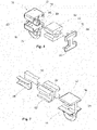
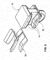
- Fig. 7 shows another embodiment of the invention.
- the guide element 10 comprises a body 12 according to the embodiment of fig. 1A , made of a rigid material like polyoxymethylen or polyamide or the like.
- the body 12 has the outwardly extending wings 18, 20 defining the recesses 14.
- the recesses 14 are designed to accommodate an insert 30 which is made of damping material like a rubber material showing a shore hardness of a softer plastic.
- the shore A hardness scale measures the hardness of flexible mold rubbers that range in hardness from very soft to hard and from flexible to almost no flexibility. Preferably the shore A hardness is selected properly.
- the insert 30 is provided for absorbing vibrations and noise caused by gliding of the guide element 10 along the guide track 40 (not shown).
- the insert 30 is bonded in appropriate way into the recesses 14 of the body 12 of the guide element 10.
- the insert 30 is formed with outwardly extending wings related to the wings 18, 20 of the body 12.
- the insert 30 shows slightly convex surfaces 82.
- Shown in fig. 7 elements 90 are made of a more rigid material.
- the elements 90 are formed to be inserted in the recesses each formed by the upper and lower outwardly extending wings of the insert 30.
- the elements 90 arranged in the recesses formed in the insert 30 provide the slightly convex shaped linear surfaces 32.
- the elements 90 are formed with small wall thickness. Therefore, when accommodated into the insert 30 the elements 90 forms a thin layer or a coating adapted to provide the sliding surface 32.
- the thin layer or coating shows excellent gliding properties wherein the insert 30 can absorb the vibration and the noise.
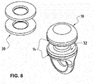
- Fig. 8 shows an alternative embodiment of the invention.
- the guide element 10 formed with a round body comprises recesses 14 formed as a notch wherein the inserts 30 are accommodated and secured respectively.
- the sliding surfaces 32 are provided by the guide element 10 and are made preferably of a more rigid material than the material of the insert 30.
- Fig. 9 shows an alternative embodiment of the invention.
- the guide element 10 is in a form similar to the embodiment of fig. 1A .
- the guide element 10 comprises recesses 14 formed as notches accommodating the inserts 30.
- the inserts 30 are made of another material as the guide element 10 which is made of a rigid material. According to this embodiment the sliding surfaces 32 are formed by the guide element 10.
Landscapes
- Curtains And Furnishings For Windows Or Doors (AREA)
- Bearings For Parts Moving Linearly (AREA)
Description
- The present invention relates to a system for suspension of a curtain device, comprising at least one curtain guide and at least one curtain or the like that is suspended on a plurality of suspension units with a guide element for guiding a suspension unit along the curtain guide.
- A known objection of systems for suspension of a curtain device is the noise caused by the movement of the suspension units along the curtain guide. Even if the noise is small, it can be disturbing. For example, in a hospital, in operating rooms, in theaters or cinemas or even in private space the noise of opening and closing a curtain device is undesirable.
- The curtain guide for guiding and/or supporting an object provides at least one guide rail or track. The curtain guide track can be an elongated profile element or can comprise curved sections. The curtain guide also described as guide track or rail or profile element can be of substantially circular, oval, rectangular or other cross-section with any reasonable size. The curtain guide comprises at least a guide track providing a bearing surface for slidably mounting the guide elements.
- Curtain guide tracks are known wherein at least one slot is formed in the guide track and open to the external surface of the guide track supporting a plurality of gliders or sliders or guide elements for movement along the guide track. For example, a known guide track can be formed with a hollow extruded track having an inside bearing surface wherein guide elements are moveably mounted for supporting a slidable curtain or the like and wherein the guide track opposite edges projecting from the side walls limit the width of the longitudinal track slot and an inner face forms sliding surfaces for internal guide elements, wherein said surfaces are inclined towards the track slot.
- Another example of a guide track has a cross-section including generally upright web having a perpendicular base flange on which the guide elements can ride.
- It is important to choose the profile of the mentioned bearing surfaces or sliding tracks of the guide track in such a manner and in conformity with the materials employed that a smooth and silent run of the guide elements is guaranteed. In case of guide tracks in form of extruded metallic shapes, especially aluminum alloy, the surface has to be finished to a "super-finish" quality in order to remove all grains from the extrusion skin which can be the source of further noise by movement of guide elements.
- A suspension unit used in the system comprises at least a suspension element to which a curtain device or the like can be secured and a guide element for guiding in or at the guide track. The suspension element is used to support a curtain hook which is fitted into a pocket in a heading tape secured to a curtain. The guide element, i.e. the component moveable along the guide track of a curtain guide, is formed to slide on or in the track provided by the guide track. Furthermore, a guide element is formed as a roller to travel along the guide track on wheels or rollers.
- To achieve a silent movement of guide elements moved along guide tracks different modifications are known. It is well-known that the guide element can be made of fiber, hard leather or other material which will serve the purpose and afford a minimum of friction and noise in use. But a guide element can be made also of synthetic plastic material, wherein it is formed with sliding surfaces convex in shape and wherein through the friction between the sliding surfaces of the guide track and the guide element a more durable wearing surface of the guide element is obtained to achieve noiseless movement thereof.
- Furthermore, it is known to make a guide element from a thin metal strip covered by a wrap of textile fiber, wherein the fabric can be woven, knitted or braided or felted. Known guide elements are made from metal wherein those parts of the guide element touching the guide rail may be faced or shod with an anti-friction material, i.e. the material can only cover essential parts of the guide elements.
- Furthermore, it is known to obtain guide elements providing a substantially silent movement within or at the guide track by providing at essentially contact surfaces silencing materials. Therefore, guide elements are known comprising a rigid body to which at one end a pair of rollers having tires formed of rubber or other deformable and preferably silencing material.
- Additionally, it is known to provide cushions which slidably engage parts of the guide track in a manner to limit lateral swinging and silencing engagement of the guide element with parts of the guide track during opening and closing of the curtains. The cushions can be arranged in recesses formed at the contact portions between guide track and guide element.
-
DE 11 39 950 B discloses a curtain rail and guide elements whereby contact surfaces between them are provided with inserts of a solid material with lubrication properties, poured or inserted in grooves made in the contact surfaces to provide a sliding surface. -
JP 2001 061642 A -
JP H07 34787 U -
JP H08 89393 A - However, there is still the problem of noise during movement of the guide elements along guide track caused by rolling or sliding friction.
- The object of the present invention is therefore to propose a system for suspension of a curtain device comprising a guide track and a slidably mounted guide element to reduce the noise of the movement of the guide elements along the guide track, i.e. to provide a smooth and silent movement which is almost noiseless.
- A further object is to propose a system for suspension of a curtain device which can be used with gliders formed to slide on the guide track as well as rollers adapted to roll on such track surfaces.
- A still further object is that the guide element can have different shapes and forms and can be made of plastic material as molding.
- The above mentioned objects are achieved by the features of the
independent claims 1, 2 and 3, according to which a system for suspension of a curtain device, comprising at least one curtain guide track and at least one curtain or the like that is suspended on a plurality of suspension units, wherein the suspension units each comprise a guide element for guiding a respective suspension unit along the curtain guide track, wherein the curtain guide track and the guide element each provide a bearing surface. The bearing surface of the guide track provides the sliding or rolling surface on which the guide element is moved by sliding or rolling along, wherein the guide element comprises a bearing surface providing engagement with the guide track, i.e. the bearing surface of the guide track. - In each applications of the invention those parts where the guide element touches the curtain guide track a silencing material is provided to reduce friction and noise. The silencing material, showing damping properties is formed as an insert received in recesses formed on the bearing surface of the guide element and/or the guide track which are made of a rigid material, wherein the insert is made of a softer material than the rigid material of the guide element and/or the guide track.
- The system is characterized in that a coating or a thin layer, each of a more rigid material than the material of the insert is provided on the sliding surfaces of the guide element and/or the guide track to improve the gliding properties. Alternatively, the system is characterized in that the guide element provides recesses formed as a notch substantially parallel to the sliding surfaces to accommodate the silencing material formed as an insert made of a softer material than the material of the guide element. According to the invention the expression bearing surface complies as well the bearing surface as at least partly a part adjacently to the bearing surface. The silencing material can be chosen from a group comprising fiber composites, synthetic materials, wood and textile. Application of silencing material at least on one of the bearing surfaces reduces significantly the noise caused by moving guide elements along guide tracks.
- The preferred silencing material is a fiber composite, mostly preferred felt. Herein the expression felt means a material made of matted and compressed fibers, pressed together using heat, moisture and/or pressure, wherein natural fibers such as wool or synthetic fibers such as polyamide, polyester etc. can be used. Felt is a material offering a wide versatility. Felt is an excellent sound insulator showing superb vibration damping properties. Felt is a vibration dampener mostly because its stress-deformation curve forms a hysterics loop, soaking most of the energy. Felt is highly resilient, retaining its strength and unique properties for a long time. Felt can be cut in any size, shape or thickness or can be heat formed and run through dies which will form it into shapes. Felt can be bonded to most surfaces.
- Furthermore, the silencing material may be impregnated with graphite, wax or other suitable lubricant. For example, felt can be impregnated because of its reservoir properties. Felt can absorb and hold several times of its weight in various fluids, including lubricants. The ability of transfer the lubricant as needed to bearing surfaces through the felt makes felt an ideal lubricator.
- According to prior art, a silencing material is provided as a coating on at least one of the bearing surfaces of either the guide track or the guide element or both of them. The coating can be build up by application of the silencing material on at least one of the bearing surfaces for example by spraying.
- According to one aspect, the silencing material as an insert can be attached to the bearing surfaces by adhesion, welding and/or injection-molding, furthermore by crimping, rolled -in.
- According to the invention, the silencing material is formed as an insert received in recesses formed on the bearing surfaces of the guide track and/or the guide element or both. The insert is made of a silencing material showing damping properties, wherein the insert is accommodated at the guide element made of a rigid material. According to one aspect, the silencing material formed as an insert is accommodated in a notch formed at the guide element, formed substantially parallel to the sliding surfaces. The insert is made of a softer material as the rigid material of the guide element wherein sliding surfaces are made of the rigid material.
- According to another aspect, the silencing material formed as an insert is accommodated such that the silencing material provides sliding surfaces. To improve the gliding properties a coating or a thin layer, each of a more rigid material is provided on the sliding surfaces of such an insert. In one embodiment the silencing material formed as an insert is attached by pressing into a recess provided at least on one of the bearing surfaces. According to one aspect, the recess is formed on the bearing surface of the guide element. The guide element can be of roller-type comprising a rigid body having an externally essentially cylindrical transverse portion within a transverse shaft is journaled. This shaft carries at its opposite ends a pair of rollers having wheels or rollers formed of another material than the rigid body. The material for the wheels may be a silencing material. In another embodiment of guide elements of roller-type the bearing surface of the wheels are provided with a recess to insert a silencing material in this recess.
- The guide element comprises a body providing a recess for receiving an insert made of the silencing material. The insert received in the recess can be secured by an end cap which is connectable to the body such as to hold the insert in position.
- The guide elements can be made of suitable plastic material, such as thermoplastic polymers as polypropylene, polyoxymethylen (acetal) or polyamide or compounding further comprising for example polytetrafluorethylene (PTFE). Furthermore, the guide element can be formed by two-component injection molding.
- In a preferred embodiment of the invention, the guide elements are formed as gliders for sliding along the guide track.
- Guide elements are retained by the track for sliding or rolling movement along it. The guide element can be suitable for internal and external sliding or rolling depending on the type of the track and the guide element.
- The invention will now be described by way of example with reference to the accompanying drawings in which
-
Fig. 1A is a schematic view of one embodiment of a guide element according to the invention; -
Fig. 1B is a schematic view of an insert for engagement with the guide element offig. 1A ; -
Fig. 2 is a schematic cross section view of guide element offig. 1 and a guide track; -
Fig. 3A, 3B are schematic views of one embodiment of a guide track according to the invention, wherein the guide track is combined with an insert; -
Fig. 4 is a schematic cross section view of a guide element in engagement with a guide track not according to the invention and is presented for illustration purposes only; -
Fig. 5 is a schematic cross section view of a guide element not according to the invention and is presented for illustration purposes only; -
Fig. 6 is a schematic view of an embodiment of a guide element according to the invention; -
Fig. 7 is a schematic view of an embodiment of a guide element according to the invention; -
Fig. 8 is a schematic view of another embodiment of a guide element according to the invention; -
Fig. 9 is a schematic view of another embodiment of a guide element according to the invention. - With reference to the above figures, the
general reference numeral 10 indicates a guide element.Fig. 1A shows theguide element 10 having abody 12 with outwardly extendingwings defining recesses 14 for cooperation with edges of a slot provided in a guide track (not shown). Thebody 12 of eachguide element 10 has a dependingeye 16 for receiving a curtain hook (not shown). - The
guide elements 10 may be molded in one piece so as to have upper and lowerhorizontal walls vertical walls 22. Herein the expressions of upper and lower refer to orientations with the guide elements supported by the track arranged in horizontally orientation. The opposing faces of the wing extensions of the upper and thelower walls vertical walls 22 of theguide element 10 increase to simplify the insertion of such aguide element 10 into the track and travel along. The portion of thebody 12 of the guide element which defines theeye 16 extends downwardly from the lowerhorizontal wall 20, the underside of which is channeled so that theeye 16 has a partly circular profile. Oher profiles for theeye 16 are possible, like rectangular etc. - In
fig. 1B aninsert 30 made of a silencing material is seen. Theinsert 30 can be received into one of therecesses 14 formed between the opposing faces of the wing extensions of the upper andlower walls insert 30 is provided with a linear slidingsurface 32 projecting laterally from avertical wall 34 and extending throughout the length of theinsert 30. The slidingsurface 32 can be seen as a bearing surface. The slidingsurface 32 is convex in shape as the shape of therecesses 14 of theguide element 10. - With the slightly convex shape of the opposing faces of the wing extensions of the upper and
lower walls guide element 10 the insert can be secured in position. Furthermore, at the forward and/or rearvertical walls 22 of thebody 12 an end part of the upper andlower walls - Referring to
fig. 2 a system for suspension of a curtain device is shown, comprising atubular guide track 40 made of metal, for example aluminum alloy, or plastic material having a longitudinal extendingslot 42 in its underside, defined by twoopposed flanges 44 projecting from theside walls 46, wherein theparts 48 of theflanges 44 providing a bearingsurface 50 for theguide element 10. Theparts 48 can be formed as to slope towards theslot 42, for example theparts 44 can form segments of a circle. Theslot 42 is at least as wide as the width of the clearance of theguide element 10, therefore theparts 48 of theflanges 44 are received into therecesses 14 of theguide element 10. The slidingsurface 32, providing a bearing surface of theguide element 10 is adapted to engage with the bearingsurface 50 of theguide track 40. -
Fig. 3A shows atubular guide track 40 made of metal, for example aluminum alloy, or plastic material. Furthermore, it is shown aninsert 41 formed to fit into the recess limited by the twoopposed flanges 44 projecting from theside walls 46 of theguide track 40. Theinsert 41 can be made of any suitable silencing material. Theinsert 41 can be bonded in any appropriate way to theside walls 46 and theflanges 44 providing the bearingsurface 50. Referring tofig. 3B theinsert 41 is accommodated into the recess formed by the parts of theguide track 40 and bonded thereto. - Referring to
fig. 4 , aguide element 10 not according to the invention is shown for illustration purposes only, wherein theguide element 10 is formed to correspond to an inversed T-shape guide track 40. The cross-section of theguide track 40 comprises a generally uprightvertical wall 52 and aperpendicular base flange 54. The body of theguide element 10 is formed to provide arectangular recess 14 partly opened, wherein theflange 54 of T-shape guide track 40 can be accommodated. Theguide element 10 comprises the slidingsurface 32 adapted to engage with bearingsurfaces 50 of thebasis flange 54 of theguide track 40. The slidingsurface 32 can be provided by a coating of the walls of therecess 14 of theguide element 10 which are in contact with the bearingsurface 50 of theguide track 40. Furthermore, the bearing surfaces 50 can be coated wherein the coating can be achieved by dipping in or spraying or brushing with liquid thermoplastic on at least roller or glider tracks and on the surfaces against which faces of rollers or gliders will engage. In addition, bearing surfaces 50 for example of aluminum tracks can be impregnated with silicon fluid. - In
fig. 5 theguide element 10 not according to the invention and present for illustration purposes only is formed as acylindrical body 56 with aportion 58 of the body extending downwardly from a lower end of thecylindrical body 56 wherein in this downwardly extending portion 58 aring 60 can be provided to receive a curtain hook (not shown). As can be seen fromfig. 5 ,parts 62 of the surface of theguide element 10 which are adapted to engage with parts of the guide track 40 (not shown) are coated by a silencingmaterial 64. - In another embodiment of the invention, shown in
fig. 6 , theguide element 10 can comprise more than one piece wherein the pieces can be attached to each other to form theguide element 10 shown infig. 1A . According to this embodiment, thebody 12 of theguide element 10 comprises the upperhorizontal wall 18 with the wing extension and the lowerhorizontal wall 20 with wing extension and between the upper and the lower horizontal walls spaced apart a longitudinal extendingelement 66 of widely rectangular cross-section, joined together at one of the forward or rearvertical walls 22. Thebody 12 of theguide element 10 forms therecess 14 for receiving theinsert 30. One front side of thebody 12 is opened and is adapted to receive theinsert 30 which is formed to fit into the formedrecess 14. The opened front side of thebody 12 of theguide element 10 can be closed with anend cap 68 shaped with a double T-shape comprising upper and lowerhorizontal walls end cap 68 can be fixedly attached to thebody 12 of theguide element 10 throughpins 70 provided on theend cap 68 which can be fitted intoholes 72 provided at the opened front side of thebody 12 of theguide element 10 or vice versa. -
Fig. 7 shows another embodiment of the invention. Theguide element 10 comprises abody 12 according to the embodiment offig. 1A , made of a rigid material like polyoxymethylen or polyamide or the like. Thebody 12 has the outwardly extendingwings recesses 14. Therecesses 14 are designed to accommodate aninsert 30 which is made of damping material like a rubber material showing a shore hardness of a softer plastic. The shore A hardness scale measures the hardness of flexible mold rubbers that range in hardness from very soft to hard and from flexible to almost no flexibility. Preferably the shore A hardness is selected properly. Theinsert 30 is provided for absorbing vibrations and noise caused by gliding of theguide element 10 along the guide track 40 (not shown). Theinsert 30 is bonded in appropriate way into therecesses 14 of thebody 12 of theguide element 10. Theinsert 30 is formed with outwardly extending wings related to thewings body 12. Furthermore, theinsert 30 shows slightly convex surfaces 82. Shown infig. 7 elements 90 are made of a more rigid material. Theelements 90 are formed to be inserted in the recesses each formed by the upper and lower outwardly extending wings of theinsert 30. Theelements 90 arranged in the recesses formed in theinsert 30 provide the slightly convex shaped linear surfaces 32. Theelements 90 are formed with small wall thickness. Therefore, when accommodated into theinsert 30 theelements 90 forms a thin layer or a coating adapted to provide the slidingsurface 32. The thin layer or coating shows excellent gliding properties wherein theinsert 30 can absorb the vibration and the noise. -
Fig. 8 shows an alternative embodiment of the invention. Theguide element 10 formed with a round body comprises recesses 14 formed as a notch wherein theinserts 30 are accommodated and secured respectively. The sliding surfaces 32 are provided by theguide element 10 and are made preferably of a more rigid material than the material of theinsert 30. -
Fig. 9 shows an alternative embodiment of the invention. Theguide element 10 is in a form similar to the embodiment offig. 1A . Theguide element 10 comprisesrecesses 14 formed as notches accommodating theinserts 30. Theinserts 30 are made of another material as theguide element 10 which is made of a rigid material. According to this embodiment the slidingsurfaces 32 are formed by theguide element 10.
Claims (12)
- A system for suspension of a curtain device, the system comprising at least one curtain guide track (40) and at least one curtain that is suspended on a plurality of suspension units, wherein the suspension units each comprise a guide element (10) for guiding a respective suspension unit along the curtain guide track (40),wherein the curtain guide track (40) and the guide element (10) each provide a bearing surface (50),wherein a silencing material (64) showing damping properties is formed as an insert (30) received in recesses (14) formed on the bearing surface (50) of the guide element (10) which is made of a rigid material,wherein the insert (30) is made of a softer material than the rigid material of the guide element (10), andwherein the silencing material (64) provides sliding surfaces (32)characterized in thata coating or a thin layer, each of a more rigid material than the material of the insert (30) is provided on the sliding surfaces (32) to improve the gliding properties.
- A system for suspension of a curtain device, the system comprising at least one curtain guide track (40) and at least one curtain that is suspended on a plurality of suspension units, wherein the suspension units each comprise a guide element (10) for guiding a respective suspension unit along the curtain guide track (40),wherein the curtain guide track (40) and the guide element (10) each provide a bearing surface (50),wherein a silencing material (64) showing damping properties is formed as an insert (30) received in recesses (14) formed in the body (12) of the guide element (10) which is made of a rigid material,wherein the insert (30) is made of a softer material than the rigid material of the guide element (10)characterized in thatsliding surfaces (32) are provided by the guide element (10),wherein the recesses (14) are formed as a notch substantially parallel to the sliding surfaces (32).
- A system for suspension of a curtain device, the system comprising at least one curtain guide track (40) and at least one curtain that is suspended on a plurality of suspension units, wherein the suspension units each comprise a guide element (10) for guiding a respective suspension unit along the curtain guide track (40),wherein the curtain guide track (40) and the guide element (10) each provide a bearing surface (50),wherein a silencing material (64) showing damping properties is formed as an insert (41) received in recesses (14) formed on the bearing surface (50) of the guide track (40) which is made of a rigid material,wherein the insert (41) is made of a softer material than the rigid material of the guide track (40), andwherein the silencing material (64) provides sliding surfaces (32)characterized in thata coating or a thin layer, each of a more rigid material than the material of the insert (41) is provided on the sliding surfaces (32) to improve the gliding properties.
- A system for suspension of a curtain device according to claim 1 , characterized in thata silencing material (64) showing damping properties is formed as a further insert (41) received in recesses (14) formed on the bearing surface (50) of the guide track (40), wherein the guide track (40) is made of a rigid material,the further insert (41) of the guide track (40) is made of a softer material than the rigid material of the guide track (40),wherein the silencing material (64) of both inserts (30; 41) provides sliding surfaces (32), anda coating or a thin layer, each of a more rigid material than the material of the inserts (30; 41) is provided on the sliding surfaces (32) to improve the gliding properties.
- A system for suspension of a curtain device according to claim 2,characterized in thata silencing material (64) showing damping properties is formed as a further insert (41) received in recesses (14) formed on the bearing surface (50) of the guide track (40),wherein the guide track (40) is made of a rigid material,wherein the further insert (41) of the guide track (40) is made of a softer material than the rigid material of the guide track (40), andwherein the further sliding surfaces (32) of the guide track (40) are provided by a coating or a thin layer, each of a more rigid material than the further insert (41) of the guide track (40) to improve the gliding properties.
- A system for suspension of a curtain device according to one of the proceeding claims, wherein the silencing material (64) is made of fiber composites, synthetic materials, wood, textile.
- A system for suspension of a curtain device according to claim 6, wherein the silencing material (64) is felt.
- A system for suspension of a curtain device according to one of the proceeding claims when depending on claims 1 and 3, wherein the silencing material (64) is attached to at least one of the bearing surfaces (50) by adhesion, welding, injection-molding, crimping and/or roll-in.
- A system for suspension of a curtain device according to claim 1, 3 or 4, wherein an element (90) formed as a thin layer of a more rigid material than the insert (30; 41) is bonded to the respective insert (30; 41) providing the sliding surfaces (32).
- A system for suspension of a curtain device according to claim 1, wherein the guide element (10) comprises a body (12) providing the recess (14) for receiving the insert (30) and an end cap (68) which is connectable to the body (12) to secure the insert (30) in the recess (14).
- A system for suspension of a curtain device according to claim 1 or 2, wherein the guide element (10) is formed as a glider for sliding along the curtain guide track (40).
- A system for suspension of a curtain device according to claim 1, wherein the guide element (10) is a roller for rolling along the curtain guide track (40).
Applications Claiming Priority (2)
| Application Number | Priority Date | Filing Date | Title |
|---|---|---|---|
| CH17002016 | 2016-12-21 | ||
| PCT/EP2017/082991 WO2018114650A1 (en) | 2016-12-21 | 2017-12-15 | System for suspension of a curtain |
Publications (2)
| Publication Number | Publication Date |
|---|---|
| EP3558068A1 EP3558068A1 (en) | 2019-10-30 |
| EP3558068B1 true EP3558068B1 (en) | 2022-09-07 |
Family
ID=58632104
Family Applications (1)
| Application Number | Title | Priority Date | Filing Date |
|---|---|---|---|
| EP17818116.0A Active EP3558068B1 (en) | 2016-12-21 | 2017-12-15 | System for suspension of a curtain |
Country Status (8)
| Country | Link |
|---|---|
| US (1) | US10806288B2 (en) |
| EP (1) | EP3558068B1 (en) |
| JP (1) | JP2020501710A (en) |
| CN (1) | CN110087514B (en) |
| AU (1) | AU2017380895B2 (en) |
| DK (1) | DK3558068T3 (en) |
| ES (1) | ES2929387T3 (en) |
| WO (1) | WO2018114650A1 (en) |
Families Citing this family (2)
| Publication number | Priority date | Publication date | Assignee | Title |
|---|---|---|---|---|
| US11547233B2 (en) * | 2020-02-07 | 2023-01-10 | The Boeing Company | Quick loading curtain track for an aircraft cabin |
| US20220402609A1 (en) * | 2021-06-21 | 2022-12-22 | B/E Aerospace, Inc. | Carriage assembly with overload protection |
Family Cites Families (39)
| Publication number | Priority date | Publication date | Assignee | Title |
|---|---|---|---|---|
| US2966695A (en) * | 1957-07-15 | 1961-01-03 | James E Dwyer | Unitized severable drapery carriers |
| DE1139950B (en) * | 1960-12-21 | 1962-11-22 | Rudolf Stoerzbach | Curtain track with rolling or sliding hangers |
| US3187370A (en) * | 1961-11-22 | 1965-06-08 | Bruce J Bieda | Drapery hanger |
| US3342344A (en) * | 1966-07-15 | 1967-09-19 | Vogel Peterson Co | Hanger receptacle and garment suspension apparatus employing the same |
| US4356902A (en) * | 1977-10-17 | 1982-11-02 | Murphy Raymond J | Bearing and support |
| US4282630A (en) * | 1979-08-23 | 1981-08-11 | Toder Ellis I | Drapery carrier assembly |
| JP2821915B2 (en) * | 1989-10-11 | 1998-11-05 | トーソー株式会社 | Silent curtain device |
| US5259520A (en) * | 1992-02-26 | 1993-11-09 | Zenith Products Corp. | Curtain rod assembly and cover |
| NL9200489A (en) * | 1992-03-16 | 1993-10-18 | Bosgoed Groothandel B V | Curtain-hanging system, curtain-hanging component which can be fitted into this system, rail suitable for the system and method for bending the rail |
| NL9201903A (en) * | 1992-11-02 | 1994-06-01 | Forest Group Nederland Bv | Curtain rail and method for its manufacture. |
| US5421059A (en) * | 1993-05-24 | 1995-06-06 | Leffers, Jr.; Murray J. | Traverse support rod |
| JPH0734787U (en) * | 1993-12-20 | 1995-06-27 | トーソー株式会社 | Metal silent curtain rail |
| JPH0889393A (en) * | 1994-09-21 | 1996-04-09 | Toso Co Ltd | Silent metallic curtain rail |
| JPH09291747A (en) * | 1996-04-26 | 1997-11-11 | K G Partek Kk | Rail for sash roller |
| CA2223852C (en) * | 1997-12-05 | 2004-01-20 | George Albert Neil | Track and hook arrangement for storing a variety of articles |
| JP2001061642A (en) * | 1999-08-26 | 2001-03-13 | Sanshin Kogyo Kk | Curtain guide rail and its runner |
| CN2794374Y (en) * | 2005-01-28 | 2006-07-12 | 罗立津 | Noise silencing curtain rod |
| FR2884125B1 (en) * | 2005-04-12 | 2007-05-18 | Ykk France Sarl | CURTAIN ROD |
| US20070277944A1 (en) * | 2006-05-31 | 2007-12-06 | Hans Wu | Curtain track assembly |
| CN2902097Y (en) * | 2006-06-20 | 2007-05-23 | 广东创明遮阳科技有限公司 | Silence curtain device |
| US20150173549A1 (en) * | 2006-12-13 | 2015-06-25 | David Zahner | Track and Curtain System |
| GB2458075B (en) * | 2006-12-13 | 2011-07-06 | John Dewees | Track and curtain system |
| US20080148526A1 (en) * | 2006-12-22 | 2008-06-26 | Robert Stephen Garcia | Drapery rod |
| GB0820632D0 (en) * | 2008-11-12 | 2008-12-17 | Seddon Ivor H | Drapery hardware |
| US20100294441A1 (en) * | 2009-05-20 | 2010-11-25 | Merlin Manufacturing, Inc. | Method and apparatus for curtain baton with positionable pin |
| DE202009010880U1 (en) * | 2009-08-13 | 2009-12-24 | Stehr, Werner | Curtain rail with glides |
| CH702648B1 (en) * | 2010-02-03 | 2014-08-29 | Casatex Gmbh | Curtain glider as a sliding element for curtain rails. |
| US20120018106A1 (en) * | 2010-07-26 | 2012-01-26 | Susana Robledo | Disposable hospital curtain system with sliding curtain carriers for snap-in installation on existing ceiling tracks |
| US8316508B2 (en) * | 2011-02-03 | 2012-11-27 | Economy Tent International, Inc. | Removable track system and method for tent sidewalls |
| NL2007580C2 (en) * | 2011-10-12 | 2013-04-15 | Thomas Regout B V | CURTAIN RUNNER WITH CONTACT ELEMENTS AND A COMPOSITION OF A CURTAIN RAIL AND SUCH CURTAIN RUNNER. |
| CN203341489U (en) * | 2012-03-08 | 2013-12-18 | 简约帘幕有限公司 | Curtain supporting component |
| CN202874926U (en) * | 2012-10-22 | 2013-04-17 | 浙江德裕科技有限公司 | Aluminum alloy track capable of being curved and machined according to site demand |
| DE102013213996B4 (en) * | 2013-07-17 | 2019-11-07 | Siemens Healthcare Gmbh | C-arm bearing device and X-ray imaging device with a cage guide |
| CN203789658U (en) * | 2014-02-27 | 2014-08-27 | 雅霖工业股份有限公司 | Hanging sliding base structure |
| CN204071634U (en) * | 2014-07-24 | 2015-01-07 | 南通中皋铝制品有限公司 | Curtain connecting-type track |
| JP6423258B2 (en) * | 2014-12-12 | 2018-11-14 | 株式会社スガモトテント | Rail runner running structure |
| CN204708563U (en) * | 2015-06-26 | 2015-10-21 | 绍兴县布之道纺织品有限公司 | Curtain rail |
| US9700170B1 (en) * | 2015-12-30 | 2017-07-11 | Richard Kouts | Roller bearing system |
| CN106108583B (en) * | 2016-08-05 | 2019-09-17 | 宁波杜亚机电技术有限公司 | A kind of hanging wheel and application have the curtain rail of the hanging wheel |
-
2017
- 2017-12-15 DK DK17818116.0T patent/DK3558068T3/en active
- 2017-12-15 ES ES17818116T patent/ES2929387T3/en active Active
- 2017-12-15 CN CN201780078890.XA patent/CN110087514B/en active Active
- 2017-12-15 AU AU2017380895A patent/AU2017380895B2/en active Active
- 2017-12-15 US US16/462,008 patent/US10806288B2/en active Active
- 2017-12-15 JP JP2019531959A patent/JP2020501710A/en active Pending
- 2017-12-15 WO PCT/EP2017/082991 patent/WO2018114650A1/en unknown
- 2017-12-15 EP EP17818116.0A patent/EP3558068B1/en active Active
Also Published As
| Publication number | Publication date |
|---|---|
| ES2929387T3 (en) | 2022-11-28 |
| EP3558068A1 (en) | 2019-10-30 |
| US10806288B2 (en) | 2020-10-20 |
| DK3558068T3 (en) | 2022-10-03 |
| US20190328166A1 (en) | 2019-10-31 |
| AU2017380895B2 (en) | 2023-02-16 |
| CN110087514B (en) | 2021-12-28 |
| CN110087514A (en) | 2019-08-02 |
| JP2020501710A (en) | 2020-01-23 |
| AU2017380895A1 (en) | 2019-05-30 |
| WO2018114650A1 (en) | 2018-06-28 |
Similar Documents
| Publication | Publication Date | Title |
|---|---|---|
| EP3558068B1 (en) | System for suspension of a curtain | |
| CA1307687C (en) | Handrail for transportation apparatus | |
| JP2009504218A (en) | Improvement of slide support or improvement regarding slide support | |
| EP2761197B1 (en) | Re-circulating ball sliding support assembly | |
| JP2006071094A5 (en) | ||
| US20190039535A1 (en) | Vehicle interior panel with compressible layer of non-uniform thickness | |
| US20170122371A1 (en) | Re-circulating ball sliding support assembly | |
| CN105034861A (en) | Vehicle seat with roller guide | |
| US20170231413A1 (en) | Suspension Unit for a Curtain Device | |
| BR102013000717A2 (en) | Vehicle seat and use of a corrugated slide rod element | |
| US20190106919A1 (en) | Garage door noise reduction roller assembly with noise reduction roller wheel | |
| JP2011520728A (en) | Handrail for escalator or moving walkway | |
| CN201047397Y (en) | Circulation and rotatable type guide structure of linear sliding rail | |
| CN211474684U (en) | Bearing with good lubricating property | |
| CA2723566C (en) | Person conveying device, particularly escalator or moving walkway, with a handrail, and handrail for an escalator or a moving walkway | |
| US10816037B2 (en) | Seals for linear guides | |
| US20200370596A1 (en) | Telescopic rail | |
| CN216060127U (en) | Telescopic device for curtain rail | |
| JP2001065565A (en) | Rolling element connector and guiding device using it | |
| US20210244183A1 (en) | Arrangement for guiding at least one movable furniture part | |
| JP2017032058A5 (en) | ||
| JP2022541933A (en) | Traveling carriage for drawer guide | |
| TWI812202B (en) | Linear slide and self-lubricating structure thereof | |
| KR101654926B1 (en) | Sliding Load Reduction System for Sliding Door | |
| US2649297A (en) | Leaf spring assembly |
Legal Events
| Date | Code | Title | Description |
|---|---|---|---|
| STAA | Information on the status of an ep patent application or granted ep patent |
Free format text: STATUS: UNKNOWN |
|
| STAA | Information on the status of an ep patent application or granted ep patent |
Free format text: STATUS: THE INTERNATIONAL PUBLICATION HAS BEEN MADE |
|
| PUAI | Public reference made under article 153(3) epc to a published international application that has entered the european phase |
Free format text: ORIGINAL CODE: 0009012 |
|
| STAA | Information on the status of an ep patent application or granted ep patent |
Free format text: STATUS: REQUEST FOR EXAMINATION WAS MADE |
|
| 17P | Request for examination filed |
Effective date: 20190614 |
|
| AK | Designated contracting states |
Kind code of ref document: A1 Designated state(s): AL AT BE BG CH CY CZ DE DK EE ES FI FR GB GR HR HU IE IS IT LI LT LU LV MC MK MT NL NO PL PT RO RS SE SI SK SM TR |
|
| AX | Request for extension of the european patent |
Extension state: BA ME |
|
| DAV | Request for validation of the european patent (deleted) | ||
| DAX | Request for extension of the european patent (deleted) | ||
| STAA | Information on the status of an ep patent application or granted ep patent |
Free format text: STATUS: EXAMINATION IS IN PROGRESS |
|
| STAA | Information on the status of an ep patent application or granted ep patent |
Free format text: STATUS: EXAMINATION IS IN PROGRESS |
|
| 17Q | First examination report despatched |
Effective date: 20201009 |
|
| STAA | Information on the status of an ep patent application or granted ep patent |
Free format text: STATUS: EXAMINATION IS IN PROGRESS |
|
| GRAP | Despatch of communication of intention to grant a patent |
Free format text: ORIGINAL CODE: EPIDOSNIGR1 |
|
| STAA | Information on the status of an ep patent application or granted ep patent |
Free format text: STATUS: GRANT OF PATENT IS INTENDED |
|
| INTG | Intention to grant announced |
Effective date: 20220405 |
|
| GRAS | Grant fee paid |
Free format text: ORIGINAL CODE: EPIDOSNIGR3 |
|
| GRAA | (expected) grant |
Free format text: ORIGINAL CODE: 0009210 |
|
| STAA | Information on the status of an ep patent application or granted ep patent |
Free format text: STATUS: THE PATENT HAS BEEN GRANTED |
|
| RAP3 | Party data changed (applicant data changed or rights of an application transferred) |
Owner name: SILENT GLISS INTERNATIONAL AG |
|
| AK | Designated contracting states |
Kind code of ref document: B1 Designated state(s): AL AT BE BG CH CY CZ DE DK EE ES FI FR GB GR HR HU IE IS IT LI LT LU LV MC MK MT NL NO PL PT RO RS SE SI SK SM TR |
|
| REG | Reference to a national code |
Ref country code: GB Ref legal event code: FG4D |
|
| REG | Reference to a national code |
Ref country code: CH Ref legal event code: EP Ref country code: AT Ref legal event code: REF Ref document number: 1516359 Country of ref document: AT Kind code of ref document: T Effective date: 20220915 |
|
| REG | Reference to a national code |
Ref country code: DE Ref legal event code: R096 Ref document number: 602017061586 Country of ref document: DE |
|
| REG | Reference to a national code |
Ref country code: IE Ref legal event code: FG4D |
|
| REG | Reference to a national code |
Ref country code: DK Ref legal event code: T3 Effective date: 20220928 |
|
| REG | Reference to a national code |
Ref country code: FI Ref legal event code: FGE |
|
| REG | Reference to a national code |
Ref country code: SE Ref legal event code: TRGR |
|
| REG | Reference to a national code |
Ref country code: NL Ref legal event code: FP |
|
| REG | Reference to a national code |
Ref country code: NO Ref legal event code: T2 Effective date: 20220907 |
|
| REG | Reference to a national code |
Ref country code: ES Ref legal event code: FG2A Ref document number: 2929387 Country of ref document: ES Kind code of ref document: T3 Effective date: 20221128 |
|
| REG | Reference to a national code |
Ref country code: LT Ref legal event code: MG9D |
|
| PG25 | Lapsed in a contracting state [announced via postgrant information from national office to epo] |
Ref country code: RS Free format text: LAPSE BECAUSE OF FAILURE TO SUBMIT A TRANSLATION OF THE DESCRIPTION OR TO PAY THE FEE WITHIN THE PRESCRIBED TIME-LIMIT Effective date: 20220907 Ref country code: LV Free format text: LAPSE BECAUSE OF FAILURE TO SUBMIT A TRANSLATION OF THE DESCRIPTION OR TO PAY THE FEE WITHIN THE PRESCRIBED TIME-LIMIT Effective date: 20220907 Ref country code: LT Free format text: LAPSE BECAUSE OF FAILURE TO SUBMIT A TRANSLATION OF THE DESCRIPTION OR TO PAY THE FEE WITHIN THE PRESCRIBED TIME-LIMIT Effective date: 20220907 |
|
| PG25 | Lapsed in a contracting state [announced via postgrant information from national office to epo] |
Ref country code: HR Free format text: LAPSE BECAUSE OF FAILURE TO SUBMIT A TRANSLATION OF THE DESCRIPTION OR TO PAY THE FEE WITHIN THE PRESCRIBED TIME-LIMIT Effective date: 20220907 Ref country code: GR Free format text: LAPSE BECAUSE OF FAILURE TO SUBMIT A TRANSLATION OF THE DESCRIPTION OR TO PAY THE FEE WITHIN THE PRESCRIBED TIME-LIMIT Effective date: 20221208 |
|
| PG25 | Lapsed in a contracting state [announced via postgrant information from national office to epo] |
Ref country code: SM Free format text: LAPSE BECAUSE OF FAILURE TO SUBMIT A TRANSLATION OF THE DESCRIPTION OR TO PAY THE FEE WITHIN THE PRESCRIBED TIME-LIMIT Effective date: 20220907 Ref country code: RO Free format text: LAPSE BECAUSE OF FAILURE TO SUBMIT A TRANSLATION OF THE DESCRIPTION OR TO PAY THE FEE WITHIN THE PRESCRIBED TIME-LIMIT Effective date: 20220907 Ref country code: PT Free format text: LAPSE BECAUSE OF FAILURE TO SUBMIT A TRANSLATION OF THE DESCRIPTION OR TO PAY THE FEE WITHIN THE PRESCRIBED TIME-LIMIT Effective date: 20230109 Ref country code: CZ Free format text: LAPSE BECAUSE OF FAILURE TO SUBMIT A TRANSLATION OF THE DESCRIPTION OR TO PAY THE FEE WITHIN THE PRESCRIBED TIME-LIMIT Effective date: 20220907 |
|
| PG25 | Lapsed in a contracting state [announced via postgrant information from national office to epo] |
Ref country code: SK Free format text: LAPSE BECAUSE OF FAILURE TO SUBMIT A TRANSLATION OF THE DESCRIPTION OR TO PAY THE FEE WITHIN THE PRESCRIBED TIME-LIMIT Effective date: 20220907 Ref country code: PL Free format text: LAPSE BECAUSE OF FAILURE TO SUBMIT A TRANSLATION OF THE DESCRIPTION OR TO PAY THE FEE WITHIN THE PRESCRIBED TIME-LIMIT Effective date: 20220907 Ref country code: IS Free format text: LAPSE BECAUSE OF FAILURE TO SUBMIT A TRANSLATION OF THE DESCRIPTION OR TO PAY THE FEE WITHIN THE PRESCRIBED TIME-LIMIT Effective date: 20230107 Ref country code: EE Free format text: LAPSE BECAUSE OF FAILURE TO SUBMIT A TRANSLATION OF THE DESCRIPTION OR TO PAY THE FEE WITHIN THE PRESCRIBED TIME-LIMIT Effective date: 20220907 |
|
| REG | Reference to a national code |
Ref country code: DE Ref legal event code: R097 Ref document number: 602017061586 Country of ref document: DE |
|
| PG25 | Lapsed in a contracting state [announced via postgrant information from national office to epo] |
Ref country code: AL Free format text: LAPSE BECAUSE OF FAILURE TO SUBMIT A TRANSLATION OF THE DESCRIPTION OR TO PAY THE FEE WITHIN THE PRESCRIBED TIME-LIMIT Effective date: 20220907 |
|
| PLBE | No opposition filed within time limit |
Free format text: ORIGINAL CODE: 0009261 |
|
| STAA | Information on the status of an ep patent application or granted ep patent |
Free format text: STATUS: NO OPPOSITION FILED WITHIN TIME LIMIT |
|
| REG | Reference to a national code |
Ref country code: AT Ref legal event code: UEP Ref document number: 1516359 Country of ref document: AT Kind code of ref document: T Effective date: 20220907 |
|
| 26N | No opposition filed |
Effective date: 20230608 |
|
| PG25 | Lapsed in a contracting state [announced via postgrant information from national office to epo] |
Ref country code: SI Free format text: LAPSE BECAUSE OF FAILURE TO SUBMIT A TRANSLATION OF THE DESCRIPTION OR TO PAY THE FEE WITHIN THE PRESCRIBED TIME-LIMIT Effective date: 20220907 Ref country code: LU Free format text: LAPSE BECAUSE OF NON-PAYMENT OF DUE FEES Effective date: 20221215 |
|
| PG25 | Lapsed in a contracting state [announced via postgrant information from national office to epo] |
Ref country code: IE Free format text: LAPSE BECAUSE OF NON-PAYMENT OF DUE FEES Effective date: 20221215 |
|
| PGFP | Annual fee paid to national office [announced via postgrant information from national office to epo] |
Ref country code: GB Payment date: 20231220 Year of fee payment: 7 |
|
| PGFP | Annual fee paid to national office [announced via postgrant information from national office to epo] |
Ref country code: SE Payment date: 20231220 Year of fee payment: 7 Ref country code: NO Payment date: 20231222 Year of fee payment: 7 Ref country code: NL Payment date: 20231220 Year of fee payment: 7 Ref country code: IT Payment date: 20231221 Year of fee payment: 7 Ref country code: FR Payment date: 20231222 Year of fee payment: 7 Ref country code: FI Payment date: 20231221 Year of fee payment: 7 Ref country code: DK Payment date: 20231227 Year of fee payment: 7 Ref country code: DE Payment date: 20231214 Year of fee payment: 7 Ref country code: AT Payment date: 20231221 Year of fee payment: 7 |
|
| PGFP | Annual fee paid to national office [announced via postgrant information from national office to epo] |
Ref country code: BE Payment date: 20231220 Year of fee payment: 7 |
|
| PG25 | Lapsed in a contracting state [announced via postgrant information from national office to epo] |
Ref country code: HU Free format text: LAPSE BECAUSE OF FAILURE TO SUBMIT A TRANSLATION OF THE DESCRIPTION OR TO PAY THE FEE WITHIN THE PRESCRIBED TIME-LIMIT; INVALID AB INITIO Effective date: 20171215 |
|
| PGFP | Annual fee paid to national office [announced via postgrant information from national office to epo] |
Ref country code: ES Payment date: 20240130 Year of fee payment: 7 |
|
| PG25 | Lapsed in a contracting state [announced via postgrant information from national office to epo] |
Ref country code: CY Free format text: LAPSE BECAUSE OF FAILURE TO SUBMIT A TRANSLATION OF THE DESCRIPTION OR TO PAY THE FEE WITHIN THE PRESCRIBED TIME-LIMIT Effective date: 20220907 |
|
| PGFP | Annual fee paid to national office [announced via postgrant information from national office to epo] |
Ref country code: CH Payment date: 20240101 Year of fee payment: 7 |
|
| PG25 | Lapsed in a contracting state [announced via postgrant information from national office to epo] |
Ref country code: MK Free format text: LAPSE BECAUSE OF FAILURE TO SUBMIT A TRANSLATION OF THE DESCRIPTION OR TO PAY THE FEE WITHIN THE PRESCRIBED TIME-LIMIT Effective date: 20220907 |
|
| PG25 | Lapsed in a contracting state [announced via postgrant information from national office to epo] |
Ref country code: MC Free format text: LAPSE BECAUSE OF FAILURE TO SUBMIT A TRANSLATION OF THE DESCRIPTION OR TO PAY THE FEE WITHIN THE PRESCRIBED TIME-LIMIT Effective date: 20220907 |
|
| PG25 | Lapsed in a contracting state [announced via postgrant information from national office to epo] |
Ref country code: MC Free format text: LAPSE BECAUSE OF FAILURE TO SUBMIT A TRANSLATION OF THE DESCRIPTION OR TO PAY THE FEE WITHIN THE PRESCRIBED TIME-LIMIT Effective date: 20220907 |
|
| PG25 | Lapsed in a contracting state [announced via postgrant information from national office to epo] |
Ref country code: BG Free format text: LAPSE BECAUSE OF FAILURE TO SUBMIT A TRANSLATION OF THE DESCRIPTION OR TO PAY THE FEE WITHIN THE PRESCRIBED TIME-LIMIT Effective date: 20220907 |