EP3557526B1 - Striated region detection device, striated region detection method, and program - Google Patents
Striated region detection device, striated region detection method, and program Download PDFInfo
- Publication number
- EP3557526B1 EP3557526B1 EP17880750.9A EP17880750A EP3557526B1 EP 3557526 B1 EP3557526 B1 EP 3557526B1 EP 17880750 A EP17880750 A EP 17880750A EP 3557526 B1 EP3557526 B1 EP 3557526B1
- Authority
- EP
- European Patent Office
- Prior art keywords
- filter
- streak
- region
- value
- image
- Prior art date
- Legal status (The legal status is an assumption and is not a legal conclusion. Google has not performed a legal analysis and makes no representation as to the accuracy of the status listed.)
- Active
Links
- 238000001514 detection method Methods 0.000 title claims description 11
- 230000004044 response Effects 0.000 claims description 72
- 238000012545 processing Methods 0.000 claims description 36
- 238000000034 method Methods 0.000 claims description 25
- 230000008859 change Effects 0.000 claims description 4
- 238000012935 Averaging Methods 0.000 claims 2
- 238000004590 computer program Methods 0.000 claims 1
- 238000007689 inspection Methods 0.000 description 30
- 238000011156 evaluation Methods 0.000 description 28
- 238000003384 imaging method Methods 0.000 description 17
- 230000007547 defect Effects 0.000 description 13
- 230000006870 function Effects 0.000 description 12
- 238000007796 conventional method Methods 0.000 description 10
- 230000010365 information processing Effects 0.000 description 6
- 238000012360 testing method Methods 0.000 description 5
- 239000003795 chemical substances by application Substances 0.000 description 4
- 239000011347 resin Substances 0.000 description 4
- 229920005989 resin Polymers 0.000 description 4
- 239000000853 adhesive Substances 0.000 description 3
- 230000001070 adhesive effect Effects 0.000 description 3
- 238000009792 diffusion process Methods 0.000 description 3
- 238000009826 distribution Methods 0.000 description 3
- 230000000694 effects Effects 0.000 description 3
- 238000001914 filtration Methods 0.000 description 3
- 239000004973 liquid crystal related substance Substances 0.000 description 3
- 230000002093 peripheral effect Effects 0.000 description 3
- 238000004364 calculation method Methods 0.000 description 2
- 238000012937 correction Methods 0.000 description 2
- 230000002950 deficient Effects 0.000 description 2
- 238000010586 diagram Methods 0.000 description 2
- 238000003708 edge detection Methods 0.000 description 2
- 239000000284 extract Substances 0.000 description 2
- 239000000463 material Substances 0.000 description 2
- 238000000465 moulding Methods 0.000 description 2
- 229920005668 polycarbonate resin Polymers 0.000 description 2
- 239000004431 polycarbonate resin Substances 0.000 description 2
- 230000008569 process Effects 0.000 description 2
- 230000001953 sensory effect Effects 0.000 description 2
- 238000003860 storage Methods 0.000 description 2
- GWEVSGVZZGPLCZ-UHFFFAOYSA-N Titan oxide Chemical compound O=[Ti]=O GWEVSGVZZGPLCZ-UHFFFAOYSA-N 0.000 description 1
- 239000002390 adhesive tape Substances 0.000 description 1
- 238000004458 analytical method Methods 0.000 description 1
- 238000013459 approach Methods 0.000 description 1
- 239000003086 colorant Substances 0.000 description 1
- 230000007613 environmental effect Effects 0.000 description 1
- 238000002474 experimental method Methods 0.000 description 1
- 239000011888 foil Substances 0.000 description 1
- 238000010191 image analysis Methods 0.000 description 1
- 238000004519 manufacturing process Methods 0.000 description 1
- 229910052751 metal Inorganic materials 0.000 description 1
- 239000002184 metal Substances 0.000 description 1
- 238000012986 modification Methods 0.000 description 1
- 230000004048 modification Effects 0.000 description 1
- 230000003287 optical effect Effects 0.000 description 1
- 229920003229 poly(methyl methacrylate) Polymers 0.000 description 1
- 239000004926 polymethyl methacrylate Substances 0.000 description 1
- 238000011002 quantification Methods 0.000 description 1
- OGIDPMRJRNCKJF-UHFFFAOYSA-N titanium oxide Inorganic materials [Ti]=O OGIDPMRJRNCKJF-UHFFFAOYSA-N 0.000 description 1
- 230000000007 visual effect Effects 0.000 description 1
Images


Classifications
-
- G—PHYSICS
- G06—COMPUTING; CALCULATING OR COUNTING
- G06T—IMAGE DATA PROCESSING OR GENERATION, IN GENERAL
- G06T7/00—Image analysis
- G06T7/40—Analysis of texture
-
- G—PHYSICS
- G06—COMPUTING; CALCULATING OR COUNTING
- G06T—IMAGE DATA PROCESSING OR GENERATION, IN GENERAL
- G06T7/00—Image analysis
- G06T7/10—Segmentation; Edge detection
- G06T7/11—Region-based segmentation
-
- G—PHYSICS
- G06—COMPUTING; CALCULATING OR COUNTING
- G06T—IMAGE DATA PROCESSING OR GENERATION, IN GENERAL
- G06T7/00—Image analysis
- G06T7/0002—Inspection of images, e.g. flaw detection
- G06T7/0004—Industrial image inspection
-
- G—PHYSICS
- G01—MEASURING; TESTING
- G01M—TESTING STATIC OR DYNAMIC BALANCE OF MACHINES OR STRUCTURES; TESTING OF STRUCTURES OR APPARATUS, NOT OTHERWISE PROVIDED FOR
- G01M11/00—Testing of optical apparatus; Testing structures by optical methods not otherwise provided for
-
- G—PHYSICS
- G06—COMPUTING; CALCULATING OR COUNTING
- G06T—IMAGE DATA PROCESSING OR GENERATION, IN GENERAL
- G06T1/00—General purpose image data processing
-
- G—PHYSICS
- G06—COMPUTING; CALCULATING OR COUNTING
- G06T—IMAGE DATA PROCESSING OR GENERATION, IN GENERAL
- G06T5/00—Image enhancement or restoration
- G06T5/20—Image enhancement or restoration by the use of local operators
-
- G—PHYSICS
- G06—COMPUTING; CALCULATING OR COUNTING
- G06T—IMAGE DATA PROCESSING OR GENERATION, IN GENERAL
- G06T7/00—Image analysis
-
- G—PHYSICS
- G06—COMPUTING; CALCULATING OR COUNTING
- G06T—IMAGE DATA PROCESSING OR GENERATION, IN GENERAL
- G06T7/00—Image analysis
- G06T7/10—Segmentation; Edge detection
- G06T7/12—Edge-based segmentation
-
- G—PHYSICS
- G06—COMPUTING; CALCULATING OR COUNTING
- G06T—IMAGE DATA PROCESSING OR GENERATION, IN GENERAL
- G06T7/00—Image analysis
- G06T7/60—Analysis of geometric attributes
-
- G—PHYSICS
- G06—COMPUTING; CALCULATING OR COUNTING
- G06T—IMAGE DATA PROCESSING OR GENERATION, IN GENERAL
- G06T2207/00—Indexing scheme for image analysis or image enhancement
- G06T2207/20—Special algorithmic details
- G06T2207/20024—Filtering details
-
- G—PHYSICS
- G06—COMPUTING; CALCULATING OR COUNTING
- G06T—IMAGE DATA PROCESSING OR GENERATION, IN GENERAL
- G06T2207/00—Indexing scheme for image analysis or image enhancement
- G06T2207/30—Subject of image; Context of image processing
- G06T2207/30108—Industrial image inspection
- G06T2207/30121—CRT, LCD or plasma display
Definitions
- the present invention relates to a technique for detecting a streak-like region in an image.
- An edge-lit type plane light source device is used as a backlight for a liquid crystal display device.
- the edge-lit type device includes light sources such as LEDs (Light Emitting Diodes) along an edge of the light-emitting surface of the plane light source device and is configured to guide light emitted from the light sources to the light-emitting surface by a plate-shaped light guide (called a light-guiding panel).
- the edge-lit type plane light source device can be relatively easily reduced in size/thickness and therefore has been widely used in small size electronic equipment such as a smart phone.
- An edge-lit plane light source device may be encountered with a failure related to luminance unevenness attributable to various causes such as a defect in a mold for a light-guiding panel or poor molding thereof and shifting during assembly.
- a failure is a bright or dark region appearing to linearly extend in a streak-like shape in one direction.
- the bright region has relatively high luminance with respect to the surrounding region, and the dark region has relatively low luminance with respect to the surrounding region.
- the failure of this kind will be referred to as a "streak-like region" or a "streak-like defect” .
- inspection of failures of this kind actually depends on visual sensory inspection carried out by a person (an inspector). Therefore, the inspection procedure may take time and trouble and can be costly or the results of the inspection depend much on personal skills, and there has been a demand for automation and objectification (quantification) of the inspection.
- JP 2005-346300A suggests a method for automatically inspecting for a streak-like defect at a display device such as a liquid crystal panel or a projector as an applied product thereof by image processing. According to the method, an image acquired by photographing a test object is scanned with a filter having a kernel in coincidence with the luminance variation pattern of a streak-like defect and the streak-like defect is detected.
- US 7 043 080 B1 discloses methods and systems for detection and delineation of text characters in images which may contain combinations of text and graphical content, more specifically intensity contrast edge detection methods and intensity gradient direction determination methods in conjunction with analyses of intensity curve geometry to determine the presence of text and verify text edge identification.
- US 2007/253596 A1 discloses an image processing apparatus, wherein a detection subject region setting unit obtains a picked-up image at a first time point as a standard image from time-series picked-up image data obtained by an image pickup unit and selects a plurality of correlation windows including an image region of the detection subject in the standard image with relative positions with respect to the standard point being identified.
- a movement detection unit obtains a picked-up image at a second time point that is different from the first time point as a reference image and detects a movement of the detection subject between the standard image and the reference image by calculating in the reference image a position of the standard point that minimizes a difference between a state of pixel values of the correlation windows of the standard image and a state of pixel values of correlation windows of the reference image.
- streak-like defects having a luminance variation pattern in coincidence with the kernel can be detected accurately, while the other streak-like defects (such as streak-like defects having different widths) cannot be detected or the detection accuracy for the defects may be extremely lower. Therefore, if the width of a streak-like defect to be detected is indefinite (more specifically, if streak-like defects with different widths must be detected), multiple filters must be prepared according to expected different widths, which requires larger memory capacity and thus increases the cost. In addition, scanning using a number of filters prolongs processing time required for detecting the defects.
- two kinds of filters are used to detect a streak-like region on the bases of an integrated value obtained by combining response values from the filters.
- a streak-like region detecting device is provided with the features recited in claim 1.
- the distance between the application position of the first filter and the application position of the second filter in the first direction (hereinafter referred to as a "filter interval") is set to a desired value, so that the width of a streak-like region to be detected can be changed. Therefore, a streak-like region having an arbitrary width can be detected using only the two filters. This can considerably reduce the man-hours necessary for designing the filters and the memory capacity for the filters.
- “being responsive to increase in luminance in the first direction” indicates that a response value by a filter takes a positive value when the luminance of an image tends to increase in the first direction in a local region to which the filter is applied.
- “being responsive to decrease in luminance in the first direction” indicates that a response value by a filter takes a positive value when the luminance of an image tends to decrease in the first direction in a local region to which the filter is applied.
- the "first direction” may be the horizontal direction, the vertical direction, or an oblique direction of the image.
- the first filter operation unit may change the application position of the first filter and acquire multiple first response values
- the second filter operation unit may change the application position of the second filter and acquire multiple second response values
- the detecting unit is capable of detecting multiple kinds of streak-like regions with different widths by changing a combination of first and second response values selected from the multiple first response values and the multiple second response values.
- the method according to the present invention provides an advantageous effect in that the time for processing can be shorter than the conventional method when two or more streak-like regions are to be detected or the width of a streak-like region is indefinite.
- the first filter operation unit may acquire multiple first response values while shifting the application position of the first filter in the first direction
- the second filter operation unit may acquire multiple second response values while shifting the application position of the second filter in the first direction
- the detecting unit may select a combination of first and second response values which maximizes the integrated value from the multiple first response values and the multiple second response values, and determine the presence or absence of a streak-like region on the basis of the maximum integrated value.
- maximum integrated value allows a streak-like region with an arbitrary width appearing in an arbitrary position in an image to be accurately detected.
- the streak-like region may be a region extending in a second direction that is orthogonal to the first direction
- the first filter operation unit may acquire multiple first response values while shifting the application position of the first filter in the second direction
- the second filter operation unit may acquire multiple second response values while shifting the application position of the second filter in the second direction
- the detecting unit may calculate an integrated value obtained by integrating the multiple first response values and the multiple second response values and determine the presence or absence of a streak-like region extending in the second direction on the basis of the integrated value.
- the integrated value takes a greater value. Therefore, the use of the integrated value allows a streak-like region extending in the second direction to be accurately detected.
- the output unit may output the evaluation value and a result of determination on the presence or absence of the streak-like region.
- the user can immediately determine the presence or absence of a streak-like region by referring to the output result of determination.
- the evaluation value is output, and the reason for the result of determination can be checked, so that convincingness and objectivity about the result of determination may improve.
- the output unit may output an image obtained by superposing information indicating the position of the detected streak-like region on the image or an image obtained by processing the image.
- the output of the superposed image allows the position of a streak-like region to be grasped intuitively and easily, which is useful in checking the actual product.
- the output unit may output a one-dimensional luminance profile representing change in a luminance value in the first direction.
- the output of the luminance profile allows the state of a streak-like region (the difference in luminance with respect to the surrounding region) to be grasped.
- the image acquired by the image acquiring unit may be a photographed image of a light-emitting surface of a plane light source device, and the detecting unit may be adapted to detect a streak-like bright or dark region appearing because of luminance unevenness in the light-emitting surface. More specifically, the present invention may be applied to inspection of a plane light source device.
- the present invention may be implemented as a streak-like region detecting device, a streak-like region quantifying device, and a streak-like region inspecting device having at least part of the configuration and functions.
- the present invention may be implemented as a streak-like region detecting method, a streak-like region quantifying method, or a streak-like region inspecting method including at least part of the above processing; a program which allows a computer to execute any of the methods; or a computer-readable recording medium which records the program in a non-transitory manner.
- the present invention may be implemented by combining parts of the configuration and the processing unless any technical discrepancy arises.
- a filtering method which allows a streak-like region with an arbitrary width to be detected can be provided.
- the present invention relates to a technique for detecting a streak-like region from an image using filters.
- the technique can be applied to general image recognition or image analysis. Preferred embodiments of the present invention will be described by referring to an application of the present invention to inspection for a streak-like region at a plane light source device.
- the inspection technique can be applied to in-line inspection in the final process in a manufacturing line for a plane light source device or acceptance inspection for a part (a plane light source device) by a manufacturer of a product which includes a plane light source device.
- the plane light source device is a backlight used in a liquid crystal display device by way of illustration, while the present invention may be applied to inspection of a plane light source device for any other use such as a lighting device and a digital signage device.
- Fig. 1 is a perspective view illustrating the basic configuration of a plane light source device 1.
- the plane light source device 1 includes a light-guiding panel (a light guide) 10, multiple light sources 11, a flexible printed circuit board (hereinafter as the "FPC") 12, a frame 13, and a fixing member 14.
- the plane light source device 1 further includes a reflecting sheet 15 provided on the lower surface side of the light-guiding panel 10.
- the plane light source device 1 includes a diffusion sheet 16, prism sheets 17a and 17b, and a light-shielding sheet 18 layered upon each other on the upper surface side of the light-guiding panel 10.
- the light-guiding panel 10 has a substantially plate shape and is made of a translucent material such as a polycarbonate resin and a polymethyl methacrylate resin.
- the upper surface of the light-guiding panel 10 serves as a light-emitting surface (also referred to as a "light exit surface") from which light is emitted.
- the light-guiding panel 10 guides light introduced into the light-guiding panel 10 from the light sources 11 to the light emitting surface using total reflection, so that the entire light-emitting surface lights substantially uniformly.
- the light source 11 is for example an LED light source which emits white light. Note however that the light source may be an LED light source other than a white LED light source or a light source other than an LED light source or may include light sources in multiple colors (such as RGB).
- the light source 11 is mounted to the FPC 12 and supplied with electric power from the FPC 12 to be driven. According to the embodiment, eight light sources 11 are aligned in a line at equal intervals along a short side (referred to as a "first side") of the light-emitting surface of the light-guiding panel 10.
- the frame 13 is a member having an opening and a frame shape consisting of four sides.
- the frame 13 is made for example of a polycarbonate resin containing titanium oxide.
- the light-guiding panel 10 is fitted to the frame 13, and the inner peripheral surface of the frame 13 surrounds side surfaces which form the outer peripheral surface of the light-guiding panel 10.
- the frame 13 has a high reflectance and reflects light so that light in the light-guiding panel 10 does not leak from the outer peripheral surface of the light-guiding panel 10.
- a storing part for storing the light sources 11 is provided at one side of the frame 13, and the storing part is provided with a reflecting wall which reflects light from the light sources 11.
- the fixing member 14 is provided for example at the lower surface of the FPC 12 to fix the FPC 12, the frame 13, and the light-guiding panel 10.
- the fixing member 14 is for example a length of double-side adhesive tape having upper and lower adhesive surfaces but it may be any other material.
- the reflecting sheet 15 is a flat and smooth sheet of a white resin sheet or a metal foil with a high reflectance and reflects light so that light inside the light-guiding panel 10 does not leak from the lower surface of the light-guiding panel 10.
- the diffusion sheet 16 is a translucent resin film and diffuses light emitted from the light-emitting surface of the light-guiding panel 10 so that the directivity of the light is increased.
- the prism sheets 17a and 17b are each a transparent resin film provided with a very fine triangular prism-shaped pattern on the upper surface thereof, collect light diffused by the diffusion sheet 16, and increases the luminance when the plane light source device 1 is seen from the upper surface side.
- the light-shielding sheet 18 is a black adhesive sheet having upper and lower adhesive surfaces.
- the light-shielding sheet 18 is frame-shaped and reduces light leakage.
- the edge-lit type plane light source device shown in Fig. 1 may be encountered with a failure related to luminance unevenness attributable to various causes such as a defect in a mold for the light-guiding panel 10 or poor molding thereof, shifting during assembly of various components, and shifting in adhering sheets 15 to 18 together.
- a failure is a linearly extending streak-like region.
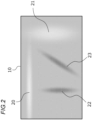
- Fig. 2 schematically shows an example of the streak-like region.
- the streak-like region has bright regions (20 and 21) having relatively high luminance with respect to the surrounding region and dark regions (22 and 23) having relatively low luminance with respect to the surrounding region.
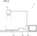
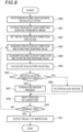
- FIG. 3 is a view showing the hardware configuration of the inspecting device 3.
- the inspecting device 3 quantitatively evaluates the occurrence degree of a streak-like region in the plane light source device 1 and automatically determines the presence/absence of a streak-like region which necessitates removal as a defective product.
- the inspecting device 3 substantially includes an information processing device (computer) 30, an imaging device 31, a stage 32, and a constant current power source 33.
- the information processing device 30 includes a general-purpose or dedicated computer which has a CPU (central processing unit) as a hardware processor, a memory as a main storage, a storage device for storing programs or data in a non-transitory manner (such as a hard disk and a flash memory), an input device (such as a mouse device, a keyboard, and a touch panel), a display device, an interface with the imaging device 31, and a network interface.
- a CPU central processing unit
- the imaging device 31 is a device which photographs the plane light source device 1 placed on the stage 32 and outputs a digital image.
- the imaging device 31 may be an optical system, an imaging element, or a digital camera which has an interface with the information processing device 30. Since the process is for the purpose of measuring the luminance of the plane light source device 1, the camera may be a monochrome camera if the plane light source device 1 is a monochromatic light source, and the camera is preferably a color camera if the plane light source device 1 is a multi-color light source device.
- the plane light source device 1 to be inspected is placed on the stage 32.
- the constant current power source 33 is a device which supplies the plane light source device 1 with electric power.
- the imaging device 31 and the stage 32 may be provided in a clean bench.
- the size (the length and width) of the light-emitting surface or the light emission luminance may be different among different models of the plane light source devices 1. Therefore, depending on the size of the light-emitting surface to be inspected, the distance between the stage 32 and the imaging device 31 or the zoom of the imaging device 31 is preferably adjusted, so that the relation between one pixel of an image obtained by the imaging device 31 and an actual size on the light emitting surface is calibrated.
- the average luminance of an image obtained by the imaging device 31 is preferably calibrated by adjusting the exposure time of the imaging device 31 depending on the light emitting luminance of the test object. These kinds of calibration may be carried out automatically by the information processing device 30 or manually by an operator.
- Fig. 4 is a block diagram illustrating functions related to streak-like region detecting processing by the inspecting device 3.
- the inspecting device 3 includes an image acquiring unit 40, a first filter operation unit 41, a second filter operation unit 42, a detecting unit 43, an output unit 44, and a storing unit 45.
- the image acquiring unit 40 represents the function of obtaining, from the imaging device 31, image data acquired by photographing the plane light source device 1 for inspection.
- the first and second filter operation units 41 and 42 represent the function of carrying out filtering operation.
- the detecting unit 43 represents the function of detecting a streak-like region using filter response values obtained by the first and second filter operation units 41 and 42.
- the output unit 44 represents the function of outputting image data and information such as a result of inspection to the display device.
- the storing unit 45 represents the function of storing the filters used for inspection processing, a determination threshold value, response values, and evaluation values.
- the function shown in Fig. 4 is basically implemented as the CPU of the information processing device 30 loads necessary programs from the storing device and executes the programs. Note however that some or all of the functions may be substituted by a circuit such as an ASIC and an FPGA. Some or all of these functions may be executed by another computer by using cloud computing or distributed computing techniques.
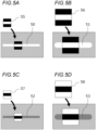
- Figs. 5A to 5D illustrate a conventional method
- Figs. 6A to 6D show the filters according to the embodiment.
- Fig. 5A is a schematic view of a kernel 55 for detecting a bright region 50 having a small width
- Fig. 5B is a schematic view of a kernel 56 for detecting a bright region 51 having a large width.
- the black region in the kernel represents a negative coefficient (such as "-1") while the white region represents a positive coefficient (such as "+1").
- Figs. 5C and 5D show kernels 57 and 58 corresponding to the widths of the dark regions 52 and 53, respectively.
- the kernels 57 and 58 for the dark regions have the coefficients with the sign inverted from that of the kernel 55 and 56 for the bright regions.
- two filters are combined to detect a streak-like region.
- a streak-like region extends in the X-direction of an image (rightwards in Fig. 6A ).
- two filters in other words, a first filter 61 responsive to increase in the luminance in the Y-direction (downwards in Fig. 6A ) and a second filter 62 responsive to decrease in the luminance in the Y-direction are used.
- the first filter 61 responds only to one edge of a streak-like region (which has luminance changing from low to high in the Y-direction), and the second filter 62 responds only to the other edge of the streak-like region (which has luminance changing from high to low in the Y-direction). Therefore, using an integrated value obtained by integrating a response value from the first filter 61 and a response value from the second filter 62 (such as the total value of two response values or the average of the values), a streak-like region having a width corresponding to the Y-distance (referred to as the "filter interval") between the two filters 61 and 62 can be detected.
- the filter interval a streak-like region having a width corresponding to the Y-distance
- the filter interval when a bright region 50 having a small width is to be detected, the filter interval may be small as shown in Fig. 6A , while when a bright region 51 having a large width is to be detected, and the filter interval may be large as shown in Fig. 6B . Furthermore, as shown in Figs. 6C and 6D , the positional relation between the first and second filters 61 and 62 may be reversed, so that dark regions 52 and 53 may be detected.
- multiple filters must be prepared corresponding to the widths of streak-like regions and on the basis of whether the region is a dark region or a bright region, while according to the embodiment, a bright region and a dark region with an arbitrary width may be detected using the two filters 61 and 62.
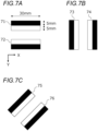
- Fig. 7A shows an exemplary filter for detecting a longitudinal streak and has a length of 30 mm (in the X-direction) and a width of 10 mm (in the Y-direction).
- the kernel size is 300 pix ⁇ 100 pix.
- a first filter 71 has a negative value (such as "-1") as the coefficient of the upper half and a positive value (such as "+1") as the coefficient of the lower half.
- a second filter 72 is the inverse of the first filter 71 in the vertical direction and has a positive value as the coefficient of the upper half and a negative value as the coefficient of the lower half. Note that the coefficients within the white and black regions do not have to be fixed values and may have a gradient.
- Fig. 7B shows examples of first and second filters 73 and 74 for detecting a lateral streak
- Fig. 7C shows examples of first and second filters 75 and 76 for detecting an oblique streak.
- an inspector provides the plane light source device 1 on the stage 32 in a prescribed position so that the light-emitting surface faces the side of the imaging device 31.
- the plane light source device 1 is connected to the constant current power source 33 to drive the light sources 11, and the plane light source device 1 is lit.
- the test object is provided manually in the inspecting device 3 according to the embodiment, while operation such as introduction, positioning, and connection with the power source, and withdrawal of the test object may be automated.
- step S80 the imaging device 31 photographs the plane light source device 1 in the lit state, and the image acquiring unit 40 takes in image data from the imaging device 31.
- the resolution of the image is arbitrary while according to the embodiment, the image has a resolution of about 0.1 mm (an actual size on the light-emitting surface) per pixel.
- step S81 the image acquiring unit 40 extracts only the region of the light-emitting surface from the input image taken in step S80.
- the image of the extracted region of the light-emitting surface will be referred to as a "light-emitting surface image.”
- Fig. 9A illustrates an example of an input image 90
- Fig. 9B illustrates an example of the light-emitting surface image 91 extracted from the input image 90.
- the light-emitting surface image 91 is generated so that the long sides of the light-emitting surface are parallel with the X-axis of the image.
- the reference numeral 92 indicates a longitudinal streak (a bright region).
- the light-emitting surface region may be extracted by any method.
- the image acquiring unit 40 may (1) binarize the original image, (2) remove noises in the background region (the region other than the light-emitting surface) by closing processing, and then (3) extract the contour of the light-emitting surface.
- inclination correction rotational correction
- step S83 the first filter operation unit 41 carries out scanning using the first filter 71 in the Y-direction and calculates a response value (referred to as a "first response value") by the first filter 71 in each of Y-positions.
- Fig. 10 shows the flow of step S83 in detail.
- the first response value is a result of sum-of-product arithmetic calculation of pixel values corresponding to the coefficient of the first filter 71. If the result of sum-of-product arithmetic operation is a negative value, the response value may be set to zero.
- the calculated first response value is stored in the storing unit 45 together with information on the application position (the X-position and the Y-position) of the first filter 71 (step S102). Thereafter, as the Y-position of the filter is shifted by one pixel (step S103), the processing from steps S101 to S102 is repeated until the filter reaches the terminal end of the inspection range in the Y-direction (step S104).
- the inspection range may be the entire light-emitting surface image 91 or a part of the light-emitting surface image 91 (if for example the area expected to have a longitudinal streak is previously known).
- step S84 the second filter operation unit 42 carries out scanning using the second filter 72 in the Y-direction and calculates a response value (referred to as a second response value) in each of Y-positions by the second filter 72.
- the processing in step S84 is identical to the processing in step S83 except that the different filter is used.
- the second response value calculated in step S84 is stored in the storing unit 45 together with information on the application position of the second filter 72.
- step S85 the detecting unit 43 calculates a maximum value R(x) for the integrated value of the first and second response values for example by the following expression.
- the value of R(x) is a value obtained by quantifying the occurrence degree of a streak-like region in an X-position x and will be hereinafter referred to as a "streak-like region evaluation value".
- R x max i , j ⁇ ⁇ ; i ⁇ j ⁇ m R 1 x i + R 2 x j
- Ri(x, i) is a first response value in the X-position x and a Y-position i
- R 2 (x, j) is a second response value in an X-position x and a Y-position j
- ⁇ is an inspection range in the Y-direction.
- m is the width of a white region (or a black region) in the kernels of the filters 71 and 72 in the Y-direction
- is the absolute value of the difference between i and j or the filter interval. The condition expressed by
- the above expression indicates that a combination of first and second response values which gives a maximum value R(x) for the integrated value is selected from multiple first response values Ri(x, i) and multiple second response values R 2 (x, j) which are obtained in the X-position x by shifting (scanning using) the two filters 71 and 72 in the Y-direction.
- both a bright region and a dark region can be detected because both cases in which the first filter 71 is positioned above as shown in Figs. 6A and 6B and the second filter 72 is positioned above as shown in Figs. 6C and 6D are taken into account. More specifically, if a combination of i and j which gives a streak-like region evaluation value R(x) satisfies i ⁇ j, the region is a bright region, and if the combination satisfies i>j, the region is a dark region. Note that in order to detect only a bright region, the restriction expressed by i ⁇ j may be added in the above expression, while in order to detect only a dark region, the restriction expressed by i>j may be added in the above expression.
- step S86 the detecting unit 43 compares the streak-like region evaluation value R(x) obtained in step S85 to a determination threshold value.
- the determination threshold value is used to determine the presence/absence of a streak-like region and may be predetermined depending on a result of sensory inspection or a result of experiments.
- the detecting unit 43 determines that "a streak-like region is in the position x" if the streak-like region evaluation value R(x) is greater than the determination threshold value (step S87) and otherwise determines that "no streak-like region exists in the position x" (step S88).
- the processing from steps S83 to S89 is repeated until the filter reaches the terminal end of the inspection range in the X-direction (step S90).
- the inspection range may be the entire light-emitting surface image 91 or a part of the light-emitting surface image 91 (if for example the area expected to have a longitudinal streak is previously known).
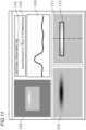
- the output unit 44 produces a screen image for outputting information obtained by the detecting unit 43 and outputs the screen image to the display device.
- Fig. 11 illustrates an example of the output screen image as a result of inspection.
- the output screen image includes an input image 110 taken from the imaging device 31, a light-emitting surface image 111 cut from the input image 110, and an image 112 (such as a pseudo color image) in which the light-emitting surface image 111 is processed to make luminance unevenness more noticeable.
- the light-emitting surface image 111 is superposed with information 113 indicating a position in which a streak-like region appears (for example a frame delineating an image region in which the streak-like region evaluation value R(x) exceeds the determination threshold value).
- the screen image also includes a maximum value max R(x) 114 for the streak-like region evaluation value, its determination result 115, and a luminance profile 116 in the Y-direction in the X-position in which the maximum max value max R(x) for the streak-like region evaluation value is obtained (the chain-dotted line in Fig. 11 ).
- an evaluation value representing the occurrence degree of a streak-like region is calculated on the basis of a photographed image of the light-emitting surface of the plane light source device 1, and the presence/absence of a streak-like region can be determined on the basis of the evaluation value. Therefore, objective and automatic inspection for streak-like regions may be performed. Since a streak-like region with an arbitrary width can be detected using only two filters, a lot of filters do not have to be prepared in advance unlike the conventional method. Therefore, the man-hours in designing the filters and the memory capacity for the filters can be considerably reduced.
- the method according to the present invention provides an advantageous effect in that the time for processing can be shorter than the conventional method when two or more kinds of streak-like regions are to be detected or the width of a streak-like region is indefinite.
- the light-emitting surface image 111 is superposed with information 113 which indicates the position of a streak-like region, which allows the inspector to grasp the position of interest with the streak-like region intuitively and more easily, which is also useful in checking the actual product. More specifically, the luminance profile 116 is also displayed, so that the state of the streak-like region (the difference in luminance with respect to the surrounding region) may be understood.
- the streak-like region evaluation value is obtained for each X-position of a filter
- a streak-like region evaluation value is obtained for each filter interval (i.e., for each width of a streak-like region).
- Figs. 12 and 13 are flowcharts for illustrating inspection processing for a longitudinal streak according to the second embodiment.
- scanning is carried out in the Y-direction and the X-direction through the processing in steps S80 to S84, S89, and S90, and first and second values in each of the X-positions and each of the Y-positions within the inspection range are calculated and stored in the storing unit 45.
- These kinds of processing are identical to the processing steps indicated by the same numbers in the flowchart in Fig. 8 according to the first embodiment.
- a streak-like region evaluation value for each width is calculated.
- a streak-like region evaluation value is obtained when the width w is 4 mm, 6 mm, 8 mm, and 10 mm by way of illustration.
- step S120 the detecting unit 43 sets an initial value of 4 mm for the width w.
- step S121 the detecting unit 43 sets an initial value of for example 5 mm for a Y-position y.
- the detecting unit 43 calculates a streak-like region evaluation value R(y, w) for example by the following expression.
- the value of R(y, w) is a value obtained by quantifying the occurrence degree of a streak-like region having a width w in the Y-position y.
- R y w ⁇ k ⁇ ⁇ R 1 k y + R 2 k , y + w
- R 1 (k, y) is a first response value in an X-position k and a Y-position y
- R 2 (k, y+w) is a second response value in an X-position k and a Y-position y+w.
- ⁇ is an inspection range in the X-direction.
- the above expression indicates that a value R(y, w) is calculated and the value is obtained by integrating multiple first response values R 1 (k, y) and multiple second response values R 2 (k, y+w) which are obtained by shifting (scanning using) the two filters 71 and 72 in the X-direction while the Y-positions of two filters 71 and 72 and the filter interval are kept constant.
- step S123 the detecting unit 43 compares the streak-like region evaluation value R (y, w) obtained in step S122 to a determination threshold value.
- the detecting unit 43 determines that "a streak-like region with a width w is in the position y" if the streak-like region evaluation value R(y, w) is greater than the determination threshold value (step S124) and otherwise determines that "no streak-like region with the width w exists in the position y" (step S125).
- steps S122 to S125 is repeated until the value of y reaches the terminal end of the inspection range in the Y-direction (S127) while y is shifted by one pixel (step S126). Then, as the width w is increased by 2 mm (step S128), the processing from steps S121 to S127 is repeated until the value w reaches 10 mm (step S129). In this way, the detection processing for the streak-like regions with widths w of 4 mm, 6 mm, 8 mm, and 10 mm ends. The processing thereafter is identical to that of the first embodiment.
- the streak-like region evaluation value R(y, w) is greater as a bright region or a dark region extending in the X-direction is longer. Therefore, a streak-like region (a longitudinal streak) extending in the X-direction can be detected accurately by evaluating the occurrence degree of a streak-like region using the evaluation value R(y, w).
- an evaluation value R(y, w) is obtained for each combination of a Y-position y and a width w.
- This method is advantageous in that all the longitudinal streaks appearing in an image can be detected. Meanwhile, if it is sufficient to detect/evaluate a longitudinal streak most intensely appearing in an image, an evaluation value R(w) or an evaluation value R as in the following expression may be used.
- the evaluation value R(w) is a value obtained by quantifying the occurrence degree of a streak-like region having a width w, and the evaluation value R is a value obtained by quantifying the occurrence degree of a streak-like region having an arbitrary width.
- the description of the embodiments is only for the purpose of illustrating the present invention.
- the invention is not limited by the above specific embodiments, and various modifications can be made within the scope of technical ideas of the invention.
- the plane light source device having a rectangular light-emitting surface is illustrated by way of example, while the shape of the light-emitting surface may be any other shape than the rectangular shape.
- the streak-like region evaluation value is only an example, and if the value is obtained by integrating the first response values by the first filter and the second response values by the second filter, the value may be designed in any other way.
- the detecting processing for a longitudinal streak-like region is illustrated, while it should be understood that the kernels and the scanning directions of the filters may be changed, as appropriate, so that a lateral streak or an oblique streak can be detected. Naturally, two or more kinds of streak-like regions among the longitudinal streak, the lateral streak, and the oblique streak may be detected.
Applications Claiming Priority (2)
| Application Number | Priority Date | Filing Date | Title |
|---|---|---|---|
| JP2016243249A JP6337949B1 (ja) | 2016-12-15 | 2016-12-15 | スジ状領域検出装置およびスジ状領域検出方法 |
| PCT/JP2017/038324 WO2018110089A1 (ja) | 2016-12-15 | 2017-10-24 | スジ状領域検出装置、スジ状領域検出方法、プログラム |
Publications (3)
| Publication Number | Publication Date |
|---|---|
| EP3557526A1 EP3557526A1 (en) | 2019-10-23 |
| EP3557526A4 EP3557526A4 (en) | 2020-06-10 |
| EP3557526B1 true EP3557526B1 (en) | 2024-02-14 |
Family
ID=62487559
Family Applications (1)
| Application Number | Title | Priority Date | Filing Date |
|---|---|---|---|
| EP17880750.9A Active EP3557526B1 (en) | 2016-12-15 | 2017-10-24 | Striated region detection device, striated region detection method, and program |
Country Status (7)
| Country | Link |
|---|---|
| US (1) | US10846869B2 (zh) |
| EP (1) | EP3557526B1 (zh) |
| JP (1) | JP6337949B1 (zh) |
| KR (1) | KR20190040067A (zh) |
| CN (1) | CN109791691B (zh) |
| TW (1) | TWI647660B (zh) |
| WO (1) | WO2018110089A1 (zh) |
Families Citing this family (1)
| Publication number | Priority date | Publication date | Assignee | Title |
|---|---|---|---|---|
| JP7004826B2 (ja) * | 2019-08-07 | 2022-01-21 | 株式会社日立ハイテク | 寸法計測装置、寸法計測方法及び半導体製造システム |
Family Cites Families (33)
| Publication number | Priority date | Publication date | Assignee | Title |
|---|---|---|---|---|
| GB1405409A (en) * | 1971-10-08 | 1975-09-10 | Emi Ltd | Colour television cameras |
| JP3254288B2 (ja) * | 1993-03-04 | 2002-02-04 | 大日本印刷株式会社 | スジ検査方法 |
| US6275600B1 (en) * | 1998-03-09 | 2001-08-14 | I.Data International, Inc. | Measuring image characteristics of output from a digital printer |
| JP3574584B2 (ja) * | 1998-12-16 | 2004-10-06 | 富士通株式会社 | 表画像処理装置及びそのプログラム記憶媒体 |
| US6393161B1 (en) * | 1999-04-26 | 2002-05-21 | Xerox Corporation | Software system for minimizing image defects in a hard-copy input scanner |
| TW424398B (en) * | 1999-06-10 | 2001-03-01 | Chen Yung Chang | Method and system of automatic spectral responsivity measurement for digital color cameras |
| US7043080B1 (en) * | 2000-11-21 | 2006-05-09 | Sharp Laboratories Of America, Inc. | Methods and systems for text detection in mixed-context documents using local geometric signatures |
| US7116841B2 (en) * | 2001-08-30 | 2006-10-03 | Micron Technology, Inc. | Apparatus, method, and product for downscaling an image |
| US7450746B2 (en) * | 2002-06-07 | 2008-11-11 | Verathon Inc. | System and method for cardiac imaging |
| JP4266798B2 (ja) * | 2003-12-15 | 2009-05-20 | キヤノン株式会社 | パターン検出装置及びパターン検出方法 |
| US7577297B2 (en) * | 2002-12-16 | 2009-08-18 | Canon Kabushiki Kaisha | Pattern identification method, device thereof, and program thereof |
| JP4298283B2 (ja) * | 2002-12-16 | 2009-07-15 | キヤノン株式会社 | パターン認識装置、パターン認識方法、及びプログラム |
| JP2004289496A (ja) * | 2003-03-20 | 2004-10-14 | Ricoh Co Ltd | 画像再生装置、画像再生方法およびこの方法をコンピュータに実行させるためのプログラム |
| US7424169B2 (en) * | 2003-08-15 | 2008-09-09 | Xerox Corporation | Active compensation of streaks using spatial filtering and feedback control |
| JP2005346300A (ja) * | 2004-06-01 | 2005-12-15 | Seiko Epson Corp | 筋状欠陥検出方法及び装置 |
| WO2006090449A1 (ja) * | 2005-02-23 | 2006-08-31 | Fujitsu Limited | 画像処理方法、画像処理装置、画像処理システム及びコンピュータプログラム |
| JP2007285753A (ja) * | 2006-04-13 | 2007-11-01 | Seiko Epson Corp | 欠陥検出方法および欠陥検出装置 |
| JP4692371B2 (ja) * | 2006-04-26 | 2011-06-01 | オムロン株式会社 | 画像処理装置、画像処理方法、画像処理プログラム、および画像処理プログラムを記録した記録媒体、ならびに移動物体検出システム |
| CN101448461B (zh) * | 2006-05-19 | 2011-04-06 | 株式会社日立医药 | 超声波诊断装置及边界提取方法 |
| JP5675253B2 (ja) * | 2009-12-28 | 2015-02-25 | キヤノン株式会社 | 画像処理装置、画像処理方法及びコンピュータプログラム |
| JP2011244085A (ja) * | 2010-05-14 | 2011-12-01 | Sony Corp | 信号処理装置及び信号処理方法 |
| JP2012038423A (ja) * | 2010-08-03 | 2012-02-23 | Mitsubishi Rayon Co Ltd | 導光体および面光源装置 |
| JP2012042720A (ja) * | 2010-08-19 | 2012-03-01 | Sony Corp | 画像処理装置および方法、並びにプログラム |
| JP2012058978A (ja) * | 2010-09-08 | 2012-03-22 | Canon Inc | 画像処理装置、画像処理方法及びプログラム |
| US9036937B2 (en) * | 2010-11-15 | 2015-05-19 | Qualcomm Incorporated | Fast repeated integral images |
| JP5644413B2 (ja) * | 2010-11-22 | 2014-12-24 | 三菱レイヨン株式会社 | 導光体、面光源装置及び画像表示装置 |
| JP2012129743A (ja) * | 2010-12-14 | 2012-07-05 | Nec Access Technica Ltd | 画像処理装置、画像処理方法および画像処理プログラム |
| US8761454B2 (en) * | 2011-05-10 | 2014-06-24 | Hewlett-Packard Development Company, L.P. | Detecting streaks in printed images |
| JP6122269B2 (ja) * | 2011-12-16 | 2017-04-26 | キヤノン株式会社 | 画像処理装置、画像処理方法、及びプログラム |
| JP2015082053A (ja) * | 2013-10-23 | 2015-04-27 | 富士ゼロックス株式会社 | 画像形成装置 |
| JP6307873B2 (ja) * | 2013-12-24 | 2018-04-11 | 富士通株式会社 | 対象線検出装置、方法、及びプログラム |
| JP6557943B2 (ja) * | 2014-01-15 | 2019-08-14 | オムロン株式会社 | 画像照合装置、画像センサ、処理システム、画像照合方法 |
| JP6700933B2 (ja) * | 2016-04-20 | 2020-05-27 | キヤノン株式会社 | 画像形成装置 |
-
2016
- 2016-12-15 JP JP2016243249A patent/JP6337949B1/ja active Active
-
2017
- 2017-10-24 EP EP17880750.9A patent/EP3557526B1/en active Active
- 2017-10-24 KR KR1020197008961A patent/KR20190040067A/ko not_active Application Discontinuation
- 2017-10-24 US US16/340,153 patent/US10846869B2/en active Active
- 2017-10-24 CN CN201780059575.2A patent/CN109791691B/zh active Active
- 2017-10-24 WO PCT/JP2017/038324 patent/WO2018110089A1/ja unknown
- 2017-10-26 TW TW106136810A patent/TWI647660B/zh active
Also Published As
| Publication number | Publication date |
|---|---|
| TW201824183A (zh) | 2018-07-01 |
| JP6337949B1 (ja) | 2018-06-06 |
| WO2018110089A1 (ja) | 2018-06-21 |
| KR20190040067A (ko) | 2019-04-16 |
| EP3557526A4 (en) | 2020-06-10 |
| JP2018097717A (ja) | 2018-06-21 |
| TWI647660B (zh) | 2019-01-11 |
| US10846869B2 (en) | 2020-11-24 |
| US20190244373A1 (en) | 2019-08-08 |
| CN109791691A (zh) | 2019-05-21 |
| CN109791691B (zh) | 2023-06-06 |
| EP3557526A1 (en) | 2019-10-23 |
Similar Documents
| Publication | Publication Date | Title |
|---|---|---|
| EP3557216B1 (en) | Inspecting device, inspecting method, and program | |
| US10585045B2 (en) | Inspecting device, inspecting method, and program | |
| US11317067B2 (en) | Method and system for inspecting display image | |
| WO2017202114A1 (zh) | 确定用于检测的光照强度的方法和装置、及光学检测方法和装置 | |
| Le et al. | Novel framework for optical film defect detection and classification | |
| US20210183037A1 (en) | Image processing device, image processing method, and image processing non-transitory computer readable medium | |
| EP3557526B1 (en) | Striated region detection device, striated region detection method, and program | |
| US10379064B2 (en) | Substrate inspection device and substrate manufacturing method | |
| JP2012237585A (ja) | 欠陥検査方法 | |
| TWI753424B (zh) | 外觀檢查管理系統、外觀檢查管理裝置、外觀檢查管理方法以及程式 | |
| JP2000019064A (ja) | フィルム評価方法およびフィルム評価装置 | |
| TWI776275B (zh) | 影像辨識裝置以及影像辨識方法 | |
| KR101349662B1 (ko) | 광학 필름의 결함 판별 방법 | |
| TW200848721A (en) | Offline fault inspection appliance for transparent plastic samples on the basis of a consumer flatbed scanner with a transparency unit | |
| JP6690316B2 (ja) | シート状の被検査体の欠陥検査装置、欠陥検査方法及び欠陥検査システム | |
| TW202232090A (zh) | 光學膜片之剝離檢測方法 | |
| JPH10206344A (ja) | 光学的むら検査装置および光学的むら検査方法 |
Legal Events
| Date | Code | Title | Description |
|---|---|---|---|
| STAA | Information on the status of an ep patent application or granted ep patent |
Free format text: STATUS: THE INTERNATIONAL PUBLICATION HAS BEEN MADE |
|
| PUAI | Public reference made under article 153(3) epc to a published international application that has entered the european phase |
Free format text: ORIGINAL CODE: 0009012 |
|
| STAA | Information on the status of an ep patent application or granted ep patent |
Free format text: STATUS: REQUEST FOR EXAMINATION WAS MADE |
|
| 17P | Request for examination filed |
Effective date: 20190408 |
|
| AK | Designated contracting states |
Kind code of ref document: A1 Designated state(s): AL AT BE BG CH CY CZ DE DK EE ES FI FR GB GR HR HU IE IS IT LI LT LU LV MC MK MT NL NO PL PT RO RS SE SI SK SM TR |
|
| AX | Request for extension of the european patent |
Extension state: BA ME |
|
| DAV | Request for validation of the european patent (deleted) | ||
| DAX | Request for extension of the european patent (deleted) | ||
| A4 | Supplementary search report drawn up and despatched |
Effective date: 20200512 |
|
| RIC1 | Information provided on ipc code assigned before grant |
Ipc: G06T 7/00 20170101AFI20200506BHEP Ipc: G01M 11/00 20060101ALI20200506BHEP Ipc: G06T 7/60 20170101ALI20200506BHEP Ipc: G06T 7/12 20170101ALI20200506BHEP |
|
| GRAP | Despatch of communication of intention to grant a patent |
Free format text: ORIGINAL CODE: EPIDOSNIGR1 |
|
| STAA | Information on the status of an ep patent application or granted ep patent |
Free format text: STATUS: GRANT OF PATENT IS INTENDED |
|
| INTG | Intention to grant announced |
Effective date: 20231123 |
|
| GRAS | Grant fee paid |
Free format text: ORIGINAL CODE: EPIDOSNIGR3 |
|
| GRAA | (expected) grant |
Free format text: ORIGINAL CODE: 0009210 |
|
| STAA | Information on the status of an ep patent application or granted ep patent |
Free format text: STATUS: THE PATENT HAS BEEN GRANTED |
|
| AK | Designated contracting states |
Kind code of ref document: B1 Designated state(s): AL AT BE BG CH CY CZ DE DK EE ES FI FR GB GR HR HU IE IS IT LI LT LU LV MC MK MT NL NO PL PT RO RS SE SI SK SM TR |
|
| REG | Reference to a national code |
Ref country code: GB Ref legal event code: FG4D |
|
| REG | Reference to a national code |
Ref country code: CH Ref legal event code: EP |
|
| REG | Reference to a national code |
Ref country code: DE Ref legal event code: R096 Ref document number: 602017079234 Country of ref document: DE |
|
| REG | Reference to a national code |
Ref country code: IE Ref legal event code: FG4D |